Abstract
In indirect inertial confinement fusion (ICF), the prediction of gas pressures and mass flow rates in the hohlraum is critical for fielding the hohlraum film and the support tent. To this end, it is desirable to understand the gas filling and evacuation process through the microcapillary fill tube and the support tent. In this work, a unified flow simulation of the filling and evacuation processes through the microcapillary fill tube and the support tent in an ICF hohlraum was conducted to study the gas pressure and mass flow rate in the hohlraum. The effects of the support tent size and the microcapillary fill tube size on the critical pressure variation and pressure difference across the hole on the support tent are examined. The results indicate that an increase in the diameter of the hole and the hole number leads to a smaller pressure difference across the hole on the support tent. If the diameter of the hole on the support tent is larger than 0.06 mm, the critical pressure variation rate is nearly independent of the diameter and the hole number. Increases in the diameter and decreases in the length of the microcapillary fill tube induce a larger critical pressure variation rate and pressure difference across the hole, which is conductive to fielding the hohlraum film.
1. Introduction
In inertial confinement fusion (ICF), a capsule filled with deuterium-tritium is imploded to ignition and burns under appropriate conditions, which bring clean and sustainable energy [1,2,3,4,5]. In particular, the indirect drive approach of ICF relies on the efficient conversion of laser power to X-rays that heat and symmetrically drive the capsule implosion embedded in a cylindrical hohlraum [6,7]. The cylindrical hohlraum is initially filled through microcapillary fill tubes with low-Z gas to control the implosion symmetry [8,9]. However, the low-Z gas in the hohlraum is easy to diffuse to the surrounding vacuum, and gas pressure variations can cause a displacement of the polymeric film and the capsule support tent in the hohlraum [10,11]. Therefore, it is necessary to precisely control the filling and evacuation processes in the hohlraum in ICF experiments to prevent large displacements of the polymeric film and the capsule support tent, or even a rupture of the polymeric film and the capsule support tent.
Some experimental and nondestructive methods, i.e., interferometry, mass spectrometry, and interferometry, have been applied in ICF experiments [12,13,14]. Steinman et al. [15] measured the gas fill half-life of ICF glass capsules, using three independent techniques, namely, weighing, interferometry and mass spectrometry. The measured half-lives by the three independent techniques agreed within approximately 10% of the average. Through a white-light interferometry approach, which can be as accurate as results using the destructive bubble method, the measurement of the fuel gas pressure of ICF targets with multiple-shells was carried out by Wang et al. [16]. They studied the gas retention capability of ICF targets using interferometry with long-time vertical scanning. To investigate the 3He permeability of the deuterium-tritium (DT)-filled, fused silica ICF shell, the off-gassing rate was recorded by an automated data collection system in a small stainless steel cell with a known volume [17]. However, the gas pressure characteristics of the hohlraum are less understood. Moreover, because the hohlraum capsule is divided by the support tent into two parts, nondestructive methods are not suitable for measuring the pressure of each part of the hohlraum with the capsule support tent. Therefore, it is urgent to theoretically investigate the filling and evacuation processes in an inertial confinement fusion hohlraum with a support tent.
While the low-Z gas is diffusing to the vacuum through the microcapillary fill tubes and the support tent, the low-Z gas flow lies in the continuum flow region, the slip flow region, the transition flow region, and the free-molecular flow region [18,19]. In particular, deviating from the macroscopic continuum, the gas flow in the transitional flow region and the free-molecular flow region manifests a rarefied effect [20,21]. The classical Navier–Stokes equation is not suitable to describe the gas flow in this condition. Bhandarkar et al. [13] developed a slip model for compressible gas flow through microcapillary fill tubes on National Ignition Facility targets. The model was also successfully used to predict pressure change profiles in the hohlraum and showed good agreement with their experimental observations. However, the gas flow through the support tent in an inertial confinement fusion hohlraum is still waiting to be investigated. In addition, the effect of the support tent on gas pressure characteristics has not been clarified yet.
Therefore, a unified flow simulation of the gas filling and evacuation processes through the microcapillary fill tube and the support tent in the hohlraum is conducted to predict the gas pressure in the hohlraum, with a particular focus on the effects of the hole on the support tent size and the microcapillary fill tube size on critical pressure variations and pressure differences across the hole on the support tent. The dynamic pressures inside the hohlraum (including the left and right halves of the hohlraum) and outside the hohlraum during the filling and evacuation process are analyzed and discussed. The current study contributes to a fuller understanding of dynamic gas flow behaviors through the microcapillary fill tube and the support tent of the ICF hohlraum.
2. Mathematical Model
In an effort to study the gas retention characteristics of the hohlraum, as shown in Figure 1, a theoretical model of the filling and evacuation processes through the microcapillary fill tube and the support tent in an ICF hohlraum was developed. In our model, a cylindrical hohlraum with a volume of 17.49 m3 (diameter dh = 2.2 mm, length Lh = 4.6 mm) comprised the support tent and hohlraum film. The hohlraum was divided into the left part and the right part by the support tent. There were several support holes with diameter ds and number Ns on the support tent. A microcapillary fill tube with diameter dx = 0.1 mm and length Lx = 500 mm was used to connect the hohlraum to an infinitely large gas filling chamber. The pressures of the left half of the hohlraum and the right half of the hohlraum were PL and PR, respectively. Meanwhile, the pressure outside the hohlraum was Po, which was also the pressure of the gas filling chamber. Since we mainly focus on the gas flow of the hohlraum, neglecting changes in the temperature, the temperatures inside and outside the hohlraum Ti and To were set to be 298.15 K throughout the filling and evacuation processes. The gas flow in the hohlraum, which was filled with He, was assumed to follow the ideal gas state equation. To investigate the safety of the hohlraum film, the pressure difference between the inside and outside of the hohlraum, which was also the pressure difference across the hohlraum film, was defined as ΔPio = PR − Po. The critical value of the pressure difference across the hohlraum film was set as ΔPc = 0.5 atm, for fielding the hohlraum film [1].
Figure 1.
Schematic of the inertial confinement fusion hohlraum with the microcapillary fill tube and the support tent.
2.1. Governing Equations
To simulate the filling and evacuation processes, accounting for rarefaction effects, which cannot adequately be described by continuum flow mechanics, a unified flow model accounting for the entire Knudsen regime was proposed by Beskok and Karniadak [22]. Based on the unified flow model, the gas mass flow rate through the microcapillary fill tube can be expressed as follows:
where b = −1, .
The Knudsen number for the hohlraum is given by the following:
The parameter α is given by the following:
where α1 = 4, β = 0.4, and α0 = 1.19, which are obtained from experimental results of the air flow through a metal capillary by Tison [23].
Differentiating the gas state equation PV = mRT, we obtained the following:
Since the hohlraum was divided into two parts by the support tent, during the filling process the low-Z gas first enters the left half of the hohlraum through the microcapillary fill tube, and then the right half of the hohlraum through the support tent. For the gas evacuation process, the gas flows in the opposite direction. Hence, the gas state equation of the left half of the hohlraum the right half of the hohlraum was modified as follows:
Equation (5),(6) were modified to ignore the influence of temperature.
where and represent the gas mass flow rate of the left half of the hohlraum and the right half of the hohlraum. When the gas flow goes into the hohlraum, and are positive and vice versa.
The and at the moment t is:
where is the current gas mass flow rate outside the hohlraum, and is the current gas mass flow rate of the hole on the support tent, which can be obtained according to the following empirical formula of the mass flow rate ratio at the hole of the support tent.
where Pr = PHigh/PLow is the pressure ratio between the high-pressure half of the hohlraum and low-pressure half of the hohlraum. γ1, γ2, γ3, γ4 are the parameters related to Pr as follows:
γ1 = 8.299Pr3 − 4.166Pr2 + 1.974 Pr + 0.4733,
γ2 = 29.63Pr3 − 8.61Pr2 + 3.415 Pr + 0.6413,
γ3 = 2.01Pr3 + 8.269Pr2 + 2.963 Pr + 5.2,
γ4 = 286.5Pr3 − 145.4Pr2 + 30 Pr +4.025.
is the mass flow rate at the hole on the support tent when the gas flow is towards the vacuum and at the free-molecular region.
where is the mean molecular velocity.
2.2. Boundary Conditions and Numerical Solution
For the filling process, the low-Z gas first enters the left half of the hohlraum through the microcapillary fill tube, and then the right half of the hohlraum through the support tent. The left half of the hohlraum, the right half of the hohlraum and outside the hohlraum all start with a pressure of 0 atm and end with a pressure of 15 atm. The pressure variation rate outside the hohlraum is Φ.
For the gas evacuation process, the low-Z gas first evacuates from the right half of the hohlraum to the left half of the hohlraum through the support tent, and then to the gas filling chamber through the microcapillary fill tube. The left half of the hohlraum, the right half of the hohlraum and outside the hohlraum all start with a pressure of 15 atm and end with a pressure of 0 atm. The pressure variation rate outside the hohlraum is Φ.
The gas state equation and the unified flow theory equation along with the boundary conditions described above were solved by utilizing the Newton iterative technique to obtain a numerical solution to the gas flow model in the hohlraum. The equations were solved by self-programming using MATLAB 2010. Firstly, the gas mass flow rate , , and at the current time step can be obtained by solving Equations (1), (9)–(11) with the pressure value in the hohlraum of the previous time step. Then, we can get the pressure value in the hohlraum PL and PR, and the pressure outside the hohlraum Po at the current time step with the gas state Equations (7) and (8). To obtain the pressure value of the next time step, the numerical solution should be done again.
2.3. Case Validation
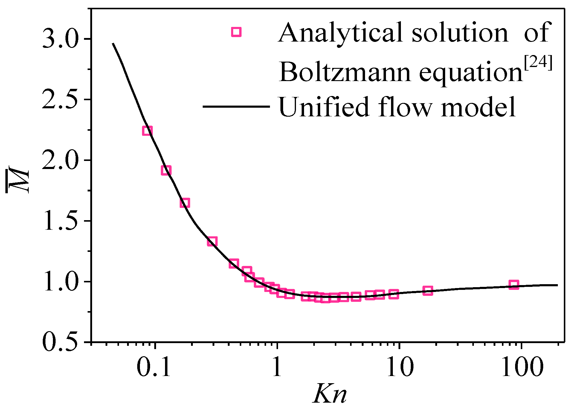
To verify the model, the dimensionless mass flow rates of the gas flow in an elongated channel are plotted with the Knudsen number as the abscissa in Figure 2.

Figure 2.
Comparison between the analytical solution of the Boltzmann equation [24] and numerical simulation based on the unified flow model. Reproduced with permission from S.K. Loyalka and S.A. Hamoodi, Physics of Fluids; published by AIP Publishing, 1990 [24].
The dimensionless gas mass flow rate is defined as follows:
Good agreement with a large Knudsen number range is observed between the mass flow rate prediction of the unified flow model and the analytic solutions of linearized Boltzmann solutions by Loyalka and Hamoodi [24], which confirms the validity of the unified flow model in the whole flow region in the hohlraum. In Reference [24], a cylindrical tube is considered with an enclosed gas flow driven by a pressure gradient parallel to the axis. The temperature of the tube is constant and the gas constant is 8.31/(mol·K).
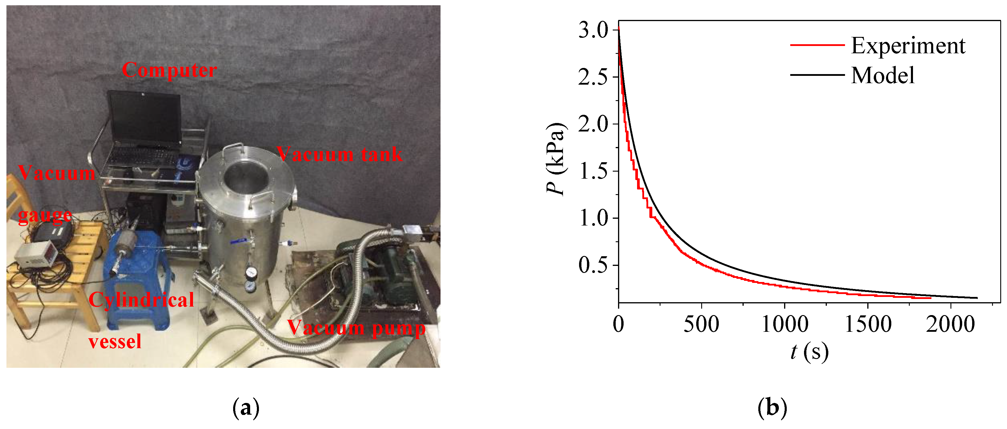
To validate the present model, the experimental setup for the gas evacuation process is shown in Figure 3a. A cylindrical vessel with the diameter of 9.4 cm and the height of the 10 cm was used to model the hohlraum. And the cylindrical vessel was connected to a vacuum tank, which was used to model the gas filling chamber. During the experiment, the air in the vacuum tank was removed by a vacuum pump, then the pressure in the cylindrical vessel dropped from 3000 Pa to 150 Pa which was measured by a vacuum gauge [25]. As shown in Figure 3b, the positive agreement of the air pressure evolution inside the cylindrical vessel between the numerical simulations and experimental data verified that the proposed model was able to predict the dynamic pressure in the hohlraum.
Figure 3.
Comparison of the gas evacuation process between the numerical simulations and experimental data: (a) experimental setup; (b) air pressure evolution.
3. Results and Discussions
3.1. Filling and Evacuation Processes
To elucidate the effect of the pressure variation rate on the gas flow in the hohlraum, this study investigated gas pressure characteristics during the gas evacuation and filling processes. In this section, the number of holes on the support tent is set to 1, and the diameter of the hole on the support tent is set to 0.2 mm. Figure 4 shows the filling of low-Z gas into the hohlraum. The gas mass flow rate quickly rose to the highest value once the filling process started. Simultaneously, the pressure difference across the hohlraum film ΔPio rose instantly to 0.324 atm (Φ = 10 atm/min) or 0.49 atm (Φ = 23 atm/min). Next, the gas mass flow rate rapidly decreased to a steady-state value and then the pressure difference across the hohlraum film gradually decreased. Furthermore, the pressure revolutions of the left half of the hohlraum and the right half of the hohlraum were basically synchronized. Additionally, the pressure difference across the hole on the support tent ΔPLR = PL − PR stabilized at a finite value for a long period after reaching a peak at the initial time. As the pressure variation rate rose, both the above two pressure differences increased. When the rate of increase in pressure was 23 atm/min, the pressure difference across the hohlraum film ΔPio was 0.49 atm, which was quite near the critical pressure difference ΔPc.
Figure 4.
Gas flow during the gas filling process: (a) Φ = 10 atm/min; (b) Φ = 23 atm/min.
Figure 5 shows the gas evacuation process. The gas evacuation mass flow rate first increased dramatically to a stable value, and maintained this for a long period of time. However, it decreased significantly in a short period of time at the end of the evacuation process. Correspondingly, the pressure of the left half of the hohlraum, the right half of the hohlraum, and outside the hohlraum gradually decreased as the time went on, but then decreased abruptly at the end of the gas evacuation process. However, the decrease of the gas pressure outside the hohlraum was larger than the pressure in the hohlraum. Therefore, the pressure difference across the hohlraum film ΔPio decreased as time increased. Meanwhile, the pressure difference across the hole on the support tent ΔPLR stabilized at a finite value for a long period before reaching a minimum at the end. As the pressure variation rate rose, both the above two pressure differences increased. When Φ = was 23 atm/min, the pressure difference across the hohlraum film ΔPio was 0.48 atm, which was quite near the critical pressure difference ΔPc.

Figure 5.
Gas flow during the gas evacuation process: (a) Φ = 10 atm/min; (b) Φ = 23 atm/min.
For fielding an ICF hohlraum film, it is essential to limit the pressure variation rate Φc to the critical pressure value ΔPc [26,27]. The effects of the pressure variation rate Φ on the maximum ΔPio and on the maximum ΔPLR during the filling and evacuation processes are shown in Figure 6. As shown in the figure, as the rate of pressure variation Φ increased, both ΔPio, max and ΔPLR, max increased. Additionally, the curves of ΔPio, max for the filling and evacuation process were very close to each other, and Φc for the filling and evacuation processes were both approximately equal to 24 atm/min. Under critical rates of the pressure variation Φc, the maximum pressure difference across the hole on the support tent ΔPLR, max was 6 × 10⁻⁵ atm. For the hohlraum in this study, the filling or evacuation pressure variation should have been less than 24 atm/min to prevent the rupture of the hohlraum film.
Figure 6.
Effects of the pressure variation rate during the filling and evacuation processes on the maximum ΔPio and ΔPLR.
3.2. Effect of the Hole on the Support Tent
The pressure difference across the hole on the support tent determines the displacement of the support tent, which also needs to be addressed for ICF. Figure 7 shows the time evolution of the pressure difference across the hohlraum film and between the left half of the hohlraum and the right half of the hohlraum with different diameters of the hole in the support tent. An increase in the diameter of the hole on the support tent led to a decrease in the pressure difference across the hohlraum film at the beginning of the gas evacuation process and at the end of the filling process. However, the maximum ΔPio was nearly independent of the diameter of the hole on the support tent. This result indicates that there was nearly no effect of the diameter of the hole in the support tent on ruptures of the hohlraum film. In addition, as the diameter of the hole on the support tent increased, the pressure difference across the hole on the support tent decreased, resulting in a larger displacement of the support tent.
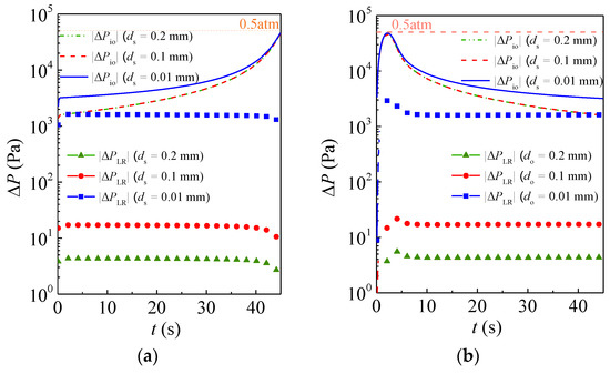
Figure 7.
Time evolution of the pressure difference between the inside and outside hohlraum and between the left half hohlraum and the right half hohlraum (Ns = 1). (a) Gas evacuation (Φ = 20 atm/min); (b) gas filling (Φ = 20 atm/min).
Figure 8 shows the effect of the diameter of the hole do of the support tent on the critical pressure variation rate Φc and the maximum pressure difference across the hole of the support tent ΔPLR, max. As seen from the figure, if the diameter of the hole on the support tent was smaller than 0.06 mm, increasing the diameter of the hole in the support tent increased the critical pressure variation rate Φc. If the diameter of the hole in the support tent wass larger than 0.06 mm, the critical pressure variation rate Φc was nearly independent of the diameter of the hole in the support tent, and the values for the filling and evacuation processes were very close, which was attributed to the small resistance of the support rent. In addition, the increasing area of the hole on the support tent made it easier for the low-Z gas to pass through the hole in the support tent, so the maximum pressure difference across the hole on the support tent ΔPLR, max decreased.
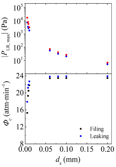
Figure 8.
Effect of the diameter of the hole on the support tent do on the critical pressure variation rate Φc and the maximum pressure difference across the hole on the support tent ΔPLR, max (Ns = 1).
The number of holes in the support tent is a variable for the ICF experiments. Figure 9 shows the effect of the number of holes in the support tent Ns on the critical pressure variation rate Φc and the maximum pressure difference across the holes in the support tent ΔPLR, max. When the diameter of the hole of the support tent was 50 μm, the critical pressure variation rate Φc during the filling process was close to that during the gas evacuation process. In addition, with more holes in the support tent, the critical pressure variation rate Φc increased gradually to a stable value, which was beneficial to the safety of the hohlraum film. When the diameter of the hole in the support tent was 0.2 mm, Φc remained constant both during the filling and evacuation processes. Furthermore, with more holes in the support tent, the gas could pass more easily through the support tent which increased the gas flow area. Consequently, the maximum pressure difference across the hole in the support tent ΔPLR, max decreased. Therefore, if the diameter of the hole on the support tent was larger than 0.06 mm, the critical pressure variation rate was nearly independent of the hole diameter and number.
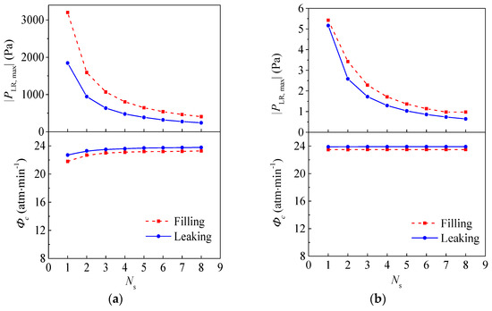
Figure 9.
Effect of the number of the hole on the support tent No on the critical pressure variation rate Φc and the maximum pressure difference across the hole on the support tent ΔPLR, max. (a) ds = 50 μm; (b) ds = 0.2 mm.
3.3. Effect of the Microcapillary Fill Tube
Apart from the support tent, the gas flow in the hohlraum was also affected by the microcapillary fill tube. Figure 10 shows the effect of the diameter of the microcapillary fill tube dx on the critical pressure variation rate Φc and the maximum pressure difference across the hole in the support tent ΔPLR, max. As the diameter of the microcapillary fill tube increased, both the critical pressure variation rate Φc and the maximum pressure difference across the hole in the support tent ΔPLR, max increased accordingly. Additionally, the curves of the critical pressure variation rate Φc for the filling and evacuation processes were very close to each other. Therefore, increasing the diameter of the microcapillary fill tube dx prevented failures of hohlraum films.
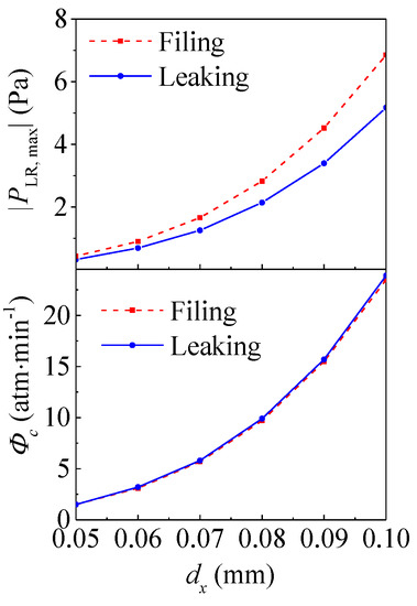
Figure 10.
Effect of the diameter of the microcapillary fill tube dx on the critical pressure variation rate Φc and the maximum pressure difference across the hole on the support tent ΔPLR, max. (do = 0.2 mm, Ns = 1, lx = 500 mm).
Figure 11 shows the effect of the length of the microcapillary fill tube lx on the critical pressure variation rate Φc and the maximum pressure difference across the hole of the support tent ΔPLR, max. As the length of the microcapillary fill tube increased, both the critical pressure variation rate Φc and the maximum pressure difference across the hole of the support tent ΔPLR, max decreased accordingly. Additionally, the curves of the critical pressure variation rate Φc for the filling and evacuation processes were very close to each other. Therefore, the diameter of the microcapillary fill tube lx should be reduced to improve the security of the hohlraum film [26,28]. Hence, an increase in the diameter of the microcapillary fill tube and a decrease in its length both is conductive to the fielding of the hohlraum film but may leads to the dangerous displacement of the target.
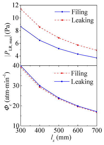
Figure 11.
Effects of the diameter of the microcapillary fill tube lx on the critical pressure variation rate Φc and the maximum pressure difference across the hole on the support tent ΔPLR, max. (do = 0.2 mm, Ns = 1, dx = 0.1 mm).
3.4. Effect of the Hohlraum Size
Apart from the structure parameters of the microcapillary fill tube and the support tent, one more significant issue which needs to be addressed regarding gas flow behaviors during the filling and evacuation processes is the size of the hohlraum [6]. Figure 12 shows a prediction of the critical pressure variation rate Φc and the maximum pressure difference across the hole of the support tent. By plotting the hohlraum volume V as the abscissa, we found that when the hohlraum volume V increased, and the critical pressure variation rate Φc decreased sharply, which is conducive to the high sensitivity of the hohlraum film to the pressure variation rate. Hence, it is essential to reduce the hohlraum size for the safety of the hohlraum. However, the maximum pressure difference across the hole of the support tent is independent of the hohlraum volume.
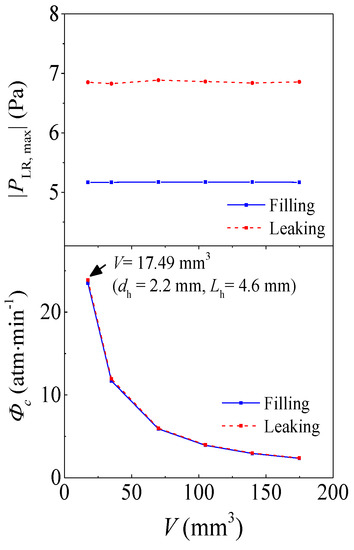
Figure 12.
Effect of the hohlraum volume on the critical pressure variation rate Φc and the maximum pressure difference across the hole on the support tent ΔPLR, max. (do = 0.2 mm, Ns = 1, dx = 0.1 mm, lx = 500 mm).
4. Conclusions
In this work, a unified flow simulation of the gas filling and evacuation processes through the microcapillary fill tube and the support tent in an ICF hohlraum was conducted to study the gas pressure and mass flow rate in the hohlraum. The effects of the hole size and the microcapillary fill tube size on the critical pressure variation and pressure difference across the hole on the support tent were examined and analyzed. Guidelines for safely filling and evacuating the ICF hohlraum were provided. The following conclusions can be drawn from the present results:
- An excessive filling or evacuation pressure variation rate leads to a large pressure difference across the hohlraum film and across the hole on the support tent, which may lead to a failure of the hohlraum. For the hohlraum in this study, the filling or evacuation pressure variation should be less than 24 atm/min to prevent the rupture of the hohlraum film.
- A support tent with a larger diameter and more holes is recommended. If the diameter of the hole on the support tent is larger than 0.06 mm, the critical pressure variation rate is nearly independent of the hole diameter and number.
- An increase in the diameter of the microcapillary fill tube and a decrease in its length both lead to a larger critical pressure variation rate and pressure difference across the hole on the support tent, which is conductive to the fielding of the hohlraum film but may leads to the dangerous displacement of the target.
- A small-size hohlraum is sensitive to the pressure variation rate of the hohlraum. However, the maximum pressure difference across the hole on the support tent is independent of the hohlraum volume.
For the multiscale gas flow during the filling and evacuation processes of the ICF hohlraum, this investigation not only contributes to a fuller understanding of dynamic gas flow behaviors through the microcapillary fill tube and the support tent of the ICF hohlraum, but also contributes to precisely controlling the gas mass flow rate and pressure variation rate via the optimized structure of the hohlraum, support tent, and microcapillary fill tube, which is of significant importance for the design of the indirect ICF system [29,30]. Since the gas flow in an ICF hohlraum is a complex multiscale flow problem, the future research work could focus on the hydrodynamics of gas filling and retention via the multiscale three-dimensional unsteady numerical simulation.
Author Contributions
Investigation, L.W. and H.Z.; Supervision, C.Y. and F.Y.
Funding
This research was funded by the National Natural Science Foundation of China (No.51706194).
Conflicts of Interest
The authors declare no conflict of interest.
Nomenclature
| Name | Definition |
| Knudsen number | |
| Symbols’ used Abbreviations | Symbol |
| b | Parameter for the mass flow rate |
| d | Diameter, mm |
| L | Length, mm |
| m | Mass, kg |
| Gas mass flow rate, kg/s | |
| Mass flow rate at the hole on the support tent when the gas flow is towards the vacuum and at the free-molecular region, kg/s | |
| Dimensionless gas mass flow rate | |
| Ns | Number of support holes |
| P | Pressure, atm or Pa |
| ΔP | Pressure difference, atm |
| Gas constant of He, J/(mol*K) | |
| , K | |
| t | Time, s |
| W | Mass flow rate ratio at the hole of the support tent |
| Mean molecular velocity, m/s | |
| V | Volume of hohlraum, mm3 |
| Subscrips | |
| avg | Average value |
| c | Critical value |
| h | Hohlraum |
| High-pressure half of the hohlraum | |
| i | Inside the hohlraum |
| io | Between inside and ouside the hohraum |
| L | Left half of the hohlraum |
| LR | Between the left half and the right half of the hohraum |
| Low | Low-pressure half of the hohlraum |
| max | Maximum value |
| o | Outside the hohlraum |
| Orifice | Through the support tent |
| R | Right half of the hohlraum |
| r | Ratio |
| s | Support hole |
| t | Current time step |
| x | Microcapillary fill tube |
| Greek symbols | |
| α | Parameter for the mass flow rate |
| α0 | Parameter obtained from experimental results of the air flow through a metal capillary |
| α1 | Parameter obtained from experimental results of the air flow through a metal capillary |
| β | Parameter obtained from experimental results of the air flow through a metal capillary |
| γ1 | Parameters related to the pressure ratio |
| γ2 | Parameters related to the pressure ratio |
| γ3 | Parameters related to the pressure ratio |
| γ4 | Parameters related to the pressure ratio |
| dynamic viscosity, N·s/m2 | |
| Pi | |
| Φ | Pressure variation rate, atm/min |
References
- Lindl, J.D.; Amendt, P.; Berger, R.L.; Glendinning, S.G.; Glenzer, S.H.; Haan, S.W.; Kauffman, R.L.; Landen, O.L.; Suter, L.J. The physics basis for ignition using indirect-drive targets on the national ignition facility. Phys. Plasmas 2004, 11, 339–491. [Google Scholar] [CrossRef]
- Zhang, C.B.; Gao, W.; Zhao, Y.J.; Chen, Y.P. Microfluidic generation of self-contained multicomponent microcapsules for self-healing materials. Appl. Phys. Lett. 2018, 113, 203702. [Google Scholar] [CrossRef]
- Lan, K.; Liu, J.; Li, Z.; Xie, X.; Huo, W.; Chen, Y.; Ren, G.; Zheng, C.; Yang, D.; Li, S.; et al. Progress in octahedral spherical hohlraum study. Matter Radiat. Extrem. 2016, 1, 8–27. [Google Scholar] [CrossRef]
- Chen, Y.; Gao, W.; Zhang, C.; Zhao, Y. Three-dimensional splitting microfluidics. Lab Chip 2016, 16, 1332–1339. [Google Scholar] [CrossRef]
- Deng, Z.; Liu, X.; Zhang, C.; Huang, Y.; Chen, Y. Melting behaviors of pcm in porous metal foam characterized by fractal geometry. Int. J. Heat Mass Transf. 2017, 113, 1031–1042. [Google Scholar] [CrossRef]
- Fernández, J.C.; Goldman, S.R.; Kline, J.L.; Dodd, E.S.; Gautier, C.; Grim, G.P.; Hegelich, B.M.; Montgomery, D.S.; Lanier, N.E.; Rose, H.; et al. Gas-filled hohlraum experiments at the national ignition facility. Phys. Plasmas 2006, 13, 056319. [Google Scholar] [CrossRef]
- Liu, M.; Su, L.; Li, J.; Chen, S.; Liu, Y.; Li, J.; Li, B.; Chen, Y.; Zhang, Z. Investigation of spherical and concentric mechanism of compound droplets. Matter Radiat. Extrem. 2016, 1, 213–223. [Google Scholar] [CrossRef]
- Meezan, N.; Edwards, M.; Hurricane, O.; Patel, P.; Callahan, D.; Hsing, W.; Town, R.; Albert, F.; Amendt, P.; Hopkins, L.B. Indirect drive ignition at the national ignition facility. Plasma Phys. Control. Fusion 2016, 59, 014021. [Google Scholar] [CrossRef]
- Kyrala, G.A.; Dixit, S.; Glenzer, S.; Kalantar, D.; Bradley, D.; Izumi, N.; Meezan, N.; Landen, O.L.; Callahan, D.; Weber, S.V.; et al. Measuring symmetry of implosions in cryogenic hohlraums at the nif using gated x-ray detectors (invited). Rev. Sci. Instrum. 2010, 81, 10E316. [Google Scholar] [CrossRef]
- Cook, R.; Kozioziemski, B.; Nikroo, A.; Wilkens, H.; Bhandarkar, S.; Forsman, A.; Haan, S.; Hoppe, M.; Huang, H.; Mapoles, E. National ignition facility target design and fabrication. Laser Part Beams 2008, 26, 479–487. [Google Scholar] [CrossRef]
- Smalyuk, V.A.; Robey, H.F.; Alday, C.L.; Amendt, P.; Aracne-Ruddle, C.; Bigelow, J.R.; Bunn, T.; Casey, D.T.; Chen, K.-C.; Clark, D.S.; et al. Review of hydro-instability experiments with alternate capsule supports in indirect-drive implosions on the national ignition facility. Phys. Plasmas 2018, 25, 072705. [Google Scholar] [CrossRef]
- Tierney, T.E.; Cobble, J.A.; DeVolder, B.G.; Hoffman, N.M.; Tubbs, D.L.; Bradley, P.A.; Goldman, S.R.; Magelssen, G.R.; Paisley, D.L. Gold Wall Ablation and Hohlraum Filling Measurements of Vacuum and Gas-Filled Hohlraums; High-Power Laser Ablation VI; International Society for Optics and Photonics: Taos, NM, USA, 2006; p. 626106. [Google Scholar]
- Bhandarkar, S.; Parham, T.; Fair, J. Modeling and experiments of compressible gas flow through microcapillary fill tubes on nif targets. Fusion Sci. Technol. 2011, 59, 51–57. [Google Scholar] [CrossRef]
- Froula, D.H.; Divol, L.; London, R.A.; Berger, R.L.; Döppner, T.; Meezan, N.B.; Ross, J.S.; Suter, L.J.; Sorce, C.; Glenzer, S.H. Observation of the density threshold behavior for the onset of stimulated raman scattering in high-temperature hohlraum plasmas. Phys. Rev. Lett. 2009, 103, 045006. [Google Scholar] [CrossRef] [PubMed]
- Steinman, D.A.; Alfonso, E.L.; Hoppe, M.L. Developments in capsule gas fill half-life determination. Fusion Sci. Technol. 2007, 51, 544–546. [Google Scholar] [CrossRef]
- Wang, Z.; Gao, D.; Ma, X.; Meng, J. White-light interferometry for measuring fuel pressure in icf polymer-microsphere targets. Fusion Sci. Technol. 2014, 66, 432–437. [Google Scholar] [CrossRef]
- Wermer, J.R.; Murdock, H.M.; Nobile, A.; Herrmann, H.W.; Venhaus, T.J.; Paglieri, S.N.; Langenbrunner, J.R.; Mack, J.M. Measurement of the 3he permeability of dt-filled fused silica inertial confinement fusion (icf) targets to study the effects of 3he on neutron emission during implosion. Fusion Sci. Technol. 2008, 54, 569–575. [Google Scholar] [CrossRef]
- Zhang, C.B.; Deng, Z.L.; Chen, Y.P. Temperature jump at rough gas-solid interface in couette flow with a rough surface described by cantor fractal. Int. J. Heat Mass Transf. 2014, 70, 322–329. [Google Scholar] [CrossRef]
- Yu, C.; Wu, S.; Yang, W. Theoretical investigation of gas filling and leaking in inertial confinement fusion hohlraum. Sustainability 2018, 10, 3763. [Google Scholar] [CrossRef]
- Sun, D.; Zhu, M.; Wang, J.; Sun, B. Lattice boltzmann modeling of bubble formation and dendritic growth in solidification of binary alloys. Int. J. Heat Mass Transf. 2016, 94, 474–487. [Google Scholar] [CrossRef]
- Zhang, C.; Yu, F.; Li, X.; Chen, Y. Gravity-capillary evaporation regimes in microgrooves. AICHE J. 2019, 65, 1119–1125. [Google Scholar] [CrossRef]
- Karniadakis, G.E.; Beskok, A.; Aluru, N. Microflows and Nanoflows: Fundamentals and Simulation; Springer-Verlag: New York, NY, USA, 2005; Volume 29. [Google Scholar]
- Tison, S.A. Experimental data and theoretical modeling of gas flows through metal capillary leaks. Vacuum 1993, 44, 1171–1175. [Google Scholar] [CrossRef]
- Loyalka, S.K.; Hamoodi, S.A. Poiseuille flow of a rarefied gas in a cylindrical tube: Solution of linearized boltzmann equation. Phys. Fluids A 1990, 2, 2061–2065. [Google Scholar] [CrossRef]
- Zhang, C.; Shen, C.; Chen, Y. Experimental study on flow condensation of mixture in a hydrophobic microchannel. Int. J. Heat Mass Transf. 2017, 104, 1135–1144. [Google Scholar] [CrossRef]
- Kucheyev, S.O.; Hamza, A.V. Condensed hydrogen for thermonuclear fusion. J. Appl. Phys. 2010, 108, 091101. [Google Scholar] [CrossRef]
- Solomon, D.E.; Henderson, T.M. Laser fusion targets. J. Phys. D Appl. Phys. 1975, 8, L85. [Google Scholar] [CrossRef]
- Zhang, Z.W.; Huang, Y.; Qi, X.B.; Liu, Y.Y.; Ma, X.J.; Li, B.; Huang, Y.H.; Zhang, L. Fabrication and half-life time of gas-fil led plastic hohlraum. High Power Laser Part. Beams 2011, 23, 133–136. [Google Scholar] [CrossRef]
- Kauffman, R.L.; Powers, L.V.; Dixit, S.N.; Glendinning, S.G.; Glenzer, S.H.; Kirkwood, R.K.; Landen, O.L.; MacGowan, B.J.; Moody, J.D.; Orzechowski, T.J.; et al. Improved gas-filled hohlraum performance on nova with beam smoothing. Phys. Plasmas 1998, 5, 1927–1934. [Google Scholar] [CrossRef]
- Vu, H.X.; Wallace, J.M.; Bezzerides, B. An analytical and numerical investigation of ion acoustic waves in a two-ion plasma. Phys. Plasmas 1994, 1, 3542–3556. [Google Scholar] [CrossRef]


© 2019 by the authors. Licensee MDPI, Basel, Switzerland. This article is an open access article distributed under the terms and conditions of the Creative Commons Attribution (CC BY) license (http://creativecommons.org/licenses/by/4.0/).