1. Introduction
Conventional hydraulic actuators have commonly been used in plenty of heavy equipment applications. Examples include the use of excavators and dozers in the construction industry, offshore drilling and marine machinery in the marine industry, active suspension systems in the automotive industry, and wearable robots in the medical device industry [
1,
2,
3]. According to one survey that addressed longer lifespans, the dependency of wearable robots using linear actuators should be increased, given the related increase in human life expectancy [
4]. Therefore, it is important for more studies to focus on increasing muscular strength using actuators, such as with wearable robots for rehabilitation training, in military applications, and in commercial applications. For hydraulic actuators, there are generally two ways to control a system: with a controlled pump or with a controlled valve. Controlled pumps have slow responses because the contained volumes are large, and the pressure must be built up initially. However, the pressure levels of both the lines and the flow are closely matched to the load requirements, resulting in much higher energy efficiency [
5]. On the other hand, controlled valves offer rapid responses because the contained volumes are small. Nonetheless, regardless of the load pressure, the energy efficiency is low because the supply pressure is constant, and internal leakages occur when changing the direction of the fluid in the valve [
6,
7]. Despite these disadvantages, the conventional hydraulic system is widely used in heavy industries due to its high power and torque ratios, rapid responses, and excellent heat resistance [
8]. However, mainly due to the low energy efficiency, fluid leakages from valves, large volume size, and limited installation space, the application of wearable robots is limited. Additionally, because hydraulic fluid is the main energy medium in the system, the system contains uncertain fluid parameters in hydraulic control. On the other hand, electric linear actuators have distinct advantages over hydraulic actuators in terms of their simplicity and their highly efficient energy usage, but their poor load holding capabilities continue to be a problem. For example, electric linear actuators constantly consume energy to maintain the current positional holding of a heavy weight. As a result, the energy efficiency is reduced. Wearable robots are also associated with related safety issues. For instance, the driving force of electric linear actuators is controlled by the torque force of a motor. However, if the power of the motor fails, a wearable robot may be damaged due to its heavy weight. In addition, they are not as cost-effective as hydraulic actuators in terms of their power and torque ratios [
9]. Therefore, the development of a much more flexible system that is applicable to multiple areas is required to meet the rapidly changing demands of current technologies.
The development of an electro-hydraulic actuator (EHA) utilizing a hydraulic system with electrical power is one solution that may overcome these drawbacks [
10]. EHAs can be operated with either pump-controlled or valve-controlled approaches, and they are considered to be more flexible systems. The pump-controlled EHA allows direct position adjustments, and when reaching the target value, the constant supply pressure is stopped. As a result, the pump-controlled EHA has higher energy efficiency than the conventional hydraulic actuator and the valve-controlled type of EHA [
5,
9]. However, most EHA studies conducted thus far have focused on valve-controlled EHAs [
11,
12,
13,
14,
15,
16,
17,
18]; these types offer a quick response, but their energy efficiency is low due to the supply of constant pressure [
5]. Due to this constant pressure supply, leakage from the valves increases gradually. This accumulated leakage leads to poor performance due to the introduction of many uncertainties. In addition, the dynamic system changes due to the presence of a single rod cylinder, and uncertain fluid parameters occur in hydraulic control. As a result, these model uncertainties lead to nonlinear systems.
Several approaches have been proposed to resolve the nonlinearity issue associated with valve-controlled EHAs, and many studies have utilized simulations and experiments. For example, Yong Yang, Lei Yong Yang, Lei Ma, and Deqing Huang solved this issue by using valve-controlled EHAs with an exoskeleton that handles loads with the lower limbs based on a backstepping tracking method with feedback learning [
11]. Although their controller was verified in a simulation, it is necessary to verify it with actual experiments. In addition, backstepping control, adaptive robust control, adaptive sliding mode control, and pressure feedback have been utilized in experimental efforts to address the nonlinearity issue of valve-controlled EHAs. However, with the valve-controlled method, the double-rod cylinder and single-rod cylinder used are dynamically different and applying the load to the robot leg with the single-rod cylinder was found to be challenging [
12,
13,
14,
15,
16]. Although non-linear control methods have been demonstrated with valve-controlled EHAs, these systems remain associated with low energy efficiency levels due to leakage problems stemming from the valve characteristics [
5,
6,
7]. Mostly, given its effectiveness for relatively high-order systems, backstepping or sliding mode control schemes have been utilized to solve these nonlinear uncertain systems. Thus far, studies have focused on adaptive backstepping control, tuning a PID sliding mode controller and a sensor fault-tolerance control design using a pump-controlled EHA [
19,
20,
21]. With the application of increasingly intelligent systems, energy efficiency becomes more important. Therefore, more advanced studies to improve energy efficiency levels when using pump-controlled EHAs are necessary.
In relation to EHA development, considering a wearable robot, dynamics and safety issues are crucial. In work on system safety, a sensor-fault-tolerant control design for a pump-controlled EHA has been used to maintain system performance [
21]. However, fault tolerance control is a software performance, and not a hardware performance issue. Hence, the control will not function properly if the motor completely malfunctions or is turned off. Therefore, this paper presents a means of position control for a pump-controlled electro-hydraulic actuator (EHA) system with an adaptive sliding mode control scheme and locking circuit design. The proposed circuit design maintains the pressure in the actuator, regardless of an external environment. In other words, even if the motor is stationary or fails, the system is stopped while maintaining the internal pressure in the actuator, thereby preventing damage to the robot and increasing the safety and energy efficiency. The proposed ASMC is used as an error compensation method, with certain nonlinearities related to uncertain fluid parameters and unknown model parameters in a hydraulic control scheme.
In this paper, the design and performance of a pump-controlled EHA are presented considering its use in a wearable robot. The proposed design of the pump-controlled EHA is described, and the EHA performance is verified with Simscape Fluids in
Section 2. A controller based on adaptive sliding mode control is presented, and the stability of the system is proved with the Lyapunov theorem in
Section 3. The proposed adaptive control scheme is demonstrated by experiments in
Section 4. Finally, the conclusions of this paper are presented in the last section.
2. Mathematical Modeling of an Electro-Hydraulic Actuator
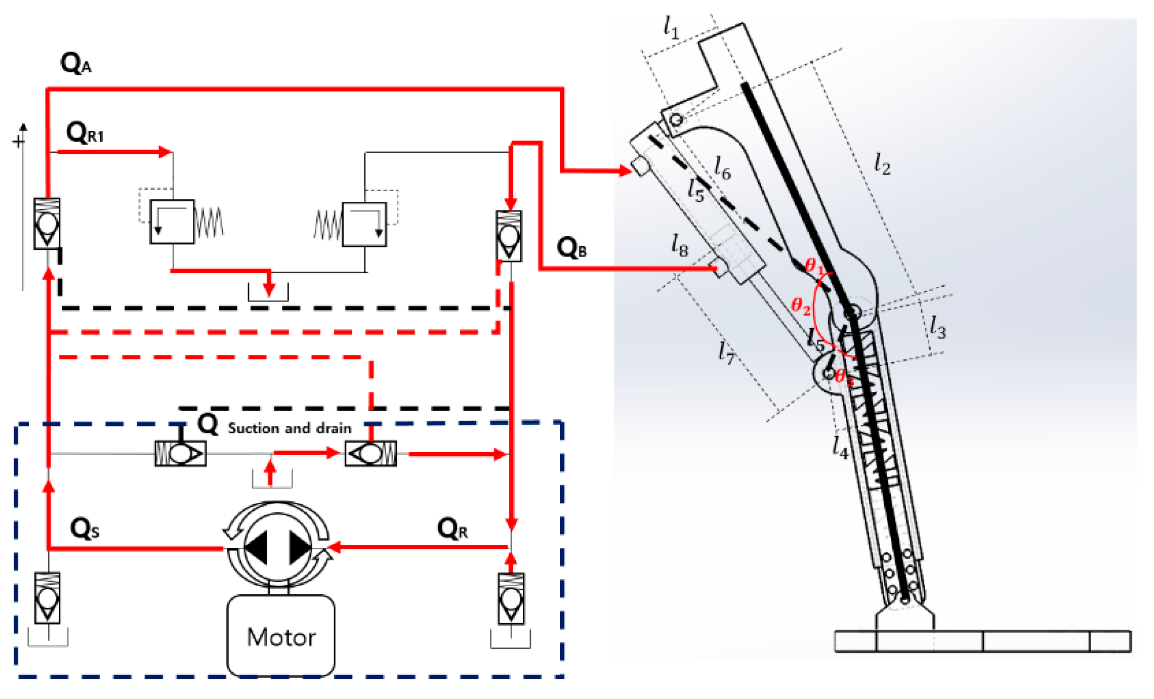
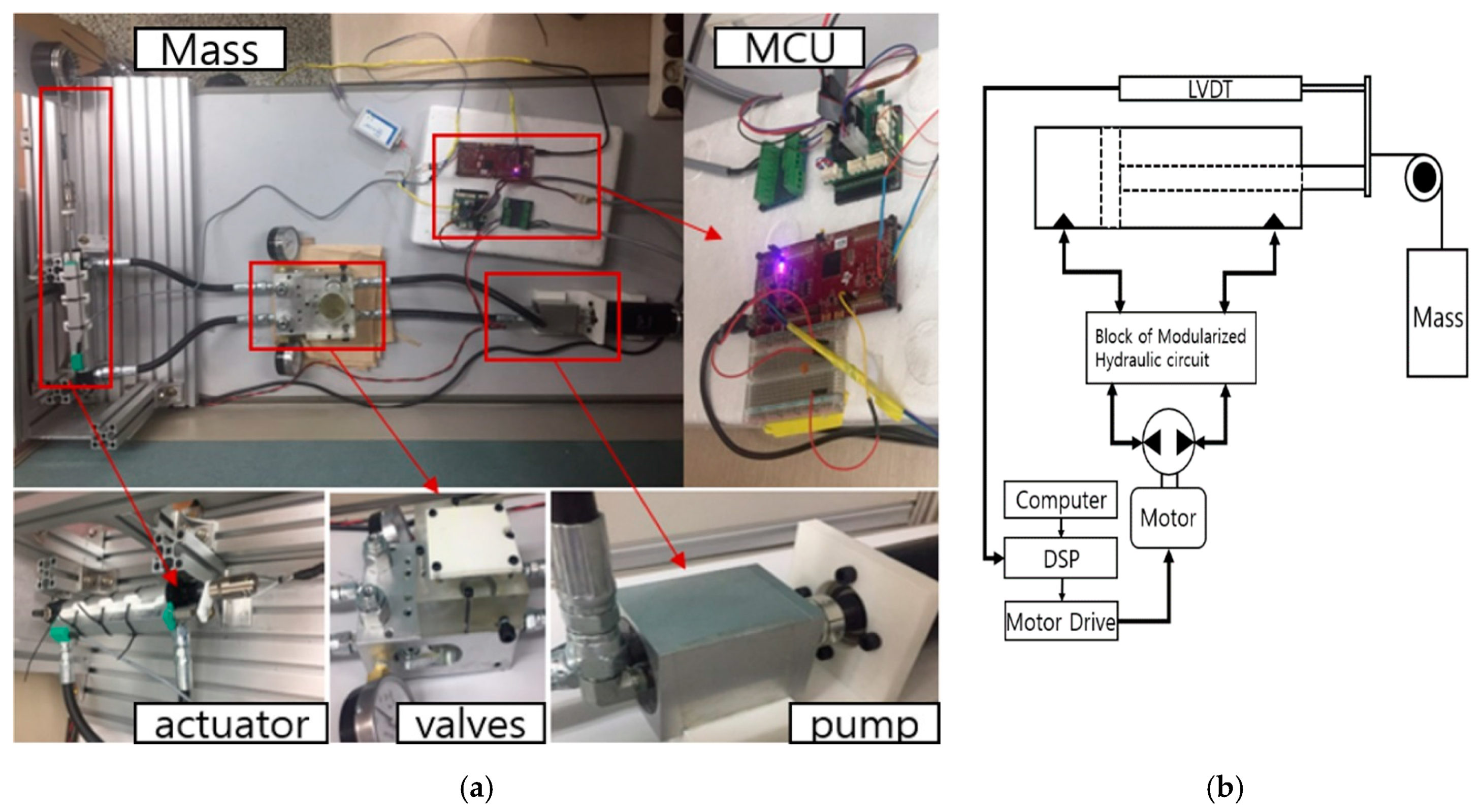
The proposed EHA consists of a brushless DC electric motor (BLDC), a bidirectional swash axial piston pump, directional valves, safety valves, a linear variable differential transformer (LVDT), and a 12 cm single rod actuator, which was selected after calculation according to the angle and length of the knee, as shown in
Figure 1. There are a total of six directional valves, two of which serve to maintain the constant pressure in the actuator. The remaining four valves are responsible for suction and draining. Two safety valves prevent damage to the actuator, and the pump serves to change the fluid direction.
Figure 2 shows a schematic of a swash axial piston pump with the pistons arranged at regular intervals in a cylinder block. There is a swash axial plate, a cylinder block, several assemblies of pistons with a slipper, a valve plate, and a shaft in the pump. The valve plate and swash axial plate are fixed, while the cylinder block is held against the valve plate.
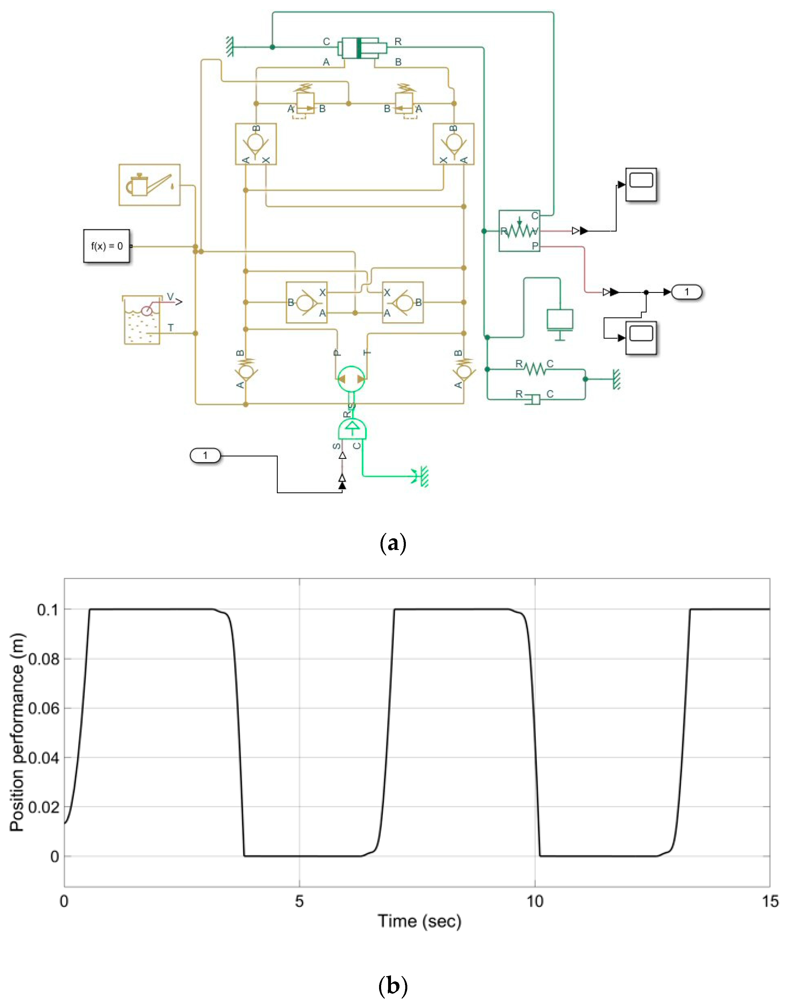
Safety and energy efficiency are important for EHA development considering a wearable robot. The proposed hydraulic circuit can prevent damage to the robot and increase the energy efficiency by two pilot check valves, which are placed on hydraulic lines in
Figure 3a. The valves maintain the pressure inside the actuator, regardless of an external environment. Simscape Fluid was used to verify the proposed hydraulic circuit.
Figure 3a shows what happens when 1500 rpm is given to the hydraulic circuit as the input value, and the result of the cylinder position is shown in
Figure 3b. The experimental results were gained from the parameters shown in
Table 1.
When the motor rotates the shaft, the displacement of the pump volumetric equation can be expressed as follows [
22,
23]:
where
is the volumetric displacement of the pump,
is the piston diameter in the cylinder block,
is the bore pitch radius of the cylinder block,
is the swash axial plate angle, and
denotes the number of pistons. The pump dynamics of the steady-state continuity equation can be written as in earlier work [
5]:
The pump is connected by two lines,
and
in the chambers.
is the forward flow to the
chamber,
is the return flow to the
chamber, and
and
are the internal and external leakage coefficients, respectively.
and
represent the pressure levels in the chambers, and
and
are the pump volumetric displacement and pump speed, respectively. Subtracting
from
determines the average load flow
:
where
is the total leakage coefficient, and
is the pressure difference between
and
. In the proposed electro-hydraulic actuator (EHA) lock circuit, four pilot valves are used to maintain the actuator pressure or to relieve the pressure. Two check valves are used to supply and return the hydraulic pressure, and two safety valves are used to protect the system from damage due to the occurrence of peak inspiratory pressure. The valve is fully closed when the pressure difference between
and
is lower than the cracking pressure. Two safety valves are referred to as pressure safety valves. The role of the safety valves is to reduce the pressure when it exceeds the valve pressure setting. When
or
reaches the cracking pressure, the valve passage area is increased gradually. The valve flow rate is determined by the pressure difference, which can be determined as in earlier work [
5]:
where
Here,
k is the linear constant of proportionality, and
is the pressure difference between the laminar and turbulent flows. Under pressure differential conditions,
and
k can be determined according to the following equations:
Assuming a constant forward flow to the
chamber from the
chamber, the valve flow equation is expressed as
The actuator is connected by the two-line chambers
and
with pressure valves, flow valves, and a bidirectional pump. The equation for the forward and return chambers in a single cylinder is shown below [
5,
19]:
flows into the cylinder, and
flows out of the cylinder from the initial cylinder. In addition,
and
are the areas of the forward chamber and the return chamber in the cylinder,
is the displacement of the cylinder,
is the initial volume of the cylinder, and
is the bulk modulus of the hydraulic oil.
and
are the volumes of the cylinder chambers. The single cylinder flow represents the addition of the flows in the lines. This is expressed as:
where
is the total force on the chambers, and
and
are the forces from
and
, respectively. Based on the equations of the pump flow, the cylinder flow, and the valve flow in the EHA circuit, the continuity equation for the forward chamber can be expressed as follows:
There is an assumption that the system’s pressure valve should be kept under the valve setting
of the two safety valves. Therefore,
The plant dynamics of the force balance equation for the cylinder is expressed as follows:
Here,
F,
M,
B,
K, and
denote the force, mass, damping coefficient, spring coefficient, and disturbance, respectively. From Equation (11), the differential Equation (12) is derived as shown below:
During normal operation, the system pressure valves
and
should be kept under the valve setting
of the two safety valves. Therefore,
where the Laplace transform applies:
If
spring loads can be disregarded; that is, K = 0 and
are the total coefficients of the system, and
B is the damping coefficient. A linear model of the pump, valve, and cylinder can be expressed as follows [
6]:
where
The proposed hydraulic circuit was tested to verify the performance of the pump-controlled EHA via Simscape Fluids in
Figure 3. The experimental results were gained from the input with the sine wave and the parameters shown in
Table 1. Before designing the controller, some work must be done to convert the transfer function of the EHA model to a state-space model. A third-order system with the transfer function is expressed as
where
In the pump-controlled EHA equation, the system has many model uncertainties at the beginning of the control operation due to the total leakage coefficient and the variable load. For example, the parameters M, , , and change with the variable loads in the single-load actuator, and the parameters and change when the oil temperature increases. For these reasons, the pump-controlled EHA system is considered to be a nonlinear system. Gradually increasing uncertainties can lead to inaccuracy or instability in the control system. Therefore, these nonlinear terms must be considered to minimize the effect of uncertainties when designing the controller.
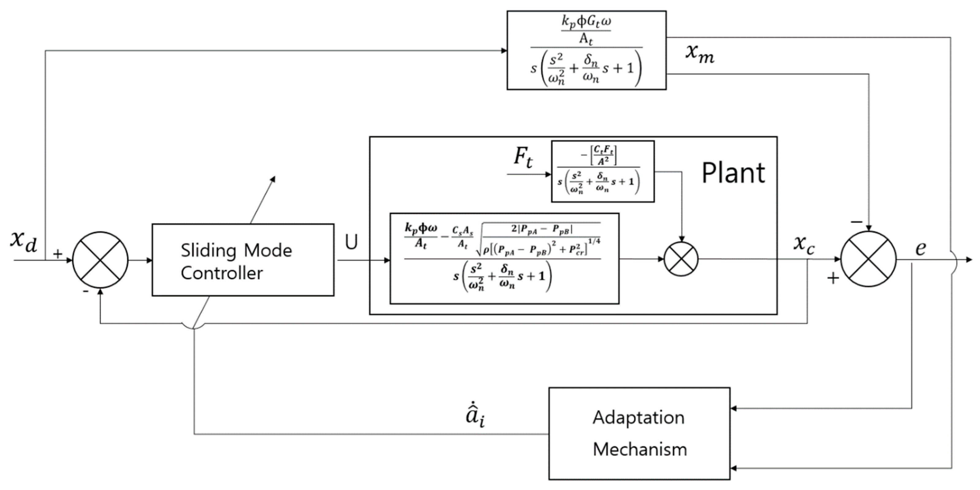
3. Design of an Adaptive Sliding Mode Control Scheme
An adaptive sliding mode control scheme is developed in order to minimize the model uncertainties for the pump-controlled EHA system using Equation (17). From Equation (17), the state-space model is easily formed via
The EHA plant model equation is developed by a first-order differential equation from the equation below:
Here,
u is its input and is equivalent to
,
x is the plant output, and
are constant, unknown plant parameters. Let the desired reference model equation be expressed by the first-order reference model:
where
r is the bounded reference signal, and
are constant parameters. During the first step of designing adaptive control, we use the following control law:
where
are the variable feedback gains. When we use the controller above (21) in the plant model equation above (19), the closed-loop dynamics become
In this case,
is not a perfect model; hence, the tracking error is expressed as
If we know the EHA model parameters,
,
,
,
, and
are equal to
,
,
,
, and
, respectively. Estimation of the error parameter can be done using the adaptation law and the ideal parameters,
. This is expressed as
where
Lemma 1 ([
24])
. For adaptation laws, two signals and e are considered. is a vector function of time, and v(t) is a measurable vector. If the vector chances according to
We apply Lemma 1 to obtain the adaptive law, and
is a positive constant. Hence,
e is globally bounded. As a result, the adaptive law can be expressed as follows:
Let
be the tracking error of variable
Owing to the third degree of the EHA, the surface
S (
t) can be expressed as follows [
24]:
Taking the derivative
S, we can determine the weighted sum of the position error and the velocity error:
Substituting the error of the parameter estimation (24) into the sliding condition (27), the sliding condition then becomes
and the control law becomes
where
Substituting the above control law (29) into the sliding condition (28) results in
where
are feedback gain parameters and lambda and
k are the design parameters.
is the boundary layer. When
is inside the boundary layer, a saturation function is used to prevent any sudden change of
u. At this stage, we analyze and demonstrate the stability of the system using the Lyapunov theory. We utilize the following Lyapunov function:
The derivative of V (32) becomes
where
Because the derivative of the Lyapunov function is less than zero, the adaptive sliding mode control scheme is globally stable.
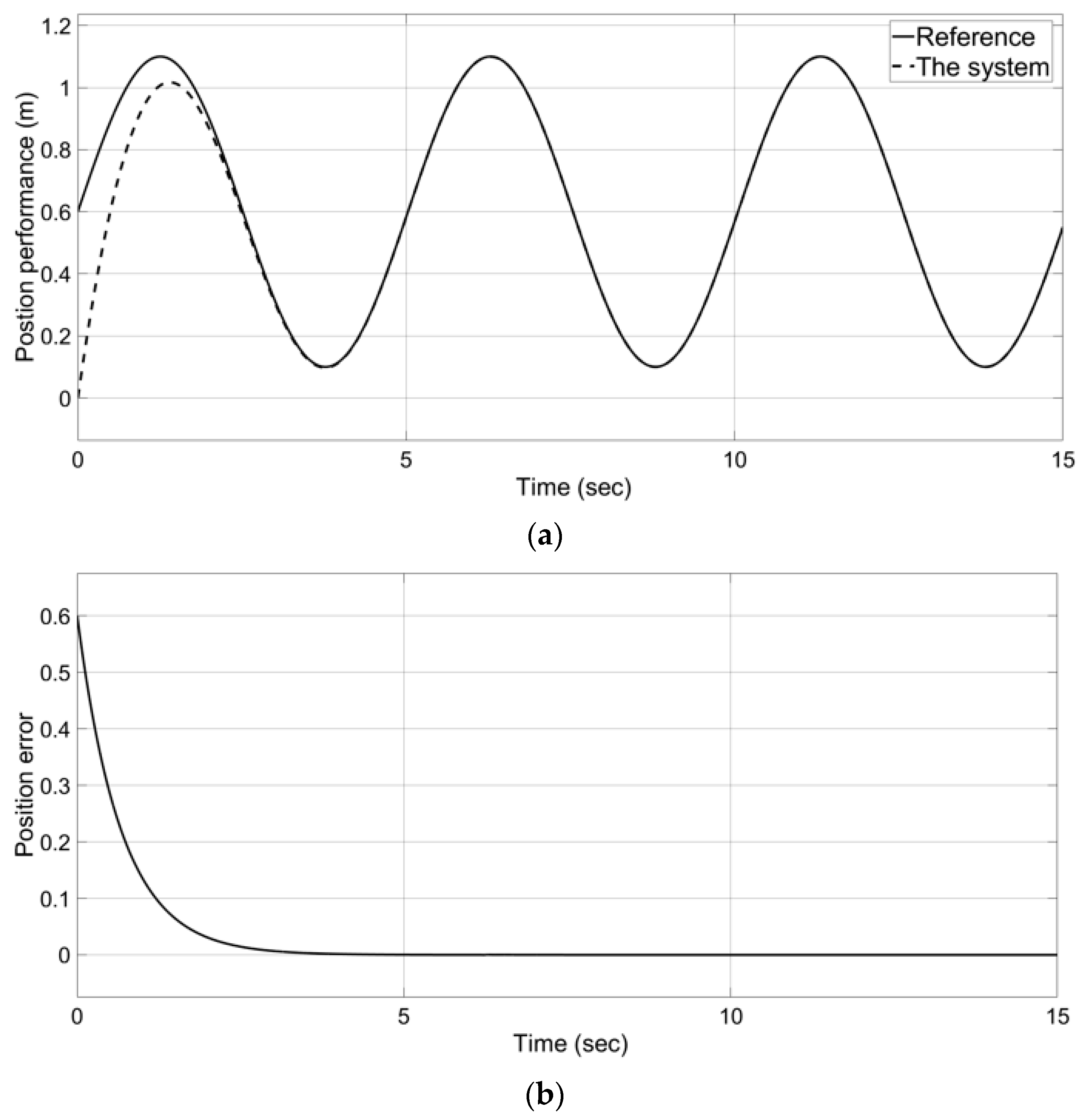
Figure 4 and
Figure 5 demonstrate that the proposed control reaches the target valve well after 2.5 s in Simulink.
4. Experimental Results
To verify the proposed controller, the experimental setup shown in
Figure 6 was used. The pump-controlled EHA system included the designed 0.8 cc swash axial piston pump, the modularized hydraulic circuit, a Gefran 125 mm linear displacement transducer, a 120 mm hydraulic cylinder, and a TI f28379d component as the main controller unit. The size of the pump is 5 cm in width, 6.8 cm in length, and 5 cm in height. The modularized hydraulic circuit included two check valves, four pilot valves, two safety valves, and a tank for suction and draining. The maximum allowable pressure of the hydraulic cylinder was 3.5 Mpa. The size of the modularized block is 9 cm in width, 12 cm in length, and 10 cm in height. The system clock on the TI f28379d device was 200 MHz, and the system interruptions occurred at programmed intervals of 0.001 s. The 400 W Maxon motor was connected to the pump. The detailed hydraulic parameters for the experiment are shown in
Table 2.
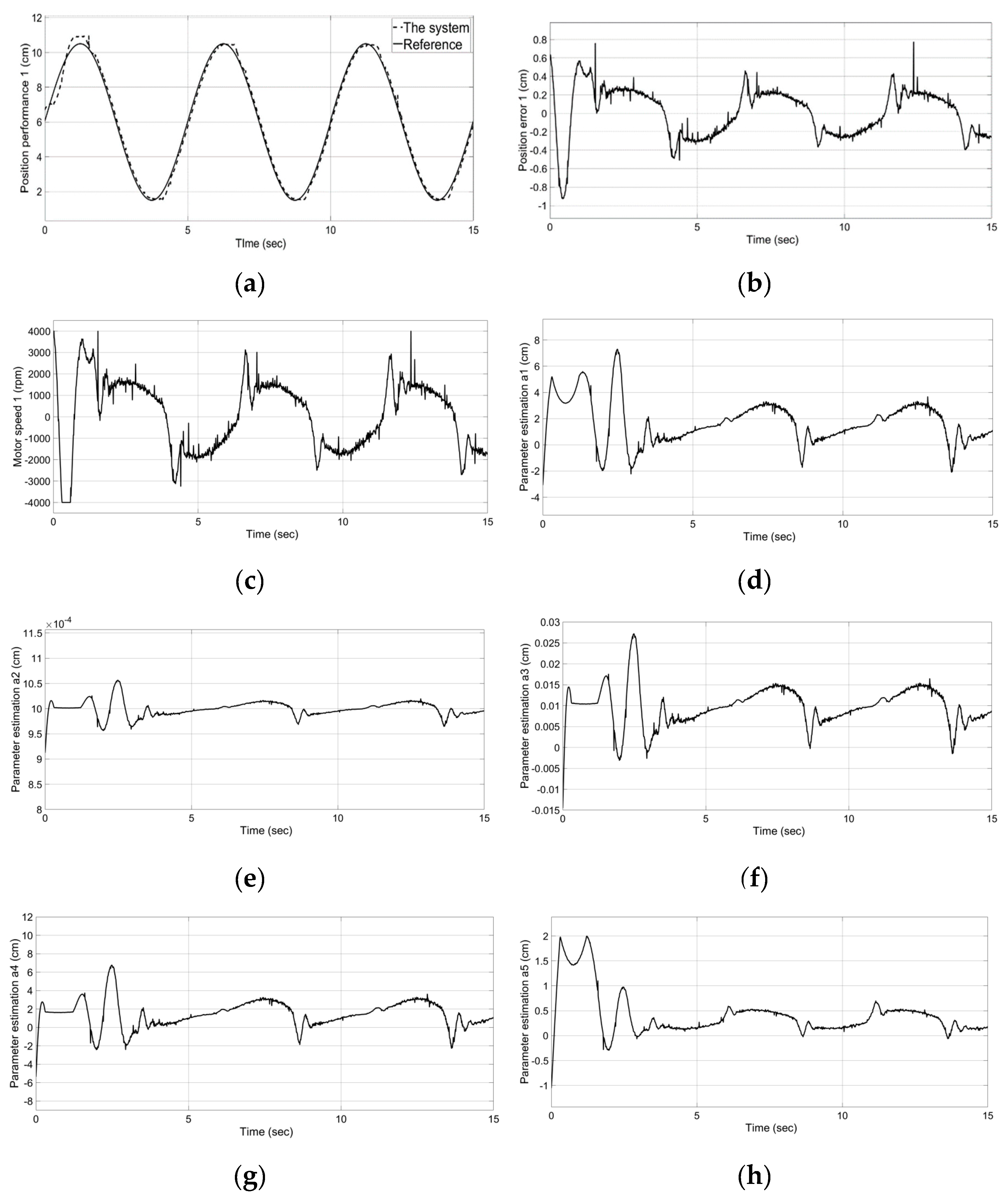
Figure 7 shows that the pump-controlled EHA system without a mass performed well. At the beginning of the experiment, we set the different start locations of the input value and desired value because we wanted to see how well and quickly the proposed system tracks the desired value. In the experiment, the design parameters of
, K, and lambda were set by 0.8, 0.35, and 10, respectively. The cylinder moved forward and backward by 10 cm at five-second intervals. The goal of the proposed controller shown in
Figure 7a is to achieve suitable tracking to the sine wave reference, although it was inaccurate at the beginning of the control operation for two seconds. However, due to the rotational moment of inertia and the pumped controlled characteristics, especially the slow response due to the large volume, it was difficult to track accurately and completely in this manner when changing the direction of the cylinder. Therefore, as shown in
Figure 7b, errors of 2 mm above and below occurred in the repetitive error section. To reduce this type of error, the motor speed rpm in the plant command was considered, as shown in
Figure 7c. Because the maximum allowable speed of the Maxon motor is 4800 rpm, a limit was set here, at 4000 rpm, to ensure the safety of the motor. When entering the adaptive sliding mode surface, the motor speed was maintained at 1500–1700 rpm.
Figure 7d–h show the feedback gain parameters in cm units. At the beginning of the control operation, the system was unstable and was seen to change significantly. Subsequently, the system became stable and maintained a constant value.
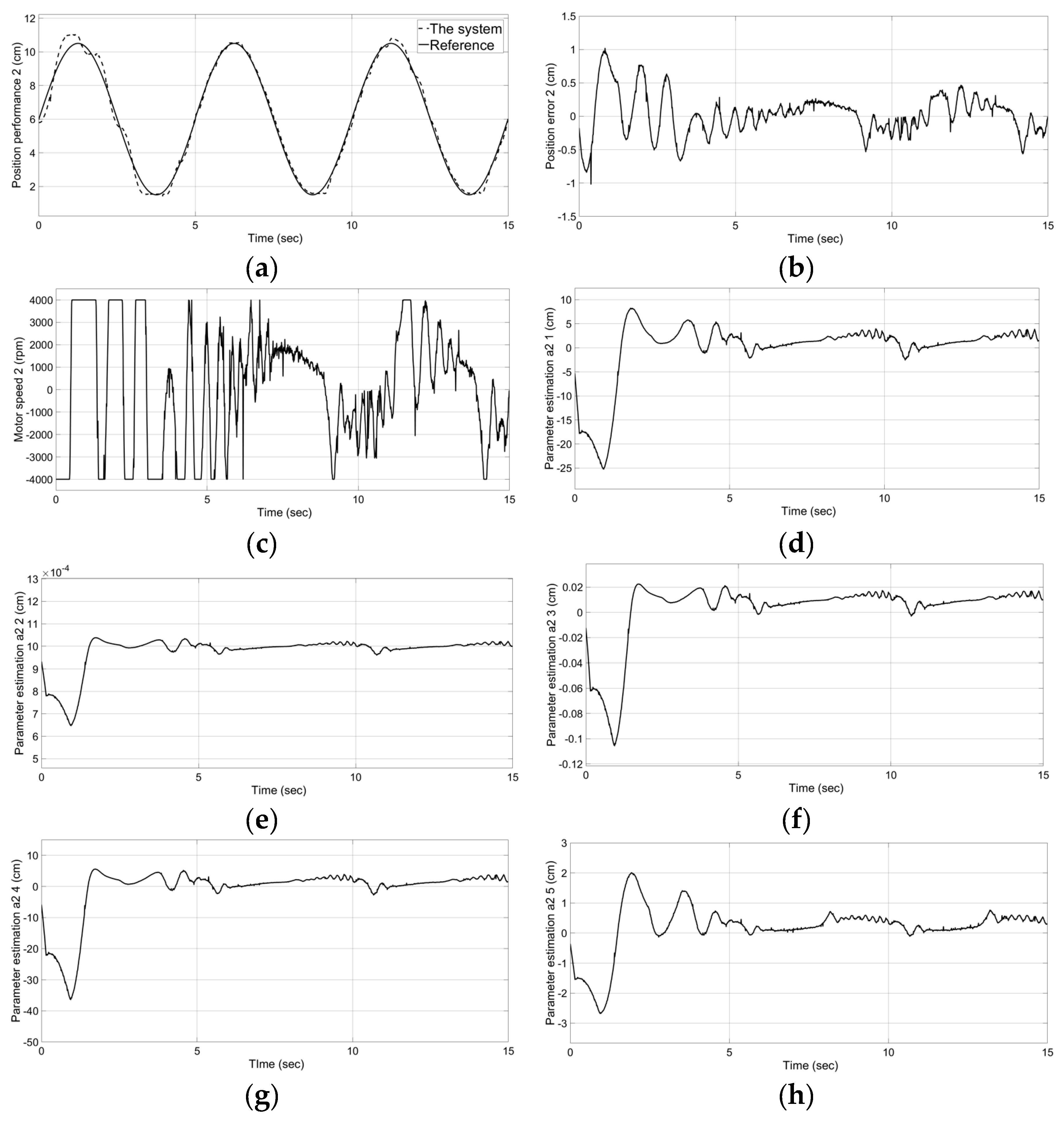
Figure 8 shows that the pump-controlled EHA system with the 15 kg mass performs well. We applied the same parameter gains shown in
Figure 7 and confirmed the following results. Compared with
Figure 7a, the system stabilization time of
Figure 8a is delayed by two seconds. However, past that point, we confirmed that the system tracks the desired input well. Due to the moment of inertia by the mass, the instantaneous error of about 4 mm occurred at 11 s, as shown in
Figure 8b. In addition, compared with
Figure 7c, we confirmed that the motor speed increases due to the mass, as shown in
Figure 8c.
Figure 8d–h indicate that large fluctuations arise until the estimation parameters stabilize due to the mass.


