Article

A Novel MPC with Actuator Dynamic Compensation for the Marine Steam Turbine Rotational Control with a Novel Energy Dynamic Model

College of Automation, Harbin Engineering University, Harbin 150001, China
*
Author to whom correspondence should be addressed.
Processes 2019, 7(7), 423; https://doi.org/10.3390/pr7070423
Submission received: 4 May 2019 / Revised: 27 June 2019 / Accepted: 28 June 2019 / Published: 3 July 2019
(This article belongs to the Special Issue Dynamic Modeling and Control in Chemical and Energy Processes)

Abstract

:
The conventional modeling method of the marine steam turbine rotational speed control system (MSTRSCS) is based on Newton’s second law, constructing the mechanical equations between the rotational acceleration and the resultant torque. The disadvantages of this are nonlinearity, a complex structure and an infinite point of discontinuity in the rotational acceleration when the rotational speed is close to 0. Taking the kinetic energy of MSTRSCS as the output variable by using the kinetic energy theorem in this paper, we convert the complex nonlinear model of MSTRSCS into a linear one, since kinetic energy and rotational speed are homeomorphic. Model predictive control (MPC) adopts a discrete-time model, whereas the real system is time-continuous. Hence, poor performance is obtained in the real system when the time-discrete control law is applied to the MSTRSCS through the actuator. In case of high requirements for system accuracy and control performance, conventional MPC (CMPC) cannot meet the engineering requirements. In order to lessen the impact of this phenomenon, this paper proposes a novel MPC with actuator dynamic compensation (ADCMPC), in which the dynamics of the actuator are quantified and the system performance is improved. Compared with other control techniques such as CMPC, the performance of the ADCMPC strategy in MSTRSCS is successfully validated.

1. Introduction

The pressurized marine steam power plant is the key to ensuring the completion of shipping and navigation tasks [1]. MSTRSCS is the main form of marine power equipment. It has the advantages of a high single power supply, high reliability, economy, a light weight, small volume and convenient maintenance [2]. In order to ensure the stability, rapidity and correctness of the ship’s navigation, the pressurized marine power control system needs a further intelligent level, which can be realized by applying high-performance control strategies to the MSTRSCS [3].
At present, the literature on the steam turbine control has the following characteristics: (1) most of the available reports on steam turbine control concentrate on the power station steam turbine [4], and there are few studies on marine steam turbine control problems. The control task of the power station steam turbine is to ensure output power at the desired value. Therefore, steady-state characteristics of the power station steam turbine are more thoroughly investigated [5]. However, the control task of the marine steam turbine is to guarantee its rotational speed at the desired value [6]. Furthermore, compared with the power station steam turbine, much attention is paid not only to the steady-state characteristics but also to its dynamic characteristics [7]; (2) there are few reports that only study the steam turbine control problems [4], and most of the current studies are about steam power plants, and the steam turbine is mentioned in the literature as a part of the steam power system [8,9,10]; (3) there is a modeling problem for the steam turbine [11]: due to the existence of heat transfer and conversion of steam internal energy during the operation of the steam turbine system, not only the structure but also the operating principles of the steam turbine are extremely complex, which adds difficulty in mathematical modeling and controller design [12,13]. In the course of navigation, the conditions of the ship as well as the parameters of the turbine will change frequently [14]. For example, when the ship is sailing at sea, it will be disturbed by waves and currents [15]. Meanwhile, the navigation speed of the ship will change frequently according to the actual situation; sometimes it is necessary to sail at full speed, and sometimes at low speed or even with reverse navigation [16]. Whether a ship can complete its task in time and accurately depends to a great extent on the performance of the steam turbine control system. Therefore, MSTRSCS needs to have strong robustness and good dynamic characteristics, and it is very important to research the rotational speed control strategy of marine steam turbines [2].
In the past 40 years, MPC has been widely used in the field of industrial process control and has achieved great success [17]. MPCs are mainly divided into two categories. The first is classical MPC, based on a linear mathematical model. Richalet et al. proposed model predictive heuristic control (MPHC) and model algorithmic control (MAC) in 1978 [18,19]. Then, in 1980, Culter et al. proposed dynamic matrix control (DMC) [20]. Garica’s theory enables people to analyze predictive control systems from the perspective of structure and understand the operational mechanisms of model predictive control [21]. In 1986, Kuntze et al. proposed predictive functional control (PFC) [22]. In 1987, Clarke et al. proposed generalized predictive control (GPC) based on the controlled autoregressive integral average sliding model (CARIMA). These methods have low requirements as system models, and the algorithms are simple and easy to implement, showing good control performance in actual industrial control [23,24]. The other category of MPCs is nonlinear model predictive control (NMPC) based on the nonlinear model; this kind of control strategy is more complex, and the popular control algorithms are as follows: model predictive control terminal zero constraints [25,26,27], model predictive control with terminal state set constraints [28,29], model predictive control with terminal cost function [30,31,32], and model predictive control with both terminal state set constraints and terminal cost function [33,34,35,36,37,38,39,40,41,42,43,44]. Although NMPC has been developed in academia for many years, it still requires development in practical engineering.
Nowadays, linear MPC [45] has been widely used in practical engineering, but the problem is that most MPCs adopt a discrete-time mathematical model, which can reduce the amount of calculation, the computational complexity and computational difficulty, but inevitably affects the response time of the actual system, resulting in the system’s dynamic characteristics being overly conservative. For a practical system, settling time usually takes several sampling periods (mTs) before reaching a steady state. In order to reduce the computational complexity, the MPC algorithm tries to make the value of the sampling period Ts as close as possible to the upper limit of the Shannon sampling theorem; that is, the time mTs required for the system to reach a steady state will be very large, resulting in a large settling/response time for the actual system, and this cannot enable the system to have a fast response characteristic. If we simply reduce the sampling period Ts—for example, by taking the sampling period value as close as to the dynamic time constant of the actuator—the control accuracy will be affected by the dynamic characteristics of the actuator, which will be explained in detail in Section 2. The purpose of this paper is not only to make the marine steam turbine run steadily, but also to make the marine steam turbine have faster dynamic response characteristics. Of course, there are also predictive control theories based on the continuous-time model. In 2000, Gawthrop P.J. proposed a model predictive control scheme based on the continuous-time model: predictive pole-placement (PPP) control [46,47,48]. In 2018, Mehdi Hosseinzadeh and Emanuele Garone [49,50,51] introduced a novel Explicit Reference Governor for continuous-time systems, which constrained in-between MPCs and anti-windup control schemes. Additionally, there is also a great deal of attention paid in [52] to introducing the continuous-time model predictive control theory.
The rest of the paper is organized as follows: Section 2.1 briefly introduces the marine steam turbine and the modeling method used in the paper, Section 2.2 outlines the shortcomings of the conventional MPC with actuator dynamics, Section 2.3 is the mathematical analysis of conventional model predictive control, and Section 2.4 designs a novel model predictive controller with actuator dynamic compensation. In Section 3, the simulation settings and results are summarized, and the effectiveness of the proposed method is verified. Then, in Section 4, future work is summarized.

2. Materials and Methods

2.1. Marine Steam Turbine Rotational Control Modeling

The steam turbine is one of the most important power conversion devices in the marine power plant [1]. It is a rotary prime mover that converts the thermal energy of the steam into mechanical energy. Compared with reciprocating steam engines and diesel engines, it has the advantages of high power, high speed, smooth operation, small size, small weight and high efficiency [2]. Therefore, it has been widely used in the marine transportation industry [53].
The accelerated motion model of ship can be obtained by Newton’s second law [54]:
d V d t = ( F p r o p 1 + F p r o p 2 + + F p r o p n ) ( 1 t d ) F d r a g m m a
where V denotes the ship navigation speed, m/s; Fpropi is the ith propeller thrust, N; td is the dimensionless thrust deduction coefficient; Fdrag is the backward drafting force of a ship when it is sailing; m is the quality of the ship, kg; and ma is the dimensionless additional mass coefficient of the ship.
According to the accelerated motion model of the ship, we know that the ship is navigated by the propeller thrust, and the thrust required at different navigation speeds is different [55]. The propeller is driven by a marine steam turbine, and the propeller thrust is closely related to the rotational speed of the steam turbine [56]. Therefore, the control performance of MSTRSCS is extremely important.
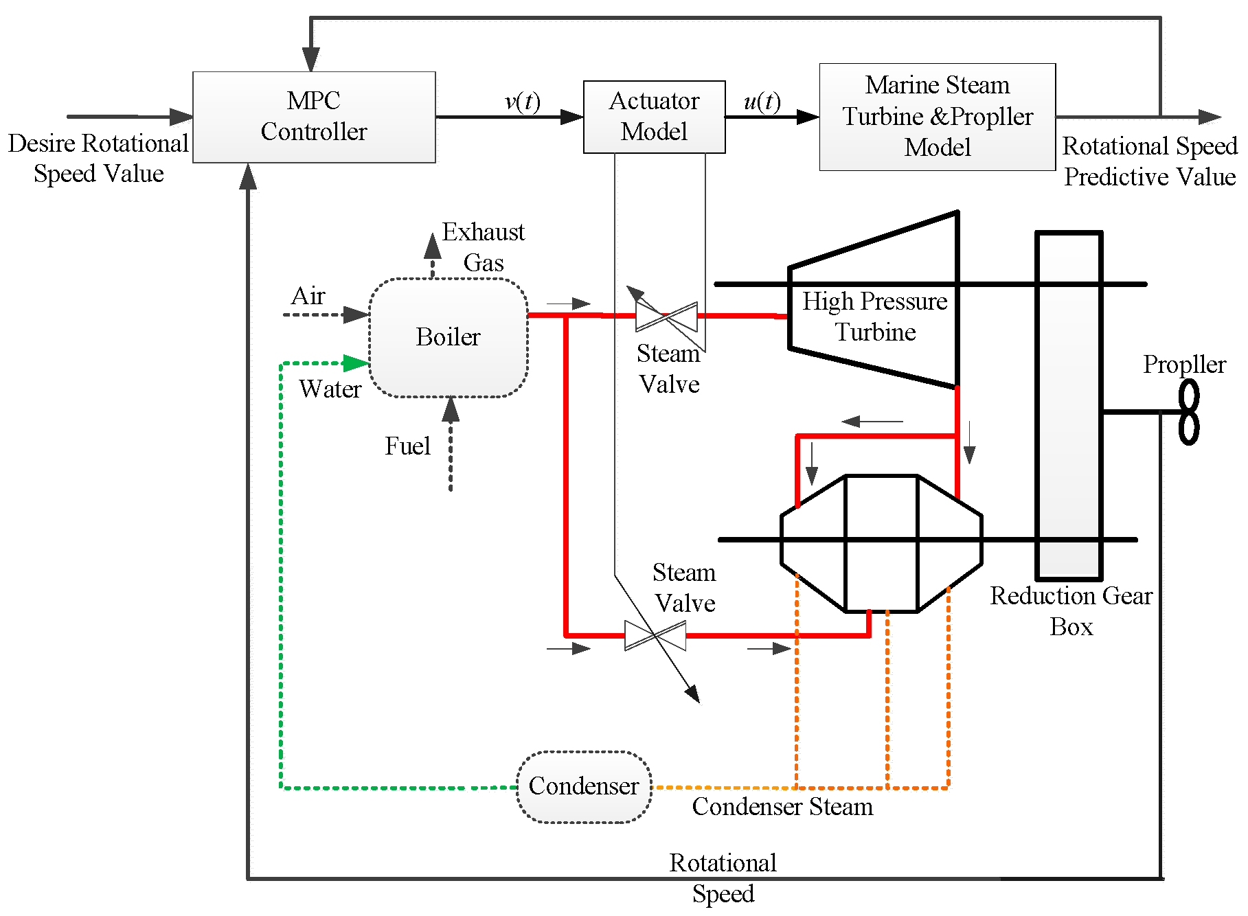
A marine steam turbine consists of two cylinders: a high-pressure cylinder and a low-pressure cylinder [7]. The two cylinders are placed in parallel and connected through a connecting pipe, as shown in Figure 1. After working in the high-pressure cylinder, the steam is sent into the low-pressure cylinder to continue the expansion work; there is also a reversing steam turbine which is controlled by a special reverse control valve, as shown in Figure 1.
The marine steam turbine is a kind of condensing steam turbine which changes the steam mass flow by controlling the opening of the fast governing steam valve [7] and then realizes the adjustment of the marine steam turbine rotation speed. The rotational speed of the power station steam turbine is usually constant [57], while the rotational speed of the marine steam turbine varies with the ship’s navigational speed; that is, the dynamic process of MSTRSCS will occur frequently in the operation [58]. Therefore, the control strategy of the marine steam turbine rotational speed should not only ensure the steady characteristics of the system but also consider the dynamic characteristics of the turbine.
Therefore, according to the kinetic energy theorem, we can determine that the derivative of the kinetic energy of MSTRSCS is equal to the sum of all of the powers at that moment:
dEk(t)/dt = ∑P = PT(t) − PP(t)
where Ek(t) denotes the rotational kinetic energy of MSTRSCS, dEk(t)/dt is derivative the of Ek(t), PT(t) is the steam expansion work power in the marine steam turbine, and PP(t) is the load power of the propeller.
Denoting the whole rotary inertia of MSTRSCS as J, the rotational speed of MSTRSCS as nt(t) and the mass flow of the steam intake to the turbine as u(t), it is assumed that the resistance that the propeller receives during rotation is proportional to the rotational speed nt(t).
The mathematical model of MSTRSCS can be obtained as follows:
Ek(t) = Jn2t(t)/2
PT(s) = KTu(t)
According to [56], the load torque of propeller can be expressed as follows:
TP = KQρD5n2t(t)
According to the definition of power in physics, the load power of propeller can be obtained as follows:
PP = TPnt(t) = KQD5n3t(t)
where KQ is the dimensionless torque coefficient; ρ denotes the sea water density; nt is the rotational speed of the propeller; and D is the diameter of the propeller. The maximum rotational speed nmax of the system is a known constant value. Taking κ = KQnmaxD5, the difference Δκ = KQ(nmaxnt(t)) can be added to the model as interference in the simulation. Thus,
PP(t) = κn2t(t)
where KT denotes the total work done by the expansion of the unit mass steam in the marine steam turbine; TT is the time constant of the expansion work process in the marine steam turbine; and κ is the drag coefficient of the propeller. Substituting the above equations, we obtain the overall mathematical model of the system:
J 2 d ( n t 2 ( t ) ) d t = P T ( t ) κ n t 2 ( t )
The MSTRSCS represented by the above formula is a nonlinear model. To simplify the model, take n2t(t) as a variable and let y(t) = n2t(t):
J 2 d y ( t ) d t = K T u ( t ) κ y ( t )
The Laplace transform of the above equation is used to obtain the transfer function of MSTRSCS:
J 2 s Y ( s ) = K T U ( s ) κ Y ( s )
Finally, the model of MSTRSCS can be obtained as follows:
Y ( s ) U ( s ) = K T J 2 s + κ

2.2. Formulation of the Control Problem

For the time-discrete mathematical model, the system state, output and control input are considered to be invariable within a sampling period. However, the actual system is time-continuous: the state, output, and control input of the system are time-varying. Therefore, the time-discrete model calculates and predicts system parameters more slowly than the actual system and with less information.
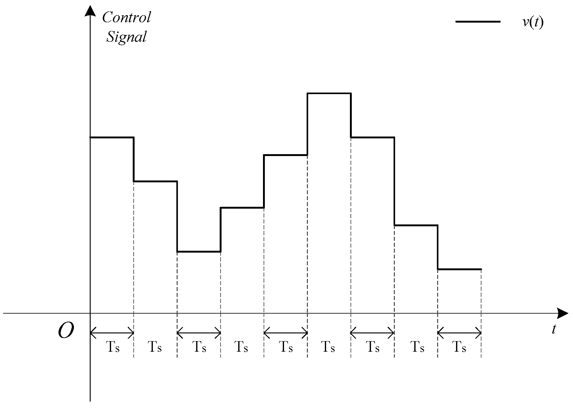
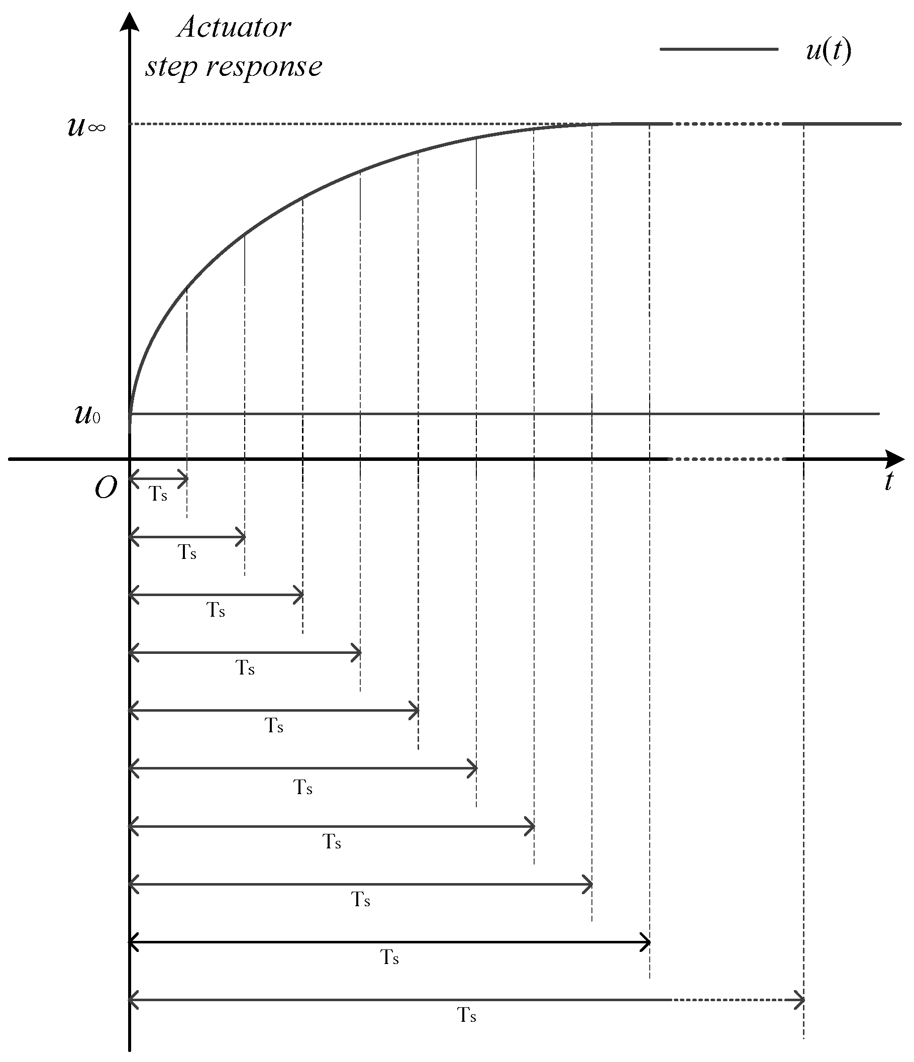
According to Figure 2, in one sampling period, the control signal generated by the MPC controller is a step signal, and the control signals in different sampling periods constitute a stair-stepping signal. However, the dynamic of the actuator is time-continuous. The control signal v(t) generated by the controller does not directly act on the plant, but acts on the actuator; i.e., the control signal v(t) acts as the actuator’s input signal. The actuator will produce an output effect u(t) as the response to v(t), and u(t) is not a stair-stepping signal, as shown in Figure 3 and Figure 4. If the sampling period Ts and the actuator time constant T0 are much too close, the dynamic performance of the system will be deteriorated.
According to engineering experience [52], the actuator can be treated as a first-order damp element; that is, the mathematical model of the actuator is
u ( s ) v ( s ) = G 1 ( s ) = 1 T 0 s + 1
where the T0 is the time constant of the actuator.
For the actuator, assuming that the initial value is v0, then the actuator’s response curve to the step signal r(t) = u is shown in Figure 4; u(t) is the output of the actuator and acts directly on the plant.
u ( t ) = e t T 0 u 0 + u ( 1 e t T 0 )
As shown in Figure 4, when the time tends towards infinity, the actuator output u(t) is infinitely close to the value of the step signal r(t), or it can be said that the output u(t) of the actuator is close to the step signal r(t) when the time is large enough, which can be expressed as
lim t u ( t ) = u
However, when the time is very small, the output u(t) of the actuator is far less than that of the step signal r(t), while in the MPC, the sampling period Ts is unlikely to be much too large due to the Shannon sampling theorem. This will lead to a large deviation between u(t) and v(t) in the beginning of a sampling period, as shown in Figure 5. In Figure 5, the time constant of the actuator T0 = 1 s, and the sampling periods Ts are 20 s, 10 s, 5 s, and 3 s, respectively. The control signal uses a set of positive random step values. As the sampling period Ts decreases, the deviation between u(t) and v(t) increases, which in turn affects the performance of the controller. For example, the output of the control system will be greatly overshot; the dynamic characteristics of the entire control system can become very poor, which can lead to instability of the system.
In the time period [(k − 1)Ts ~ kTs] corresponding to the kth sampling period, the output u(t) of the actuator can be calculated by
u ( t ) = u ( k 1 ) + ( v ( k ) u ( k 1 ) ) 1 ( K T 0 s + 1 ) = u ( k 1 ) + ( v ( k ) u ( k 1 ) ) ( 1 e t ( k 1 ) T s T 0 ) = v ( k ) ( v ( k ) u ( k 1 ) ) e t ( k 1 ) T s T 0
The CMPC exhibits good steady-state characteristics when applied to the marine steam turbine. However, the CMPC fails to achieve a marine steam turbine with excellent dynamic performance. According to the previous analysis of the dynamic characteristics of the actuator, it can be determined that the sampling period Ts regarding the MPC cannot be too small or u(t) greatly deviates from v(t), and the stability of the whole system is thereby affected. However, if the sampling period of the system takes a large value, the response time of the system will be too long to result in good dynamic characteristics for the marine steam turbine. Therefore, the CMPC is not suitable for marine steam turbines, which needs to be improved.

2.3. CMPC Algorithm

Based on the previous analysis, the current popular control algorithms all have good static characteristics. The difference between them is that the dynamic characteristics are highly different. The purpose of the actuator dynamic compensated model predictive control algorithm is to improve the dynamic characteristics of the CMPC. In practical engineering applications, many systems are built before their specific dynamic and static characteristics are analyzed. Then, the controller is designed according to the actual engineering requirements. In CMPC design, the actual system actuator dynamic response characteristics will not be considered, which has a negative impact on the control performance. In order to achieve control performance with excellent dynamic response characteristics, we must obtain the analytical expression of the dynamic characteristics of the actuator, from which can we quantify the influence of the dynamic characteristics of the actuator on the system output, not only improving marine steam turbine control performance, but also obtaining better dynamic characteristics.
In the CMPC algorithm [52], the dynamic process of the actuator’s response to the control signal v(t) is not considered, and the actuator of the plant is treated as a proportion component, in which the actuator is ignored. In order to facilitate the following description, the following provisions are made: v(k), y(k) and u(k) refer to the controller signal, the system output and the actuator output at the end of the sampling period, respectively. Let K = KT, T = J/2κ, according to Equation (5):
G ( s ) = Y ( s ) U ( s ) = K T J 2 s + κ = K T s + 1
y ( t ) = 1 ( G ( s ) U ( s ) ) = 1 ( K T J 2 s + κ ) * 1 ( U ( s ) e τ 1 s )
According to the convolution theorem, the convolution calculation formula can be expressed as follows:
f ( t ) g ( t ) = 0 t f ( x ) g ( t x ) d x
according to the inverse Laplace transform of G(s) and U(s), respectively. Substituting Formula (12) into Equation (11), y(t) can be further outlined:
1 ( K T s + 1 ) = K T e t T , 1 ( U ( s ) e τ 1 s ) = u ( t τ 1 )
y ( t ) = 0 t g ( t τ ) u ( τ ) d τ = K T e t T 0 t e τ T u ( τ τ 1 ) d τ
In the discretization of y(t), the sampling period is Ts. The system output y(kTs) at the moment of kTs is denoted as y(k) [17,52]. Meanwhile, in the discrete model, y(k) also represents the system output in the kth sampling period [(k − 1)Ts ~ kTs]. According to Formula (13), y(k) and y(k + 1) in the kth and (k + 1)th sampling period can be expressed as:
y ( k ) = y ( k T s ) = K T e k T s T 0 k T s e τ T u ( τ τ 1 ) d τ
y ( k + 1 ) = y ( T s + k T s ) = K T e T s + k T s T 0 T s + k T s e τ T u ( τ τ 1 ) d τ
Substituting (14) into (15), we acquire the relationship between y(k) and y(k + 1), which is shown as follows:
y ( k + 1 ) = K T e T s + k T s T ( 0 k T s e τ T u ( τ τ 1 ) d τ + k T s T s + k T s e τ T u ( τ τ 1 ) d τ )
y ( k + 1 ) = e T s T K T e k T s T 0 k T s e τ T u ( τ τ 1 ) d τ + K T e T s + k T s T k T s T s + k T s e τ T u ( τ τ 1 ) d τ
y ( k + 1 ) = e T s T y ( k ) + K T e T s + k T s T k T s T s + k T s e τ T u ( τ τ 1 ) d τ
In Equation (16), both e−(Ts/T) and K/T are known as constants; y(k) is also determined during the (k + 1)th sampling period. Only the definite integration term is unknown and needs to be calculated. As indicated above, in the MPC algorithm, the signal u(k) of the controller in each sampling period is a step signal. That is, u(ττ1) in the definite integral term of Equation (16) is a time-independent constant value in the (k + 1)th sampling period, which can be seen in Figure 2. Additionally, u(ττ1) can transpose to the outside of the definite integral term:
k T s T s + k T s e τ T u ( τ τ 1 ) d τ = e T s + k T s T e k T s T
By substituting Equation (17) into Equation (16), we can obtain the time-discrete mathematical model of MSTRSCS. For convenience of description, the control action u(kTsτ1) is simplified as follows:
u ( k T s τ 1 ) = u ( k τ 1 T s )
y ( k + 1 ) = e T s T y ( k ) + u ( k T s τ 1 ) K e T s + k T s T ( e T s + k T s T e k T s T ) = e T s T y ( k ) + u ( k T s τ 1 ) K ( 1 e T s T ) = e T s T y ( k ) + K ( 1 e T s T ) u ( k τ 1 T s )
The relevant parameters in (18) can be denoted as follows: E = −F = e−(Ts/T), H = (1 − e−(Ts/T)) and S = τ1/Ts. The discrete-time model of the marine steam turbine speed control system is finally obtained as follows:
y ( k + 1 ) + E y ( k ) = H u ( k S )
Sometimes, in order to increase the stability of the system, the increment operator ( Δ = 1 − z−1) is introduced to both sides of Equation (19) [17,52]; then, the incremental model Δy(k) is obtained by increasing quantization, in which an integral component is introduced to MSTRSCS to enhance the stability and improve the steady-state characteristics of the whole system.
Take the incremental model Δy(k + 1) of MSTRSCS as an example:
Δy(k + 1) = (1 − z−1) y(k + 1) = y(k + 1) − y(k)
Therefore, the incremental form of Equation (19) can be obtained:
Δ y ( k + 1 ) + E Δ y ( k ) = H Δ u ( k S )
Δ y ( k + 1 ) = F Δ y ( k ) + H Δ u ( k S )

2.4. Actuator Compensation Predictive Control Algorithm

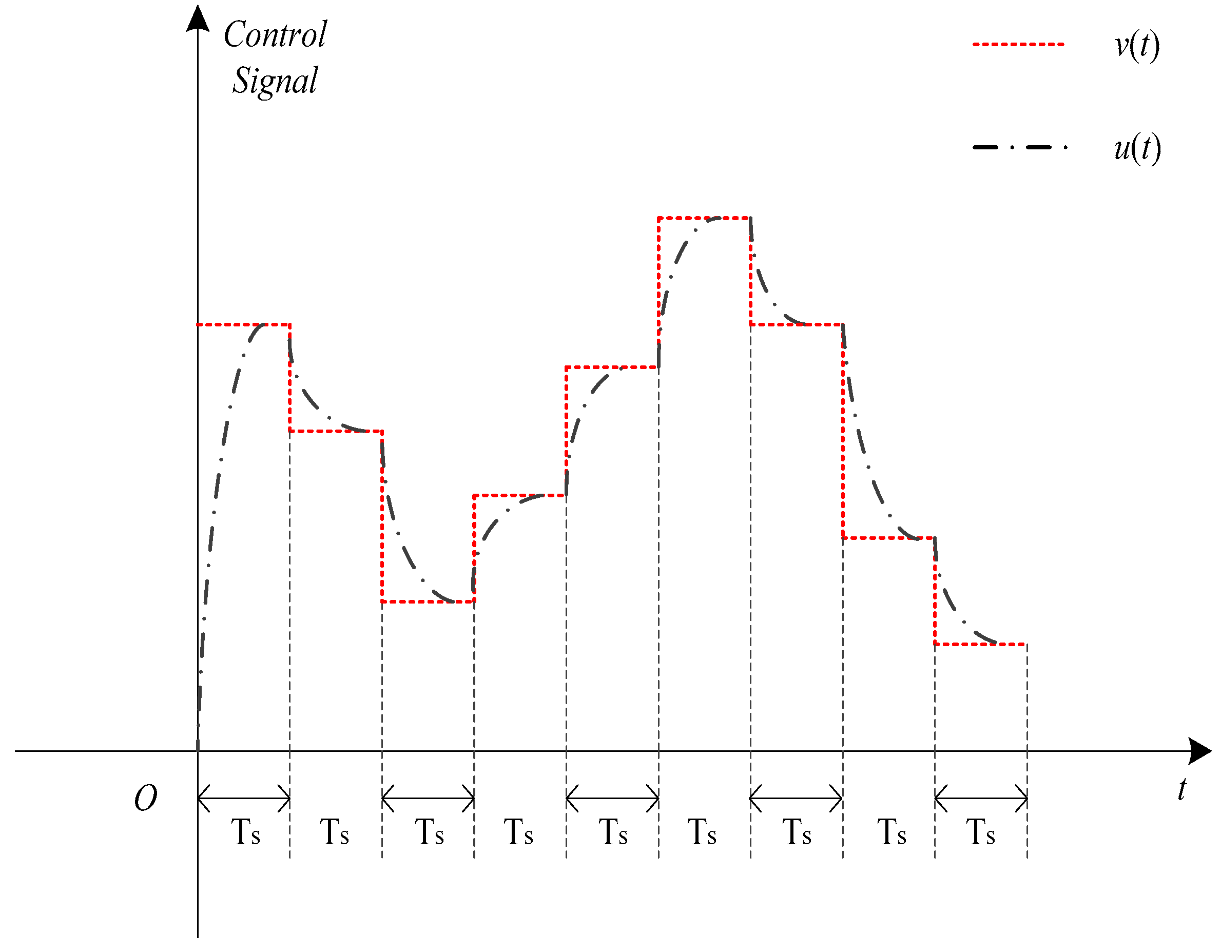
In the derivation process of the CMPC algorithm, the dynamic process of the actuator’s response to the control signal v(t) is not considered, and the actuator of the system is treated as a proportion link so that the output of the actuator is u(t) = v(t); otherwise, the actuator is ignored and it is considered that the controller signal v(k) acts directly on the actual system. In addition, in the process of calculating the definite integral of Equation (16), u(ττ1) is considered as a time-independent constant value. However, in Section 2.2, we determined that the rapid response characteristics of MSTRSCS have a very large relationship with the actuator. Since the actuator is a first-order inertia component, the controller signal v(t) is a step signal when the controller signal v(t) is sent into the actuator, and the actuator generates output u(t), which is directly sent to the marine turbine, making it rotate or change speed. However, u(t) obtained by v(t) has a large deviation from v(t), and the deviation value increases as the sampling period decreases, as shown in Figure 6. According to Equation (10), in the time period [(k − 1)Ts ~ kTs] corresponding to the kth sampling period, u(t) is expressed as follows:
u ( t ) = ( 1 e t - ( k - 1 ) T s T 0 ) v ( k ) + e t - ( k - 1 ) T s T 0 u ( k 1 )
The difference between the u(t) of the actuator and the control signal v(t) can be outlined as follows:
u ( t ) v ( t ) = ( 1 e t - ( k - 1 ) T s T 0 ) v ( k ) + e t - ( k - 1 ) T s T 0 u ( k 1 ) v ( k ) = e t - ( k - 1 ) T s T 0 ( u ( k 1 ) v ( k ) )
where, in the kth sampling period, v(t) is a step signal, a time-independent constant; that is, v(t) = v(k). On the other hand, u(k − 1), as the output of the actuator during the previous sampling period, which is a known constant at this time. Equation (23) indicates that during the kth sampling period, the difference between the control action u(t) of the actuator and the control signal v(k) becomes smaller and smaller, exponentially decaying. This shows that the sampling period Ts is critical; if the value of Ts is relatively large, the difference between the control action u(t) and the control signal v(k) has little effect on MSTRSCS. On the other hand, if Ts is small, the difference between the control action u(t) and the control signal v(k) has a great influence on MSTRSCS, and even affects the steady-state characteristics of the system. Therefore, in order to enable MSTRSCS to have good dynamic response characteristics, the dynamic characteristics of the actuator must be compensated. For this reason, a novel MPC algorithm with actuator dynamic compensation is proposed.
According to Formula (16), y(k + 1) in the (k + 1)th sampling period can be expressed as
y ( k + 1 ) = e T s T y ( k ) + K T e T s + k T s T k T s T s + k T s e τ T u ( τ τ 1 ) d τ
where the parameters e−(Ts/T) and K/T are known constant values, and y(k) is a known constant in the (k + 1)th sampling period. The definite integral term in Equation (24) needs to be calculated. Equation (22) is substituted into Equation (24) to obtain y(k + 1):
According to Figure 6, the red dotted line is the control signal of the controller, and in the CMPC, the control signal is directly transmitted to the plant; the black dotted line is the output of the actuator (driving effects/control action).
y ( k + 1 ) = e T s T y ( k ) + K T e T s + k T s T k T s T s + k T s e τ T u ( τ τ 1 ) d τ = e T s T y ( k ) + K T e T s + k T s T k T s T s + k T s e τ T [ v ( k ) ( v ( k ) u ( k ) ) e t - k T s T 0 ] d τ = e T s T y ( k ) + K ( 1 e T s T ) v ( k ) - K T 0 T T 0 e T s T ( 1 e T s T T s T 0 ) ( v ( k ) u ( k ) )
In order to facilitate calculation, let
a = e T s T H = K ( 1 e T s T ) G = - K T 0 T T 0 e T s T ( 1 e T s T T s T 0 ) G + H = b c = G
Equation (25) is simplified as follows:
y ( k + 1 ) = F y ( k ) + ( H + G ) v ( k ) G u ( k ) = a y ( k ) + b v ( k ) + c u ( k )
The difference between Equations (26b) and (19) is that Equation (26b) incorporates the dynamic characteristic term of the actuator. Therefore, Equation (26b) has a higher prediction accuracy for the marine steam turbine rotational speed. According to Equations (19) and (26b), the corresponding control laws of the MPC algorithms can be respectively designed. In the design of MPC, the following parameters need to be set: the prediction horizon Ny, the control horizon Nu, the weighting qj(j = 1, 2,..., Ny) on the output tracking error and weighting rj(j = 1, 2, …, Nu) on the control signal. The prediction horizon Ny and the control horizon Nu not only take positive integer values, but also need to satisfy the condition 0 < NuNy; the weighting qj(j = 1, 2, …, Ny) on the output tracking error and weighting rj(j = 1, 2, …, Nu) on the control signal are non-negative. Suppose that the prediction horizon Ny and the control horizon Nu are N, namely Ny = Nu = N. Suppose the current sampling time is k, according to Equation (26b), values of y(t) in the sampling period k + 1, k + 2, …, k + N are predicted, respectively:
[ y ( k + 1 | k ) y ( k + 2 | k ) y ( k + N | k ) ] = [ a a 2 a N ] y ( k ) + [ b 0 0 0 a b b 0 0 a 2 b a b b 0 a N 1 b a N 2 b a b b ] [ v ( k | k ) v ( k + 1 | k ) v ( k + 2 | k ) v ( k + N 1 | k ) ] + [ c 0 0 0 a c c 0 0 a 2 c a c c 0 a N 1 c a N 2 c a c c ] [ u ( k ) u ( k + 1 | k ) u ( k + 2 | k ) u ( k + N 1 | k ) ]
Equation (27) is a very complex matrix equation composed by a series of algebraic equations. To facilitate writing, the matrix and column vectors on the left and right sides of Equation (27) are replaced with symbols:
Φ1 = [a a2aN]T;
Y(k) = [y(k + 1|k) y(k + 2|k) … y(k + N|k)]T;
U(k) = [u(k|k) u(k + 1|k) u(k + 2|k) … u(k + N − 1|k)]T;V(k) = [v(k|k) v(k + 1|k) v(k + 2|k) … v(k + N − 1|k)]T;
Γ 1 = [ b 0 0 0 a b b 0 0 a 2 b a b b 0 a N 1 b a N 2 b a b b ] N × N ;   Γ 2 = [ c 0 0 0 a c c 0 0 a 2 c a c c 0 a N 1 c a N 2 c a c c ] N × N ;
Substituting all of the symbols above into Equation (27), Equation (27) can be reduced to
Y(k) = Φ1y(k) + Γ1V(k) + Γ2U(k)
where V(k) and U(k) are the control signal generated by the predictive controller and output generated by the actuator, respectively. However, according to the principle of the MPC algorithm, the predictive controller can only generate the control signal V(k), so it is necessary to transform U(k) into algebraic equations or matrix equations with V(k) and known parameters. According to Equations (10) and (22), u(k) and v(k) have the following relationship:
u ( k ) = ( 1 e T s T 0 ) v ( k ) + e T s T 0 u ( k 1 )
where u(k) is the output value of the actuator at time t = kTs. Let ad = e−(Ts/T0), bd = 1 − e−(Ts/T0); according to Equation (29), U(k) has the following relation with V(k):
[ u ( k ) u ( k + 1 ) u ( k + 2 ) u ( k + N 1 ) ] = [ a d a d 2 a d 3 a d N ] u ( k 1 ) + [ b d 0 0 0 a d b d b d 0 0 a d 2 b d a d b d b d 0 a d N 1 b d a d N 2 b d a d N 3 b d b d ] [ v ( k | k ) v ( k + 1 | k ) v ( k + 2 | k ) v ( k + N 1 | k ) ]
Let   Φ 2 = [ a d a d 2 a d 3 a d N ] T ;   Γ 3 = [ b d 0 0 0 a d b d b d 0 0 a d 2 b d a d b d b d 0 a d N 1 b d a d N 2 b d a d N 3 b d b d ] N × N ;
Then, Equation (30) can be writing in the following formulation:
U(k) = Φ2u(k − 1) + Γ3V(k)
Finally, substituting Equation (31) into Equation (28), we obtain
Y ( k ) = Φ 1 y ( k ) + Γ 1 V ( k ) + Γ 2 Φ 2 u ( k 1 ) + Γ 2 Γ 3 V ( k ) = [ Φ 1 Γ 2 Φ 2 ] [ y ( k ) u ( k 1 ) ] + ( Γ 1 + Γ 2 Γ 3 ) V ( k )
Let Φ = [Φ1 Γ2Φ2], Γ = Γ1 + Γ2Γ3; we obtain
Y ( k ) = Φ [ y ( k ) u ( k 1 ) ] T + Γ V ( k )
where the matrix Φ and Γ are N × 2 and N × N, respectively.
Then, we construct the cost function of the ADCMPC; the cost function of ADCMPC is very important, and from this we can calculate the control law of the novel MPC algorithm with actuator dynamic compensation. Substituting Equation (33) into the cost function, we obtain
min J = 1 2 i = 1 N y q i y r ( k + i ) y ( k + i k ) 2 + 1 2 j = 1 N u r j v ( k + j 1 | k ) 2 = 1 2 ( Y r ( k ) Y ( k ) ) T Q ( Y r Y ( k ) ) + 1 2 U T ( k ) R U ( k )
where yr(k) is the desired value corresponding to y(k) during the kth sampling period. Let Yr(k) = [yr(k + 1) yr(k + 2) … yr(k + N)]T; Q is a Ny-dimensional positive definite diagonal matrix, and the elements on the diagonal are the output tracking error weights qj(j = 1, 2,..., Ny); R is a Nu-dimensional positive definite diagonal matrix, and the elements on the diagonal are rj(j = 1, 2,..., Nu).
Q = diag(q1 q2qNy), R = diag(r1 r2rNu)
Substituting Equation (33) into Equation (34), we obtain
J = 1 2 ( Y r - Y ( k ) ) T Q ( Y r - Y ( k ) ) + 1 2 U T R U = 1 2 U T ( Γ T Q Γ + R ) U - 1 2 ( U T Γ T Q Y + Y r T Q Γ U ) + 1 2 ( U T Γ T Q Φ [ y ( k ) u ( k - 1 ) ] + [ y ( k ) u ( k - 1 ) ] Φ T Q Γ U ) + 1 2 ( Y r T Q Y r - Y r T Q Φ [ y ( k ) u ( k - 1 ) ] - [ y ( k ) u ( k - 1 ) ] Φ T Q Y r + [ y ( k ) u ( k - 1 ) ] Φ T Q Φ [ y ( k ) u ( k - 1 ) ] )
According to the CMPC [17,52], the non-sufficient but necessary condition for the cost function (34) with the minimum value is ∂J/∂V = 0; thus, the control signal is obtained as follows:
J V = 1 2 ( Γ T Q Γ + R ) V ( k ) 1 2 Γ Q ( Y r - Φ [ y ( k ) u ( k - 1 ) ] T ) = 0
V ( k ) = ( Γ T Q Γ + R ) 1 Γ Q ( Y r - Φ [ y ( k ) u ( k - 1 ) ] T )
Equation (36) is the result of the controller control signal V(k), where only v(k|k) is generated by the prediction controller at the kth moment and the control signal is transmitted to the actuator.
v ( k | k ) = [ 1 0 0 ] ( Γ T Q Γ + R ) 1 Γ Q ( Y r - Φ [ y ( k ) u ( k - 1 ) ] T )
Equation (37) is the control law of ADCMPC proposed in this paper. In the same way, the control law of CMPC algorithm can be calculated.

3. Results

The acquisition of model parameters of MSTRSCS is according to the operating data of a certain type of marine steam turbine and Equations (5) and (6). The parameters of MSTRSCS and the actuator model are shown in Table 1.
Regarding the selection of the sampling period Ts [17,52,59], firstly, the period Ts should follow the selection principle of general discrete control and must satisfy the Shannon sampling theorem. Secondly, the sampling period should not be too small, which will increase the amount of calculation.
Regarding the selection of the prediction horizon Ny [17,52], the prediction horizon Ny has a large impact on the stability and rapidity of the system. In order to make the dynamic optimization meaningful, the prediction horizon Ny needs to contain the information of the main dynamic changes of the system. Therefore, the prediction horizon Ny must cover the main portion of the dynamic response. If the rapidity is weak, the prediction horizon Ny can be appropriately reduced, and if the stability is poor, the prediction horizon Ny can be increased.
Regarding the selection of the control horizon Nu [17,52], first of all, NuNy. Then, in the case that the prediction horizon Ny has been determined, the smaller the control horizon Nu, the more difficult it is to guarantee the output closely tracks the desired value, and it will have poor maneuverability. The larger the control horizon Nu, the stronger the control maneuverability, and the dynamic response is improved. However, the stability and robustness of the control system is deteriorated as with the sensitivity of the control system.
Regarding the selection of the weighting matrix R on the control signal [17,52], the role of the weighting matrix R is to moderately limit the drastic change of the cost function, which is added to the cost function as a soft constraint. The elements in the weighting matrix R often take the same value. If the control system is stable and the control signal changes too much, R can be increased slightly.
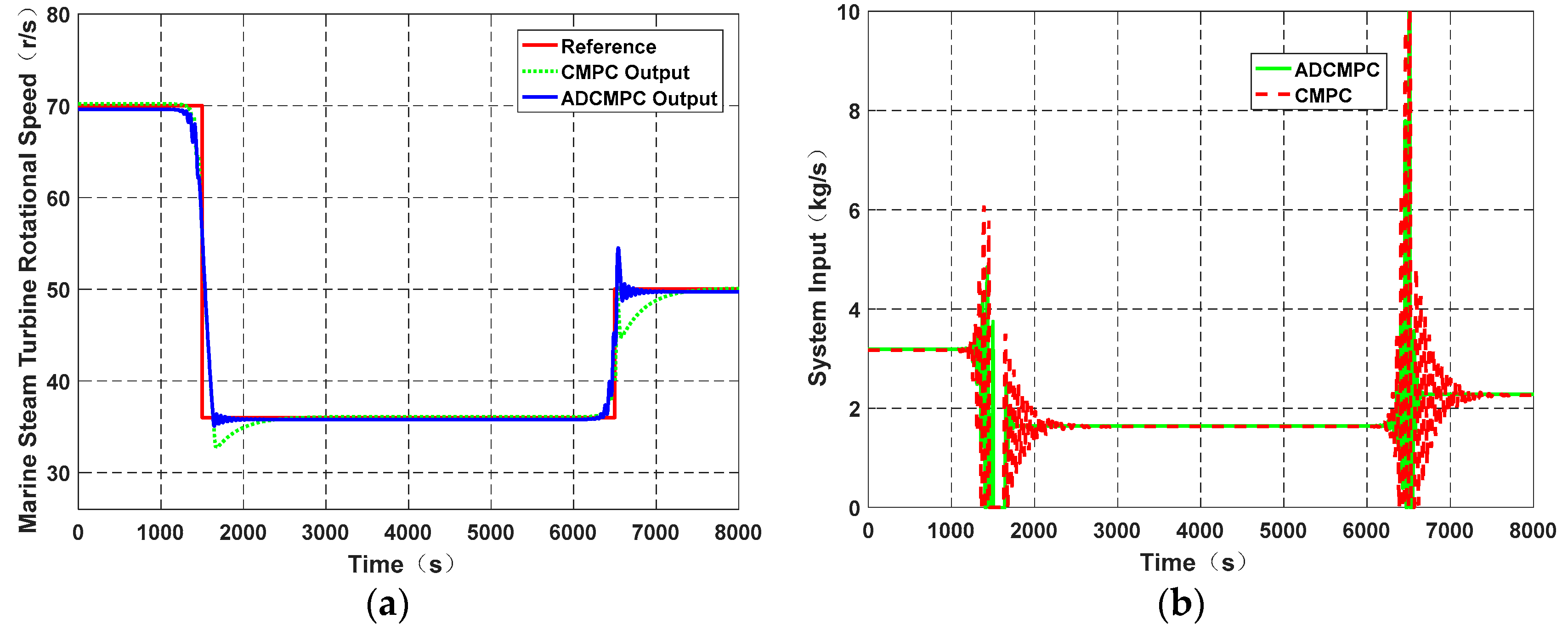
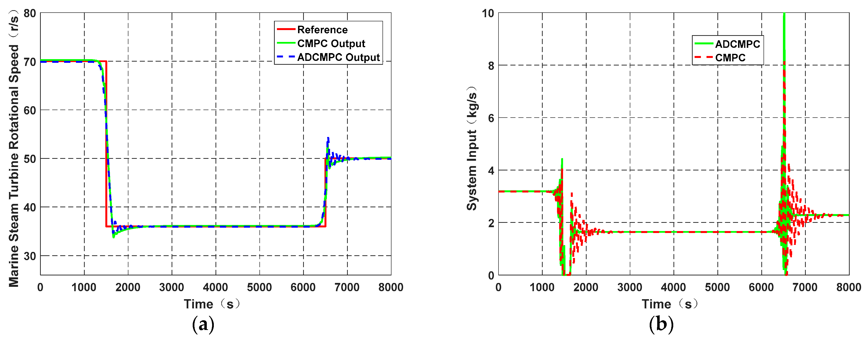
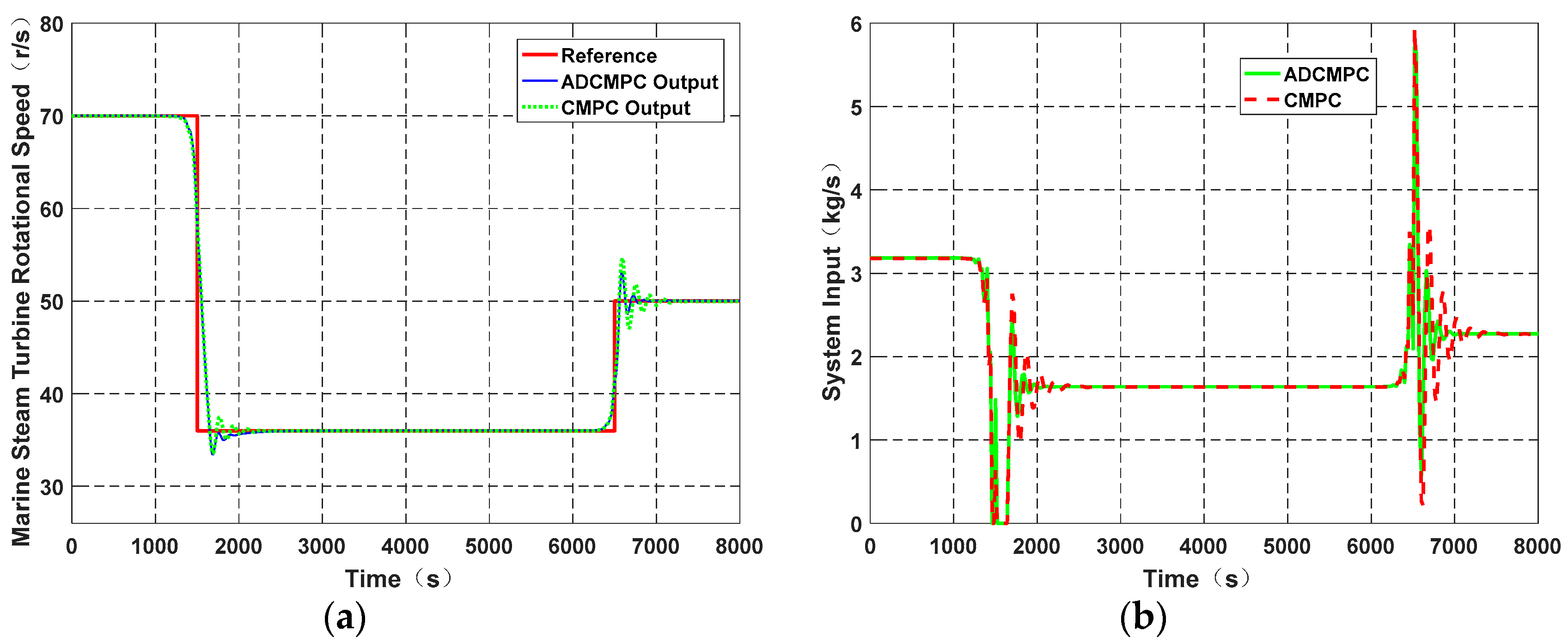
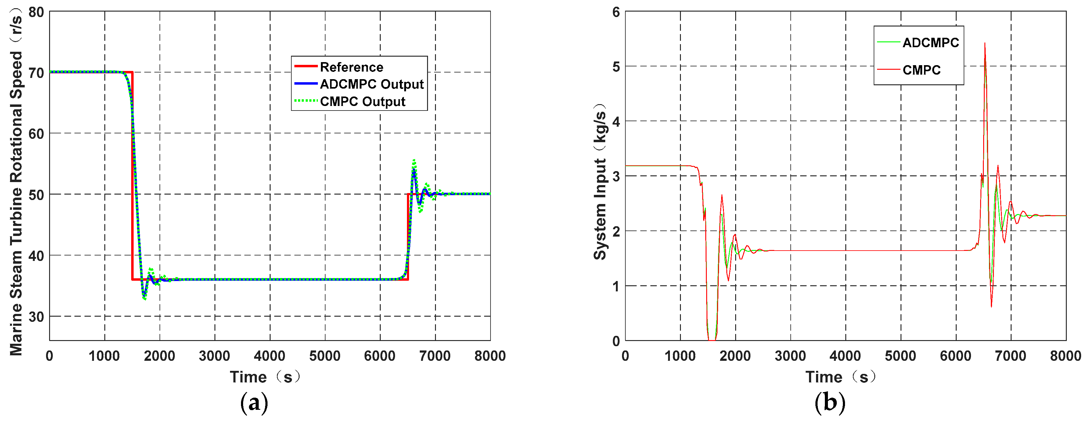
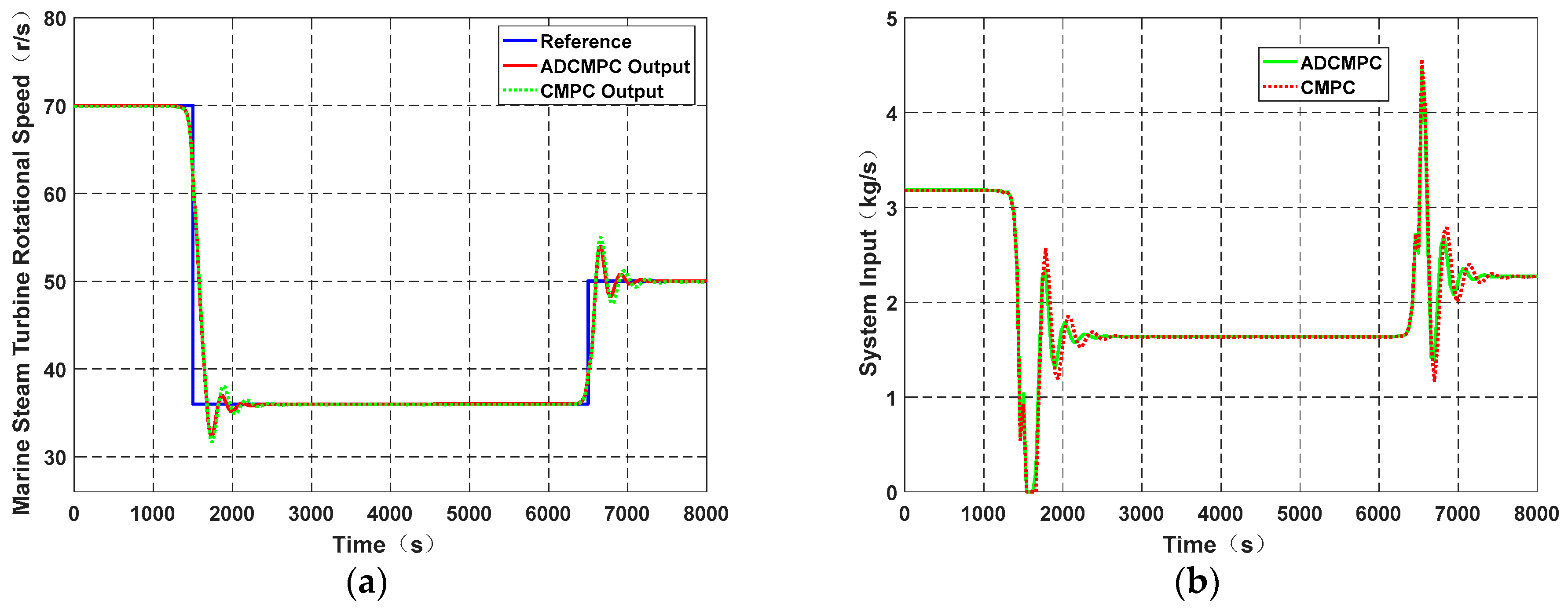
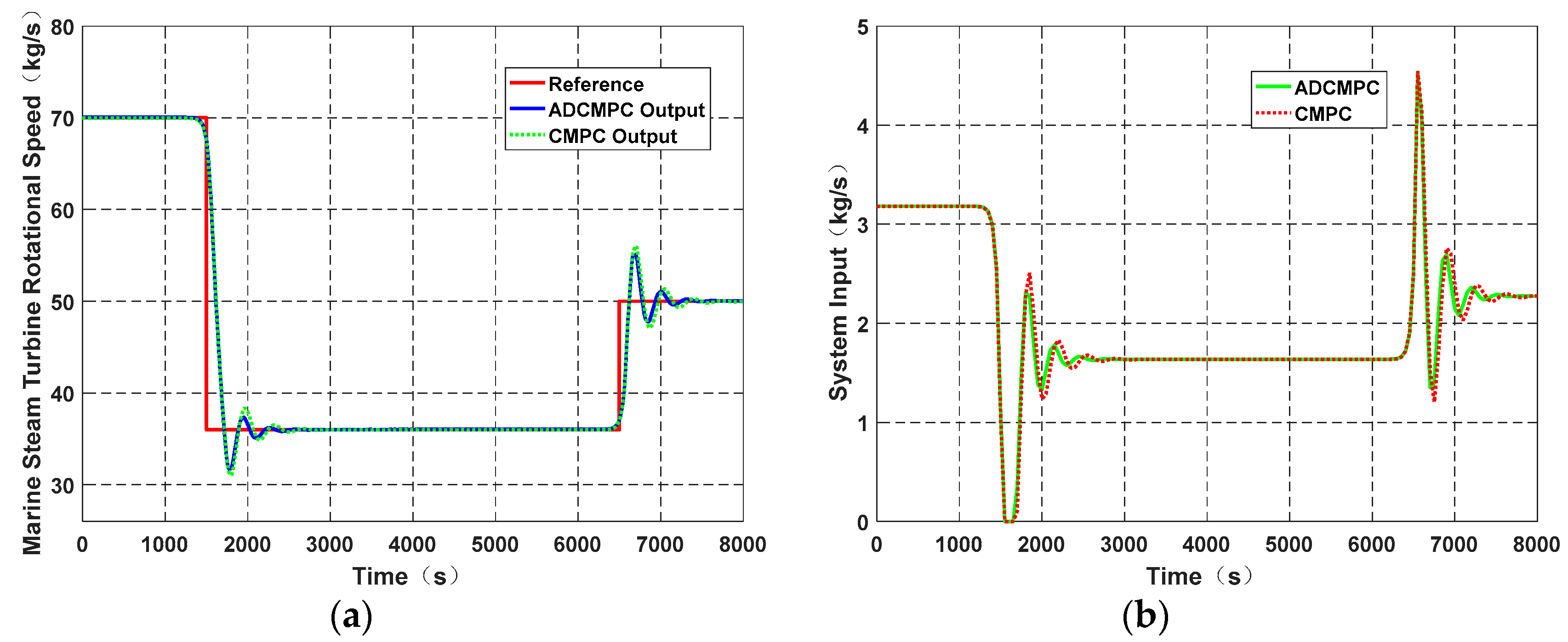
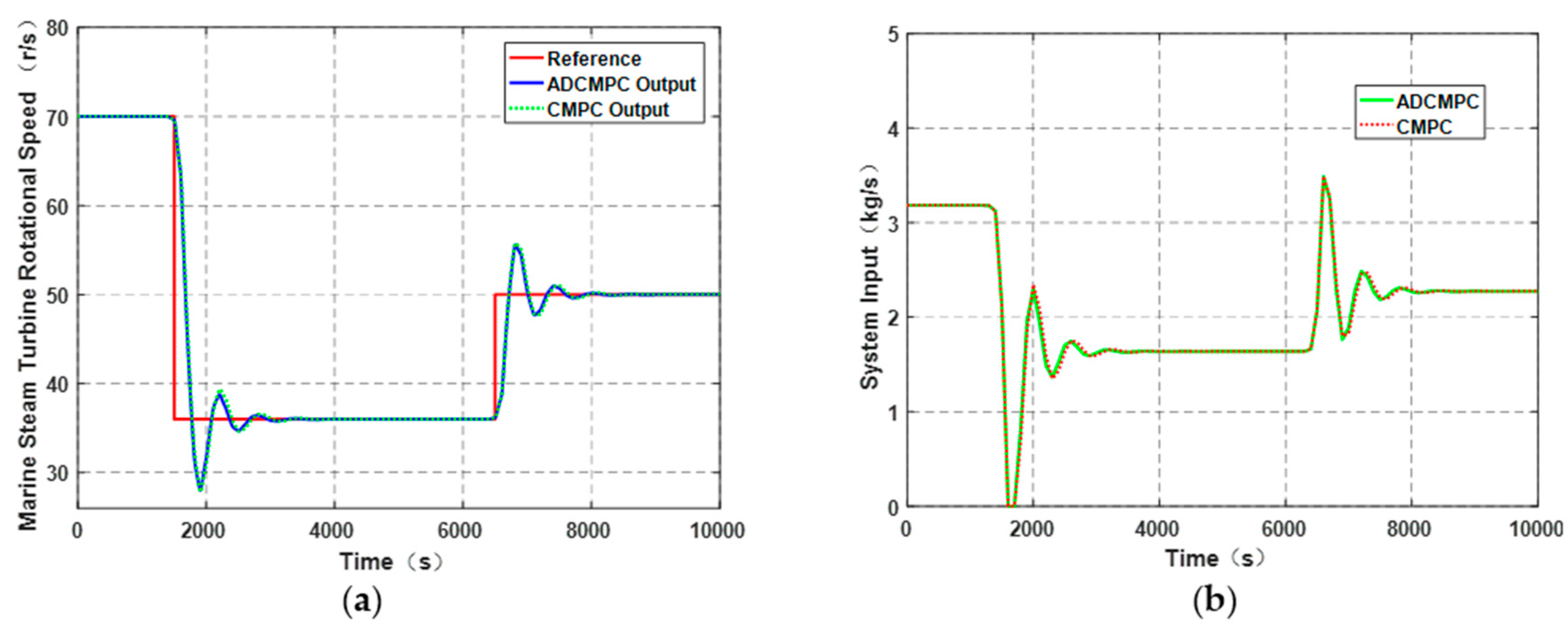
The simulation duration is 8000 s. Regarding the reference trajectory setting, the expected value of the marine turbine speed in the first 1500 s of the simulation is 70 r/s; then, the expected value in 5000 s is 36 r/s. Finally, the desired speed is 50 r/s. The sampling period is selected as 5 s, 10 s, 20 s, 30 s, 40 s, 50 s, 100 s; the rotational speed and control signal are compared in the following figures.
From Figure 7, Figure 8, Figure 9, Figure 10, Figure 11, Figure 12 and Figure 13, the following conclusions can be drawn:
1. From the perspective of dynamic characteristics, when the sampling period is small (Figure 7, Figure 8, Figure 9, Figure 10 and Figure 11), the ADCMPC algorithm can quickly converge to the expected rotational speed of marine steam turbines. Compared with CMPC, the ADCMPC indeed has better dynamic characteristics.
2. With the increase of sampling period, the gap between ADCMPC and the CMPC algorithms decreases. This is because as the sampling period increases, the difference between the actuator output u(t) and the control signal v(t) decreases. The specific performance of the simulation results is that the dynamic characteristics of the two control algorithms are not much different, and the control signal values are also very close. Especially when the sampling period reaches Ts = 100 s, the ADCMPC algorithm and CMPC algorithm are almost the same in terms of their rotational speed and control signal.
3. When the sampling period of the system becomes larger, the settling time of MSTRSCS increases gradually. This proves that the longer the sampling period, the longer the response time of the system and the longer the stability time of the system, and the worse the dynamic characteristics of the system.
4. The system sampling period cannot be taken as too small; when the sampling period Ts is less than 5 s, not only the ADCMPC algorithm but also the CMPC algorithm cannot achieve control performance, as some parameters in the model will be too small to calculate.
Generally speaking, the ADCMPC algorithm proposed in this paper is correct. The dynamic response characteristics of the system are improved, as well as achieving better steady-state characteristics, which prove its excellent engineering value.

4. Conclusions

This paper studies the rotational speed control problem of the marine steam turbine. To solve this problem, a novel ADCMPC algorithm is proposed which solves the shortcomings of the CMPC algorithm. A time-discrete mathematical model with actuator dynamic compensation is established to improve the accuracy of MSTRSCS. According to the novel time-discrete mathematical model, the difference between the control action u(t) and the control signal v(t) can be calculated accurately, so that the marine steam turbine can rapidly reach the desired rotational speed and reduce the amount of overshoot. The simulation results show that the ADCMPC algorithm is efficient and feasible. The ADCMPC algorithm reduces the dynamic response time of MSTRSCS and greatly improves the dynamic characteristics of the system. Future work should include increasing the complexity of the MSTRSCS mathematical model, making it closer to the real marine steam turbine; investigating the relevant parameters of the ADCMPC algorithm, such as the prediction horizon, the control horizon, output tracking error weighting and control input weighting, improving its optimization space. There is a coupling effect between the marine steam turbine rotational speed control loop and the marine boiler’s main steam pressure control loop [1]. The main steam pressure of the marine boiler is time-varying. The discrete-time model ignores the coupling effect of the rotational speed loop caused by the dynamic change of the main steam pressure loop during a sampling period. If the sampling period is relatively large, the coupling effect will be large and cannot be ignored. Therefore, future work will focus on the dynamic compensation predictive control of the marine steam turbine rotational speed control based on a time-continuous model. The study will be conducted based on the ideas of Gawthrop [46,47,48] and Mehdi Hosseinzadeh and Emanuele Garone [49,50,51].

Author Contributions

Conceptualization and supervision S.L. and B.Z.; methodology, L.W.; software, B.Z.; writing—original draft preparation, B.Z.; writing—review and editing, B.Z.; funding acquisition, S.L.

Funding

This research was funded by National Natural Science Foundation of China, grant number 51579047.

Conflicts of Interest

The authors declare no conflict of interest.

Nomenclature

TsSampling period
VThe ship navigation speed
FpropiThrust of the ith propeller
tdThe dimensionless thrust deduction coefficient
FdragThe backward drafting force of a ship when it is sailing
mThe quality of the ship
maThe dimensionless additional mass coefficient of the ship
Ek(t)The rotational kinetic energy of MSTRSCS
PT(t)The steam expansion work power in the marine steam turbine
PP(t)The load power of the propeller
JThe whole rotary inertia of MSTRSCS
KTThe total work done by the expansion of the unit mass steam in the marine steam turbine
nt(t)The rotational speed of MSTRSCS
u(t)The mass flow of the steam intake to the turbine
TPThe load torque of propeller
KQThe dimensionless torque coefficient
ρThe sea water density
DThe diameter of the propeller
κThe drag coefficient of propeller
nmaxThe maximum rotational speed
ΔκSymbol of KQ(nmaxnt(t))
y(t)Symbol of n2t(t)
Y(s)Laplace transform of y(t)
U(s)Laplace transform of u(t)
v(t)The control signal generated by the controller
T0The time constant of the actuator
KSymbol of KT
NuThe control horizon
NyThe prediction horizon
QNy-dimensional positive definite diagonal matrix
RNu-dimensional positive definite diagonal matrix
JCost function of MPC

References

  1. Xia, G.; Tang, Z.; Wang, Y.; Ren, L. Decoupling Coordinated Control System Based on PID Neural Network for Marine Steam Power Plant. In Proceedings of the 2009 WRI World Congress on Computer Science and Information Engineering, Los Angeles, CA, USA, 31 March–2 April 2009; pp. 116–120. [Google Scholar]
  2. Salamati, S.A.; Taghirad, H.D.; Chaibakhsh, A. Robust control of a steam turbine power based on a precise nonlinear model. In Proceedings of the 5th Conference on Thermal Power Plants, Tehran, Iran, 10–11 June 2014. [Google Scholar]
  3. Zhang, Y.; Zhu, Q. Predictive function control based on the LS-SVM for marine steam turbine system. In Proceedings of the Sixth International Conference on Natural Computation, ICNC 2010, Yantai, China, 10–12 August 2010. [Google Scholar]
  4. Kochummen, S.A.; Jaffar, N.E.; Nasar, A. Model Reference Adaptive Controller designs of steam turbine speed based on MIT Rule. In Proceedings of the 2015 International Conference on Control Communication & Computing India (ICCC), Trivandrum, India, 19–21 November 2015; pp. 7–11. [Google Scholar]
  5. Wu, K.; Zhang, T.; Lv, J.; Xiang, W. Model Predictive Control for Nonlinear Boiler-Turbine System Based on Fuzzy Gain Scheduling. In Proceedings of the IEEE International Conference on Automation and Logistics, Qingdao, China, 1–3 September 2008; pp. 1115–1120. [Google Scholar]
  6. Sun, J.H.; Wang, W.; Yu, H.Y. Turbine speed control system based on a fuzzy-PID. J. Mar. Sci. Appl. 2008, 7, 268–272. [Google Scholar] [CrossRef]
  7. Zhu, Q.; Yu, Z.; Zhang, J. Design of Fuzzy Neural Network Controller for Marine Steam Turbine System. In Proceedings of the Fourth International Conference on Natural Computation, Jinan, China, 18–20 October 2008. [Google Scholar]
  8. Liu, H.; Li, S.; Chai, T. Intelligent decoupling control of power plant main steam pressure and power output. Int. J. Electr. Power Energy Syst. 2003, 25, 809–819. [Google Scholar] [CrossRef]
  9. Liu, X.; Guan, P.; Chan, C.W. Nonlinear multivariable power plant coordinate control by constrained predictive scheme. IEEE Trans. Control Syst. Technol. 2010, 18, 1116–1125. [Google Scholar] [CrossRef]
  10. Li, S.; Lui, H.; Cai, W.-J.; Soh, Y.-C.; Xie, L.-H. A new coordinated control strategy for boiler-turbine system of coal-fired power plant. IEEE Trans. Control Syst. Technol. 2005, 13, 943–954. [Google Scholar]
  11. Åström, K.J.; Bell, R.D. Drum-boiler dynamics. Automatica 2000, 36, 363–378. [Google Scholar] [CrossRef]
  12. Åström, K.J.; Eklund, K. A simple non-linear drum boiler model. Int. J. Control 1975, 22, 739–740. [Google Scholar] [CrossRef] [Green Version]
  13. Bell, R.D.; Åström, K.J. Dynamics models for boiler-turbine alternator units: Data logs and parameter estimation for a 160 MW unit. Dept. Autom. Control Lund Inst. Technol. Lund Sweden Tech. Rep. 1987, TFRT-3192, 1–137. [Google Scholar]
  14. Tristan, P. Ship Motion Control: Course Keeping and Roll Stabilisation Using Rudder and Fins; Springer Publishing Company, Incorporated: Berlin/Heidelberg, Germany, 2010. [Google Scholar]
  15. Fossen, T.I. Handbook of Marine Craft Hydrodynamics and Motion Control; Wiley: New York, NY, USA, 2011. [Google Scholar]
  16. Zhang, L.J.; Jia, H.M.; Qi, X. NNFFC-adaptive output feedback trajectory tracking control for a surface ship at high speed. Ocean Eng. 2011, 38, 1430–1438. [Google Scholar] [CrossRef]
  17. Camacho, E.F.; Bordons, C. Model Predictive Control; Springer: London, UK, 2004. [Google Scholar]
  18. Rechaler, J.; Richalet, J.; Rault, A.; Papon, J. Model Predictive Heuristic Control: Applications to Industrial processes. Automatica 1978, 14, 413–428. [Google Scholar]
  19. Rouhani, R.; Mehra, R.K. Model Algorithmic Control (MAC): Basic Theoretical properties. Automattica 1982, 18, 401–414. [Google Scholar] [CrossRef]
  20. Cutler, C.R.; Ramaker, B.L. Dnamic matrix control-a computer control algorithm. In Proceedings of the American Control Conference, San Francisco, CA, USA, 1 January 1980. [Google Scholar]
  21. Garcia, C.E.; Morari, M. Internal model control—A unifying review and some new results. IEC Process Des. Dev. 1982, 21, 308–323. [Google Scholar] [CrossRef]
  22. Kuntze, H.B.; Jacubasch, A.; Richalet, J.; Arber, C. On the Predictive Functional Control of an Elastic Industrial Robot. In Proceedings of the 25th IEEE Conference on Decision and Control, Athens, Greece, 10 December 1986; pp. 1877–1881. [Google Scholar]
  23. Clarke, D.W.; Monhtadl, C.; Tuffs, P.S. Generalize Predictive Control—Part Ⅰ. The Basic Algorithm. Automatica 1987, 23, 137–148. [Google Scholar] [CrossRef]
  24. Clarke, D.W.; Monhtadl, C.; Tuffs, P.S. Generalize Predictive Control—Part Ⅱ. Extensions and Interpretations. Automatica 1987, 23, 149–162. [Google Scholar] [CrossRef]
  25. Kwon, W.H.; Pearson, A.E. On feedback stabilization of time-varying discrete linear systems. IEEE Trans. Autom. Control 1978, 23, 479–481. [Google Scholar] [CrossRef] [Green Version]
  26. Scokaert, P.O.M.; Clarke, D.W. Stabilising properties of con-strained predictive control. IEE Proc. Control Theory Appl. 1994, 141, 295–304. [Google Scholar] [CrossRef]
  27. Clarke, D.W.; Scattolini, R. Constrained receding-horizon predictive control. IEE Proc. Control Theory Appl. 1991, 138, 347–354. [Google Scholar] [CrossRef]
  28. Keerthi, S.S.; Gilbert, E.G. Optimal infinite-horizon feedback laws for a general class of constrained discrete-time systems: Stability and moving-horizon approximations. J. Optim. Theory Appl. 1988, 57, 265–293. [Google Scholar] [CrossRef] [Green Version]
  29. Mayne, D.Q.; Michalska, H. Receding horizon control of nonlinear systems. IEEE Trans. Autom. Control 1990, 35, 814–824. [Google Scholar] [CrossRef]
  30. Michalska, H.; Mayne, D.Q. Robust receding horizon control of constrained nonlinear systems. IEEE Trans. Autom. Control 1993, 38, 1623–1633. [Google Scholar] [CrossRef]
  31. Limon, D.; Alamo, T.; Salas, F.; Camacho, E.F. On the stability of constrained MPC without terminal constraint. IEEE Trans. Autom. Control 2006, 51, 832–836. [Google Scholar] [CrossRef]
  32. Jadbabaie, A.; Hauser, J. On the stability of receding horizon control with a terminal cost. IEEE Trans. Autom. Control 2005, 50, 674–678. [Google Scholar] [CrossRef]
  33. Chmielewski, D.; Manousiouthakis, V. On constrained infinite-time linear quadratic optimal control. Syst. Control Lett. 1996, 29, 121–129. [Google Scholar] [CrossRef]
  34. De Nicolao, G.; Magni, L.; Scattolini, R. Stabilizing nonlinear receding horizon control via a nonquadratic penalty. In Proceedings of the IMACS Multiconference CESA, Lille, France, 1 January 1996; pp. 185–187. [Google Scholar]
  35. Gilbert, E.G.; Tan, K.T. Linear systems with state and control constraints: The theory and application of maximal output admissible sets. IEEE Trans. Autom. Control 1991, 36, 1008–1020. [Google Scholar] [CrossRef]
  36. Parisini, T.; Zoppoli, R. A receding horizon regulator for nonlinear systems and a neural approximation. Automatica 1995, 31, 1443–1451. [Google Scholar] [CrossRef]
  37. Sznaier, M.; Damborg, M.J. Suboptimal control of linear systems with state and control inequality constraints. In Proceeding of the 26th IEEE Conference on Decision and Control, Los Angeles, CA, USA, 9–11 December 1987; Volume 76, pp. 1–762. [Google Scholar]
  38. Scokaert, P.O.M.; Rawlings, J.B. Constrained linear quadratic regulation. IEEE Trans. Autom. Control 1998, 43, 1163–1169. [Google Scholar] [CrossRef]
  39. De Oliveira Kothare, L.K.; Morari, M. Contractive model predictive control for constrained nonlinear systems. IEEE Trans. Autom. Control 2000, 45, 1053–1071. [Google Scholar] [CrossRef]
  40. Mayne, D.Q.; Rawlings, J.B.; Rao, C.V.; Scokaert, F.O.M. Constrained model predictive control: Stability and optimality. Automaica 2000, 36, 789–814. [Google Scholar] [CrossRef]
  41. De Nicolao, G.; Magni, L.; Scottolini, R. Stabilizing receding-horizon control of nonlinear time-varying systems. IEEE Trans. Autom. Control 1998, 43, 1030–1036. [Google Scholar] [CrossRef]
  42. Magni, L.; De Nicolao, G.; Magnani, L.; Scattolini, R. A stabilizing model-based predictive control algorithm for nonlinear systems. Automatica 2001, 37, 1351–1362. [Google Scholar] [CrossRef]
  43. Lee, J.W.; Kwon, W.H.; Choe, J. On stability of constrained receding horizon control with finite terminal weighting matrix. Automatic 1998, 34, 1607–1612. [Google Scholar] [CrossRef]
  44. Lee, J.W. Exponential stability of constrained receding horizon control with terminal ellipsoid constraints. IEEE Trans. Autom. Control 2000, 45, 83–88. [Google Scholar]
  45. Zhang, R.D.; Li, P.; Xue, A.K.; Jiang, A.P.; Wang, S.Q. A simplified linear iterative predictive functional control approach for chamber pressure of industrial coke furnace. J. Process Control 2010, 20, 464–471. [Google Scholar] [CrossRef]
  46. Gawthrop, P.J. Linear predictive pole-placement control: Practical issues. In Proceedings of the 39th IEEE Conference on Decision and Control (Cat. No.00CH37187), Sydney, Australia, 12–15 December 2000; Volume 1, pp. 160–165. [Google Scholar]
  47. Gawthrop, P.J.; Ronco, E. Predictive pole-placement control with linear models. Automatica 2002, 38, 421–432. [Google Scholar] [CrossRef] [Green Version]
  48. Chen, W.H.; Gawthrop, P.J. Constrained predictive pole-placement control with linear models. Automatica 2006, 42, 613–618. [Google Scholar] [CrossRef] [Green Version]
  49. Nicotra, M.M.; Garone, E. The Explicit Reference Governor: A General Framework for the Closed-Form Control of Constrained Nonlinear Systems. IEEE Control Syst. Mag. 2018, 38, 89–107. [Google Scholar] [CrossRef]
  50. Hosseinzadeh, M.; Garone, E. An Explicit Reference Governor for the Intersection of Concave Constraints. IEEE Trans. Autom. Control. 2019, 1. [Google Scholar] [CrossRef]
  51. Hosseinzadeh, M.; Cotorruelo, A.; Limon, D.; Garone, E. Constrained Control of Linear Systems Subject to Combinations of Intersections and Unions of Concave Constraints. IEEE Control Syst. Lett. 2019, 3, 571–576. [Google Scholar] [CrossRef]
  52. Wang, L. Model Predictive Control System Design and Implementation Using MATLAB®; Springer-Verlag London Limited: London, UK, 2009. [Google Scholar]
  53. Rajan, R.; Muhammed Salih, P.; Anilkumar, N. Speed Controller design for Steam Turbine. Int. J. Adv. Res. Electr. Electron. Instrum. Eng. J. 2013, 2, 4400–4409. [Google Scholar]
  54. Carlton, J.S. Marine Propellers and Propulsion; Butterworth–Heinemann: Oxford, UK, 1994. [Google Scholar]
  55. Tupper, E.C.; Rawson, K.J. Basic Ship Theory, Combined Volume; Butterworth-Heinemann: Oxford, UK, 2001. [Google Scholar]
  56. Kashima, T.; Takata, J. An optimal control of marine propulsion system considering ship dynamics. In Proceedings of the International Conference on Control Applications, Glasgow, UK, 18–20 September 2002. [Google Scholar]
  57. Jiang, P.; Gao, L.; Dai, Y. A new non-linear model of steam turbine unit for dynamic analysis of power system. In Proceedings of the International Conference on Power System Technology, Hangzhou, China, 24–28 October 2010. [Google Scholar]
  58. Chaibakhsh, A.; Ghaffari, A. Steam turbine model. Simul. Model. Pract. Theory 2008, 16, 1145–1162. [Google Scholar] [CrossRef]
  59. Zhao, S.; Maxim, A.; Liu, S.; De Keyser, R.; Ionescu, C. Effect of Control Horizon in Model Predictive Control for Steam/Water Loop in Large-Scale Ships. Processes 2018, 6, 265. [Google Scholar] [CrossRef]
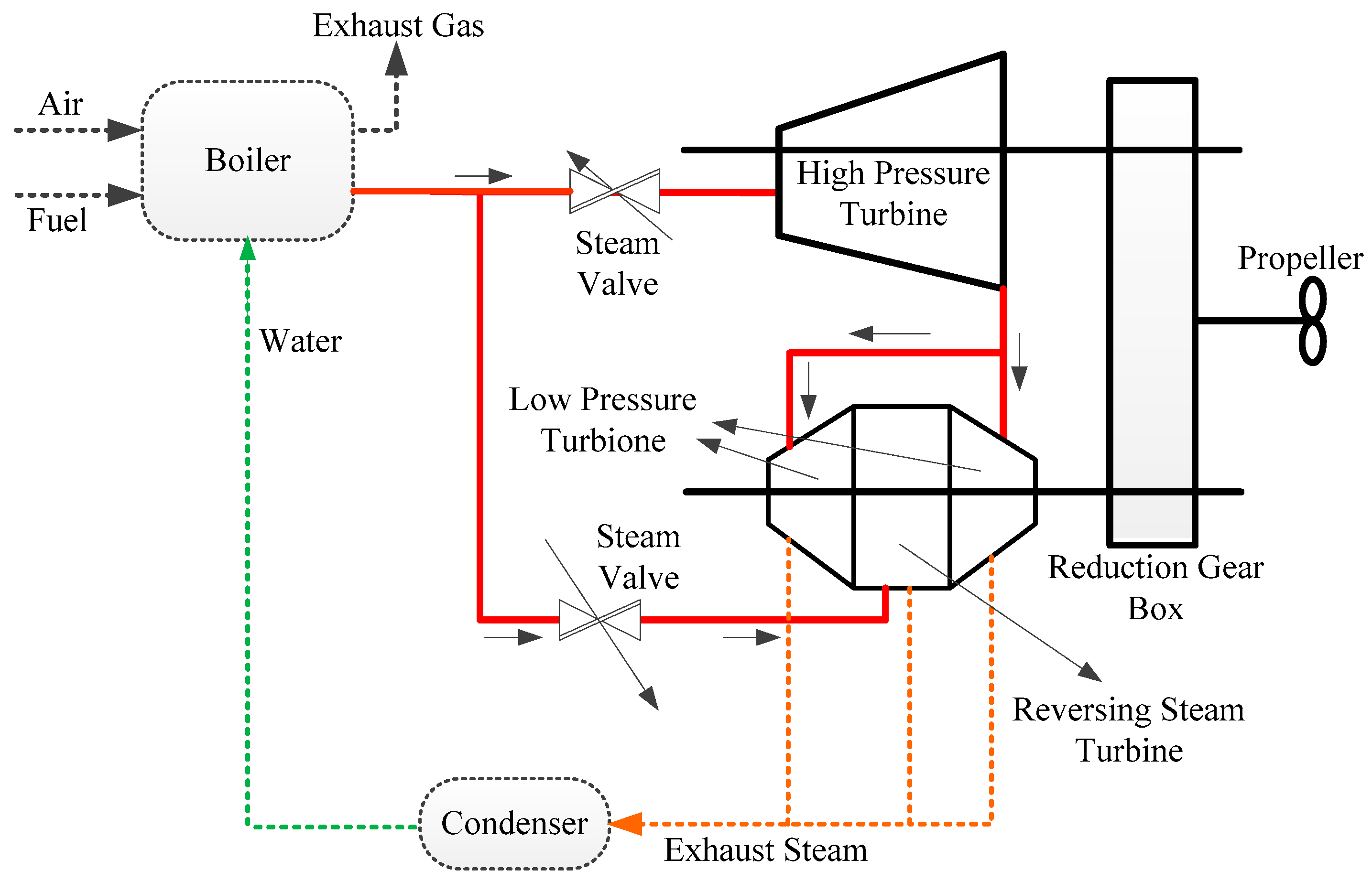
Figure 1. The marine steam turbine system.
Processes 07 00423 g001
Figure 2. The control signal in sampling periods.
Processes 07 00423 g002
Figure 3. The control structure of the MPC system.
Processes 07 00423 g003
Figure 4. The actuator response to step signal.
Processes 07 00423 g004
Figure 5. The actuator response to the control signal with the sampling period (a) Ts = 20 s, (b) Ts = 10 s, (c) Ts = 5 s, and (d) Ts = 3 s.
Processes 07 00423 g005
Figure 6. Difference between the actuator responses to the control signal.
Processes 07 00423 g006
Figure 7. Comparison of (a)-the rotational speed and (b)-control signal v(t) of the novel MPC with actuator dynamic compensation (ADCMPC) and conventional MPC (CMPC) with Ts = 5 s.
Processes 07 00423 g007
Figure 8. Comparison of (a)-the rotational speed and (b)-control signal v(t) of the ADCMPC and CMPC with Ts = 10 s.
Processes 07 00423 g008
Figure 9. Comparison of (a)-the rotational speed and (b)-control signal v(t) of the ADCMPC and CMPC with Ts = 20 s.
Processes 07 00423 g009
Figure 10. Comparison of (a)-the rotational speed and (b)-control signal v(t) of the ADCMPC and CMPC with Ts = 30 s.
Processes 07 00423 g010
Figure 11. Comparison of (a)-the rotational speed and (b)-control signal v(t) of the ADCMPC and CMPC with Ts = 40 s.
Processes 07 00423 g011
Figure 12. Comparison of (a)-the rotational speed and (b)-control signal v(t) of the ADCMPC and CMPC with Ts = 50 s.
Processes 07 00423 g012
Figure 13. Comparison of (a)-the rotational speed and (b)-control signal v(t) of the ADCMPC and CMPC with Ts = 100 s.
Processes 07 00423 g013
Table 1. Model parameters of the marine steam turbine.
SymbolValueSI-Unit
K22
T300s
T010s
τ120s