Article

Integrated Component Optimization and Energy Management for Plug-In Hybrid Electric Buses

School of Automobile, Chang’an University, Xi’an 710064, China
*
Author to whom correspondence should be addressed.
Processes 2019, 7(8), 477; https://doi.org/10.3390/pr7080477
Submission received: 30 May 2019 / Revised: 20 July 2019 / Accepted: 22 July 2019 / Published: 24 July 2019
(This article belongs to the Special Issue Energy, Economic and Environment for Industrial Production Processes)

Abstract

:
The complicated coupling of component design together with energy management has brought a significant challenge to the design, optimization, and control of plug-in hybrid electric buses (PHEBs). This paper proposes an integrated optimization methodology to ensure the optimum performance of a PHEB with a view toward designing and applications. First, a novel co-optimization method is proposed for redesigning the driveline parameters offline, which combines a nondominated sorting genetic algorithm-II (NSGA-II) with dynamic programming to eliminate the impact of the coupling between the component design and energy management. Within the new method, the driveline parameters are optimally designed based on a global optimal energy management strategy, and fuel consumption and acceleration time can be respectively reduced by 4.71% and 4.59%. Second, a model-free adaptive control (MFAC) method is employed to realize the online optimal control of energy management on the basis of Pontryagin’s minimum principle (PMP). Particularly, an MFAC controller is used to track the predesigned linear state-of-charge (SOC), and its control variable is regarded as the co-state of the PMP. The main finding is that the co-state generated by the MFAC controller gradually converges on the optimal one derived according to the prior known driving cycles. This implies that the MFAC controller can realize a real-time application of the PMP strategy without acquiring the optimal co-state by offline calculation. Finally, the verification results demonstrated that the proposed MFAC-based method is applicable to both the typical and unknown stochastic driving cycles, meanwhile, and can further improve fuel economy compared to a conventional proportional-integral-differential (PID) controller.

1. Introduction

In recent years, the deteriorating environmental problems and the shortage of fossil fuels have greatly promoted the development of plug-in hybrid electric vehicles (PHEVs). It is a promising solution to reduce the consumption of traditional energy and also to lessen environmental pollution, due to its multiple driven modes [1,2]. The co-optimization of driveline components and energy management strategy (EMS) can considerably enhance the fuel economy of PHEVs. It is usually considered as a complicated multiobjective and multiconstraint coupling optimization problem, thereby leading to a significant challenge to simultaneously optimize [3,4]. Additionally, optimization-based EMSes have been attested to be of tremendous potential for the fuel economy improvement of PHEVs. However, they still have serious technical drawbacks for real-time applications [5,6].
A co-optimization design of the driveline components and energy management control can be taken as a system-level optimization design problem. It comprises the optimization of the physical system and the control system [7]. Many researchers have dedicated much valuable work to improving the driveline efficiency and the fuel economy of multisource drive vehicles. Most of them have focused on a single-objective (or multiobjective) optimization problem of driveline matching, component sizing, topology design, or the EMS [8,9,10,11]. For the predefined single-shaft coaxial parallel plug-in hybrid electric bus (PHEB) in our research, component sizing and the energy management control are extremely significant to fuel economy. To guarantee the optimality of dynamic performance and fuel economy, the driveline design and the EMS should be simultaneously considered, as they are strongly coupled [12]. Previous work has disposed of the combined optimization problem in a bilevel manner, where the outer loop is for the former and the inner loop is for the latter [8,13]. Many optimization algorithms have also been extensively applied to solve this problem, such as a genetic algorithm (GA) [4,14], particle swarm optimization (PSO) [11,15], and simulated annealing (SA) [9,16]. Most of them have been utilized to optimally design the component parameters for an outer loop, while a rule-based EMS is nested in an inner loop. However, the optimization results were suboptimal and influenced by the established rules due to the coupling relationship between the component design and EMS [3,7]. To overcome this drawback, another category of methods integrating the evolutionary algorithm with dynamic programming (DP) was proposed to optimize component sizing and EMS simultaneously, and it has been certified to be of significance in improving fuel economy [6,15]. Nevertheless, it may not be suitable for dealing with multimodal optimization problems with many local minima. In addition, convex optimization has been confirmed to be one of the most acceptable methods for the simultaneous optimization design of the component parameters and energy management due to its receptivity of the global optimum and a higher computational efficiency [3,12,17,18]. However, it may have difficulty formulating an accurate convex model for a multiobjective optimization problem with a larger number of variables. Hence, a systematic optimization method to deal with the complicated coupling problem containing multiobjectives and multivariables is necessary.
The PHEV has been widely accepted by the markets due to its long electric mileage and energy-saving potential, both of which are affected by energy management [19]. Presently, energy management mainly concentrates on two categories: One is a rule-based strategy for practical application [20], and the other one is an optimization-based strategy for theoretical research. Since the latter has enormous potential to improve fuel economy, it has been extensively investigated by many researchers [21,22]. Among them, DP is the most acceptable method for global optimization with prior known driving conditions. However, it is not applicable for online applications, as future driving conditions are unknown. Therefore, it is usually deployed as a benchmark or is integrated with other methods to realize systematic optimization [23,24]. Moreover, many real-time control strategies have also been given more attention, such as adaptive Pontryagin’s minimum principle (A-PMP) [25], adaptive equivalent consumption minimization strategy (A-ECMS) [26], model predictive control (MPC) [27,28], stochastic dynamic programming (SDP) [29], and reinforcement learning-based real-time energy management [30]. Since the PMP can transform the global energy management problem into an instantaneous optimization problem by minimizing the Hamilton function, the PMP-based EMS has been one of the most promising methods for a real-time energy management application, where the determination of the co-state (or the equivalence factor) is one of the key issues [31,32,33].
Currently, various methodologies have been proposed to determine the optimal co-state (or the equivalence factor), aiming at implementing the PMP-based EMS online while decreasing fuel consumption. In Reference [34], the optimal co-state was considered as a constant value, under the assumption that battery characteristics are almost unchangeable with respect to the changing state-of-charge (SOC). To overcome this deficiency, the shooting method was employed in iterative computations to identify the optimal co-state trajectory. However, the acceptable initial co-state value should be provided in advance [31]. In Reference [35], an approach based on preformulated look-up tables was proposed to search for the optimal initial co-state value using the shooting method. Although these methods can make the PMP-based EMS applicable, it still requires plenty of driving information for a corresponding offline calculation. Hence, an adaptive control method was proposed in Reference [25], where the co-state was adaptively updated with variational driving conditions. Its main advantage is that the PMP-based EMS can be realized in real time, with minimal driving information needing to be known beforehand.
Considering the strong dependence of the co-state on future driving conditions, some prediction-based methods have also been presented to identify the co-state online, such as methodologies based on historical driving information and vehicle telemetry technology [36,37]. However, they still need to be further improved in terms of accuracy and reliability. Inspired by References [25] and [38], the identification of a co-state could be transformed into an SOC trajectory tracking problem, where the requirement for future driving information was dramatically decreased. When a predetermined linear reference SOC trajectory is known for a given bus route, a control parameter can be obtained as the co-state by adjusting the feedback SOC error with a proportional-integral-differential (PID) controller [6]. However, the predefined linear reference SOC trajectory has a distinct difference in contrast to the desired optimal SOC trajectory, and the actual co-state has a continuously large fluctuation around the optimal co-state trajectory. Therefore, a valid self-adaptive controller is essential to smooth the fluctuation quickly so as to approximately approach the optimal co-state trajectory during online driving. This will be of great significance to the online implementation of the PMP-based EMS.
Despite the availability of various optimization methods for driveline design and energy management control, there has been little research in consideration of the coupling between them. The optimized driveline based on a certain energy management control strategy (EMS) will not be optimal for another, especially when applying offline optimization results to online control. Therefore, the practicability and robustness of the optimization results need to be further considered. In practice, it is of great urgency to develop an integrated optimization methodology involving the design and application of PHEBs. Two contributions are added to supplement the previous literature. First, to eliminate the coupling between the component design and energy management during the PHEB optimization process, a nondominated sorting genetic algorithm-II (NSGA-II) and dynamic programming (DP) are combined, aiming at capturing the optimal driveline parameters based on a global optimal energy management strategy (EMS). The NSGA-II is employed to solve the multiobjective optimization problem, including fuel economy and acceleration time, while DP is utilized as the global optimal EMS. Second, an EMS based on Pontryagin’s minimum principle (PMP) is proposed to realize online optimal control of a PHEB, due to the inapplicability of DP to online optimization. Meanwhile, a novel model-free adaptive control (MFAC) method is employed to overcome the drawback that the co-state of the PMP needs to be optimized offline according to known driving cycles. The MFAC controller is designed to track the predefined linear state-of-charge (SOC) trajectory, and its control variable is treated as the co-state of the PMP. The proposed methodologies take advantage of the fact that the distance of the realistic bus route is known, and the SOC being predefined as linearity is reasonable and acceptable for unknown driving conditions.
The remainder of the paper is organized as follows. Section 2 introduces the framework of the integrated optimization process as well as a brief explanation for the formulation of the driving cycle. The detailed models of the studied PHEB are shown in Section 3. The co-optimization designs of the driveline component sizing and EMS are provided and discussed in Section 4. A real-time application of a PMP-based EMS employing a novel MFAC controller is proposed and verified in Section 5, followed by conclusions in Section 6.

2. Preparing for Integrated Optimization

To ensure the optimal performance of a PHEB in a real-time application, two key problems need to be solved (i.e., optimal component design and optimal real-time control). The first is to optimally design the driveline parameters whilst eliminating the impact of energy management, and the main objective is to simultaneously improve the dynamic and economic performance. The second is to realize the online application of optimization-based energy management, aiming at further decreasing fuel consumption. The two problems are integrated as one with a view toward vehicle design and application, and then the integrated optimization is conducted based on a real-world bus route.

2.1. Architecture of Integrated Optimization

A diagram illustrating the architecture of the integrated optimization process is shown in Figure 1. It contains the key technology and approaches for solving the integrated optimization design problem.
Overall, the integrated optimization is deployed as two layers containing both the offline and online optimizations. The offline layer captures the optimal driveline parameters, i.e., the speed ratios of the auto mechanical transmission (AMT) and final drive, through a co-optimization method that is a combination of a nondominated sorting genetic algorithm-II (NSGA-II) and a dynamic programming (DP) algorithm. Within co-optimization design, multiobjective optimization problems, including fuel consumption and acceleration time, are disposed by NSGA-II, while DP is employed as an energy management strategy (EMS). Since DP is the most acceptable global optimization method based on the Bellman principle [39,40], the impact of an EMS on the component design can be eliminated, and the driveline optimization solution is based on the optimal EMS. For the online layer, the optimization results of the offline layer are applied to the PHEB. The Pontryagin’s minimum principle (PMP) algorithm is employed as the instantaneous optimal EMS in the real-time application, due to its higher computational efficiency [41]. In particular, the co-state of the PMP is adjusted online by the model-free adaptive control (MFAC) method in accordance with the predefined linear reference state-of-charge (SOC), in which no driving cycle is required to calculate the optimal co-state offline.

2.2. Synthesis of the Representative Driving Cycle

The optimization results of the driveline and EMS are susceptible to driving conditions [42]. Therefore, a representative driving cycle needs to be synthesized to reflect real-road driving conditions for the purpose of optimizing the PHEB. As shown in Figure 2, abundant historical driving data were collected via the onboard measurement method from a real-world bus route. The trip distance from the starting station to the final station was approximately 20.5 km, and each measurement data point was obtained from both a global positioning system (GPS) and Virtualbox (VBOX). More than 285,652 velocity data points were collected for the synthesis of the driving cycle, traveling for approximately 1435 km.
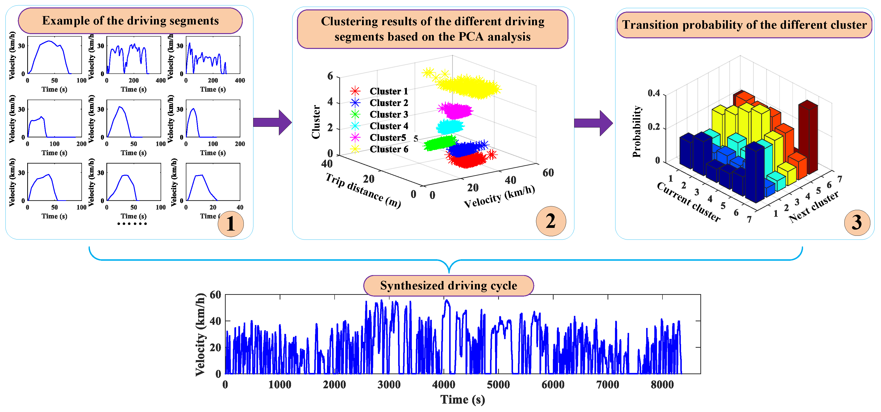
The driving segment is partitioned by a microtrip method from the historical driving data, and a principal component analysis (PCA) together with a k-means clustering method is employed to synthesize a driving cycle [43]. As shown in Figure 3, the main process of the driving cycle synthesis can be summarized as three steps. First, the measured driving data are divided into some driving segments, where the starting and the ending velocities for each segment need to be zero. Second, the statistical properties of each segment are analyzed with the PCA method to decrease the dimensionality of the selected characteristic parameters, and the driving segments that have similar properties are clustered into the same category by the k-means clustering method. Finally, the transition probability between two clusters is calculated according to the clustering results, and the driving segments belonging to the different clusters are randomly chosen to generate a candidate driving cycle through Monte Carlo methodology [44]. Then, the most acceptable driving cycle reflecting the real-road conditions is selected according to the comparison results of the statistical properties between the candidates and measured data. Moreover, the road slope is neglected in the synthesis process of the driving cycle, due to the road slope of the researched bus route being within ±0.01°. The detailed process of synthesizing a typical driving cycle with the PCA and k-means clustering method can be found in Reference [43].

3. PHEB Models

3.1. Configuration and Parameters

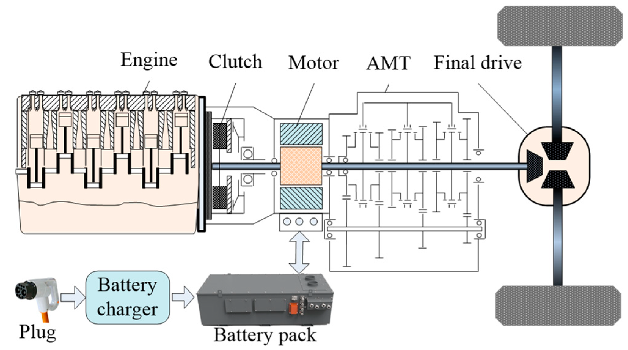
As shown in Figure 4, a PHEB with single-shaft parallel configuration was investigated. The driveline is mainly composed of a diesel engine, electric motor, auto mechanical transmission (AMT), final drive, and power battery pack. The main parameters are given in Table 1.

3.2. Engine Model

The engine model is simplified as a steady-state fuel consumption model neglecting the impact of temperature and dynamic performance. The fuel consumption per unit time of the diesel engine can be calculated by the following equation:
{ L f u e l = P e b e ( T e , ω e ) 367.1 ρ g P e = T e ω e ,
where Lfuel denotes the fuel consumption per unit time, Pe denotes the output power of the engine, Te and ωe respectively denote the torque and the rotational speed of the engine, be (Te, ωe) is the fuel consumption rate (which can be derived through the interpolation method from a brake-specific fuel consumption (BSFC) map (as shown in Figure 5)), ρ is the density of diesel oil, and g is the gravitational acceleration.

3.3. Motor Model

The motor adopted in the researched PHEB driveline can work as a traction motor or generator in the driving or generating mode. Therefore, the motor power consumption can be described as
{ P m = T m ω m η m s g n ( T m ) s g n ( T m ) = { 1 1 T m 0 T m < 0 d r i v i n g m o d e g e n e r a t i n g m o d e ,
where Pm is the output power of the motor; Tm and ωm denote the motor torque and the motor rotational speed, respectively; and ηm is the efficiency of the motor, which can be interpolated by the motor efficiency map (Figure 6).
Moreover, according to the configuration of the studied PHEB, the rotational speed of the wheel will be governed by the engine and motor, as well as the AMT and final drive. The relationship between them is described as [24]
ω w = ω e i A M T i f = ω m i A M T i f ,
where ωw is the rotational speed of the wheel, and iAMT and if are the speed ratio of the AMT and final drive, respectively.

3.4. Battery Model

A lithium-ion battery is equipped on the PHEB for its higher stability and longer operating distance. The battery model is simplified as an internal resistance battery model where the basic physical model can be derived from a static equivalent circuit, as shown in Figure 7 [6]. The battery load power can be expressed as Equation (4) when ignoring the thermal temperature effects and transients of the battery:
P b a t = V o c I b a t I b a t 2 R b a t ,
where Pbat denotes the battery load power, Ibat denotes the battery current, and Voc and Rbat denote the open-circuit voltage and the internal resistance of the battery, respectively.
As shown in Figure 8, Voc and Rbat are usually described as a function of the SOC, and the relationship between them can be acquired from a battery performance bench test. According to Equation (4), battery system dynamics are expressed as [20,31]
d S O C d t = V o c V o c 2 4 R b a t P b a t 2 R b a t Q b a t ,
where Qbat denotes the nominal capacity of the battery. In addition, Equation (5) can be transformed into a discrete form [20].
S O C k + 1 = SOC k V o c _ k + 1 V o c _ k + 1 2 4 R b a t _ k + 1 P b a t _ k + 1 2 R b a t _ k + 1 Q b a t

3.5. Vehicle Longitudinal Dynamics

Longitudinal dynamics have great influence on the performance of an automobile. When ignoring other dynamic models, the PHEB is considered to be a point mass model. The power requirement of the automobile can be derived from Equation (7):
P r e q = ( P e + P m ) / η T ( M r g f r cos α + M r g sin α + 1 2 C d A ρ d u a 2 + δ M r d u a d t ) u a 3600 η T
where Mr is the gross mass of the automobile, g is the acceleration of gravity, fr is the rolling resistance coefficient, α is the road slope, Cd is the aerodynamic drag coefficient, A is the windward area, ρd is the air density, ua is the velocity of the automobile, δ is the correction coefficient of the rotation mass, and ηT is the efficiency of the driveline.

4. Co-Optimization Framework

To solve the complicated coupled optimization problem between the driveline components and energy management, a co-optimization framework was established for the PHEB based on a synthesized real-road driving cycle. As shown in Figure 9, the co-optimization framework contains two modules, a driveline parameters optimization module and an energy management optimization module. The former is for finding the preferable speed ratios of the driveline considering the economic and dynamic performance comprehensively, while the latter is for designing a global optimal EMS corresponding to the speed ratios provided by the former. As NSGA-II has the advantage of fast convergence toward the optimal Pareto front while guaranteeing the diversity of a solution [45], it was employed to deal with the multiobjective optimization problems of the driveline, while DP algorithm was used to avoid the impact of the EMS on the optimality.
During the co-optimization process, the speed ratios of the driveline are optimized based on the fast nondominant sorting algorithm and elitism of the NSGA-II. Then, the optimal power distribution together with the minimum fuel consumption is calculated through DP, returning to the driveline parameters optimization module. Finally, the most acceptable speed ratios are determined according to the minimum evaluation index. Therefore, the optimization results have higher fitness with the optimal EMS, benefitting the optimization design of the online EMS.

4.1. Problem Formulation

To comprehensively improve the performance of the PHEB, fuel consumption and dynamic performance are simultaneously considered as the overall optimization objectives, and the dynamic performance is also treated as a constraint, for which the acceleration time of 0–50 km/h in the motor drive mode needs to be less than 20 s. In addition, some physical constrictions also need to be considered to guarantee the reasonability of the optimization results. The optimization model can be described as
{ f ( x ) = min [ f u e l ( x ) ; A c c _ t i m e ( x ) ] ; x = [ g e a r ( i ) ; i = 1 , 2 , 3 , 4 f i n a l _ d r i v e ] S . t . { A c c _ t i m e ( x ) 20 < 0 g e a r ( i ) l o w < g e a r ( i ) < g e a r ( i ) h i g h f i n a l _ d r i v e l o w < f i n a l _ d r i v e < f i n a l _ d r i v e h i g h
where fuel(x) denotes the fuel consumption function; Acc_time(x) denotes the acceleration time from 0 to 50 km/h for the PHEB (when the road slope is ignored); gear(i) denotes the designed speed ratios of the AMT, whose lower and higher boundaries are restricted by gear(i)low and gear(i)high, respectively; and final_drive denotes the designed speed ratio of the final drive, with its lower and upper limits being final_drivelow and final_drivehigh, respectively.
The speed ratios optimized by the driveline optimization module are synchronously applied to EMS optimization at each iteration. Then, the control strategy, including the power distribution and gear shifting, is redesigned through the DP algorithm. Meanwhile, the corresponding fuel consumption is calculated and provided to the NSGA-II. The system state space equation of the DP-based EMS is expressed as
{ x ( k + 1 ) = f [ x ( k ) , u ( k ) ] , k = 0 , 1 , , N 1 x ( k ) = [ S O C ( k ) , g x ( k ) ] u ( k ) = [ t h r o t ( k ) , s h i f t ( k ) ] ,
where f denotes the state function of the discrete system; x(k) is the state vector (i.e., the optimization variables of the DP), where SOC(k) and gx(k) represent the state vector of the battery and AMT, respectively; and u(k) denotes the control vector, for which throt(k) and shift(k) represent the control vector of the engine (throttle percentage) and the AMT (gear shifting command), respectively. Furthermore, the control vector of the AMT is defined as −1, 0, and 1 to represent downshift, hold, and upshift, respectively. In combination with Equation (6), the state vector can be rewritten as the following equation when the sampling time for the control problem is designed as 1 s:
{ S O C ( k + 1 ) = S O C ( k ) V o c ( k ) V o c 2 ( k ) 4 R b a t ( k ) P b a t ( k ) 2 R b a t ( k ) Q b a t ( k ) g x ( k + 1 ) = { 1 g x ( k ) + s h i f t ( k ) < 1 4 g x ( k ) + s h i f t ( k ) > 4 g x ( k ) + s h i f t ( k ) o t h e r w i s e .
Moreover, the objective of the DP-based EMS is to find the optimal control input u(k) to minimize the cost function, which can be described as
J = k = 0 N 1 L ( x ( k ) , u ( k ) ) = k = 0 N 1 [ L f u e l ( k ) + β | s h i f t ( k ) | ] ,
where N is the duration of the driving cycle, and L denotes the instantaneous cost at the k-th step. The cost function J is composed of the fuel consumption Lfuel(k) and the penalty of the gear shifting operation β|shift(k)|, where the weight factor β can coordinate the contradiction between fuel consumption and frequent gear shifting when given a suitable value. Moreover, the optimization problem should also be restricted by
S . t . { ω e _ m i n ( k ) ω e ( k ) ω e _ max ( k ) ω m _ m i n ( k ) ω m ( k ) ω m _ max ( k ) P e _ m i n ( ω e ( k ) ) P e ( k ) P e _ max ( ω e ( k ) ) P m _ m i n ( ω m ( k ) ) P m ( k ) P m _ max ( ω m ( k ) ) 0.35 S O C f 0.4 ,
where ωe(k) and ωm(k) denote the rotational speed of the engine and the motor at the kth step, whose lower and higher boundaries are respectively limited by ωe_min(k), ωe_max(k), ωm_min(k), and ωm_max(k); Pe(k) and Pm(k) denote the output power of the engine and the motor at the kth step, where the lower and higher boundaries are restricted by Pe_min(k), Pe_max(k), Pm_min(k), and Pm_max(k) respectively; and SOCf is the terminal desired SOC of the battery, whose constraint is designed as a scope from 0.35 to 0.4.

4.2. Boundaries

To analyze the impact of the driveline parameters on vehicle performance, a design of experiment (DOE) methodology was employed while using the optimal Latin hypercube (OLH) algorithm to randomly generate 500 samples in a five-dimensional vector space [46], where each row vector can represent a combination of the speed ratios of the AMT and final drive. The responses of fuel consumption and acceleration time with respect to the speed ratios are respectively shown in Figure 10 and Figure 11. It can be seen that gear 4 had the most positive influence on both fuel consumption and acceleration time, while other factors also inordinately impacted vehicle performance. Gear 1 had an insignificant influence on fuel economy, while it had an advantage in improving acceleration performance, and gear 2 was just to the contrary. Moreover, the increase of the speed ratios for the final drive and gear 3 had a negative impact on fuel economy, but was beneficial to the improvement of dynamic performance. The analysis results from our research indicated that all five variables need to be optimized, and the boundaries of the optimization variables need to be well-designed in order to obtain suitable optimal parameters.
As shown in Table 2, to avoid the shock of gear shifting, the limits of the speed ratios for the AMT were predefined by restricting the adjacent gear speed ratio within a scope from 1.4 to 1.8. In addition, the boundary of the final drive speed ratio was designed within 5.5 to 6.5 according to the existing products.

4.3. Optimization Results Analysis

For a multiobjective optimization problem, the objectives usually conflict with each other. Inspired by Reference [46], we established an evaluation index, including fuel consumption and acceleration time, to determine the best driveline parameters with respect to the comprehensive performance of the PHEB, which is governed by
E _ i n d e x = w 1 s 1 f u e l ( x ) + w 2 s 2 A cc _ t i m e ( x ) ,
where E_index represents the evaluation index; w1 and w2 denote the weight factors of the two objectives, and the sum of w1 and w2 must be 1; and s1 and s2 denote the scale factors utilized to balance the order of magnitude between different performance requirements.
In this paper, the order of magnitude for the two objectives is consistent, and herein, the scale factors s1 and s2 are prescribed as 1. Meanwhile, the weight factors w1 and w2 are defined as 0.5 to give a further explanation for the solution of the co-optimization problem. Moreover, to analyze the influence of weight factors on the optimization results, 11 solutions were obtained with diverse weight factors w1 varying from 0 to 1. The initial parameter settings of the NSGA-II solution are shown in Table 3, and the main steps and a detailed explanation can be found in References [47,48].
The Pareto front of the co-optimization problem is shown in Figure 12, where there are multiple sets of solutions in a feasible region, and the best-found point can be obtained according to the minimum evaluation index based on the given weight factors between two objectives. Moreover, some solutions in the infeasible region also exist due to the constraint of acceleration time.
The optimization process is shown in Figure 13, where the maximum iterations endured for 1000 generations. It could be found that the speed ratios and the evaluation index gradually converged with increments of the iteration steps, and both became stable after 600 iteration steps. The optimal speed ratio could be obtained and corresponded to the best-found point with a minimum evaluation index, at the 854th iteration step [46,47].
As shown in Figure 14a, the optimal speed ratios change with the weight factor w1 which is varying from 0 to 1, and the variations in the different variables have distinguished characteristics. Gear 1, gear 4, and the final drive have tiny changes in the variation of the weight factor, while gear 2 and gear 3 are fairly distinguishing. Without the consideration of the case that w1 is 0 or 1, the speed ratio of the gear 2 descends with an increase in w1, while gear 3 ascends gradually. In addition, the variation in the optimization objectives corresponding to the changing of the weight factor is shown in Figure 14b. With an increase in the weight factor w1, the fuel consumption decreases from 11.784 L/100 km to 11.755 L/100 km, and the acceleration time increases from 18.827 s to 18.874 s. This indicates that the variation in the weight factor does have an impact on the optimization results. Moreover, there is an incompatibility between the two objectives. To achieve a compromise, the best driveline parameters are determined corresponding to the minimum evaluation index when the weight factor w1 is chosen as 0.5, and the optimization result is shown in Table 4.
The fuel economy and acceleration performance of the best-found design point were respectively improved by 4.71% and 4.59%, compared to the current driveline. Therefore, the proposed co-optimization method has a remarkable advantage for the improvement of dynamic and economic performance. More importantly, the driveline parameters are obtained on the basis of the optimal EMS, which is of great significance in adopting them into a real-time application of energy management optimization.
In addition, the economic gear shifting schedule can be designed based on the co-optimization results of the best-found point so as to be utilized as a real-time strategy for the AMT control. As shown in Figure 15, the circles with various colors indicate the optimal AMT gear position, which is required for the economic working points of the engine. Hence, it can roughly pick up the economic gear shifting schedule between the adjacent gears. To avoid frequent gear shifting, a gear shifting delay was also designed, where the solid line and the dotted line represent upshift and downshift, respectively.

5. Real-Time Application of the Energy Management Strategy

Currently, Pontryagin’s minimum principle (PMP) has been widely adopted for the energy management of PHEBs [25,49]. However, it is still a great challenge to apply the PMP to the EMS in real time for unknown driving cycles. Inspired by previous literature, we transformed this challenge into an SOC trajectory tracking problem in our research [6,25]. Meanwhile, a novel controller based on a model-free adaptive control (MFAC) was employed to adjust the co-state of the PMP online to realize a real-time application. The scheme for our proposed PMP-based real-time energy management is shown in Figure 16.

5.1. PMP Problem Formulation

When energy management is treated as a constrained optimization problem for a given driving cycle, PMP can be utilized to achieve real-time energy management control. Assuming the battery is exhausted exactly at the end of a round trip for the given bus route, the optimization objective of the PMP-based EMS can be dominated just by fuel consumption, and the objective function is expressed as
J = min t 0 t f L fuel ( u ( t ) ) d t ,
where Lfuel can be obtained by Equation (1); u(t) is the control input of the PMP, which denotes the throttle opening of the engine; and [t0, tf] is the optimization horizon. During the application of the PMP, the optimal solution is usually solved by the Hamilton function, H, which can be presented as
H ( S O C ( t ) , u ( t ) , λ ( t ) ) = L f u e l ( u ( t ) ) + λ ( t ) S O ˙ C ( t ) ,
where λ(t) denotes the co-state in PMP, and the S O C ˙ (t) is given by Equation (5). Furthermore, the PMP can transform the global problem into a local instantaneous problem by capturing the optimal control variable u*(t) at each instantaneous time to minimize the Hamilton function,
u * ( t ) = arg min H ( S O C ( t ) , u ( t ) , λ ( t ) ) ,
where λ(t) is regarded as the optimization variable, and the state together with the co-state dynamic equations can be expressed as [25]
{ S O ˙ C = H λ = f ( S O C ( t ) , P b a t ( t ) ) λ ˙ ( t ) = H S O C = λ f ( S O C ( t ) , P b a t ( t ) ) S O C .
Accordingly, two constrained boundaries are necessary for the sake of optimality, which are denoted as SOC(t0) and SOC(tf), representing the initial and terminal states of the SOC, respectively. Meanwhile, some physical limitations on the components are also needed to ensure the availability of the PMP, which are incorporated as
S . t . { ω e _ m i n ( t ) ω e ( t ) ω e _ max ( t ) ω m _ m i n ( t ) ω m ( t ) ω m _ max ( t ) P e _ m i n ( ω e ( t ) ) P e ( t ) P e _ max ( ω e ( t ) ) P m _ m i n ( ω m ( t ) ) P m ( t ) P m _ max ( ω m ( t ) ) .

5.2. Reference SOC

To decrease the fuel consumption of the engine, the battery energy is expected to be depleted to its minimum. Therefore, it is reasonable to treat the battery minimum SOC as the terminal value of the reference SOC at the end of the trip. Moreover, the historical driving data (in Section 2.2) indicated that the road slope can be neglected. Hence, the reference SOC is approximately treated as a linear function of the current driving distance [6,31], which can be described as
S O C ref = S O C 0 ( S O C 0 S O C f ) d t o t a l d ,
where SOCref is the linear reference SOC; SOC0 and SOCf are the initial and terminal SOC values, respectively; dtotal denotes the whole trip distance; and d represents the travel distance.

5.3. MFAC Controller Design

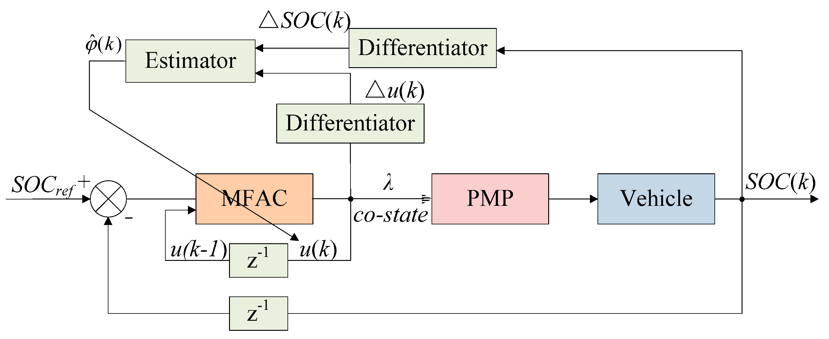
Despite the initial and terminal SOC being completely defined in the optimization problem, the optimal co-state λ(t) can only be calculated by an offline method. To apply the PMP-based EMS in real time without offline calculation, an MFAC controller was designed to adjust the co-state value λ online. As shown in Figure 17, the MFAC controller mainly consists of a control module and an estimating module, where the currently estimated variables with the control variables are calculated and updated in a discrete-time state [50,51].
The real-time adjustment of the co-state for PMP is treated as a discrete-time nonlinear problem, which can be successfully realized by the MFAC controller. The system is expressed by the following data model:
{ S O C ( k + 1 ) = S O C ( k ) + φ ( k ) Δ λ ( k ) Δ λ ( k ) = λ ( k ) λ ( k 1 ) Δ S O C ( k ) = S O C ( k ) S O C ( k 1 ) ,
where φ(k)∊R is the bounded pseudopartial derivative (PPD) of the system; and SOC(k) and λ(k) are the output variable and control variable of the system at time k, representing the current SOC and co-state, respectively.
For the control algorithm of the MFAC, the one-step-ahead prediction error cost function is used to eliminate excessive control efforts [50]. The control law is expressed as
λ ( k ) = λ ( k 1 ) + ρ k φ ( k ) λ k + | φ ^ ( k ) | 2 [ S O C * ( k + 1 ) S O C ( k ) ] ,
where ρk is the step factor, which is added to make the control algorithm more general; λk is the weighting factor that restricts the changing rate of the control input; SOC*(k + 1) denotes the value of reference SOC at the k + 1 step; and φ ^ (k) is the estimation value of φ(k), which is calculated by the following equation:
{ φ ^ ( k ) = φ ^ ( k 1 ) + η k Δ λ ( k 1 ) × [ Δ S O C ( k ) φ ^ ( k 1 ) Δ λ ( k 1 ) ] μ k + | Δ λ ( k 1 ) | 2 φ ^ ( k ) = φ ^ ( 1 ) if φ ^ ( k ) ε , o r | Δ λ ( k 1 ) | ε ,
where ηk denotes the step factor, μk denotes the weighting factor, ε denotes a small positive constant, and φ ^ (1) denotes the initial value of φ ^ (k).

5.4. Results and Discussion

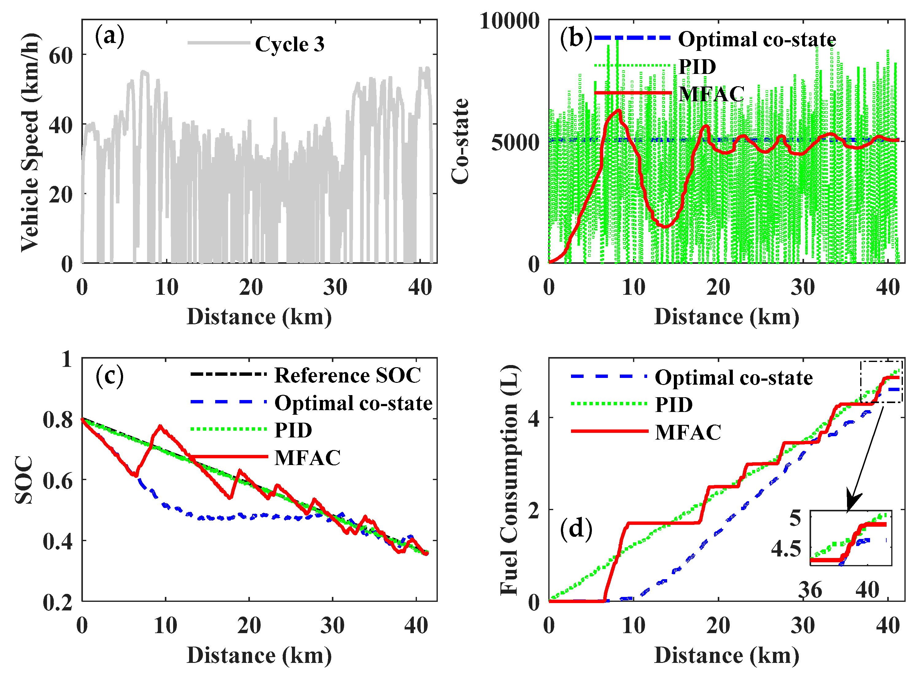
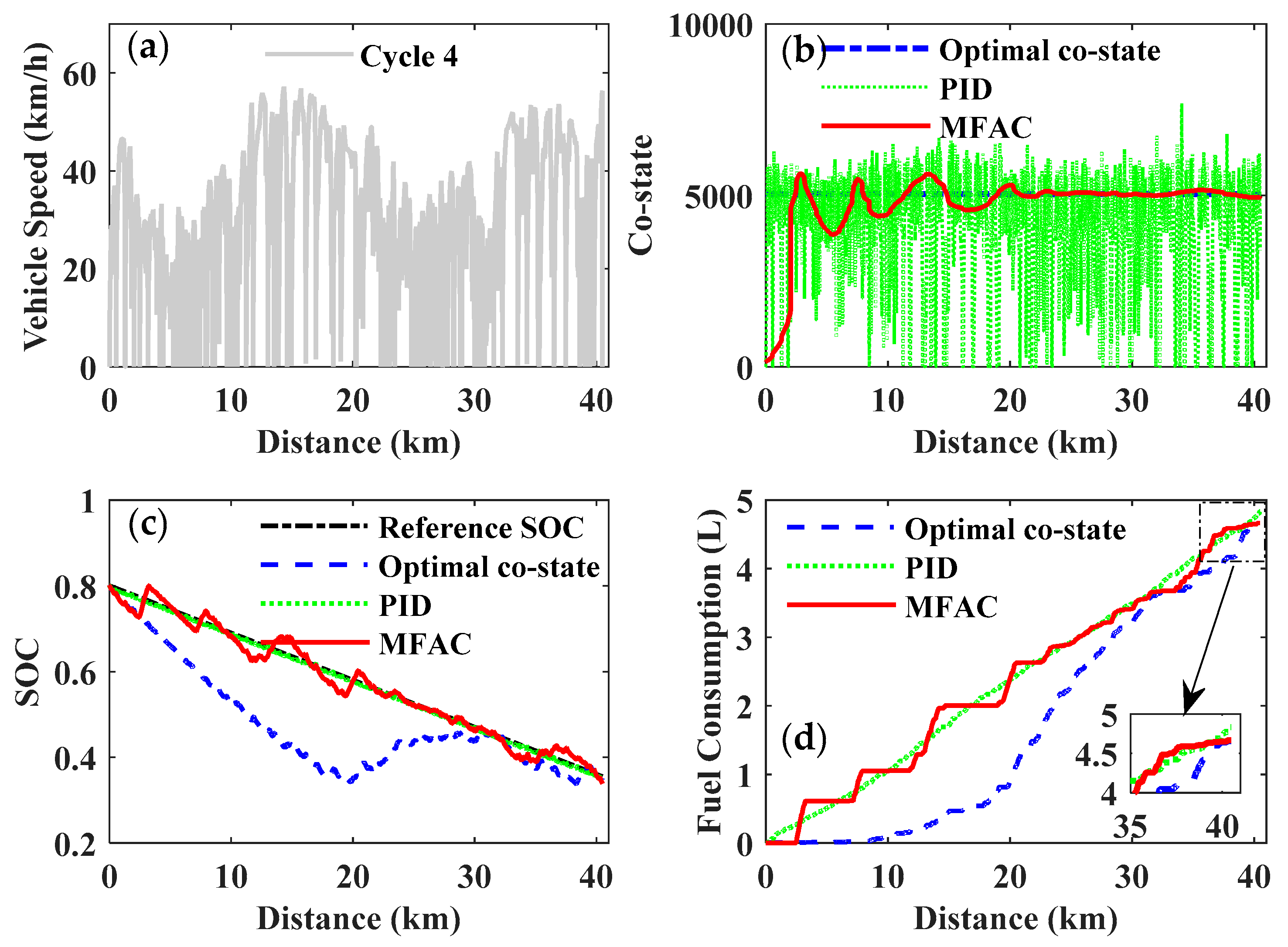
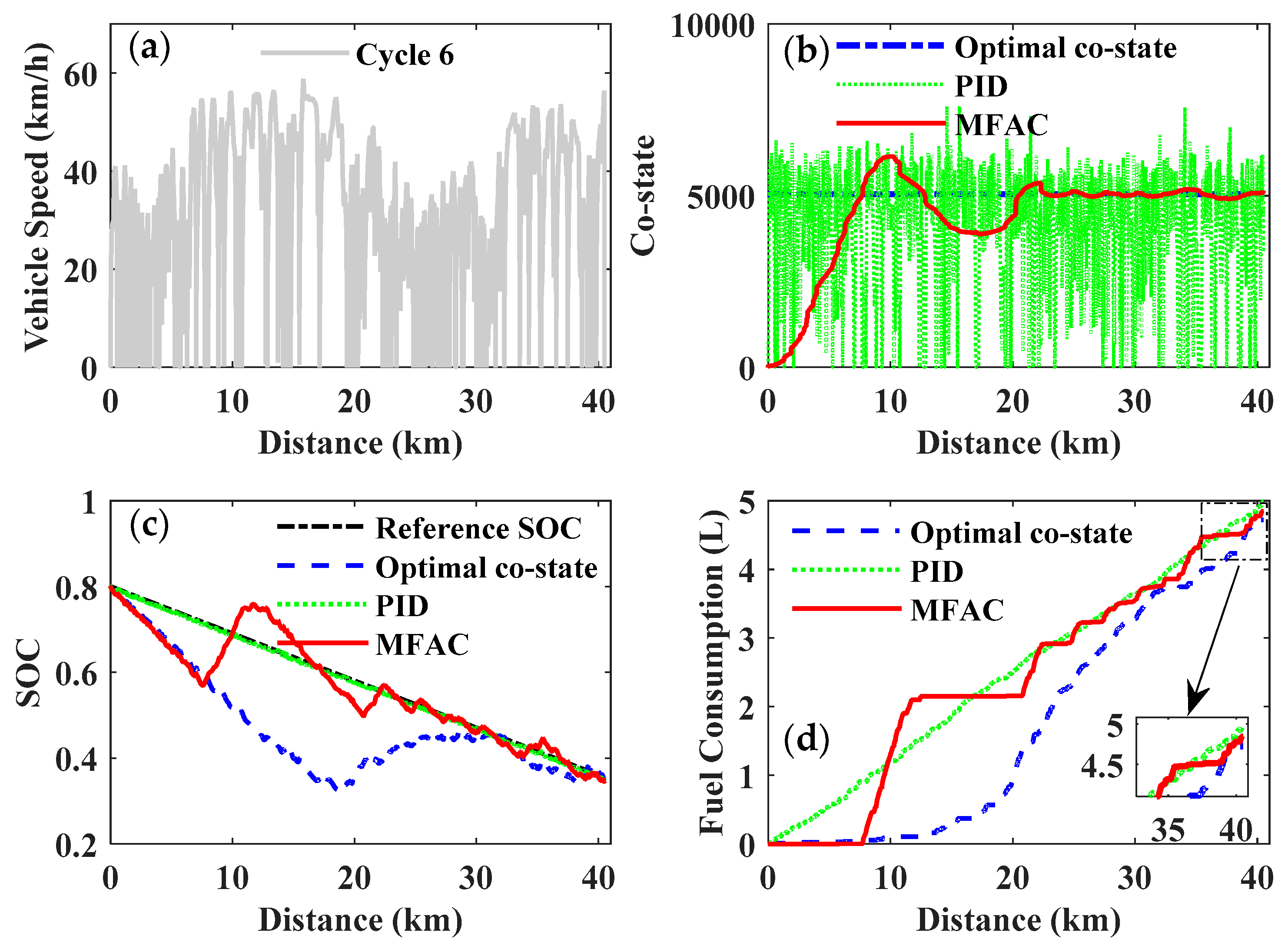
To verify the applicability and reliability of the real-time PMP-based EMS controlled by the MFAC, six driving cycles with the same trip distance were chosen for simulation. As shown in Figure 18a, Figure 19a, Figure 20a, Figure 21a, Figure 22a and Figure 23a, Cycle 1 was composed of typical Chinese urban driving cycles, and Cycles 2–6 were stochastic driving cycles obtained from the researched bus route, which is given in Section 2.2. It is worth noting that the optimal co-state of the PMP is not a constant value: Due to the changing battery, the SOC will cause a variation in the open-circuit voltage and internal resistance. To simplify the problem, the primary work area of the battery was constrained within a scope from 0.3 to 0.8 in our research, and thereby the impact of the SOC on the open-circuit voltage and internal resistance was neglected according to the characteristics of the battery (as shown in Figure 8). Therefore, the constant co-states obtained from the aforementioned six driving cycles through a shooting method were regarded as the optimal co-states of the PMP to derive the optimal solution of the EMS [31]. The results were employed as a benchmark to be contrasted to the MFAC method. Moreover, a proportional-integral-differential (PID) controller, which has been widely used for self-identification control, was also applied to a real-time co-state adjustment of the mentioned problem to illustrate the advantages of the proposed MFAC method. Figure 18, Figure 19, Figure 20, Figure 21, Figure 22, Figure 23 and Figure 24 show the simulation results of different driving cycles.
As shown in Figure 18b, Figure 19b, Figure 20b, Figure 21b, Figure 22b and Figure 23b, the co-state trajectories of the three control methods were distinctly different. However, the variation tendency of the same control methods had approximate agreement with regard to different driving cycles. The co-state trajectories of the PID control and the MFAC were both adjusted around the co-state trajectory of the optimal co-state control. Moreover, a significant discovery could be concluded: The co-state trajectory of the MFAC had a smaller fluctuation with respect to the optimal co-state trajectory after a quick self-adjustment. Eventually, it gradually converged to the optimal co-state trajectory, which had no obvious correlation with the changing of the driving cycles. However, the fluctuation of the co-state trajectory for the MFAC also has a certain distinction for different driving cycles. It may have had a slight disadvantage on the further enhancement of the fuel economy of the PHEB. Nevertheless, it will be of great significance in adopting the MFAC for a real-time application of the PMP with an unknown driving cycle, as the optimal co-state trajectory can be approximately identified online with no requirements for offline calculations.
As shown in Figure 18c, Figure 19c, Figure 20c, Figure 21c, Figure 22c, Figure 23c and Figure 24c, three control methods were constrained with the same initial and terminal SOC values for different driving cycles. The feedback SOCs of the PID control and the MFAC control tracked the corresponding linear reference SOC trajectories well. Moreover, the MFAC control had more advantageous fluctuations than the PID control did with respect to the reference SOC, due to the approximate identification of the co-state in real time. This was a benefit in facilitating the feedback SOC trajectory in approaching the optimal. Moreover, the fluctuations in the feedback SOC for the MFAC corresponded to the adjustment of the co-state. In addition, the feedback SOC trajectories of the optimal co-state control were observably different from the other control methods due to the constant co-state obtained by the shooting method being the optimal control.
As shown in Figure 18d, Figure 19d, Figure 20d, Figure 21d, Figure 22d and Figure 23d, the fuel consumption of the PHEB for the selected driving cycles, controlled by three different methods, was calculated and compared. The variations in the fuel consumption curves were closely related to the changing of the feedback SOC trajectories, where the fluctuation in the fuel consumption line of the MFAC was greater than the other two control methods. Meanwhile, fuel economy was dramatically improved by the MFAC compared to the PID control.
Figure 24 and Table 5 give a comparison of fuel consumption for the selected driving cycles and also the improvement in the MFAC control compared to the optimal co-state control and the PID control. In the course of the simulation for different driving cycles, the fuel economy of the MFAC control was always superior to the PID control, while slightly inferior to the optimal co-state control. However, the optimal co-state of the PMP was strictly dependent on the given driving cycle, which is inapplicable for a real-time application of the EMS with an unknown driving cycle. Although the PID control can be utilized in real-time control of the PMP-based strategy, it cannot achieve the expected objective of improving fuel economy. Therefore, the MFAC will be a preferable and acceptable compromise to realize real-time PMP-based energy management and improve fuel economy.

6. Conclusions

In this paper, we proposed an integrated optimization methodology to optimize driveline components and energy management control in consideration of optimization design and real-time application for a PHEB. The main findings can be concluded as follows:
(1)
To decouple the interaction between the component design and the EMS, a co-optimization method that combines an NSGA-II with a DP algorithm was proposed for simultaneous optimization of the driveline parameters and EMS, based on a synthesized real-road driving cycle. The results indicated that fuel consumption and an acceleration performance of 0–50 km/h could be respectively improved by 4.71% and 4.59%. Most significantly, the optimized driveline was on the basis of a global optimal EMS;
(2)
To develop an optimal real-time EMS after the component was optimized, a novel MFAC controller was utilized for the online adjustment of the co-state to realize PMP-based energy management by tracking the properly defined reference SOC. Moreover, the solutions for the optimal co-state control and the PID control were both compared to the proposed method. Then, a validation of the proposed EMS was carried out through six different driving conditions containing one typical driving cycle and five stochastic driving cycles;
(3)
The research results demonstrated that the MFAC controller could recognize the optimal co-state of the PMP in real time while facilitating the feedback SOC in generating favorable fluctuations around the reference SOC, thereby improving fuel economy compared to the PID controller. The MFAC-based method was not an optimal solution to enhance fuel economy, contrasted to the optimal co-state control. Nevertheless, it could achieve a suboptimal performance on a real-time application of the PMP-based EMS for unknown driving cycles. Furthermore, the optimal co-state of the PMP obtained from an offline iteration calculation could be approximately identified by the MFAC in real time.
The co-optimization method with two objectives will be expanded to more objectives in future research, and more attention will be focused on the computational efficiency of the real-time control strategy. Moreover, an accurate battery model considering the lifetime and depth of discharge is also necessary for engineering applications of the proposed methodology.

Author Contributions

Conceptualization, X.L. and J.M.; formal analysis, J.M.; funding acquisition, X.Z.; methodology, X.L. and X.Z.; software, Y.Z. and K.Z.; validation, Y.H.; writing—original draft, X.L.

Funding

This research was funded by the National Key R&D Program of China (2018YFB1600701) and the Key Research and Development Program of Shaanxi (2019ZDLGY15-01, 2019ZDLGY15-02, 2018ZDCXL-GY-05-03 -01).

Acknowledgments

The authors would like to acknowledge the support of the Youth Innovation Team of Shaanxi University.

Conflicts of Interest

The authors declare no conflicts of interest.

References

  1. Fathabadi, H. Plug-in hybrid electric vehicles (PHEVs): Replacing internal combustion engine with clean and renewable energy based auxiliary power sources. IEEE Trans. Power Electron. 2018, 33, 9611–9618. [Google Scholar] [CrossRef]
  2. Chen, H.; Li, J.; Zhong, X. Effects of gasoline and polyoxymethylene dimethyl ethers blending in diesel on the combustion and emission of a common rail diesel engine. Energy 2019, 171, 981–999. [Google Scholar] [CrossRef]
  3. Hu, X.; Moura, S.J.; Murgovski, N. Integrated optimization of battery sizing, charging, and power management in plug-in hybrid electric vehicles. IEEE Trans. Contr. Syst. Technol. 2016, 24, 1036–1043. [Google Scholar] [CrossRef]
  4. Li, L.; Zhang, Y.; Yang, C. Hybrid genetic algorithm-based optimization of powertrain and control parameters of plug-in hybrid electric bus. J. Frankl. Inst. 2015, 352, 776–801. [Google Scholar] [CrossRef]
  5. Li, L.; Zhou, L.; Yang, C. A novel combinatorial optimization algorithm for energy management strategy of plug-in hybrid electric vehicle. J. Frankl. Inst. 2017, 354, 6588–6609. [Google Scholar] [CrossRef]
  6. Guo, H.; Sun, Q.; Wang, C. A systematic design and optimization method of transmission system and power management for a plug-in hybrid electric vehicle. Energy 2018, 148, 1006–1017. [Google Scholar] [CrossRef]
  7. Silvas, E.; Hofman, T.; Murgovski, N. Review of optimization strategies for system-level design in hybrid electric vehicles. IEEE Trans. Veh. Technol. 2017, 66, 57–70. [Google Scholar] [CrossRef]
  8. Bayrak, A.; Kang, N.; Papalambros, P. Decomposition-based design optimization of hybrid electric powertrain architectures: Simultaneous configuration and sizing design. J. Mech. Des. 2016, 138, 071405. [Google Scholar] [CrossRef]
  9. Trovao, J.; Pereirinha, P.; Jorge, H. A multi-level energy management system for multi-source electric vehicles–an integrated rule-based meta-heuristic approach. Appl. Energy 2013, 105, 304–318. [Google Scholar] [CrossRef]
  10. Zhang, S.; Xiong, R.; Zhang, C. An optimal structure selection and parameter design approach for a dual-motor-driven system used in an electric bus. Energy 2016, 96, 437–448. [Google Scholar] [CrossRef]
  11. Chen, Z.; Xiong, R.; Cao, J. Particle swarm optimization-based optimal power management of plug-in hybrid electric vehicles considering uncertain driving conditions. Energy 2016, 96, 197–208. [Google Scholar] [CrossRef]
  12. Hu, X.; Murgovski, N.; Johannesson, L. Comparison of three electrochemical energy buffers applied to a hybrid bus powertrain with simultaneous optimal sizing and energy management. IEEE Trans. Intell. Transp. 2014, 15, 1193–1205. [Google Scholar] [CrossRef]
  13. Tazelaar, E.; Shen, Y.; Veenhuizen, P. Sizing stack and battery of a fuel cell hybrid distribution truck. Oil Gas Sci. Technol. 2012, 67, 563–573. [Google Scholar] [CrossRef]
  14. Millo, F.; Zhao, J.; Rolando, L. Optimizing the design of a plug-in hybrid electric vehicle from the early phase: An advanced sizing methodology. Comput.-Aided Des. 2015, 12, 22–32. [Google Scholar] [CrossRef]
  15. Ebbesen, S.; Dönitz, C.; Guzzella, L. Particle swarm optimisation for hybrid electric drivetrain sizing. Int. J. Veh. Des. 2012, 58, 181–199. [Google Scholar] [CrossRef]
  16. Gao, W.; Mi, C. Hybrid vehicle design using global optimisation algorithms. Int. J. Electr. Hybrid Veh. 2007, 1, 57–70. [Google Scholar] [CrossRef]
  17. Hu, X.; Martinez, C.; Yang, Y. Charging, power management, and battery degradation mitigation in plug-in hybrid electric vehicles: A unified cost-optimal approach. Mech. Syst. Signal Process. 2017, 87, 4–16. [Google Scholar] [CrossRef]
  18. Pourabdollah, M.; Murgovski, N.; Grauers, A. Optimal sizing of a parallel PHEV powertrain. IEEE Trans. Veh. Technol. 2013, 62, 2469–2480. [Google Scholar] [CrossRef]
  19. Martinez, C.; Hu, X.; Cao, D.; Velenis, E.; Gao, B. Energy management in plug-in hybrid electric vehicles: Recent progress and a connected vehicles perspective. IEEE Trans. Veh. Technol. 2017, 66, 4534–4549. [Google Scholar] [CrossRef]
  20. Peng, J.; He, H.; Xiong, R. Rule based energy management strategy for a series-parallel plug-in hybrid electric bus optimized by dynamic programming. Appl. Energy 2016, 185, 1633–1643. [Google Scholar] [CrossRef]
  21. Wirasingha, S.; Emadi, A. Classification and review of control strategies for plug-in hybrid electric vehicles. IEEE Trans. Veh. Technol. 2011, 60, 111–122. [Google Scholar] [CrossRef]
  22. Xie, S.; Hu, X.; Qi, S.; Lang, K. An artificial neural network-enhanced energy management strategy for plug-in hybrid electric vehicles. Energy 2018, 163, 837–848. [Google Scholar] [CrossRef] [Green Version]
  23. Wang, X.; He, H.; Sun, F. Application study on the dynamic programming algorithm for energy management of plug-in hybrid electric vehicles. Energies 2015, 8, 3225–3244. [Google Scholar] [CrossRef]
  24. Li, L.; Yang, C.; Zhang, Y. Correctional DP-based energy management strategy of plug-in hybrid electric bus for city-bus route. IEEE Trans. Veh. Technol. 2015, 64, 2792–2803. [Google Scholar] [CrossRef]
  25. Onori, S.; Tribioli, L. Adaptive Pontryagin’s Minimum Principle supervisory controller design for the plug-in hybrid GM Chevrolet Volt. Appl. Energy 2015, 147, 224–234. [Google Scholar] [CrossRef]
  26. Rezaei, A.; Burl, J.; Zhou, B. Estimation of the ECMS equivalent factor bounds for hybrid electric vehicles. IEEE Trans. Control Syst. Technol. 2017, 99, 2198–2205. [Google Scholar] [CrossRef]
  27. Zhang, S.; Xiong, R.; Sun, F. Model predictive control for power management in a plug-in hybrid electric vehicle with a hybrid energy storage system. Appl. Energy 2017, 185, 1654–1662. [Google Scholar] [CrossRef]
  28. Xie, S.; Hu, X.; Xin, Z.; Li, L. Time-efficient stochastic model predictive energy management for a plug-in hybrid electric bus with adaptive reference state-of-charge advisory. IEEE Trans. Veh. Technol. 2018, 67, 5671–5682. [Google Scholar] [CrossRef]
  29. Li, L.; Yan, B.; Yang, C. Application-oriented stochastic energy management for plug-in hybrid electric bus with AMT. IEEE Trans. Veh. Technol. 2016, 65, 4459–4470. [Google Scholar] [CrossRef]
  30. Xiong, R.; Cao, J.; Yu, Q. Reinforcement learning-based real-time power management for hybrid energy storage system in the plug-in hybrid electric vehicle. Appl. Energy 2018, 211, 538–548. [Google Scholar] [CrossRef]
  31. Xie, S.; Li, H.; Xin, Z. A Pontryagin Minimum Principle-based adaptive equivalent consumption minimum strategy for a plug-in hybrid electric bus on a fixed route. Energies 2017, 10, 1379. [Google Scholar] [CrossRef]
  32. Zhou, W.; Zhang, C.; Li, J.; Fathy, H. A pseudospectral strategy for optimal power management in series hybrid electric powertrains. IEEE Trans. Veh. Technol. 2016, 65, 4813–4825. [Google Scholar] [CrossRef]
  33. Zhang, J.; Zheng, C.; Cha, S. Co-state variable determination in Pontryagin’s Minimum Principle for energy management of hybrid vehicles. Int. J. Precis. Eng. Manuf. 2016, 17, 1215–1222. [Google Scholar] [CrossRef]
  34. Zhang, F.; Liu, H.; Hu, Y.; Xi, J. A Supervisory control algorithm of hybrid electric vehicle based on adaptive equivalent consumption minimization strategy with fuzzy PI. Energies 2016, 9, 919. [Google Scholar] [CrossRef]
  35. Tang, L.; Rizzoni, G.; Onori, S. Energy management strategy for HEVs including battery life optimization. IEEE Trans. Transp. Electrif. 2015, 1, 211–222. [Google Scholar] [CrossRef]
  36. Yang, C.; Du, S.; Li, L. Adaptive real-time optimal energy management strategy based on equivalent factors optimization for plug-in hybrid electric vehicle. Appl. Energy 2017, 203, 883–896. [Google Scholar] [CrossRef]
  37. Sun, C.; Hu, X.; Moura, S.; Sun, F. Velocity predictors for predictive energy management in hybrid electric vehicles. IEEE Trans. Control Syst. Technol. 2015, 23, 1197–1204. [Google Scholar]
  38. Ouddah, N.; Adouane, L.; Abdrakhmanov, R. From offline to adaptive online energy management strategy of hybrid vehicle using Pontryagin’s Minimum Principle. Int. J. Automot. Technol. 2018, 19, 571–584. [Google Scholar] [CrossRef]
  39. Lin, C.C.; Peng, H.; Grizzle, J.W.; Kong, J.-M. Power management strategy for a parallel hybrid electric truck. IEEE Trans. Control Syst. Technol. 2003, 11, 839–849. [Google Scholar]
  40. Sundstrom, O.; Ambuhl, D.; Guzzella, L. On implementation of Dynamic Programming for optimal control problems with final state constraints. Oil Gas Sci. Technol. 2010, 65, 91–102. [Google Scholar] [CrossRef]
  41. Kim, N.; Cha, S.; Peng, H. Optimal control of hybrid electric vehicles based on Pontryagin’s Minimum Principle. IEEE Trans. Control Syst. Technol. 2011, 19, 1279–1287. [Google Scholar]
  42. Zhao, X.; Ma, J.; Wang, S. Developing an electric vehicle urban driving cycle to study differences in energy consumption. Environ. Sci. Pollut. Res. 2019, 26, 13839–13853. [Google Scholar] [CrossRef] [PubMed]
  43. Zhao, X.; Yu, Q.; Ma, J. Development of a representative EV urban driving cycle based on a k-means and SVM hybrid clustering algorithm. J. Adv. Transp. 2018, 2018, 18. [Google Scholar] [CrossRef]
  44. Lee, T.; Adornato, B.; Filipi, Z. Synthesis of real-world driving cycles and their use for estimating PHEV energy consumption and charging opportunities: Case study for midwest/U.S. IEEE Trans. Veh. Technol. 2011, 60, 4153–4163. [Google Scholar] [CrossRef]
  45. Pires, D.; Antunes, C.; Martins, A. NSGA-II with local search for a multi-objective reactive power compensation problem. Int. J. Electr. Power 2012, 43, 313–324. [Google Scholar] [CrossRef]
  46. Zhao, W.; Luan, Z.; Wang, C. Parametric optimization of novel electric-hydraulic hybrid steering system based on a shuffled particle swarm optimization algorithm. J. Clean. Prod. 2018, 186, 865–876. [Google Scholar] [CrossRef]
  47. Li, Y.; Lu, X.; Kar, N. Rule-Based control strategy with novel parameters optimization using NSGA-II for power-split PHEV operation cost minimization. IEEE Trans. Veh. Technol. 2014, 63, 3051–3061. [Google Scholar] [CrossRef]
  48. Deb, K.; Pratap, A.; Agarwal, S.; Meyarivan, T. A Fast and Elitist Multiobjective Genetic Algorithm: NSGA-II. IEEE Trans. Evol. Comput. 2002, 6, 182–197. [Google Scholar] [CrossRef]
  49. Xie, S.; Hu, X.; Xin, Z.; James, B. Pontryagin’s minimum principle based model predictive control of energy management for a plug-in hybrid electric bus. Appl. Energy 2019, 236, 893–905. [Google Scholar] [CrossRef]
  50. Hou, Z.; Jin, S. Data-driven model-free adaptive control for a class of MIMO nonlinear discrete-time systems. IEEE Trans. Neural Netw. 2011, 22, 2173–2188. [Google Scholar]
  51. Dong, Z.; Pan, Y.; Zhang, Z. Model-free adaptive control law for nuclear superheated-steam supply systems. Energy 2017, 135, 53–67. [Google Scholar] [CrossRef]
Figure 1. Process of integrated optimization.
Processes 07 00477 g001
Figure 2. Measurement of the historical driving data.
Processes 07 00477 g002
Figure 3. Main process of the driving cycle synthesis.
Processes 07 00477 g003
Figure 4. The configuration of the studied plug-in hybrid electric bus (PHEB).
Processes 07 00477 g004
Figure 5. Brake-specific fuel consumption map of the engine.
Processes 07 00477 g005
Figure 6. Efficiency map of the motor.
Processes 07 00477 g006
Figure 7. The simplified internal resistance battery model.
Processes 07 00477 g007
Figure 8. Characteristic curves of a lithium-ion battery pack.
Processes 07 00477 g008
Figure 9. The framework of the co-optimization design.
Processes 07 00477 g009
Figure 10. Response (fuel consumption). (a) Effect on fuel consumption (%); (b) Main effect.
Processes 07 00477 g010
Figure 11. Response (acceleration time). (a) Effect on acceleration time (%); (b) Main effect.
Processes 07 00477 g011
Figure 12. Pareto front of the nondominated sorting genetic algorithm-II (NSGA-II).
Processes 07 00477 g012
Figure 13. The optimal speed ratios.
Processes 07 00477 g013
Figure 14. Optimal speed ratios and optimal objectives with respect to the weight factor. (a) Optimal speed ratios; (b) Optimal objectives.
Processes 07 00477 g014
Figure 15. The optimal economic gear shifting schedule.
Processes 07 00477 g015
Figure 16. Scheme of Pontryagin’s minimum principle (PMP)-based energy management.
Processes 07 00477 g016
Figure 17. Model-free adaptive control (MFAC) scheme based on the PMP strategy.
Processes 07 00477 g017
Figure 18. The simulation results of driving Cycle 1. (a) Driving cycle; (b) Co-state; (c) SOC; (d) Fuel consumption.
Processes 07 00477 g018
Figure 19. The simulation results of driving Cycle 2. (a) Driving cycle; (b) Co-state; (c) SOC; (d) Fuel consumption.
Processes 07 00477 g019
Figure 20. The simulation results of driving Cycle 3. (a) Driving cycle; (b) Co-state; (c) SOC; (d) Fuel consumption.
Processes 07 00477 g020
Figure 21. The simulation results of driving Cycle 4. (a) Driving cycle; (b) Co-state; (c) SOC; (d) Fuel consumption.
Processes 07 00477 g021
Figure 22. The simulation results of driving Cycle 5. (a) Driving cycle; (b) Co-state; (c) SOC; (d) Fuel consumption.
Processes 07 00477 g022
Figure 23. The simulation results of driving Cycle 6. (a) Driving cycle; (b) Co-state; (c) SOC; (d) Fuel consumption.
Processes 07 00477 g023
Figure 24. Fuel consumption comparison of three control methods.
Processes 07 00477 g024
Table 1. Main parameters of the PHEB.
ItemsDescription
VehicleCurb mass: 12,500 kg, gross mass: 16,500 kg
EngineMax torque: 850 Nm, max power: 162 kW
MotorMax torque: 850 Nm, max power: 130 kW
AMTFour-speed, speed ratio: 3.64/2.29/1.32/0.75
Final driveSpeed ratio: 5.785
BatteryCapacity: 50 Ah, voltage: 384 V
Table 2. The boundaries of the optimization parameters.
Speed RatiosGear 1Gear 2Gear 3Gear 4Final Drive
The current ratios3.642.291.320.755.785
The upper boundary4.23.01.81.06.5
The lower boundary3.22.21.20.75.5
Table 3. Initial parameter settings.
OptionValue
Population size50
Number of generations20
Crossover probability0.9
Mutation probability0.01
Table 4. A comparison of the optimization results.
CurrentBest-Found PointImprovement
Gear 13.644.2
Gear 22.292.26
Gear 31.321.45
Gear 40.751
Final drive5.7856.5
Fuel consumption (L/100 km)12.22611.7654.71%
Acceleration time (s)19.7418.8344.59%
Table 5. Fuel consumption improvement of the MFAC.
Improvement (%)
Cycle 1Cycle 2Cycle 3Cycle 4Cycle 5Cycle 6
MFAC versus optimal co-state−2.42−2.18−5.65−0.20−2.91−2.57
MFAC versus PID 4.281.523.013.431.102.83