Abstract
Combinations of spherical vessels and pipes are frequently employed in industries. Scholars have primarily studied gas explosions in closed vessels and pipes. However, knowledge of combined spherical vessel and pipe systems is limited. Therefore, a flame acceleration simulator was implemented with computational fluid dynamics software and was employed to conduct natural gas explosions in three structures, including a single spherical vessel, a single spherical vessel with a pipe connected to it, and a big spherical vessel connected to a small spherical vessel with a pipe. These simulations reflected physical experiments conducted by at Nanjing Tech University. By changing the sizes of vessels, lengths of pipes, and ignition positions in linked vessels, we obtained relevant laws for the time, pressure, temperature, and concentrations of combustion products. Moreover, the processes of natural gas explosions in different structures were obtained from simulation results. Simulation results agreed strongly with corresponding experimental data, validating the reliability of simulation.
1. Introduction
Flammable gases are employed extensively in the production of petrochemicals, and regularly stored and transported using linked vessels. A typical linked system comprises closed vessels connected with pipelines [1]. However, widespread fires and explosions frequently occur in such structures because the flames and shock waves that result from local gas explosions can propagate through the pipeline [2,3,4]. Although the prevention and mitigation techniques for fires and explosions have been continuously improving, the number of accidents has not decreased in recent years. For instance, an explosion and a fire accident caused by a gas leak considerably damaged two nearby buildings, on 23 December 2008, in a coal gasification plant in Hunan province in China [5]. Furthermore, an explosion occurred in 2013 in Dalian Bay, China, due to an operation that violated safety protocols and ignited flammable gases in a vessel, which caused the death of two individuals and severely injured two others. The explosion that occurred in natural gas pipes in 2017 in Guizhou Province, China, caused the death of eight individuals and injured 35 individuals. Therefore, conducting further studies on gas explosions occurring in linked vessels is of substantial importance for preventing and mitigating the damage caused by gas explosions.
Research on the structure of linked vessels has been conducted in past decades. Generally, compared with methane explosions occurring in vented single vessels, gas explosions in linked vessel systems constitute a complex process. This complexity can lead to high explosion strength in linked vessels [6]. Furthermore, numerous influential factors, including venting sizes and positions, ignition positions, and pipe lengths, could affect this process, among which ignition positions or obstacles could considerably change flame propagation, accelerate the speed of fire, and rapidly increase explosion pressures [7,8,9,10,11,12]. The venting size and position also play a prominent role in gas explosions [13,14,15,16,17,18]. Studies have demonstrated that the pressure piling exists in linked vessels, and the explosion strength is principally affected by the pipe length to volume ratio [19,20,21,22,23,24,25].
Currently, along with the development of computer techniques, numerical simulations have become more advanced. Numerical simulation has numerous advantages over physical testing; numerically simulated experiments are cost-effective, user-friendly, and compatible with a limitless number of experimental devices. Some scholars have examined gas explosions by using numerical simulations. With experimental data collected from the literature and the computational fluid dynamics (CFD) software AutoReaGas, Maremonti et al. [24] simulated gas explosions in two linked vessels. They not only demonstrated that turbulence induced in the second vessel was a major factor influencing violence of the explosion but also verified the validity of their CFD code. Deng et al. [25] conducted an explosion experiment with a CH4 and CO mixture in a 20-L nearly-spherical tank and then used flame acceleration simulator (FLACS) software to mimic the gas explosion of the experiment. They compared their simulation results with experimental data to prove the reliability of the simulation. Ferrara et al. [26] modeled gas explosions vented through ducts by using a two-dimensional (2D) axisymmetric CFD model based on the unsteady Reynolds-averaged Navier–Stokes approach. Simulation results evidenced that the severity of ducted explosions is mainly influenced by vigorous secondary explosions occurring in the duct. Valeria et al. [27] used a validated large-eddy simulation model to study the mechanism underlying vented gas explosions in the presence of obstacles. Methane–air mixtures with different composition ratios, variously shaped obstacles, and area block ratios were investigated. The influences of the combustion rate and venting rate on both the number and intensity of overpressure peaks were observed.
In this study, to systematically analyze how the vessel size, vessel structure, ignition position, and length of connection pipes influence natural gas explosions, the strongly validated N–S solver tool of FLACS [28], which has been developed continuously for more than 40 years for predicting the consequences of gas explosions [29,30], was employed. This tool includes a three-dimensional CFD code that solves Favre-averaged transport equations for mass, momentum, enthalpy, turbulent kinetic energy, rate of dissipation of turbulent kinetic energy, mass-fraction of fuel, and mixture-fraction on a structured Cartesian grid using a finite volume method. The Reynolds-averaged Navier-Stokes equations are closed by invoking the ideal gas equation of state and the standard k–ε model for turbulence. Furthermore, one of the key features that distinguishes FLACS from most commercial CFD codes is the use of the distributed porosity concept for representing complex geometries on relatively coarse computational meshes [28]. With this approach, large objects and walls are represented on-grid, whereas smaller objects are represented sub-grid. The pre-processor Porcalc reads the grid and geometry files and assigns volume and area porosities to each rectangular grid cell. In the simulations, the porosity field represents the local congestion and confinement, and this allows sub-grid objects to contribute with flow resistance (drag), turbulence generation and flame folding in the simulations.
Simulated-pressure data were compared with the experimental results received from Nanjing Tech University, where the explosion experiment with 10 vol% methane was conducted [13]. In addition, results revealed the distributions of temperature and concentrations of gas products occurring during gas explosions. This study mainly aimed to contribute to this research field by exploring the characteristics of gas explosion in linked vessels.
2. Simulation Objects
2.1. Experimental Apparatus and Geometric Model
The special-designed experimental device and its size and structure are displayed in Figure 1. This experimental system consisted of two different spherical vessels, where one is big and the other is small comparatively, and they connected each other with pipes having a varied length [13].
Figure 1.
Picture and schematic diagram of the experimental device for the gas explosion. (a) Photo of the experimental device; (b) scheme structural diagram of linked vessels.
Two spherical vessels were fabricated from steel with a design pressure of 20 MPa and their internal diameters were 0.6 and 0.35 m (0.113 m3 and 0.022 m3 in volume, respectively). Seamless steel pipes, with an inner diameter and a thickness of 0.06 and 0.015 m, respectively, were connected using flanges and bolts. The pipes were divided into three parts (each part was 2 m in length), so that they could be combined into pipes with varied lengths of 2.45, 4.45, and 6.45 m between the big and small spherical vessels. Suitable monitor points were placed as dictated by the experiment. The entire explosion reactor with three different structures and the mesh are given in Figure 2.
Figure 2.
Grid division on the model of the three structures. (a) Grid division on the model of the spherical vessel; (b) grid division on the model of the single sphere with a pipe; (c) grid division on the model of the big vessel connected with the small vessel.
Although only pressure data could be obtained from the experiment, the data regarding the temperature and explosion products were determined through numerical simulation. It provided further analysis and prediction dealing with unidentified explosion processes in linked vessels.
Based on the physical experiments, this study conducted natural gas explosions in three systems, which were a single spherical vessel, a single spherical vessel connected with a pipe, and a big spherical vessel connected to a small spherical vessel, individually. Meanwhile, multiple influence factors, including different structures, sizes of the vessels, lengths of the connection pipes, and ignition positions were investigated in detail.
2.2. Boundary Conditions and Initial Conditions
According to the experimental conditions and the FLACS User’s Manual [28], the initial conditions were set as standard pressure and temperature and the boundary conditions were set as Euler equations (inviscid flow equations), which is suitable for most explosion simulations. In FLACS, Euler equations are discretized for a boundary element. Namely, the momentum and continuity equations are solved on the boundary in the case of outflow. The concentration of methane used in the experiment was 10 vol%, and the vessel was filled entirely with the gas mixture. The parameter for the relative fuel–oxygen concentration employed in FLACS is denoted by equivalence ratio (ER), which is defined in Equation (1):
where m is the gas mass and V is the gas volume. Accordingly, the ER of methane–oxygen was 1.058. In addition, the default choice of heat switch is close in FLACS, as large-scale explosions are not much influenced. Activating radiation model will let walls and objects have background temperature, and gas heat loss from radiation will calculate as well as radiation from hot objects around. This is useful for small-scale confined explosions with important heat effects and is suitable to apply in this study. Furthermore, based on the experiment results in small closed vessels, Luo et al. [31] confirmed that adding a radiation model is an effective way to improve the precision of calculated results. They found that the simulation results without adding the radiation model had a large error with an average error of 10.05%, while the simulation results with adding the radiation model had a small error with an average error of 1.88%. Therefore, adding a radiation model to the simulation of gas explosions was able to produce a sound agreement with experimental results. As a result, to examine a realistic situation, this study included a radiation model to improve the accuracy of the results.
3. Simulation Results with Different Structures
3.1. Simulation Results in the Single Spherical Vessel
3.1.1. Influence of Vessel Size on the Explosion Pressure
The center of the large sphere was at (0.35, 0.35, 0.35); the sensor mounted on the sidewall was at (0.075, 0.35, 0.35); the center of small sphere was at (0.19, 0.19, 0.19); and the sensor mounted on the sidewall was at (0.025, 0.19, 0.19). The simulation was performed following the methane explosion experiment at 10 vol% in two single vessels. The results of the simulation are plotted in Figure 3.
Figure 3.
Natural gas explosion pressure varying with time in two single vessels.
The results revealed that the pressure plots at the center of the spheres and the sensor on the sidewall could be superposed. As shown in Figure 3, a nearly consistent maximum explosion pressure can be observed in the big/small vessel, which were 7.78 and 7.79 barg, respectively. However, the maximum explosion pressure in two vessels peaked at 102.9 and 53.6 ms, respectively, and there was a considerable difference of 49.3 ms, where the amplitude can be attained to 48%. Therefore, the rate of pressure rise in the big vessel was lower than that of the small vessel. As a result, without changing the initial conditions of the scenario, the peak pressure was same, but by contrast, the rate of the pressure rise was only relevant to the vessel size. Additionally, this finding was consistent with the “explosion cubic law” [32].
3.1.2. Simulation Results of the Explosion Parameters in the Single Vessel
The distributions on the X-Y section of explosion parameters containing pressure, temperature, and explosion products at the 10 vol% CH4 mixture in the big vessel are presented in Figure 4.
Figure 4.
Contours of the natural gas explosion parameters containing pressure, temperature, and concentration of products in the larger vessel. (a) Distribution of pressure; (b) distribution of temperature; (c) distribution of the concentration of products.
As evidenced in Figure 4a, the pressure in the larger vessel was practically uniform at any specific time. The explosion wave expanded into a spherical wave and the temperature was high near the igniter but gradually decreased until it approached the leading edge of the combustion wave in Figure 4b. Here, the combustion wave reached the sidewall at 125 ms. The temperature in the big vessel began to decrease when the explosion ended. As indicated in Figure 4c, when more natural gas participated in the reaction, the distribution of the explosion products spread further until the gas was consumed. The laws of the distribution of pressure, temperature, and explosion products in the small vessel were the same as those in the big vessel.
The changing temperatures and concentrations of the explosion products in the vessels are plotted in Figure 5. When the explosion occurred, the temperature at the center of the vessel enhanced rapidly, reaching 2161 K at 6 ms. Then the rate of the temperature rise dropped, and the temperature at the center of the small vessel reached 2580 K at 53 ms, whereas in the big vessel it reached 2581 K at 101 ms. The center and sidewall reached the highest temperature simultaneously, but the energy was lost when the combustion wave contacted the sidewall. The highest temperature near the sidewall was lower than that at the center of the sphere. After it was ignited at the center of the sphere, the concentration of products at the center escalated promptly, reaching its highest value (27.7%) at 12 ms in Figure 5b. The theoretical concentration of products reached 28.35% based on the methane combustion chemical equation. Accordingly, the simulation results fitted the theoretical values.
Figure 5.
Profiles of the natural gas explosion parameters in the single vessel. (a) Profiles of explosion temperatures against time in the vessels; (b) concentration profiles against time for the explosion products in the vessels.
3.2. Simulation Results in for Single Vessel with Pipes Connected to IT
3.2.1. Simulation Results of the Explosion Parameters in the Single Vessel with Pipes Connected to It
The big sphere with the 4.25-m pipe was adopted as an example; the igniter was located at the center of the sphere. The distributions of the pressure, temperature, and concentration of products of the methane explosion are shown in Figure 6. The plots of the explosion temperature and the concentration of products are delineated in Figure 7.
Figure 6.
Contours of the natural gas explosion parameters (pressure, temperature, and concentration of products) in the single vessel with a pipe connected to it; (a) distribution of pressure. (b) distribution of temperature; (c) distribution of the concentration of products.
Figure 7.
Profiles of the natural gas explosion parameters (temperature and concentration of products) in the single vessel with a pipe connected to it.
Figure 6a shows that the peak pressure in the single vessel with a pipe connected to it was lower than that of the single vessel. As provided by Figure 6b, because of the oscillation sparked by the blast, the gas in the pipe was carried to the vessel, and a jet flow formed. Moreover, from Figure 6c, when the ignition source was located at the center of the vessel, the combustion wave spread 2.3 m in the pipe when it spread from the center to the sidewall in the vessel. Therefore, compared with the vessels alone, the pipes significantly accelerated the spread of the explosion.
In virtue of the oscillation of the explosion, the plots of temperature displayed a fluctuation at the center of the vessel (in Figure 7a). Moreover, the energy was lost when the combustion wave contacted the sidewall. The highest temperature near the sidewall was low and the fluctuations were small comparatively. The plots in Figure 7b reveal that as the explosion wave spread, the entire vessel was filled with combustion products, which reflected that the variation of products was not be affected by the oscillation.
3.2.2. Influence of Changing the Ignition Position
The big vessel with the 4.25-m pipe was adopted as an example, the gas was ignited at the sidewall of the big vessel, the center of the sphere, location 1, and location 2 (in Figure 2). The plots of the explosion pressure as it changed with time are illustrated in Figure 8.
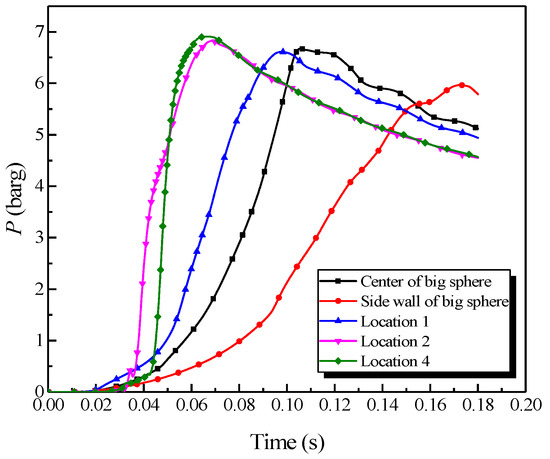
Figure 8.
Natural gas explosion pressure versus time by changing the ignition positions.
As revealed in Figure 8, changing the ignition position substantially influenced the explosion pressure in the big vessel. The peak pressure locations in the big vessel with different ignition positions could be sorted from highest to lowest as follows: location 4, location 2, the center, location 1, and the sidewall, orderly. By contrast, the maximum rate of pressure rise could be sorted as follows: location 4, location 2, location 1, the center, and the sidewall, orderly. The combustion wave contacted the sidewall during the explosion when the ignition source was located at the sidewall. Due to the wall effect, the abundant energy was consumed, which resulted in the explosion intensity to be weaker than at the other ignition positions. Accordingly, the explosion pressure and the rate of pressure rise were diminished. Locations 1, 2, and 4 were located within the pipe, where the explosion occurred with a tighter constraint and the pipes accelerated the explosion wave. Location 4 was at the end of the pipe, at which the acceleration distance was the longest. The explosion intensity was most vigorous when the combustion wave spread to the big vessel. Therefore, the explosion pressure and the rate of pressure rise were the largest when the ignition source was at location 4.
3.2.3. Influence of the Length of the Connection Pipes
The ignition source was located at the center of the vessel. The explosion pressure in different lengths of pipe is shown in Figure 9.
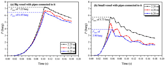
Figure 9.
Natural gas explosion pressure versus time by changing the length of the pipe connected to the single vessel.
Figure 9 shows that the size effect [33] of each pipe length had a noticeable influence on the explosion intensity in the vessel. The peak explosion pressure lessened as increasing length of the connection pipe, with the influence being the greatest in the small vessel. In any single vessel with a connected pipe, the energy from the explosion was consumed by the wall. More energy was lost when the lengths of the connected pipes increased on account of the greater area of the inner wall. Consequently, the peak explosion pressure decreased with the increase in the lengths of the connected pipes.
3.3. Simulation Results of the Big Vessel Connected to the Small Vessel
3.3.1. Simulation Results of the Explosion Parameters in the Big Vessel Connected to the Small Vessel
Regarding the simulation of the big vessel with the 4.45-m pipe and the small vessel, the ignition source was located at the center of the big vessel. Changes in the distribution of the pressure, temperature, and concentration of products are presented in Figure 10. The plots of the temperature and the concentration profiles of the explosion products are depicted in Figure 11.
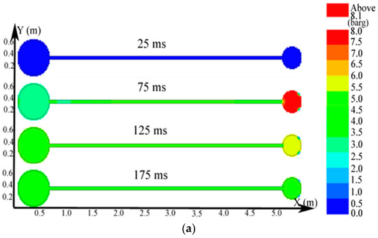
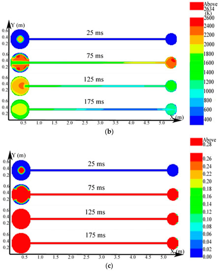
Figure 10.
Contours of the natural gas explosion parameters in the big vessel connected to the small vessel. (a) Distribution of pressure; (b) distribution of temperature; (c) distribution of the concentration of products.
Figure 11.
Profiles of the natural gas explosion parameters (temperature and concentration of products versus time) in the big vessel connected to the small vessel. (a) Profiles of explosion temperatures against time in the vessels; (b) concentration profiles against time for the explosion products in the vessels.
As illustrated in Figure 10a, the peak pressure was attained in the small vessel at 75 ms and was considerably higher than that in the big vessel. The temperature in the pipe was lower than that in the sphere because energy was absorbed by the wall in the long pipe in Figure 12b. Gas at a lower temperature was brought into the sphere as a result of the oscillation originated from the explosion wave. Here, the low-temperature jet cuts the temperature distribution in the sphere to a symmetrical structure.
Figure 12.
Natural gas explosion pressure versus time in the large and small vessels at different ignition positions.
In Figure 11a, the explosion wave reached its highest temperature (2700 K) at 70 ms in the small vessel. By contrast, the temperature was 2400 K in the big vessel at the same time. Because of the oscillation of the combustion wave, the temperature at the center of the big vessel plummeted to 1300 K at 74 ms after the combustion wave spread into the small vessel, which then formed a second peak.
Figure 11b shows that the concentration of products enhances rapidly at 62 ms. Namely, the combustion wave spread into the small vessel through the connected pipe at that moment. Furthermore, the combustion wave spread to the sidewall of the big vessel at 65 ms. This result again demonstrated the fact that the pipes accelerated the combustion wave.
3.3.2. How Changing the Ignition Position Influenced the Gas Explosion
Considering the big vessel with the 4.45-m pipe and small vessel as an example, the ignition positions were the sidewall of the big vessel, the center of the big vessel, location 1, location 2, location 4, location 6, the center of the small vessel, and the sidewall of the small vessel, as depicted in Figure 2. A methane mixture with a concentration of 10 vol% was intentionally selected in the simulations. The plots of the explosion pressure in the large and small vessels are shown in Figure 12.
As exhibited in Figure 12a, the peak pressure was attained in the big vessel when the ignition was positioned at the sidewall of the small vessel. The minimum pressure value was obtained when the ignition was positioned at the sidewall of the big vessel. Figure 12b shows that the peak pressure decreased when the ignition was moved from the sidewall in the big vessel to location 2, then the peak pressure increased slightly when the ignition was moved from location 2 to the sidewall in the small vessel. Therefore, the pressure piling [21,22] originated from the oscillation was the weakest at location 2.
3.3.3. How Changing the Length of the Connection Pipe Influenced the Gas Explosion
In the experiment, the vessel that contained the ignition source was defined as the initiating vessel, and the other was defined as the secondary vessel. The explosion results were determined variably with the change in the length of the pipe, as drawn in Figure 13.
Figure 13.
Natural gas explosion pressure-time curves in the vessels with changing the length of the pipe.
Figure 13a,b exhibited that the length of the pipe affected the pressure in the initiating vessel. The peak pressure in the initiating vessel was reached when the length of the connecting pipe was 4.45 m. As the length increased, the peak pressure in the initiating vessel increased, yet decreased when the pipe was longer than 4.45 m. The acceleration from the pipes on the combustion wave reinforced the explosion intensity, but as the length of the pipe increased, more energy was dissipated by the cause of the wall. When the length of the connecting pipe was excessive, a more momentous influence on the acceleration from the wall than that from the pipes could be demonstrated. Comparing Figure 13a together with Figure 13c,b together with Figure 13d revealed that the peak pressure in the initiating vessel was lower than that in the secondary vessel. Moreover, when the initiating vessel was the big vessel, the peak pressure in the second vessel was considerably higher.
4. Error Analysis
The simulation results and experimental data were compared for two different structures, which were the big vessel connected to the small vessel with the 4.45-m pipe and the 6.45-m pipe. The peak pressure values at different ignition positions from the simulation and experiment are shown in Figure 14.
Figure 14.
Comparison between the simulation data and experimental data of the natural gas explosion pressure versus time in the linked vessels.
In Figure 14a, “A1” to “A7” correspond to the adopted ignition positions: the sidewall of the big vessel, the center of the big vessel, location 1, location 2, location 4, the center of small vessel, and the sidewall of the small vessel. Similarly, in Figure 14b, “B1” to “B8” represent the adopted ignition positions: the sidewall of the big vessel, the center of the big vessel, location 1, location 2, location 4, location 6, the center of the small vessel, and the sidewall of the small vessel.
Figure 14 shows that the variation that depended with the ignition positions of the peak pressure in the simulation and experiment were analogous. From Figure 14a, the average error between the simulation and experimental data is 7.7% in the big vessel with the 4.45-m pipe connected to it. The average error is shown in Figure 14b is 8.04%. Overall, 70% of the simulation data were marginally larger than those of the experimental data in all the compared points, in which the average difference was 6.97%. Generally, an experiment was controlled by more factors in comparison with a simulation. Even though the radiation model was employed, with the aim of improving simulated accuracy, some degree of discrepancy still could be observed. The increase of the temperature in the wall of the pipes was limited in the physical experiment. A considerable temperature difference existed between the combustion products and the wall of the pipe. The energy was dissipated on account of thermal convection, thermal conduction, and thermal radiation. As a result, the simulation data had higher values than the experimental data [34]. Consequently, on the one hand, the simulation effectively reproduced the development of the gas explosion in linked vessel. On the other hand, it correctly predicted the variations of pressure, temperature, and the changing concentration of products with different factors.
5. Conclusions
In this study, natural gas explosions were conducted, employing the simulation tool of FLACS in three systems, including a single vessel, a single vessel with a pipe connected to it, and a big vessel connected to a small vessel with a pipe. The main conclusions of this study are as follows:
- When the explosions occurred in the same initial conditions, the peak explosion pressure maintained unchanged. However, the maximum rate of pressure rise decreased when the volume of the closed vessels increased, which is following the explosion cubic law.
- The length of the connecting pipe profoundly affected the explosion intensity in the single vessel with a pipe connected to it and in the big vessel connected to the small vessel. Furthermore, an oscillation of the explosion wave developed in the linked vessels.
- The ignition position affected the explosion intensity in the linked system extremely. The explosion intensity was weakest when the ignition source was positioned at the center of the system.
- When the explosions occurred in the linked system, the explosion intensities in the secondary vessels were stronger than those in the initiating vessels.
- Using FLACS software for the simulation of the small–scale linked system, the average difference attained 6.97%. Accordingly, the simulation results agreed reasonably well with the experimental results and the actual explosion conditions were reflected in the FLACS simulation to an acceptable extent.
Author Contributions
All authors contributed equally to the research presented in this paper and to the preparation of the final manuscript. Conceptualization, Q.W.; Formal analysis, Y.S. and X.L.; Methodology, Z.W. and M.Z.; Supervision, J.J.; Software, F.C.; Writing―original draft, Y.S. and X.L.; Writing―review, Q.W. and C.-M.S. All authors have read and agreed to the published version of the manuscript.
Funding
The study was financially supported by the National Key R &D Program of China (2016YFC0800100); the National Nature Science Foundation of China (51504190); and the Natural Science Basic Research Plan in Shaanxi Province of China (2017JM5068).
Conflicts of Interest
The authors declare no conflict of interest.
References
- Kundu, S.K. Understanding and eliminating pressure fluctuations in an extended chlor-alkali plant due to the size detail of seal pots: A design correlation. Process Saf. Environ. Prot. 2010, 88, 91–96. [Google Scholar] [CrossRef]
- Ni, T.W.; Bi, T.T.; Yang, Z.G. Failure analysis on abnormal perforation of super large diameter buried gas pipeline nearby metro. Eng. Fail. Anal. 2019, 103, 32–43. [Google Scholar] [CrossRef]
- Chen, C.H.; Sheen, Y.N.; Wang, H.Y. Case analysis of catastrophic underground pipeline gas explosion in Taiwan. Eng. Fail. Anal. 2016, 65, 39–47. [Google Scholar] [CrossRef]
- Yin, W.; Fu, G.; Yang, C.; Jiang, Z.; Zhu, K.; Gao, Y. Fatal gas explosion accidents on Chinese coal mines and the characteristics of unsafe behaviors: 2000–2014. Saf. Sci. 2017, 92, 173–179. [Google Scholar] [CrossRef]
- Zhao, X.; Chunming, J.; Yanping, W.; Jiwu, Y.; Zheng, W. Simulation study on an explosion accident in China. Process Saf. Prog. 2014, 33, 56–63. [Google Scholar] [CrossRef]
- Wang, Z.R.; Pan, M.Y.; Jiang, J.C. Experimental investigation of gas explosion in single vessel and connected vessels. J. Loss Prev. Process Ind. 2013, 26, 1094–1099. [Google Scholar] [CrossRef]
- Zhang, K.; Wang, Z.; Chen, Z.; Jiang, F.; Wang, S. Influential factors of vented explosion position on maximum explosion overpressure of methane-air mixture explosion in single spherical container and linked vessels. Process Saf. Prog. 2018, 37, 248–255. [Google Scholar] [CrossRef]
- Kindracki, J.; Kobiera, A.; Rarata, G.; Wolanski, P. Influence of ignition position and obstacles on explosion development in methane-air mixture in closed vessels. J. Loss Prev. Process Ind. 2007, 20, 551–561. [Google Scholar] [CrossRef]
- Zuo, Q.; Wang, Z.; Zhen, Y.; Zhang, S.; Cui, Y.; Jiang, J. The Effect of an Obstacle on Methane-Air Explosions in a Spherical Vessel Connected to a Pipeline. Process Saf. Prog. 2016, 36, 1–7. [Google Scholar] [CrossRef]
- Zhang, K.; Wang, Z.; Ni, L.; Cui, Y.; Zhen, Y.; Cui, Y. Effect of one obstacle on methane–air explosion in linked vessels. Process Saf. Environ. Prot. 2016, 105, 217–223. [Google Scholar] [CrossRef]
- Zhang, K.; Wang, Z.; Gong, J.; Liu, M.; Dou, Z.; Jiang, J. Experimental study of effects of ignition position, initial pressure and pipe length on H2-air explosion in linked vessels. J. Loss Prev. Process Ind. 2017, 50, 295–300. [Google Scholar] [CrossRef]
- Na’inna, A.M.; Phylaktou, H.N.; Andrews, G.E. Explosion flame acceleration over obstacles: Effects of separation distance for a range of scales. Process Saf. Environ. Prot. 2017, 107, 309–316. [Google Scholar] [CrossRef]
- Cui, Y.; Wang, Z.; Jiang, J.; Liu, X. Size effect on explosion intensity of methane-air mixture in spherical vessels and pipes. Procedia Eng. 2012, 45, 483–488. [Google Scholar] [CrossRef]
- Zhang, K.; Wang, Z.; Yan, C.; Cui, Y.; Dou, Z.; Jiang, J. Effect of size on methane-air mixture explosions and explosion suppression in spherical vessels connected with pipes. J. Loss Prev. Process Ind. 2017, 49, 785–790. [Google Scholar] [CrossRef]
- Zhang, B.; Bai, C.; Xiu, G.; Liu, Q.; Gong, G. Explosion and flame characteristics of methane/air mixtures in a large-scale vessel. Process Saf. Prog. 2014, 33, 362–368. [Google Scholar] [CrossRef]
- Yu, M.; Wan, S.; Zheng, K.; Guo, P.; Chu, T.; Wang, C. Effect of side venting areas on the methane/air explosion characteristics in a pipeline. J. Loss Prev. Process Ind. 2018, 54, 123–130. [Google Scholar] [CrossRef]
- Wan, S.; Yu, M.; Zheng, K.; Wang, C.; Yuan, Z.; Yang, X. Effect of side vent size on a methane/air explosion in an end-vented duct containing an obstacle. Exp. Therm. Fluid Sci. 2019, 101, 141–150. [Google Scholar] [CrossRef]
- Cui, Y.Y.; Wang, Z.R.; Ma, L.S.; Zhen, Y.Y.; Sun, W. Influential factors of gas explosion venting in linked vessels. J. Loss Prev. Process Ind. 2017, 46, 108–114. [Google Scholar] [CrossRef]
- Di Benedetto, A.; Salzano, E. CFD simulation of pressure piling. J. Loss Prev. Process Ind. 2010, 23, 498–506. [Google Scholar] [CrossRef]
- Di Benedetto, A.; Salzano, E.; Russo, G. Predicting pressure piling by semi-empirical correlations. Fire Saf. J. 2005, 40, 282–298. [Google Scholar] [CrossRef]
- Phylaktou, H.; Andrews, G.E. Gas explosions in linked vessels. J. Loss Prev. Process Ind. 1993, 6, 15–19. [Google Scholar] [CrossRef]
- Zhang, Q.; Jiang, J.; You, M.; Yu, Y.; Cui, Y. Experimental study on gas explosion and venting process in interconnected vessels. J. Loss Prev. Process Ind. 2013, 26, 1230–1237. [Google Scholar] [CrossRef]
- Singh, J. Gas explosions in inter-connected vessels: Pressure piling. Process Saf. Environ. Prot. Trans. Inst. Chem. Eng. Part B 1994, 72, 220–228. [Google Scholar]
- Maremonti, M.; Russo, G.; Salzano, E.; Tufano, V. Numerical simulation of gas explosions in linked vessels. J. Loss Prev. Process Ind. 1999, 12, 189–194. [Google Scholar] [CrossRef]
- Deng, J.; Cheng, F.; Song, Y.; Luo, Z.; Zhang, Y. Experimental and simulation studies on the influence of carbon monoxide on explosion characteristics of methane. J. Loss Prev. Process Ind. 2015, 36, 45–53. [Google Scholar] [CrossRef]
- Ferrara, G.; Willacy, S.K.; Phylaktou, H.N.; Andrews, G.E.; Di Benedetto, A.; Salzano, E.; Russo, G. Venting of gas explosion through relief ducts: Interaction between internal and external explosions. J. Hazard. Mater. 2008, 155, 358–368. [Google Scholar] [CrossRef]
- Di Sarli, V.; Di Benedetto, A.; Russo, G. Using Large Eddy Simulation for understanding vented gas explosions in the presence of obstacles. J. Hazard. Mater. 2009, 169, 435–442. [Google Scholar] [CrossRef]
- GexCon, A.S. FLACS V10.3 User’s Manual; GexCon AS: Bergen, Norway, 2014. [Google Scholar]
- Bleyer, A.; Taveau, J.; Djebaïli-Chaumeix, N.; Paillard, C.E.; Bentaïb, A. Comparison between FLACS explosion simulations and experiments conducted in a PWR Steam Generator casemate scale down with hydrogen gradients. Nucl. Eng. Des. 2012, 245, 189–196. [Google Scholar] [CrossRef]
- Middha, P.; Hansen, O.R.; Grune, J.; Kotchourko, A. CFD calculations of gas leak dispersion and subsequent gas explosions: Validation against ignited impinging hydrogen jet experiments. J. Hazard. Mater. 2010, 179, 84–94. [Google Scholar] [CrossRef]
- Luo, Z.M.; Zhang, Q.; Hua, W.; Cheng, F.M.; Tao, W.; Deng, J. Numerical simulation of gas explosion in confined space with FLACS. J. China Coal Soc. 2013, 38, 1381–1387. (In Chinese) [Google Scholar]
- Bartknecht, W. Dust Explosions: Course, Prevention, Protection; Springer Science & Business Media: Berlin, Germany, 2012; ISBN 3642739458. [Google Scholar]
- Ivanov, A.G. Dynamic fracture and scale effects (survey). J. Appl. Mech. Tech. Phys. 1994, 35, 430–442. [Google Scholar] [CrossRef]
- Wang, Z.R.; Jiang, J.C.; Zhou, C. Experimental investigation of gas explosion characteristic in linked vessels. Explos Shock Wave 2011, 31, 69–74. (In Chinese) [Google Scholar]


© 2020 by the authors. Licensee MDPI, Basel, Switzerland. This article is an open access article distributed under the terms and conditions of the Creative Commons Attribution (CC BY) license (http://creativecommons.org/licenses/by/4.0/).