Article

A Thermal Design of a 1 kW-Class Shell and Tube Methanol Steam Reforming System with Internal Evaporator

1
Department of Mechanical Engineering, Graduate School, Chungnam National University, Daejeon 34134, Korea
2
School of Mechanical and Automotive Engineering, Youngsan University, Yangsan-si Kyungsangnam-do 50510, Korea
3
School of Mechanical Engineering, Chungnam National University, Daejeon 34134, Korea
*
Authors to whom correspondence should be addressed.
Processes 2020, 8(11), 1509; https://doi.org/10.3390/pr8111509
Submission received: 20 October 2020 / Revised: 17 November 2020 / Accepted: 19 November 2020 / Published: 20 November 2020
(This article belongs to the Special Issue Integration of Carbon Dioxide and Hydrogen Supply Chains)

Abstract

:
Due to its low operating temperature, the performance of a methanol steam reformer depends on efficient thermal integration. In particular, the integration of the evaporator is crucial to enhance thermal efficiency. This paper presents two different configurations to utilize thermal energy for evaporation of methanol/water mixture. The reformer system is composed of a methanol steam reformer, a burner, and two different evaporators such as internal evaporator and external evaporator. Moreover, since the performance of the reforming system strongly depends on thermal utilization, a heat recovery module is designed for methanol reforming system with internal evaporator. The heat duty and steam to carbon ratio (S/C) are the variables for evaluation of its suitability. The experimental results indicate that the internal evaporator with the auxiliary heat recovery module provides stable conditions over wide operating ranges.

1. Introduction

As the use of conventional fossil fuels has triggered many environmental issues, alternative energy sources have been introduced to meet increasingly stringent related regulations. The hydrogen is an alternative energy source which has high efficiency and low emissions. Since the hydrogen is not a natural resource, it should be produced by various processes [1,2,3,4].
The methanol is a resource to produce hydrogen via a chemical reforming process. Since the methanol has high hydrogen yields with competitive energy density at a relatively low operating temperature, characteristics of methanol reforming process have been widely reported. Kinetics studies shows that the entire process entails an original methanol decomposition followed by a water gas shift reaction and, finally, the steam reforming reaction [5,6,7]. Most studies on methanol steam reforming reported kinetics of various catalysts such as Cu/ZnO and CuO/ZnO/Al2O3 [8,9,10]. They reported that catalyst sintering could be released with increasing surface area with reliable mechanical strength. Zinc oxide is known to improve the dispersion of Cu and the reducibility of CuO. The improvement of the reducibility has been proposed as a possible cause of the intense activity of CuO/ZnO catalysts [11]. The reaction kinetics and catalysis ultimately tie together for methanol reforming reaction because it can increase methanol conversion rate, lower CO concentration, and high H2 generation. Amphlett et al. present the method for achieving kinetic data for that purpose [7,10].
The characteristics of operating temperatures are also investigated such that the methanol conversion rate under 150 °C is below 10 percent. The conversion rate increases from 20 to 99 percent as the temperature is increased from 200 to 500 °C [9,11,12]. Additionally, hydrogen concentration ranges from 60% to 72%, CO concentration is under 1%, CO2 concentration is from 20% to 25% as the temperature is ranged from 220 °C to 340 °C [8]. Since those studies are concentrated on the catalyst performance, it is rarely concerned about the effect of temperature distribution in longitudinal direction, or radial direction. In the practical application of methanol reformer system, it is required to understand the temperature distribution effects which are a regime of thermal management. Furthermore, since long residence time can be depended on design of energy flow passage, it is also required to understand structural effect on the steam reforming reaction.
When the methanol reformer is applied to fuel cell application, the methanol steam reformer comprises a vaporizer, combustor, and steam reformer. The methanol mixture becomes a gas mixture in the vaporizer and is delivered to the reforming reactor. The methanol fueled combustor provides thermal energy into the methanol steam reformer. Recently, a membrane reactor has been applied to the methanol steam reformer which is known as a methanol reaction with very low CO concentrations [13,14,15]. Even though there are various studies of methanol steam reforming system in the component level, the whole system study is still scarcely reported. Additionally, the system design via simulation could be valuable to understand the whole physics, and evaluating the actual performance via experiments is still required. In the literature, the whole design process of methanol steam reforming system from simulation to experimental evaluation is rarely reported.
The objective of this study is to understand the performance of two different configurations such as a reforming system with external evaporator and a reforming system with internal evaporator. When the external evaporator is connected to the shell and tube reformer, the lower limits of operating conditions are difficult to be achieved due to a limitation of evaporation enthalpy and heavy heat losses. An internal evaporator is the other option to utilize the thermal energy of burnt gases and the lower limit of heat duty is easily resolved with auxiliary heat recovery units. Those two configurations are directly compared in terms of heat duty. After that, the performance of more competitive configuration is investigated in terms of s/c ratio.

2. Design and Experiment of Methanol Steam Reformer

Design of 1 kW Class Methanol Steam Reformer

As a steam reformer operates at a temperature from 150 to 500 °C, the methanol conversion rate is suitable for fueling a fuel cell stack. However, the appropriate operating temperature is from 250–300 °C [5] that corresponds to the composition of thermodynamic equilibrium. If the burner is equipped to provide the thermal energy to the reforming reaction, the lower temperature of the methanol steam reformer requires extra utilization of thermal energy for an efficient system.
Since reliable performances of the catalysts are required, the commercial catalysts MDC-3 produced by Clariant (Muttenz, BL, Switzerland) are used. The catalyst grain has an approximate diameter of 3.2 mm [16]. A shell-and-tube structure of the reformer enhances heat transfer. This configuration can cover a broad spectrum of temperature and pressure. This design is exceptionally beneficial for utilizing the whole surface for heat transfer within the total volume and weight. When the mixture of methanol and water enters the reformer inlet, the heat is transferred from inner hot gases to the outer surfaces of tube bunches. Since the inlet flows at the tube bunches are uniform by specially designed perforated plates, those structures contribute to uniform temperature in radial direction.
As the system scale is smaller, it is more difficult to optimize the thermal management system. Additionally, since the evaporator of the methanol steam reformer requires a huge amount of energy to evaporate methanol/water mixture, the proper thermal management is required to improve system efficiency. In this study, the methanol flow rate is determined to power 1 kWe class fuel cell such that the methanol reforming system should have proper thermal management components and configuration. The steam to carbon ratio is 2.5. The schematics of the reformer is shown in Figure 1a. The gap between the tubes in radial direction is determined experimentally by a lab-scale methanol steam reformer [16,17].
The shell side is divided into three main compartments: the heat source inlet compartment, the heat source outlet compartment, and the reforming reaction compartment. A perforated plate is placed between the reformer inlet compartment and the reforming reaction compartment to achieve uniform distribution of induced gases. The reforming inlet compartment includes an area for ceramic balls that play a role in taking more heat from the heat source tubes. The reforming reaction compartment is filled with small grains of catalysts. This compartment also contains a number of baffles to increase the residence time of the reactant gas. The material and the thickness of the shell and tubes are considered to withstand the internal and external pressure, and the inside tube can tolerate acceptable corrosion.
This study investigates the effect of two types of evaporators on system performance, such as internal evaporation and external evaporation. Figure 1b shows the external evaporator that is a planar heat exchanger with number of micro-channels. It contains four flow gates which are two outlets and two inlets. The cold side inlet allows the liquid mixture of methanol and water to be evaporated by burnt gases from methanol burner. The hot side inlet of the evaporator will take the burnt gases from the burner which has a wide temperature drop at the exit. The exit of the hot side is then connected to the heat source inlet of the reformer. Figure 1c shows the reformer with the internal evaporator which includes zirconia balls inside the reforming inlet compartment. Right after the mixture of methanol and water flows to the reformer inlet, the mixture can be evaporated by the heat from the burnt gases of the methanol combustor. When the evaporator is included inside the shell-and-tube type reformer, the induced gas temperature is very important to evaporate the methanol/water mixture. As the mixture temperature is less than 90 °C, the internal evaporator is not working properly. In this study, the auxiliary heat recovery module (AHRM) is designed to operate the evaporator stably. The auxiliary heat recovery module (AHRM) is shown in Figure 1d. This device has a shell and tube configuration with shell and tube diameter of 25.4 mm and 3.175 mm, respectively. The shell contains 14 tubes for heat source gas.
The methanol burner is designed to satisfy two criteria: the operating temperature and the flow rate so that the heat duty can be controlled appropriately. It comprises three main components, a venturi tube, a combustion chamber, and a dilution zone. Several additional components, such as a controller, an air compressor, and a pump are also adopted. After venturi tube, the methanol-air mixture goes through a combustion chamber that contains an ignitor. The dilution zone mixes combusted gases with fresh air to cool down the burner outlet gases as target temperature.
The specifications of the reformer are listed in Table 1 and the experimental operating conditions are shown in Table 2.
Figure 2 shows two experimental apparatuses for a methanol steam reforming system. Figure 2a is a reference of a methanol steam reforming system and Figure 2b is a methanol steam reforming system with an internal evaporation process and an extra heat recovery module.
In Figure 2a, the methanol burner controller operates the pump and the compressor to obtain the demanded outlet temperature. The thermal energy of the burnt gases is then supplied to the hot side inlet of the evaporator. Thermocouple 1 (TC1) is installed at the burner’s outlet. The mixture will then flow through the evaporator. At the evaporator, the burnt gases and the methanol and water mixture flow in a co-flow arrangement under phase change condition. Next, the methanol and steam mixture gas of the evaporator is supplied to the reformer inlet, and the hot burnt gases of the evaporator hot side outlet is provided to the reformer heat inlet. Another thermocouple (TC2) is installed to detect the temperature of the reformer inlet. Two other thermocouples (TC3) and (TC4) are installed to identify the temperature at the heat source outlet and the reformer outlet, respectively. The dried gas passes through a gas analyzer to examine the compositions of each component in the mixture. In Figure 2b, the methanol burner has same procedures as Figure 2a. Thermocouple 1 (TC1) is installed at the exit of the burner. Another thermo-couple (TC2) is installed to detect the temperature of reforming gases at the reformer inlet. The AHRM is placed at the exit of the reformed gases to manage stability of low heat duty condition. One thermocouple (TC3) is placed in this position (reformer heat outlet). Another thermocouple (TC4) is installed at the reformer outlet. Two more thermocouples are placed in the hot side inlet of the AHRM (TC5) and the hot side outlet of the AHRM (TC6). The real-time gas analyzer is SWG 200-1 BIOGASS produced by MRU Instruments (Humble, TX, USA), used for measuring the composition of reformed gas including H2, CO, CH4, CO2, and O2.
Figure 3 shows the whole layout of the methanol steam reforming system without AHRM (reference case). Temperatures of each component are sampled in every second, and reformed gases are sampled 12 times at the steady-state, and then those sampling data are averaged. To ensure reliability, each experiment is conducted at least two times. The experimental errors are within 1% in temperature and 3% reformed gas concentration.

3. Results and Discussion

3.1. Performance of Methanol Steam Reforming System without AHRM

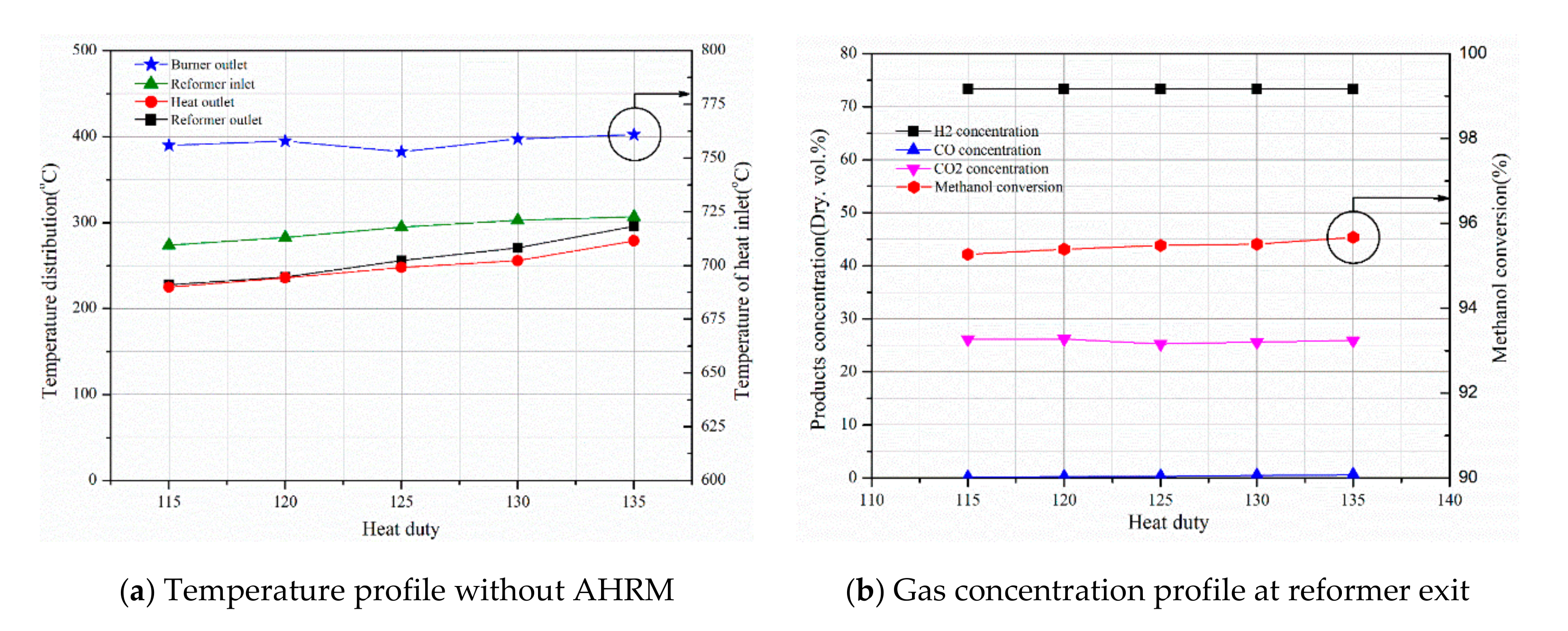
Four thermocouples are installed in the reformer system to observe its thermal behavior. Figure 4 shows the performance of methanol steam reformer system without AHRM (named reference case). This heat duty is normalized with design conditions. When the combustor’s methanol flow rate reaches 0.003 mol/s, then that heat duty is defined as a 100% load. At this condition, the adiabatic flame temperature of the burner combustion chamber is set to be 950 °C. The airflow rate of the methanol burner is determined practically by the manufacturer.
The heat duty variation is determined by experiment. As heat duty is lowered, the micro-channel evaporator absorbs most thermal energy so that the reforming reaction is scarcely activated. In this study, the heat duty is limited to 115% or higher under given operating conditions that is maintaining heat source inlet temperature stably. Below the 115% heat duty, the heat source temperature at the inlet of reforming section is not ensured to activate the steam reforming reaction of methanol. As the fuel flow rate to the burner is increased, the system thermal energy is increased. The temperatures of components are raised by an increase in the burner heat duty. As the heat duty is increased from 115% to 135% of burner fuel, the gradient of reformed gas temperature is steeper than that of other temperatures. However, as shown in Figure 4b, the concentration of hydrogen and carbon dioxide is steadily maintained. On the other hand, concentration of carbon monoxide is increased significantly about four-fold from 0.16% to 0.64%.
Since the temperature at the reformer inlet (TC 2) and outlet (TC 4) is vital to determining the amount of thermal energy consumed for the reforming reaction, those two parameters are increased with higher heat duties. In addition, the temperature of the reformer outlet (TC 4) directly affects the concentration of carbon monoxide. Thus it is necessary to control the temperature of the reformer outlet (TC 4) to reduce carbon monoxide. Even though the methanol conversation rate is increased with heat duty, the results show that hydrogen yields is not only improved but the carbon monoxide concentration is sensitive to the heat duty conditions.
The thermal efficiency of the system is as follows:
System   Thermal   Efficiency :   η = m ˙ H 2 × L H V H 2 m ˙ C H 3 O H × L H V C H 3 O H   ( % )
Figure 5 shows that the system thermal efficiency of the system in terms of heat duty. The system thermal efficiency is fairly low compared with other reforming systems. Its efficiency decreases slightly when the percentage of methanol fuel for the burner grows from 115% to 135%. However, there is an exception in which the 125% case is the largest with a value of 65.24%. At the conditions, since the methanol flow rate to the burner is lowered to maintain exit temperature, the unexpected lower methanol flow rate results in an increase in thermal efficiency which seems to control issues of the burner. Beside the heat duty condition, the system thermal efficiency is decreased slightly with increasing heat duty.

3.2. Performance of Methanol Steam Reforming System with AHRM

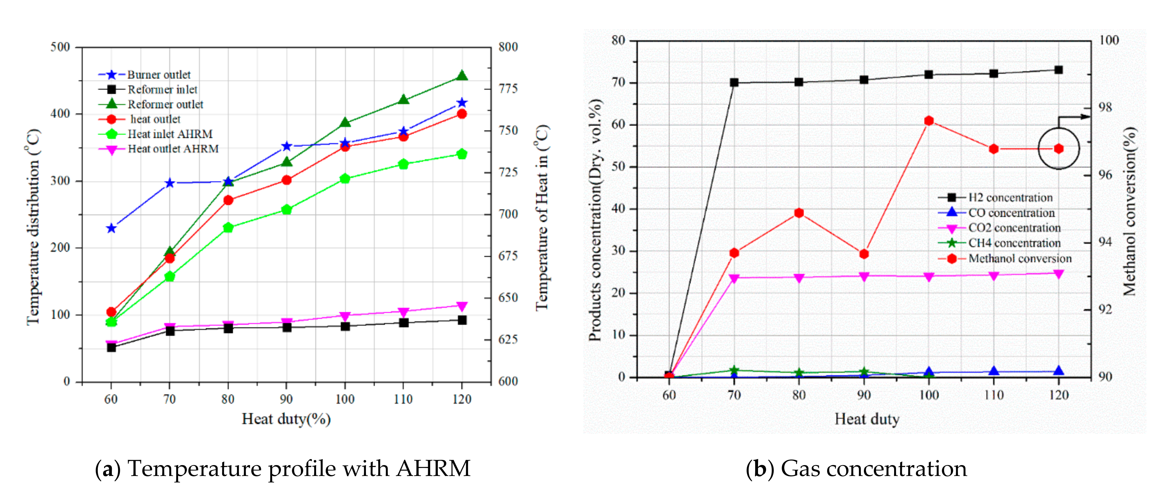
When the evaporator is placed inside the reformer body, the thermal energy utilization seems to be enhanced. The result is shown in Figure 6. As observed, the temperature of each component is stably observed over 60% heat duty conditions, a remarkable difference from the reference case. However, this remarkable change is rarely observed with the internal evaporator only. When the internal evaporator is only located with the auxiliary heat recovery module, the technical trend is almost the same as the reference case. Since the auxiliary heat recovery module (AHRM) plays a crucial role in absorbing the wasted heat, the AHRM is connected to the reforming gas inlet. The hydrogen and carbon monoxide yield rates are linearly increased with heat duty conditions. The methanol conversion rate is also increased with heat duty variation.
Compared with the reference cases, the reformer exit temperature is significantly increased. The temperature at the same heat duty, the reformer exit temperature of the reference case, is about 240 °C while the reformer exit temperature is 452 °C for the methanol reformer with AHRM. Accordingly, internal thermal energy utilization can be significantly improved with AHRM. One unique species is also observed in the methanol steam reforming with AHRM. As the heat duty is increased, the methane is observed below the 100% heat duty that seems to be the effect of catalyst selectivity.
Figure 7 shows the thermal efficiency of the whole system in terms of heat duty. The thermal efficiency of the system improves as the heat duty is lowered. The thermal efficiency of the system is linearly decreased from 77.75% to 63.89%. Compared with the reference condition at 120% heat duty, approximately 1% thermal efficiency is higher for methanol steam reformer with AHRM. Even though it may not be a big difference, it shows that an internal evaporator can improve system efficiency.

3.3. Effects of Steam to Carbon Ratio on the System Performance with Extra Heat Recovery Module

As the steam flow rate is increased, the wasted thermal energy should be reduced. Since the methanol steam reforming system with AHRM shows stable performance under various heat duty conditions, the system is applied to investigate the effect of steam to carbon ratio. The system was operated at the 80% heat duty condition. Figure 8 shows the system performance in terms of component temperature and gas concentration. It is observed that reduced heat duty decreases the burner exit temperature but the temperature of burnt gas is maintained at about 760 °C. As steam to carbon ratio is increased, the overall temperature decrease is also observed. This is because more steam production requires more evaporation enthalpy. The methanol conversion rate maximum between 2.5 S/C and 2.75 S/C it then is decreased. Since the reformer exit temperature is slowly going down, the some portion of methanol is exhausted without reaction.
On the other hand, AHRM temperatures in TC 5 and TC 6 is almost the same for all cases, which are 86 °C and 80 °C, respectively. As S/C ratio are increased, the more heat is provided into the AHRM. In the AHRM, the heat from reformer is used to increase the temperature of inlet methanol steam reformer. Accordingly, almost same amount of increase is expected in two inlets of AHRM. In Figure 8a, the heat outlet AHRM temperature and the reformer inlet temperature are the inlet temperature of AHRM which is maintained.
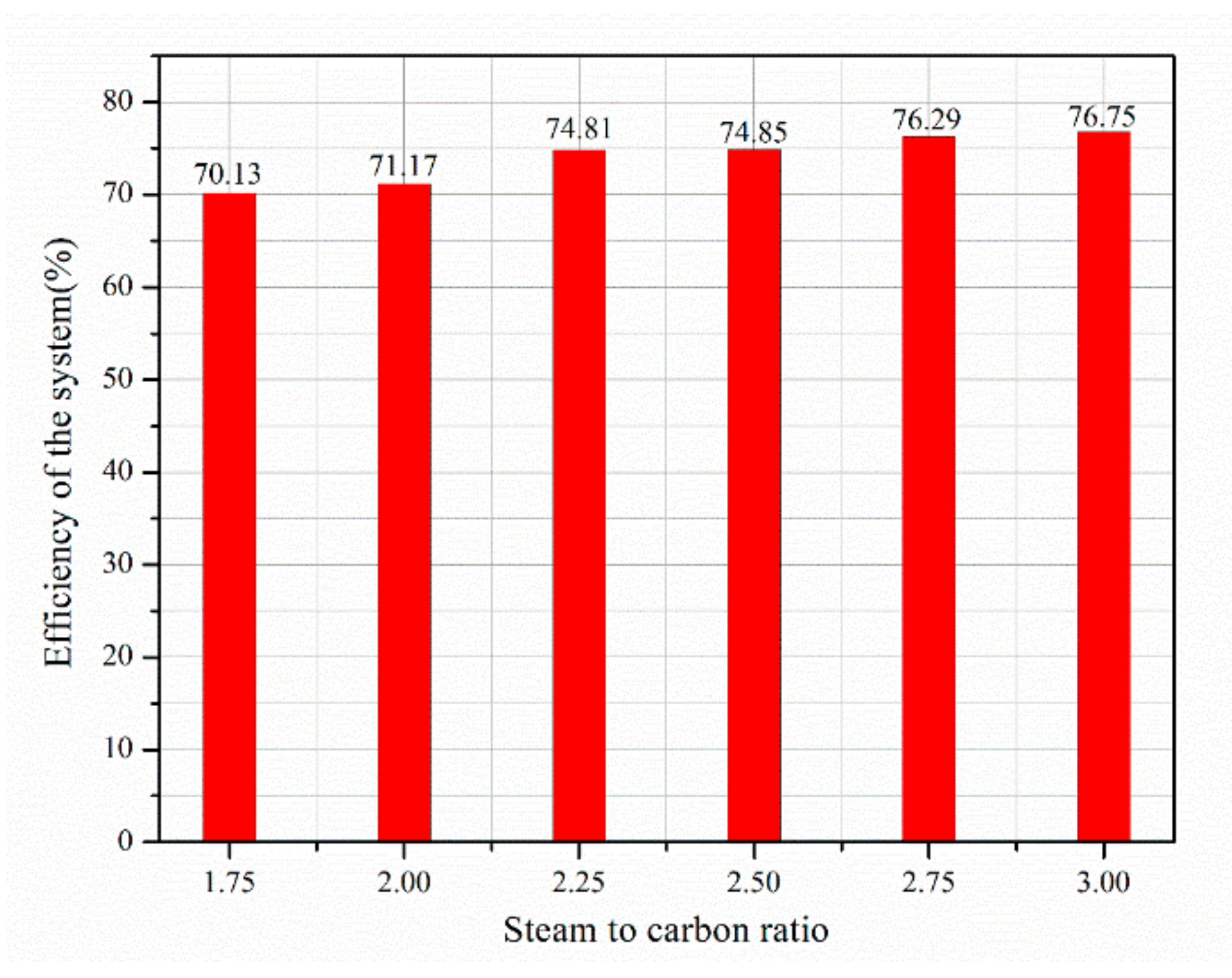
The thermal efficiency of the system should be improved with a higher S/C ratio due to the reduction in waste energy. Figure 9 shows what percentage of thermal efficiency is improved with an increasing S/C ratio. Since the evaporator is placed inside the reformer body, the evaporation of methanol-water mixture is easily conducted. As observed, the thermal efficiency is improved from about 70% to 76.8% in terms of S/C ratio. The results show that improvement of thermal efficiency does not exactly correspond to the methanol conversion rate.

4. Conclusions

In this study, a thermal management strategy of a methanol steam reforming system is investigated with two different configurations. The conclusion is as follows,
  • The auxiliary heat recovery module is useful to extend the operability of the methanol/water mixture inside the shell and tube methanol steam reformer, such that the operating range of methanol steam reformer is extended to 70% heat duty.
  • The thermal efficiency of the steam reformer with external evaporator ranges from 59.5% to 65.24%. Since the lower limit of heat duty is extended for the methanol reformer with internal evaporate, the thermal efficiency is improved to be 77.75% at 70% heat duty.
  • As the S/C ratio is increased from 1.75 to 3.0, the wasted energy of the methanol reformer with an internal evaporator is reduced. The thermal efficiency is then increased from 70.13% to 76.65% at 80% heat duty.

Author Contributions

All authors contributed to this research in collaboration. D.Y. and N.T.V. have an experiment and write manuscript, J.Y. proposed the conceptualization, and S.Y. provided substantial help with the paper schedule and gave advice on the experiment and supervised. All authors have read and agreed to the published version of the manuscript.

Funding

This research was supported by a grant from the Agency for Defense Development (ADD) (grant number: UD180051GD).

Conflicts of Interest

The authors declare no conflict of interest.

References

  1. Liang, M.; Luo, B.; Zhi, L. Application of graphene and graphene-based materials in clean energy-related devices. Int. J. Energy Res. 2009, 33, 1161–1170. [Google Scholar] [CrossRef]
  2. Molino, A.; LaRocca, V.; Chianese, S.; Musmarra, D. Biofuels Production by Biomass Gasification: A Review. Energies 2018, 11, 811. [Google Scholar] [CrossRef] [Green Version]
  3. Sikarwar, V.S.; Zhao, M.; Fennell, P.S.; Shah, N.; Donat, F. Progress in biofuel production from gasification. Prog. Energy Combust. Sci. 2017, 61, 189–248. [Google Scholar] [CrossRef]
  4. Rathour, R.K.; Ahuja, V.; Bhatia, R.K.; Bhatt, A.K. Biobutanol: New era of biofuels. Int. J. Energy Res. 2018, 42, 4532–4545. [Google Scholar] [CrossRef]
  5. Faungnawakij, K.; Kikuchi, R.; Eguchi, K. Thermodynamic evaluation of methanol steam reforming for hydrogen production. J. Power Sources 2006, 161, 87–94. [Google Scholar] [CrossRef]
  6. Agrell, J.; Birgersson, H.; Boutonnet, M. Steam reforming of methanol over a Cu/ZnO/Al2O3 catalyst: A kinetic analysis and strategies for suppression of CO formation. J. Power Sources 2002, 106, 249–257. [Google Scholar] [CrossRef]
  7. Amphlett, J.C.; Evans, M.J.; Jones, R.A.; Mann, R.F.; Weir, R.D. Hydrogen production by the catalytic steam reforming of methanol part 1: The thermodynamics. Can. J. Chem. Eng. 1981, 59, 720–727. [Google Scholar] [CrossRef]
  8. Breen, J.P.; Ross, J.R. Methanol reforming for fuel-cell applications: Development of zirconia-containing Cu–Zn–Al catalysts. Catal. Today 1999, 51, 521–533. [Google Scholar] [CrossRef]
  9. Purnama, H.; Ressler, T.; Jentoft, R.; Soerijanto, H.; Schlögl, R.; Schomäcker, R. CO formation/selectivity for steam reforming of methanol with a commercial CuO/ZnO/Al2O3 catalyst. Appl. Catal. A Gen. 2004, 259, 83–94. [Google Scholar] [CrossRef] [Green Version]
  10. Agrell, J.; Boutonnet, M.; Fierro, J.L. Production of hydrogen from methanol over binary Cu/ZnO catalysts: Part II Catalytic activity and reaction pathways. Appl. Catal. A Gen. 2003, 253, 213–223. [Google Scholar] [CrossRef]
  11. Günter, M.M.; Ressler, T.; Jentoft, R.E.; Bems, B. Redox Behavior of Copper Oxide/Zinc Oxide Catalysts in the Steam Reforming of Methanol Studied by in Situ X-Ray Diffraction and Absorption Spectroscopy. J. Catal. 2001, 203, 133–149. [Google Scholar] [CrossRef] [Green Version]
  12. Amphlett, J.C.; Mann, R.F.; Weir, R.D. Hydrogen production by the catalytic steam reforming of methanol: Part 3: Kinetics of methanol decomposition using C18HC catalyst. Can. J. Chem. Eng. 1988, 66, 950–956. [Google Scholar] [CrossRef]
  13. Wieland, I.; Melin, I.; Lamm, I. Membrane reactors for hydrogen production. Chem. Eng. Sci. 2002, 57, 1571–1576. [Google Scholar] [CrossRef]
  14. Iulianelli, A.; Ribeirinha, P.; Mendes, A.; Basile, A. Methanol steam reforming for hydrogen generation via conventional and membrane reactors: A review. Renew. Sustain. Energy Rev. 2014, 29, 355–368. [Google Scholar] [CrossRef] [Green Version]
  15. Basile, A.; Iulianelli, A.; Longo, T.; Liguori, S.; De Falco, M. Pd-based Selective Membrane State-of-the-Art. In Membrane Reactors for Hydrogen Production Processes; Springer: Berlin/Heidelberg, Germany, 2011; Volume 2, pp. 21–55. [Google Scholar]
  16. Cho, K.; Yun, J.; Yu, S. Experimental Study on Catalytic Characteristics of 1-kW Methanol Reformer. Trans. Korean Soc. Mech. Eng.B 2019, 43, 817–823. [Google Scholar] [CrossRef]
  17. Lotrič, A.; Sekavčnik, M.; Hočevar, S. Methanol Steam Reformer–High Temperature PEM Fuel Cell System Analysis. In Proceedings of the Military Green 2012 Conference-Exhibition-Demonstration Call for Exhibits and Demonstrations, Brussels, Belgium, 19–20 June 2012; p. 1000. [Google Scholar]
Figure 1. Design of methanol steam reformer, evaporator and heat recovery module.
Processes 08 01509 g001
Figure 2. Experimental apparatus for methanol steam reforming system (a) without auxiliary heat recovery module (AHRM) and (b) with AHRM.
Processes 08 01509 g002
Figure 3. Methanol steam reformer system.
Processes 08 01509 g003
Figure 4. Gas concentration and component temperature without AHRM (reference case).
Processes 08 01509 g004
Figure 5. Efficiency of the reference system with different heat duty.
Processes 08 01509 g005
Figure 6. Gas concentration and component temperature with AHRM (case of enhance thermal management).
Processes 08 01509 g006
Figure 7. Efficiency of the internally evaporated system with different heat duty with auxiliary heat recovery module.
Processes 08 01509 g007
Figure 8. Different steam to carbon ratios for reformer inlet with extra heat recovery module.
Processes 08 01509 g008
Figure 9. Efficiency of the system for different S/C ratios.
Processes 08 01509 g009
Table 1. Design parameters of the 1kWe class methanol steam reformer.
ParameterValueUnit
Flow rate of methanol at reformer inlet 5.77g/min
Flow rate of water at reformer inlet8.11g/min
Total flow rate of the system924.77L/h
Shell diameter72mm
Tube diameter6.35mm
Number of tubes38ea
Reaction zone length135mm
Reactor volume0.5470L
Tube volume0.1617L
Shell volume0.3853L
Gas hourly space velocity24001/h
Table 2. Experimental conditions of the methanol steam reformer system.
ParameterValueUnit
Reference state
Temperature of reactants for reforming25
Flow rate of methanol for reforming0.003mol/s
Flow rate of methanol for burner0.0015mol/s
Steam to carbon ratio2.5-
Gas hourly space velocity24001/h
Experimental variables
S/C ratio (SCR)1.75, 2, 2.25, 2.5, 2.75, 3-
Flow rate of methanol for burner60, 70, 80, 90, 100, 110, 120%
Publisher’s Note: MDPI stays neutral with regard to jurisdictional claims in published maps and institutional affiliations.