Article

Numerical Simulation on the Brake Effect of FAC-EMBr and EMBrRuler in the Continuous Casting Mold

1
College of Petroleum Engineering, Liaoning Shihua University, Fushun 113001, Liaoning, China
2
Materials Advanced Characterisation Centre (MACH1), College of Engineering, Swansea University, Bay Campus, Fabian Way, Swansea SA1 8EN, UK
*
Authors to whom correspondence should be addressed.
Processes 2020, 8(12), 1620; https://doi.org/10.3390/pr8121620
Submission received: 24 October 2020 / Revised: 1 December 2020 / Accepted: 2 December 2020 / Published: 9 December 2020

Abstract

:
The brake effect of the freestanding adjustable combination electromagnetic brake (FAC-EMBr) and EMBr ruler on the behavior of molten steel flow and the level fluctuation were investigated with the numerical method. The effects of the horizontal magnetic pole position (EMBr ruler), magnetic induction intensity, and casting speed on two types of electromagnetic brakes were studied. The numerical simulation results show that the magnetic field caused by the EMBr ruler is mainly distributed under the submerged entry nozzle (SEN), and it is very weak nearby the meniscus area. After the FAC-EMBr is applied, the magnetic field is mainly distributed in the area below the submerged entry nozzle, the upper roll region, and in the meniscus region. The application of the electromagnetic brake can effectively suppress the impact of the jet and decrease the molten steel velocity in the meniscus area. The brake effect of the EMBr ruler on the behavior of the molten steel flow and the level fluctuation is significantly influenced by the horizontal magnetic pole position. The increasing of the magnetic flux density can significantly increase the velocity of molten steel in the upper roll region and lead to an intense fluctuation in the steel/slag interface, as the horizontal magnetic field cannot cover the three key regions. The brake effect of the FAC-EMBr is less influenced by the variation of the process parameters due to the addition of vertical magnetic poles. Additionally, the “secondary braking effect” of the vertical magnetic poles can help to lower the increase of velocity in the upper roll region caused by the excessive magnetic induction intensity and the high casting speed. Therefore, even under the high casting speed conditions, the application of a new type of FAC-EMBr is also an efficient way to suppress the molten steel flow and level fluctuation at the meniscus area and decrease the possibility of slag entrapment.

1. Introduction

In the slab continuous casting process, the slab quality is highly related with the melt behavior in the mold [1,2,3]. Due to the involvement of the submerged entry nozzle (SEN), the jet flow from the SEN usually generates an upper roll and a downwards roll flow, separated by an impingement point nearby the narrow face (NF) of the slab mold. A strong upper roll flow can cause the fluctuation of the meniscus and further leads to the aggravation of the fluctuation of the molten steel–liquid slag interface. If the liquid slag is captured by the initially solidified shell, the internal quality defects of continuous casting slab will be formed [4,5]; however, too-low velocity in the upper roll region could result in a low and nonuniform liquid temperature distribution in the meniscus region, which is not good in terms of melting and the infiltration of mold powder, even leading to meniscus freezing and hook formation and, finally, cause the surface quality defects in the continuous casting slab [6]. For the downwards roll-flow region, nonmetallic inclusions and small argon bubbles could be trapped in the initial solidification shell zone. The internal quality defects such as cracks, slivers, and blisters in the final product will be formed, especially under high casting speeds. During the subsequent annealing processes, the trapped argon bubbles elongate during rolling and in low-strength steel and may expand to create surface blisters and “pencil pipe” defects [7,8,9,10,11]. For the impingement point region, the jet was formed when the fresh molten steel left the SEN port and impinged against the solidifying shell. The fresh molten steel carries superheat that erodes the solidifying shell and even leads to a costly breakout, where the high-temperature molten steel bursts through the solidifying shell [7]. Clearly, to control the molten steel flow behavior effectively could help to achieve a high quality of the slab.
Electromagnetic braking (EMBr) is an efficient way to control the flow in the slab mold. The so-called electromagnetic brake technology is to impose a steady magnetic field with a perpendicular direction to the molten steel jet flow on the broad face of the slab mold. When the conductive molten steel passes through the magnetic field, an induced current is generated in the molten steel. With the interaction of the induced current and the steady magnetic field, a Lorentz force in opposite direction to the molten steel velocity is generated; therefore, the flow of the melt is slowed down. At present, the EMBr technology has been successfully applied in metallurgical industrial production processes.
The traditional electromagnetic brake mainly includes three types—namely, the first generation of local EMBr, second generation of EMBr ruler, and flow-control mold (FC-Mold). Many researchers have done a lot of study on the flow of molten steel [5,12,13], the level fluctuation [14,15], the removal of inclusions [5,16], the distribution of bubbles [17,18], and the effect of electromagnetic brakes [19]. It is clearly shown that EMBr is an effective way to control the molten steel flow in the mold. However, the brake effect of a traditional electromagnetic brake is significantly affected by the process and electromagnetic parameters. For example, firstly, due to the limitation of the magnetic field region, the flow control effect of the local EMBr is influenced by the position of the magnetic pole, magnetic induction intensity, and SEN parameters, such as the SEN immersion depth and port angle; secondly, for the EMBr ruler, although the applied magnetic pole can cover the whole width of the mold and can well brake the molten steel flow of the downwards roll flow, it is difficult to brake the upper roll and stabilize the level fluctuation because of the limitation of the horizontal magnetic pole position. Unreasonable SEN parameters will even strengthen the molten steel velocity of the upper roll and cause intensified level fluctuations; finally, the base on the EMBr ruler, the other pair of horizontal magnetic poles, is installed at the meniscus area for the FC-Mold to reduce the molten steel velocity. However, because of the addition of the upper magnetic poles, the configuration of the FC-Mold becomes more complex and huge. In addition, in order to achieve a better braking effect, the current intensity of the coils should be matched with the variation of the process and structure parameters of the SEN, even the casting speed. Therefore, it makes the optimization of the FC-Mold brake effect become more complex.
The current work proposed a novel form of an electromagnetic braking device—namely, FAC-EMBr—with the aim to overcome the shortcomings and deficiencies of the conventional electromagnetic brake in the electromagnetic continuous casting process. The basic magnetic pole structure of the FAC-EMBr is that a pair of horizontal magnetic poles (similar to the EMBr ruler) is arranged below the SEN, and two pairs of vertical magnetic poles are arranged on the wide face (WF) in the vicinity of NF of the mold, respectively. In this way, on one hand, the magnetic field produced by the horizontal magnetic poles can be used to brake the high-speed jet flow and decrease the molten steel velocity of the downwards roll flow, so as to decrease the impinging depth of the downwards roll flow and facilitate the fine argon bubbles and nonmetallic inclusions to float up; on the other hand, the vertical magnetic field between the vertical magnetic poles can cover the upper roll and meniscus region, which can be used to suppress the high-speed upper roll and stabilize the level fluctuation. The structural schematic diagram of the FAC-EMBr and the arrangement of the magnetic poles are shown in Figure 1.
More details of the concept were already introduced in a previous paper [20]. The authors studied the effects of FAC-EMBr on the behavior of molten steel flow and level fluctuation in the continuous casting mold using the numerical method. The present paper aims to further compare the braking effect of the traditional electromagnetic brake (EMBr ruler) with the FAC-EMBr. As an important parameter, the casting speed not only affects the output of the continuous casting but, also, directly affects the quality of the continuous casting slab. Therefore, the numerical simulations were conducted to study the brake effect of the EMBr ruler (traditional form) and FAC-EMBr (new form) on the condition of different casting speeds. Furthermore, the effects of the magnetic induction intensity and the horizontal magnetic pole position on the braking effect were also analyzed.
The layout of this paper is organized as follows. Section 2 presents the geometrical and material descriptions of the EMBr ruler and FAC-EMBr device and the numerical setup. The numerical results of this study are presented in Section 3, where the electromagnetic and flow characteristic with different electromagnetic brakes are discussed through comparison. Finally, conclusions are made in Section 4.

2. Numerical Setup

2.1. Configuration of EMBr Ruler and FAC-EMBr

The geometric parameter of the fluid region, horizontal pole of EMBr ruler, vertical pole, and horizontal pole of the FAC-EMBr are shown in Figure 2, respectively. The origin of coordinates O of the fluid region is shown in Figure 2c.
For the EMBr ruler, a pair of horizontal poles with the section size of 1.2 m × 0.15 m (width × high) are arranged below the SEN. The variable P is defined as the distance between the bottom of SEN and the top of the horizontal pole. In this paper, three different horizontal pole positions are considered; that is, Case 1: P = 20 mm, in which the horizontal magnetic pole can cover the jet impingement point and part of both upper roll and downwards roll-flow regions, Case 2: P = 120 mm, in which the horizontal magnetic pole can cover the jet impingement point and part of downwards roll-flow region, and Case 3: P = 220 mm, in which the horizontal magnetic pole can only cover the downwards roll-flow region in the vicinity of the jet impact point.
For the FAC-EMBr, vertical magnetic poles Ⅰ and Ⅱ with the section size of 0.42 m × 0.1 m (high × width) are arranged at the WF region inthevicinityof the NF of the mold, respectively. One pair of horizontal poles with the same section size of the EMBr ruler is arranged below the SEN. The geometric size of the fluid region in the mold is1.2 m × 0.1 m × 2.53 m (width × thickness × high), and the thickness of the liquid slag layer is 0.03 m. The dimensions of the SEN and the ports are shown in Figure 2c. The physical properties of the molten steel and liquid slag are shown in Table 1. The parameters used in the computational simulation are shown in Table 2.

2.2. MathematicalModel

In the simulations, the turbulence model, magnetohydrodynamics model (MHD), and the volume of fluid (VOF) model were employed. Each model is described as follows:
(a) Continuity Equation:
u = 0
(b) Reynolds average Navier–Stokes (RANS) equations:
x i U i = 0
t U i + ρ x j ( U i U j ) = x i P + x j ( 2 μ S i j ρ u i u j ¯ ) + F m + ρ g i
where Sij is the mean strain-rate tensor:
S i j = 1 2 ( x j U i + x i U j )
u i u j ¯ is the Reynolds stress tensor. U and P are the mean parts of u and p, respectively. u′ is the fluctuation part of u.
(c) kε equations
t ( ρ k ) + x j ( ρ k U j ) = τ i j x j U i ε + x j [ ( ν + ν t σ k ) x j k ]
t ( ρ ε ) + x j ( ρ ε U j ) = C 1 ε ε k τ i j x j U i C 2 ε ε 2 k + x j [ ( ν + ν t σ ε ) x j ε ]
where σk and σε denote the turbulent Prandtl numbers for k and ε, respectively. C1ε and C2ε are constant values: 1.44 and 1.92.
(d) MHD model
The Lorentz force equations:
F m = j × B
The induced current:
j = σ ( ϕ + u × B )
(e) VOF model
t ( α s t ρ ) + ( α s t ρ U i ) = 0
For the liquid slag phase, the volume of the fraction is obtained by the constrain condition:
α s t + α s l = 1

2.3. Boundary Condition Setup and Mesh of Computational Domain

The computational domain of the fluid is shown in Figure 3a. The velocity inlet condition was applied for the inlet, and the value of the inlet velocity was calculated according to the actual casting speed. At the outlet, the fluid flow was assumed as a fully developed flow, and the normal gradient for all variables was zero. For the mold walls, a nonslip condition was adopted. The symmetry boundary condition was selected for the top surface of the liquid slag layer; the normal gradients of all variables and velocity component were set to zero. Hexahedral unstructured grid was adopted in the fluid region, and the mesh in the region near the mold wall and the steel/slag interface was refined.
It is necessary to confirm the quantity of the grid and the flow time in the calculation process before the numerical simulations. In our numerical simulations, a hexahedral unstructured grid was selected, and the total number of grids in the computation domain was about 463,000. The process for the grid independence test and determination of the flow time, please see Reference [20]. The flow time for the molten steel flow was set to 15 s. Meanwhile, the mathematical model and solution method were also illustrated in detail in Reference [20]. All the numerical simulations were conducted in ANSYS Fluent® software. In the numerical simulation process, the magnetic fields with different current intensities were first calculated by ANSYS mechanical, and then, the magnetic field results were imported to the magnetohydrodynamics model as an initial boundary condition. In the magnetohydrodynamics model, the electric potential method is utilized to solve the induced current density.

2.4. Model Validation

As a newly proposed electromagnetic brake device and technology, no industrial test or even physical model test has been carried out for the time being. Therefore, a similar physical model (vertical electromagnetic brake) was used to verify the accuracy of the mathematical model before our numerical simulations, such as the electromagnetic field, the fluid flow, and the steel/slag level fluctuation. Firstly, the accuracy of the magnetic field distribution in the vertical electromagnetic braking mold was verified by experimental measurements [22]. The distribution of the magnetic induction intensity along the wide direction is shown in Figure 4a. It can be seen that the tendency of the magnetic induction intensity along the width direction is the same between the predicted and measured results. Therefore, the calculation method of the magnetic field in this paper is consistent with that in Reference [22]. The difference is that the mold wall thickness is considered in the calculation of the magnetic field in this paper, which is not considered in Reference [22]. Therefore, under the same current conditions, the magnetic induction intensity of the FAC-EMBr is slightly less than that of the vertical electromagnetic brake (V-EMBr). Secondly, physical experiments with a low melting point alloy (Pb-Sn-Bi) as the medium were used to verify the accuracy of the fluid flow and the steel/slag level fluctuation [23]. The experiment results of the level fluctuation in the vertical electromagnetic brake mold under the effects of different currents are shown in Figure 4b. In this paper, the same mathematical model and solution method are used to solve the flow of molten steel and the level fluctuation of the steel/slag interface under the effects of the FAC-EMBr mold.

3. Simulation Result and Discussion

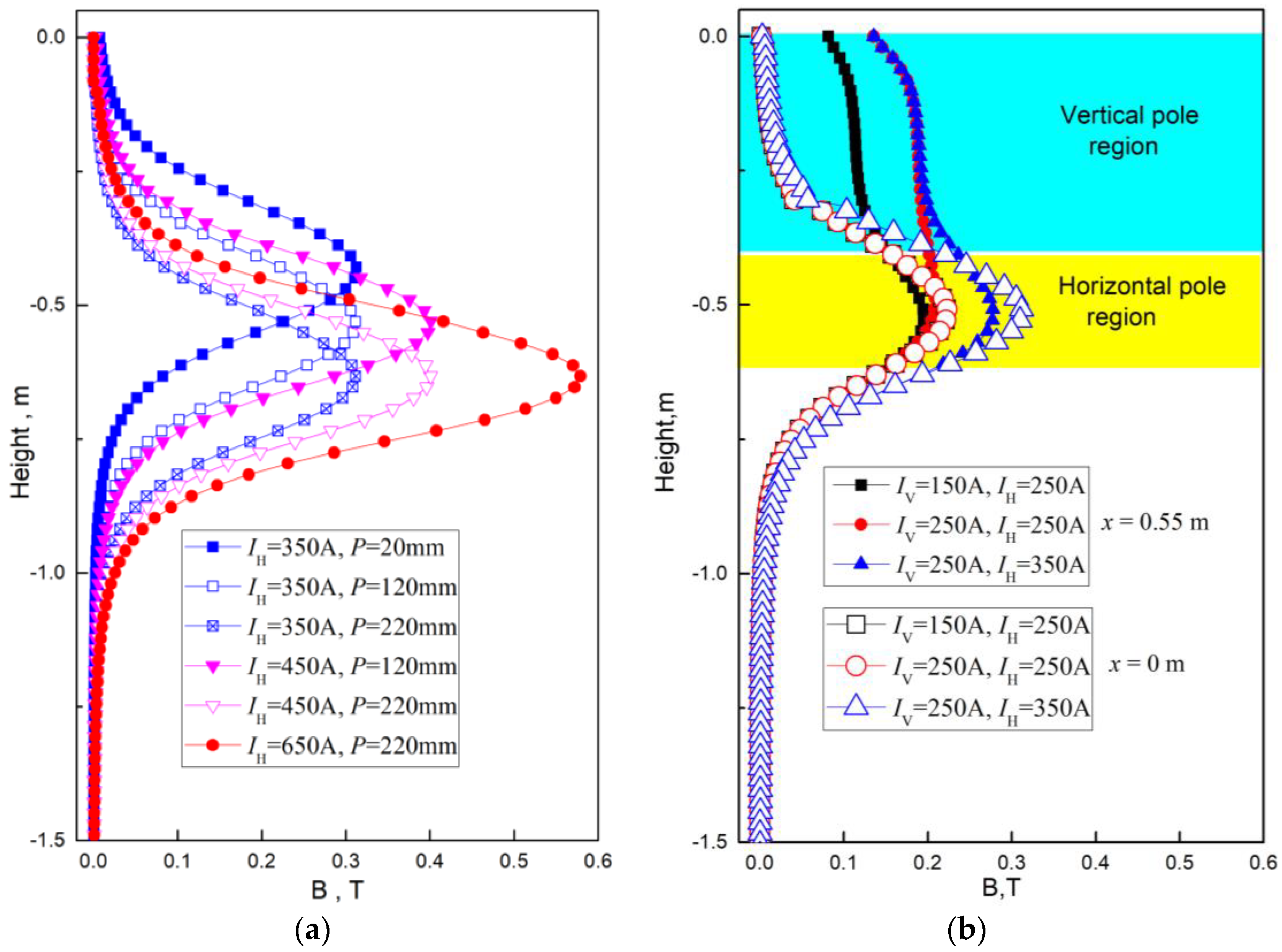
3.1. Distribution of Electromagnetic Field

Figure 5a,b shows the distribution of the magnetic induction intensity in the fluid region with application of the EMBr ruler and FAC-EMBr, respectively. The same input currents value (IH = 350 A) of the horizontal coil is selected for two type of EMBr, and the casting speed VC = 1.8 m/min. For the EMBr ruler, the horizontal magnetic pole position P = 120 mm. The same distance of P = 120 mm is selected for the FAC-EMBr, and the current intensity is IV = 250 A.
It can be seen from Figure 5a, in the case where the EMBr ruler is applied, the magnetic field is mainly distributed in the region where the horizontal magnetic pole is covered, and the magnetic induction intensity is almost zero in the meniscus region and at the outlet. However, in the case where the FAC-EMBr is applied, not only under the SEN region but, also, in the upper roll and meniscus regions, the steady magnetic field with uniform distribution can be formed. Therefore, the control of the velocity in the meniscus region and the level fluctuation can be realized.
Figure 6a,b shows the magnetic induction intensity distribution along the mold height direction in the thickness center plane of the mold under different coil current intensities with the EMBr ruler and FAC-EMBr. It can be seen from the Figure 6a, in the case where the EMBr ruler is applied, the maximum magnetic induction intensity is formed at the height center line of the horizontal magnetic pole and increased with the current intensity. The position of the maximum value of the magnetic induction intensity changes with the moving of the horizontal magnetic pole position P.
As the FAC-EMBr is applied, the distribution of the magnetic induction intensity along line x = 0 and line x = 0.55 in the thickness center plane (z = 0) are shown in Figure 6b. Along the line x = 0, as the increase of the current intensity, the distribution law of the magnetic induction intensity is the same as the EMBr ruler, which forms a peak value at the height center of the horizontal magnetic pole. However, compared with the EMBr ruler, the magnetic induction intensity is significantly increased along the line x = 0.55, and the distribution of the magnetic induction intensity becomes more uniform.
Figure 7a,b shows the vector distribution of the induced current at the thickness center plane (z = 0) under the two EMBr with the same current intensity (IH = 350 A). The input current value IV = 250 A. It can be seen from the Figure 7 that the vector magnitude and distribution of the induced current under the SEN are very similar as the EMBr ruler and FAC-EMBr are applied, which are distributed in the impact area of molten steel jet flow on both sides of the SEN port. This is mainly due to the horizontal magnetic pole position, and the current intensity for the EMBr ruler and FAC-EMBr are the same. However, with FAC-EMBr applied, strong induced currents are also formed in the upper roll and meniscus regions of mold, which is conducive to suppressing the velocity in the upper roll and meniscus regions and to stabilize the level fluctuation.
Figure 8a,b shows the distribution of Lorentz force F at the thickness center plane of the mold under the same operating parameters as EMBr ruler and FAC-EMBr were applied. It can be clearly seen that, in the case where the EMBr ruler is applied, the Lorentz force F is mainly formed in the jet impact region and the downwards roll-flow region, while the Lorentz force in the upper roll and meniscus regions are very small and even can be ignored. However, the Lorentz force in the upper roll and meniscus regions increase significantly after the FAC-EMBr is applied.

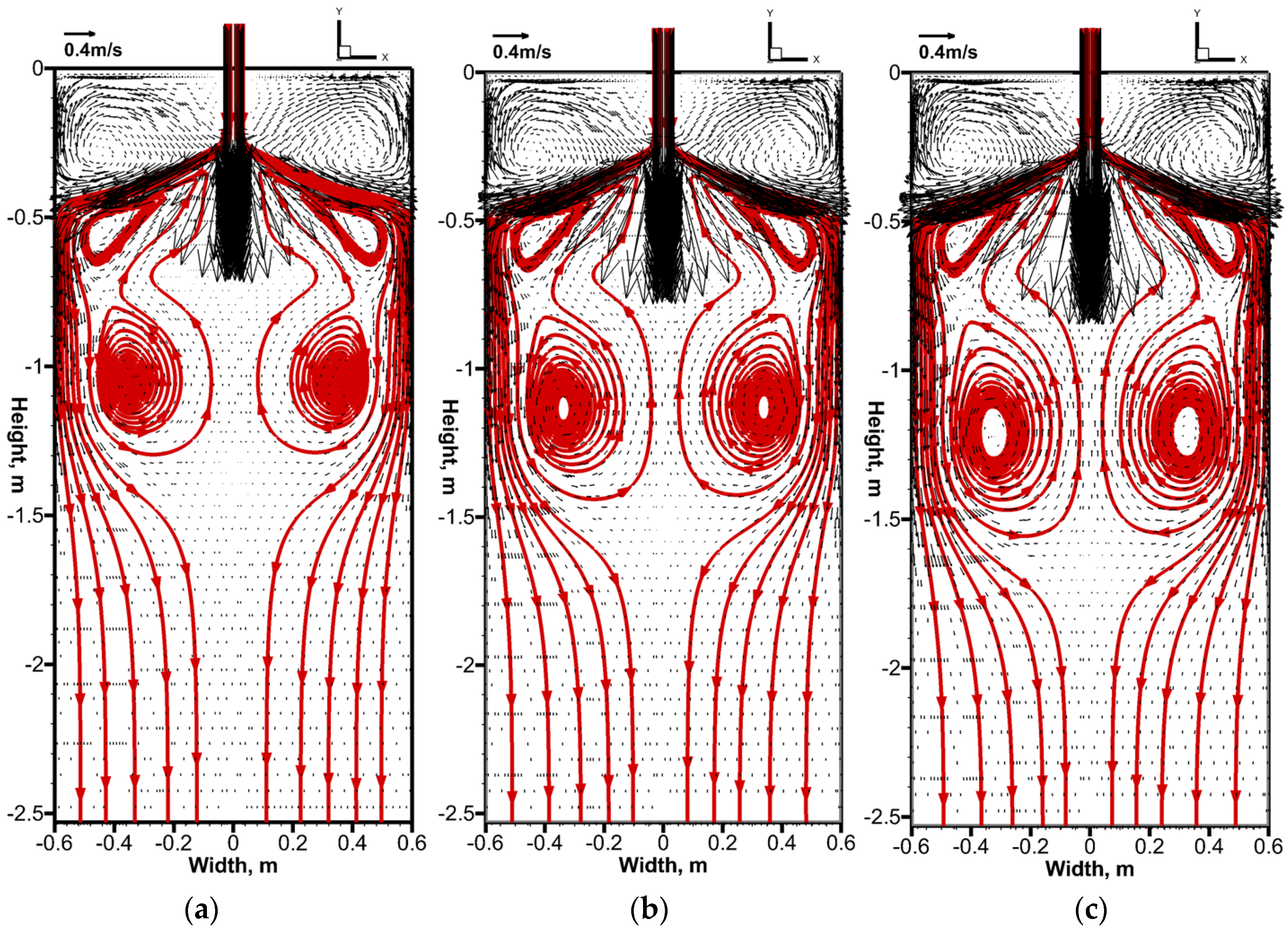
3.2. Influence of EMBr Ruler and FAC-EMBr on the Molten Steel Flow Field

Figure 9 and Figure 10 show the molten steel flow field and the streamline in the downwards roll-flow region at the thickness center plane (z = 0) under the effects of the EMBr ruler and FAC-EMBr with different casting speed conditions, respectively. As the EMBr ruler is applied, the horizontal magnetic pole position is P = 120 mm. The current intensity for the EMBr ruler and FAC-EMBr are IV = 250 A and IH = 350 A. It can be found from Figure 9 and Figure 10 that the flow pattern of molten steel is similar in the downwards roll-flow region when the EMBr ruler and FAC-EMBr are applied, and the center of the vortex moves downward as the casting speed is increased. This is due to the fact that the EMBr ruler and FAC-EMBr have the same horizontal magnetic pole position and similar magnetic induction intensity, so the braking effects of the EMBr ruler and FAC-EMBr on the downwards roll flow are similar. However, it can also be seen from Figure 9 and Figure 10 that the velocity in the upper roll region changes significantly as different EMBr are applied. When the EMBr is applied, the velocity increases obviously with the increase of the casting speed, especially near the meniscus region. However, when the FAC-EMBr was added, the molten steel velocity decreased significantly at the same casting speed. This is mainly because of the magnetic field generated by the vertical magnetic pole of the FAC-EMBr, which brakes the molten steel flow at the upper roll region and near the meniscus region for the second time (the first brake effect comes from the horizontal magnetic pole) and reduces the velocity of the molten steel. Due to the restriction by the interaction region of the horizontal magnetic pole, the application of the EMBr ruler cannot effectively restrain the flow in the upper roll region and near the meniscus region. Therefore, at the same casting speed, the molten steel velocity under the effect of the EMBr ruler is larger than that of the FAC-EMBr.
The contours of the turbulent kinetic energy near the NF of the mold (x = 0.595) on the effects of the EMBr ruler and FAC-EMBr are shown in Figure 11. It can be seen that the maximum value of the turbulent kinetic energy appears in the jet impact region. The distributions of the turbulent kinetic energy of molten steel below the impact point are similar for the applications of the EMBr ruler and FAC-EMBr. With application of the EMBr ruler, the turbulent kinetic energy below the meniscus region increases with the increasing of the casting speed. As the FAC-EMBr is applied, the turbulent kinetic energy does not change significantly at the same condition of the casting speed. This is mainly due to the application of the vertical magnetic pole to brake the velocity of the upper roll and weaken the impact of the upper roll on the meniscus. The reduction of the turbulent kinetic energy at the meniscus is beneficial to stabilize the level fluctuation and decrease the possibility of slag entrapment.
In order to further illustrate the influence of different magnetic fields on the molten steel flow at the steel/slag interface (y = −0.03), Figure 12 and Figure 13 show the velocity vector distribution and contours of the molten steel with applications of the EMBr ruler and FAC-EMBr, respectively. It can be seen from Figure 12 that, under the effects of the EMBr ruler, with an increase of the casting speed, the molten steel velocity at the steel/slag interface, especially at the position close to the NF of the mold, increases significantly. It is mainly due to the fact that the molten steel flow in the meniscus region is not restrained by the horizontal magnetic field. However, as the FAC-EMBr is applied, the molten steel velocity at the steel/slag interface is significantly reduced under the same casting speed conditions. Excessive flow velocity at the steel/slag interface easily forms “slag eye”, which leads to secondary oxidation of the liquid steel and is not conducive to improvement of the slab quality.
Figure 14 shows the effects of the EMBr ruler on the velocity distribution of molten steel in plane z = 0 m, plane y = −0.03 m, and the distribution of the surface velocity. It can be seen from Figure 12 and Figure 14 that the maximum velocity appears at the position about 0.46 m away from the nozzle, and the results are consistent. In addition, it also can be found from Figure 12, Figure 13 and Figure 14 that, overall, the surface velocity is very close to 0.1 m/s or even less. It is because the definition of plane y = −0.03 m is the interface of molten steel and liquid slag at a flow time t = 0 s. With the increase of the casting speed and flow time, the position of the steel/slag interface will change. It can be seen from Figure 14 that the position of the cut plane y = −0.03 m is mostly located in the liquid slag area, so the speed is small (because the viscosity of the slag is much larger than that of molten steel).

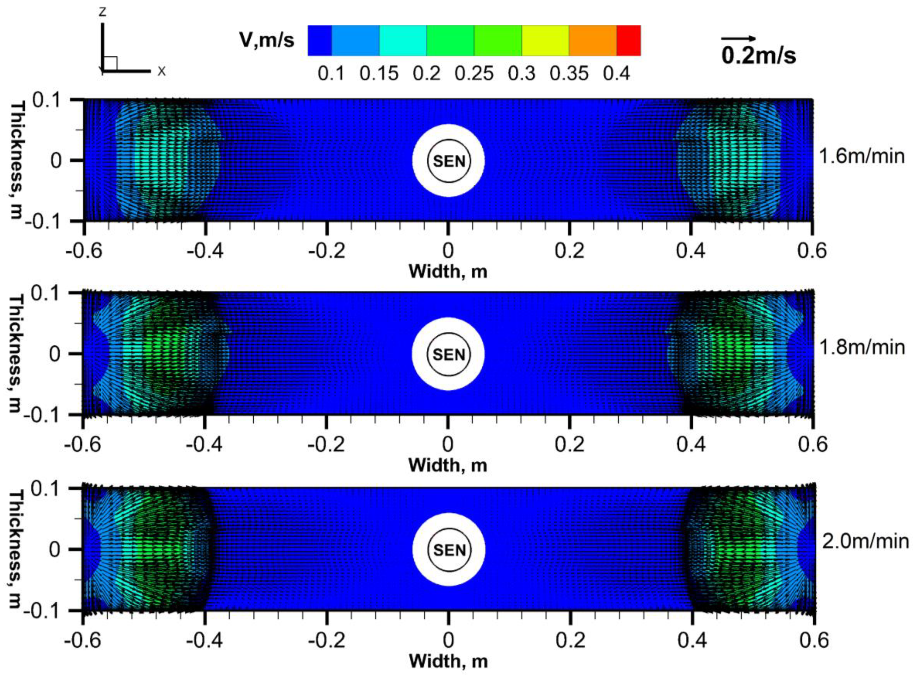
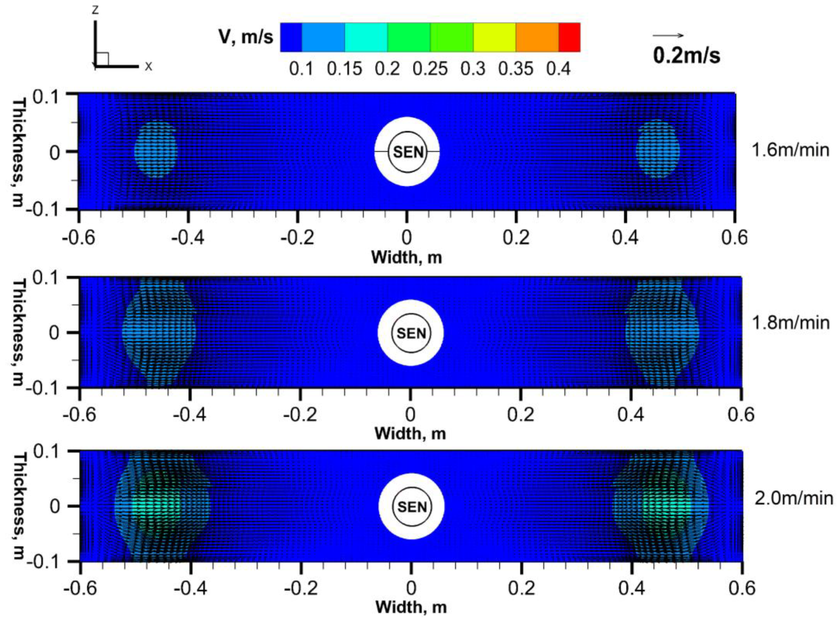
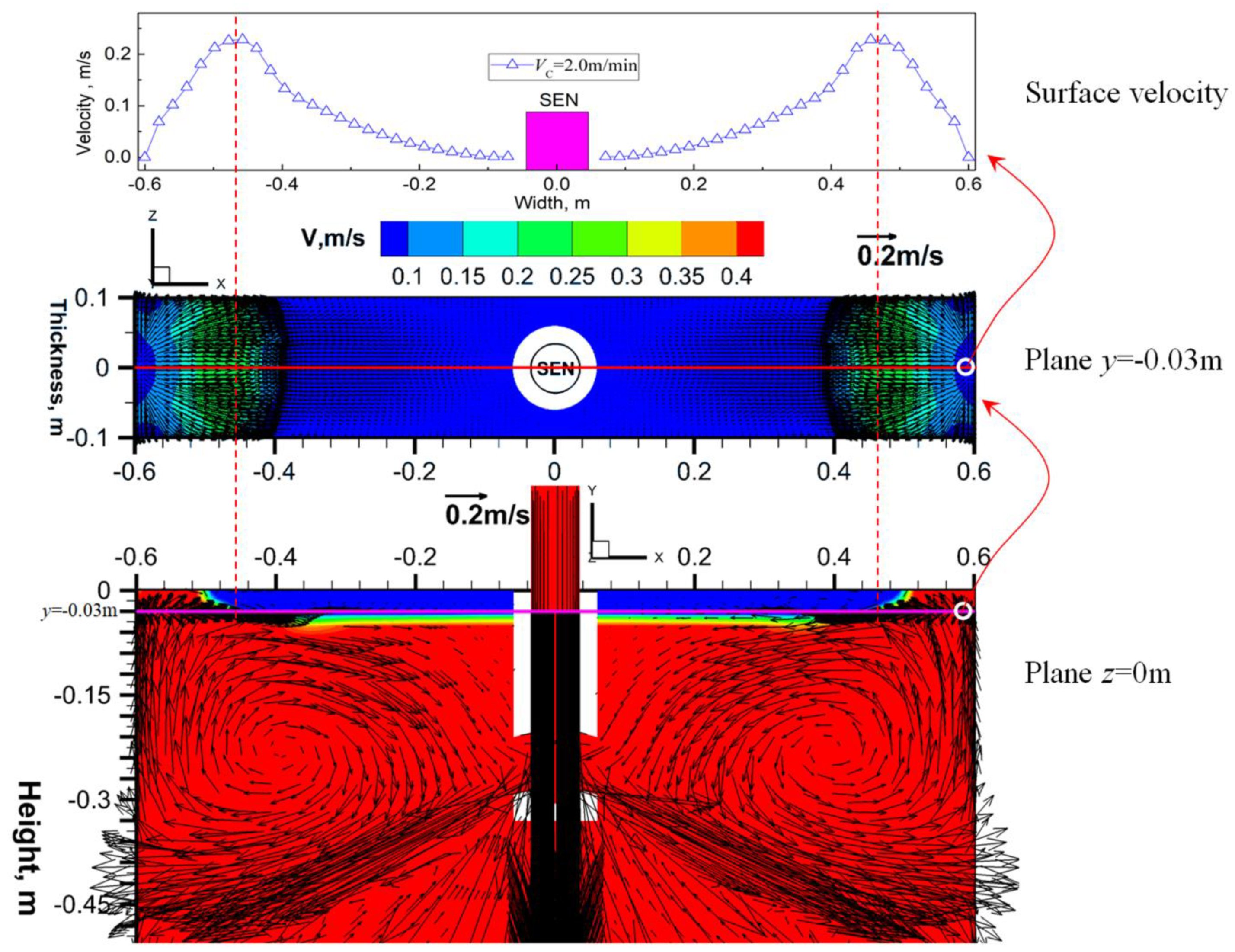
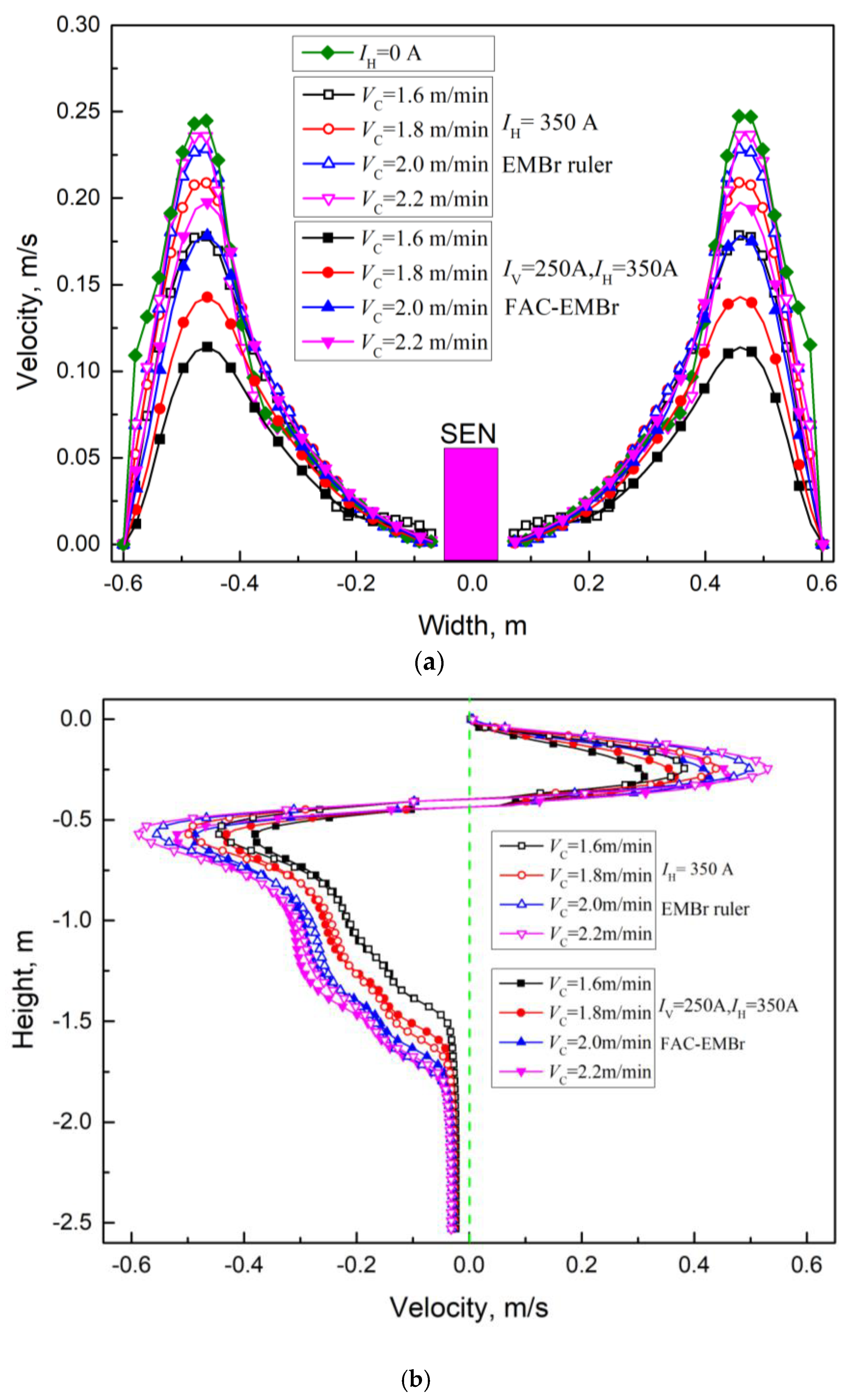
3.3. Effects of the EMBr Ruler and FAC-EMBr on the Flow Velocity

Figure 15a,b show the influence of the casting speed on the surface velocity (line y = −0.03) and the vertical velocity (line x = 0.595) of molten steel as the EMBr ruler and FAC-EMBr are applied, respectively.
For the EMBr ruler, the current intensity of the horizontal pole is IH = 350 A. For the FAC-EMBr, the current intensity of the horizontal pole is IH = 350 A, and IV = 250 A is selected for the vertical magnetic pole. It can be seen that, as the EMBr ruler is applied, the surface velocity and the vertical velocity in the upper roll and downwards roll-flow regions are increased with the increasing of the casting speed. The maximum surface velocity increases from 0.18 m/s to 0.24 m/s as the casting speed increases from 1.6 m/min to 2.2 m/min. Additionally, the maximum vertical velocity increases from 0.37 m/s to 0.51 m/s and increases from 0.43 m/s to 0.57 m/sin the upper roll and downwards roll-flow regions, respectively. As the FAC-EMBr is applied, the maximum surface velocity increases from 0.11 m/s to 0.20 m/s while the casting speed increases from 1.6 m/min to 2.2 m/min (increases from 0.22 m/s to 0.32 m/s as the EMBr is not applied). The maximum vertical velocity in the upper roll region increases from 0.31 m/s to 0.46 m/s and that increases from 0.38 m/s to 0.52 m/s in the downwards roll-flow region.
It also can be found from Figure 15a,b that, with the same casting speed, the application of the FAC-EMBr is more beneficial to depress the molten steel velocity in the upper roll region and meniscus region and then stabilize the level fluctuation.

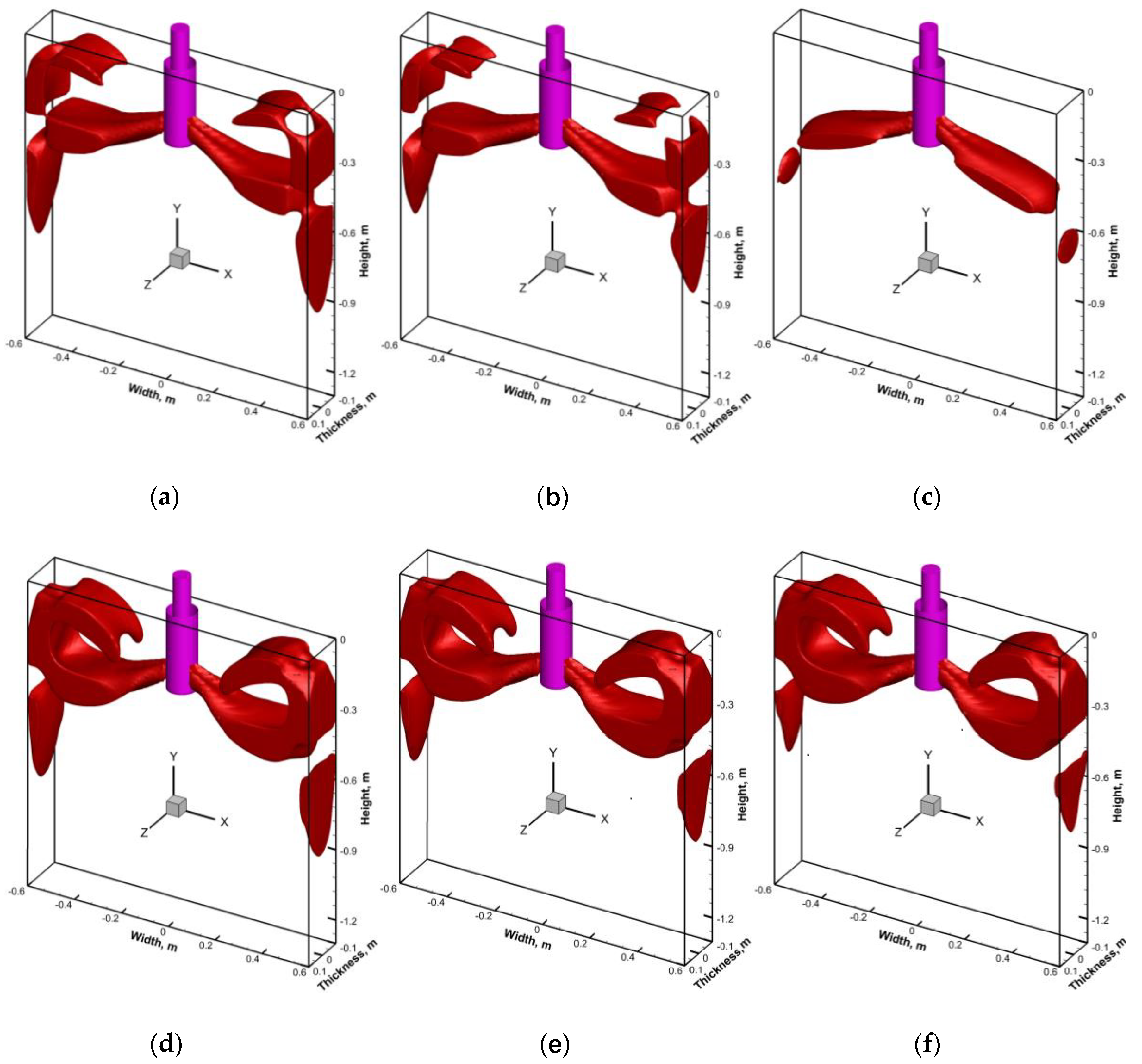
3.4. Influence of the EMBr Ruler and FAC-EMBr on the Jet Flow

Figure 16a–f shows the influence of the EMBr ruler on the molten steel velocity under the conditions of the different current intensity (IH) and different horizontal magnetic pole position (P), respectively (red color in the figure represents the isosurface of the molten steel velocity; VSteel = 0.3 m/s). The casting speed is VC = 1.8 m/min. It can be seen from Figure 16a,b that, as the current intensity increases from 350 A to 450 A, the molten steel velocity in the upper roll and downwards roll-flow regions are all slightly decreased, but the velocity are still above 0.3 m/s. At this time, if the magnetic pole position is moved up 100 mm to the case1 position (Figure 16c), where the horizontal pole can cover the three key regions, it is found that the molten steel velocity the in upper roll and downwards roll-flow regions are all significantly reduced, and the molten steel velocities are all less than 0.3 m/s.
However, when the horizontal magnetic pole is moved to the position ofcase3 (Figure 16d), in the horizontal magnetic field, it is difficult to suppress the velocity in the upper roll and meniscus regions due to the long distance between the horizontal magnetic pole and SEN, and the velocity in the upper roll and meniscus regions all exceed 0.3 m/s. In this case, if the current intensity continues to increase, only the velocity of the downwards roll flow can be continuously decreased, while the velocity of the upper roll will no longer be suppressed (Figure 16e,f).In addition, Figure 16 also indicates that the molten steel flow can be effectively controlled by the EMBr ruler with a reasonable horizontal magnetic pole position. Recently, Dennis Schurmannet al. studied the effects of different magnetic pole positions on the behavior of the molten steel flow under the effects of the EMBr ruler by using the physical experimental method and obtained similar results with this paper: for a lower brake position and a higher magnetic induction intensity, the intensity and velocity of the upper roll were all increased [24].
Figure 17a–f shows the molten steel velocity under the conditions of different current intensities (IH and IV) in the case where the FAC-EMBr is applied, respectively (red color in the figure represents the isosurface of the molten steel velocity; VSteel = 0.3 m/s). The casting speed is VC = 1.8 m/min. It can be found from Figure 17a–c that, as the current intensity IV keeps a constant value, the molten steel velocity in the downwards roll-flow region significantly decreases with the increase of IH (which also reflects the advantages of the EMBr ruler). When the current intensity IV = 250 A and IH gradually increased from 250 A to 350 A (Figure 17e,f), the molten steel velocities in the upper roll and downwards roll-flow regions are significantly reduced, and the velocity in the meniscus region is reduced to less than 0.3 m/s. In the case of IV = IH =350 A, it can be seen that the brake effect of the FAC-EMBr is almost the same as that of the EMBr ruler with the optimal magnetic pole position.
Therefore, with application of the FAC-EMBr, the molten steel velocity in the downwards roll-flow region can be firstly restrained by adjusting the input current of IH and, then, by adjusting the current intensity of IV to brake the molten steel flow in the upper roll and meniscus regions, which can achieve a more ideal flow state. Since the input current in the vertical coil and the horizontal coil can be adjusted independently, the variation of the SEN depth DSEN and port angle θP have little influence on the brake effects of the FAC-EMBr.

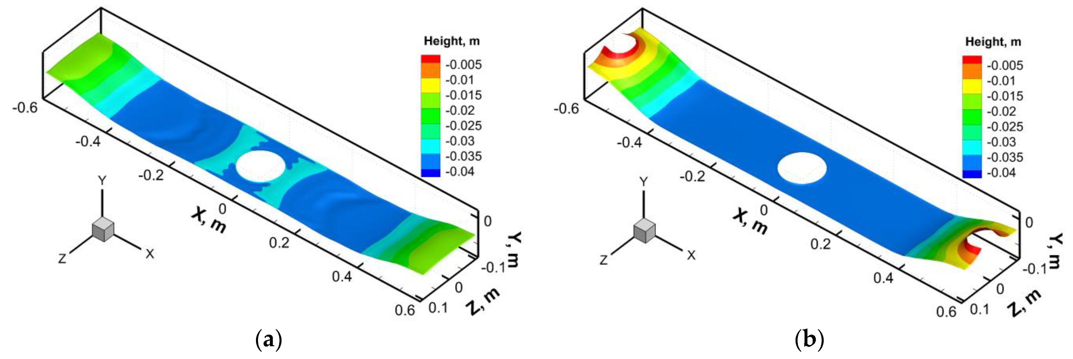
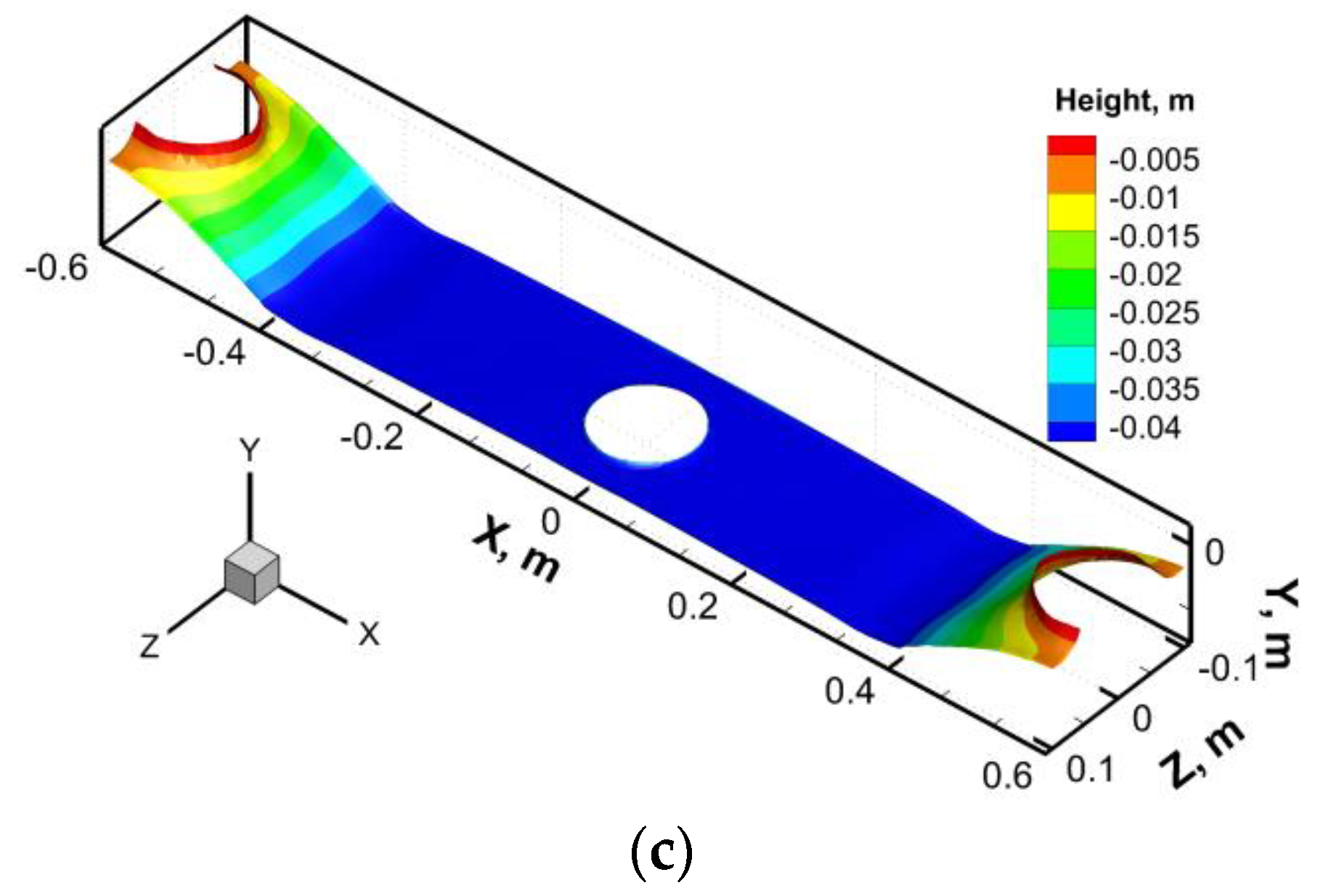
3.5. Effects of the EMBr Ruler and FAC-EMBr on the Level Fluctuation

Figure 18 and Figure 19 show the influence of the casting speed on the level fluctuation under the effects of the EMBr ruler and FAC-EMBr, respectively. The current intensity IH for the EMBr ruler is 350 A, and the horizontal magnetic pole position is P =120 mm. As can be seen from Figure 18, while the casting speed increases from 1.6 m/min to 2.2 m/min, the meniscus wave height near the NF of the mold gradually increases from 20.3 mm to 45 mm. As the casting speed reaches 2.0 m/min, the liquid slag layer near the meniscus is pushed away by the upper roll, and the molten steel is exposed to the air. As the casting speed continues to increase, this phenomenon of the molten steel exposed to the air becomes worse. This is due to the limitation of the horizontal magnetic field of the EMBr ruler, which cannot effectively control the upper roll flow, so with the increase of the casting speed, the molten steel velocity in the upper roll region increases significantly, and the meniscus wave height increases gradually.
Figure 19 shows that, with application of the FAC-EMBr, the meniscus wave height increases from 8.5 mm to 21.1 mm as the casting speed increases from 1.6 m/min to 2.2 m/min. It also can be found that the liquid slag layer near the meniscus is not washed away by the upper roll, as the casting speed is 2.2 m/min. This is mainly due to the application of the vertical magnetic pole, which effectively suppress the molten steel velocity in the upper roll region and reduces the impact strength of the upper roll flow, so that the steel/slag interface tends to be stable, and the meniscus wave height is less than that of the EMBr ruler under the same conditions. It can be concluded that the application of the FAC-EMBr is more beneficial to control the molten steel flow in the upper and lower regions with the condition of a high casting speed and then improve the quality of the continuous casting slab.

4. Conclusions

In this paper, the numerical simulations were conducted to study the behavior of the molten steel flow and the steel/slag interface fluctuations in the EMBr ruler and FAC-EMBr molds. The electromagnetic characteristics, molten steel flow characteristics, and the control effects of the different EMBr forms on the steel/slag interface fluctuations were compared and analyzed. The main conclusions were as follows:
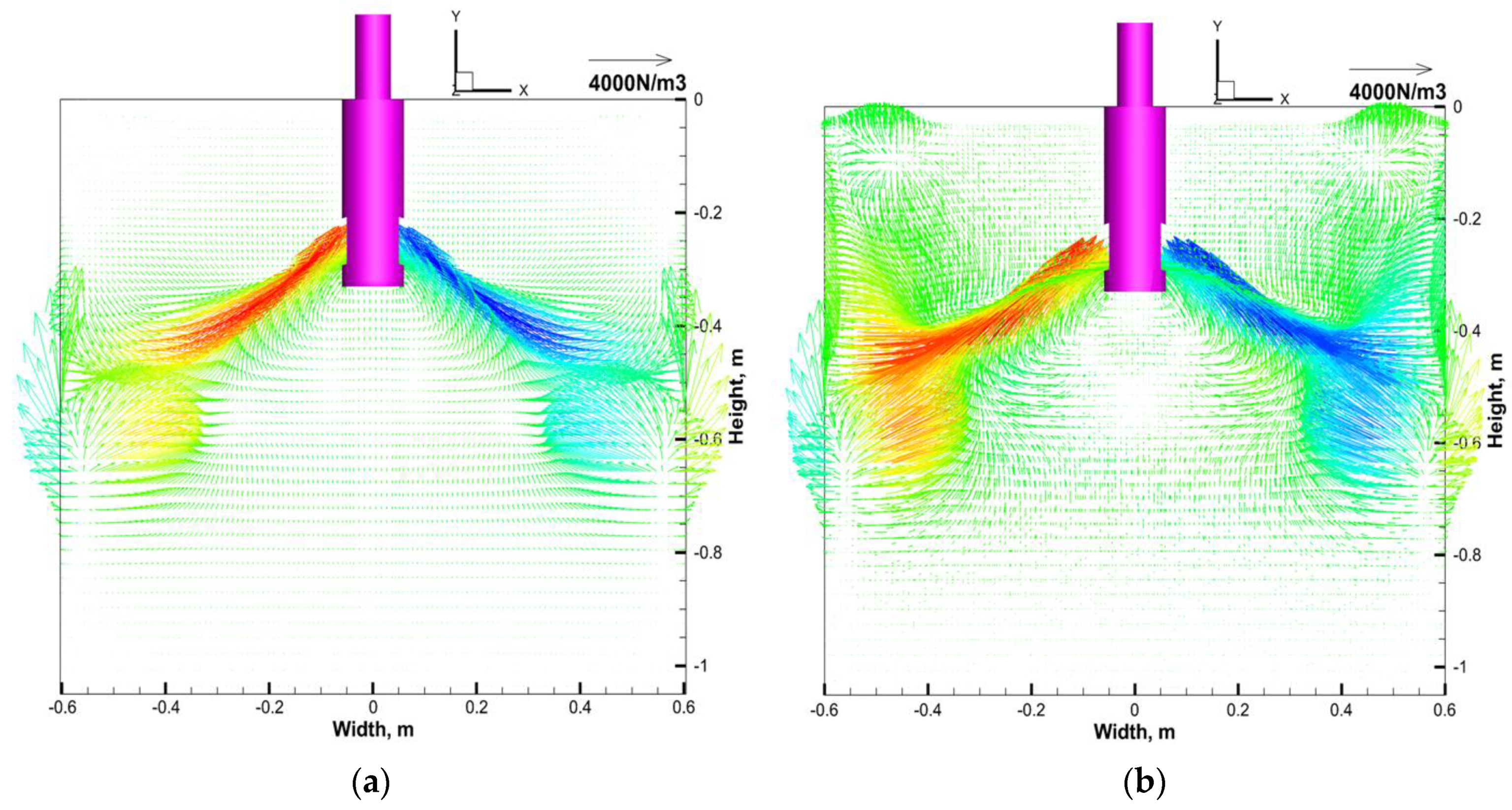
  • The electromagnetic field of the EMBr ruler was mainly distributed in the horizontal magnetic pole area. The magnetic induction intensity in the upper roll and meniscus regions was very small. The Lorentz force was mainly distributed in the molten steel jet impact region and the downwards roll-flow region near the jet impingement point on both sides of the SEN. The electromagnetic force was very small in the upper roll and meniscus regions.
  • With the application of the FAC-EMBr, the steady magnetic field was formed in the horizontal magnetic pole region and the upper roll and meniscus regions, and a strong Lorentz force could be formed in these regions, so the velocity of the molten steel in these regions could be significantly reduced.
  • As the distance between the SEN and the horizontal magnetic pole was far (case 2 and case 3), the application of the EMBr ruler could not effectively brake the upper roll flow and reduce the meniscus wave height.
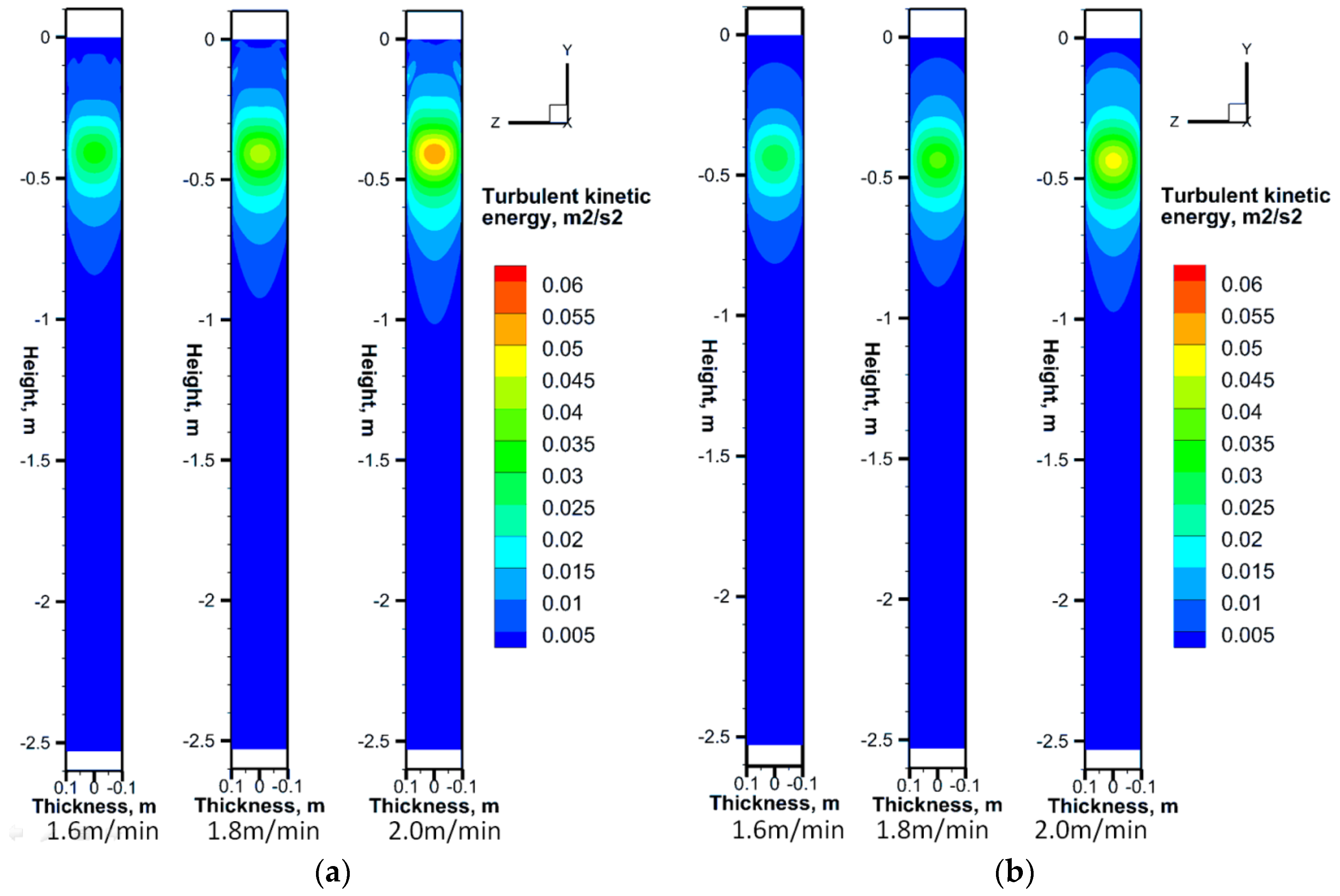
  • For the FAC-EMBr, increasing the current intensity IV could significantly reduce the molten steel velocity in the upper roll and meniscus regions, decrease the meniscus wave height, and stabilize the level fluctuations; increasing the current intensity IH could effectively decrease the impingement of the jet and the molten steel velocity, which was beneficial to the formation of the piston flow.
  • The FAC-EMBr had independent adjustable characteristics, which made it possible to control the molten steel flow in the key areas comprehensively and flexibly and achieve a more appropriate flow state in the mold.

Author Contributions

Conceptualization, Z.L. and L.Z.; investigation, Z.L., D.M., and Y.B.; writing—original draft preparation, Z.L. and L.Z.; writing—review and editing, Z.L. and L.Z.; project administration, Z.L.; and funding acquisition, Z.L. All authors have read and agreed to the published version of the manuscript.

Funding

This research was funded by the National Natural Science Foundation of China, grant number 51804154, and the College and University Scientific Research Projects in Liaoning Province, grant number L2020023.

Acknowledgments

The authors thank the referees for their work, which greatly contributed to this article.

Conflicts of Interest

The authors declare no conflict of interest.

References

  1. Calderón-Ramos, I.; Morales, R.D.; Servín-Castañeda, R.; Pérez-Alvarado, A.; García-Hernández, S.; Barreto, J.D.J.; Arreola-Villa, S.A. Modeling study of turbulent flow in a continuous casting slab mold comparing three ports SEN designs. ISIJ Int. 2019, 59, 76–85. [Google Scholar] [CrossRef] [Green Version]
  2. Yang, H.; Vanka, S.P.; Thomas, B.G. Mathematical modeling of multiphase flow in steel continuous casting. ISIJ Int. 2019, 59, 956–972. [Google Scholar] [CrossRef] [Green Version]
  3. Li, B.K. Study on turbulent flow field of liquid steel and its electromagnetic control in continuous casting mold at high casting speed. Iron Steel 2005, 40, 33–36. [Google Scholar]
  4. Singh, V.; Das, S.K. Mathematical model and plant investigation to characterize effect of casting speed on thermal and solidification behavior of an industrial slab caster. ISIJ Int. 2018, 58, 2308–2317. [Google Scholar] [CrossRef] [Green Version]
  5. Wang, Y.F.; Zhang, L.F. Fluid flow-related transport phenomena in steel slab continuous casting strands under electromagnetic brake. Metall. Mater. Trans. B 2011, 42, 1319–1351. [Google Scholar] [CrossRef]
  6. Cho, S.-M.; Thomas, B.G. Electromagnetic forces in continuous casting of steel slabs. Metals 2019, 9, 471. [Google Scholar] [CrossRef] [Green Version]
  7. Thomas, B.G. Continuous casting of steel. In Modeling for Casting and Solidification Processing; Kuang-Oscar, Y., Ed.; Marcel Dekker: New York, NY, USA, 2001; Chapter 15; pp. 499–540. [Google Scholar]
  8. Jin, K.; Vanka, S.P.; Thomas, B.G. Large eddy simulations of the effects of EMBr and SEN submergence depth on turbulent flow in the mold region of a steel caster. Metall. Mater. Trans. B 2017, 48, 162–178. [Google Scholar] [CrossRef]
  9. Thomas, B.G.; Yuan, Q.; Mahmood, S. Transport and entrapment of particles in steel continuous casting. Metall. Mater. Trans. B 2014, 45, 22–35. [Google Scholar] [CrossRef]
  10. Cho, S.-M.; Thomas, B.G.; Kim, S.-H. Bubble behavior and size distributions in stopper-rod nozzle and mold during continuous casting of steel slabs. ISIJ Int. 2018, 58, 1443–1452. [Google Scholar] [CrossRef] [Green Version]
  11. Miki, Y.; Takeuchi, S. Internal defects of continuous casting slabs caused by asymmetric unbalanced steel flow in mold. ISIJ Int. 2003, 43, 1548–1555. [Google Scholar] [CrossRef] [Green Version]
  12. Choi, S.L.; Ryu, K.J.; Park, H.S. Numerical simulation on the effect of an electromagnetic brake to continuous thin slab casting. Met. Mater. Int. 2002, 18, 527–533. [Google Scholar]
  13. Sarkar, S.; Singh, V.; Ajmani, S.K.; Ranjan, R.; Rajasekar, K. Effect of double ruler magnetic field in controlling meniscus flow and turbulence intensity distribution in continuous slab casting mold. ISIJ Int. 2016, 56, 2181–2190. [Google Scholar] [CrossRef] [Green Version]
  14. Hwang, Y.-S.; Cha, P.-R.; Nam, H.-S.; Moon, K.-H.; Yoon, Y.-K. Numerical analysis of on the fluid flow and the influences meniscus shape of operational parameters in slab caster with EMBR. ISIJ Int. 1997, 37, 659–667. [Google Scholar] [CrossRef]
  15. Idogawa, A.; Sugizawa, M.; Takeuchi, S.; Sorimachi, K.; Fujii, T. Control of molten steel flow in continuous casting mold by two static magnetic fields imposed on whole width. Mat. Sci. Eng. A Struct. 1993, 173, 293–297. [Google Scholar] [CrossRef]
  16. Wang, Y.F.; Dong, A.P.; Zhang, L.F. Effect of slide gate and EMBr on the transport of inclusions and bubbles in slab continuous casting strands. Steel Res.Int. 2011, 82, 428–439. [Google Scholar] [CrossRef]
  17. Jin, K.; Vanka, S.P.; Thomas, B.G. Large eddy simulations of electromagnetic braking effects on argon bubble transport and capture in a steel continuous casting mold. Metall. Mater. Trans. B 2018, 49, 1360–1377. [Google Scholar] [CrossRef]
  18. Yu, H.Q.; Zhu, M.Y. Numerical simulation of the effects of electromagnetic brake and argon gas injection on the three-dimensional multiphase flow and heat transfer in slab continuous casting mold. ISIJ Int. 2008, 48, 548–591. [Google Scholar] [CrossRef] [Green Version]
  19. Harada, H.; Toh, T.; Ishii, T.; Kaneko, K.; Takeuchi, E. Effect of magnetic field conditions on the electromagnetic braking efficiency. ISIJ Int. 2001, 41, 1236–1244. [Google Scholar] [CrossRef]
  20. Li, Z.; Zhang, L.T.; Ma, D.Z.; Wang, E.G. Numerical simulation on flow characteristic of molten steel in the mold with freestanding adjustable combination electromagnetic brake. Metall. Mater. Trans. B 2020, 51, 2609–2627. [Google Scholar] [CrossRef]
  21. Yu, H.Q.; Zhu, M.Y.; Wang, J. Interfacial fluctuation behavior of steel/slag in medium-thin slab continuous casting mold with argon gas injection. J. Iron Steel Res. Int. 2010, 17, 5–11. [Google Scholar] [CrossRef]
  22. Li, Z.; Wang, E.G.; Xu, Y. Behavior of molten steel flow in continuous casting mold with different static magnetic field configurations. J. Iron Steel Res. Int. 2018, 25, 366–377. [Google Scholar] [CrossRef]
  23. Li, Z.; Wang, E.G.; Zhang, L.T.; Xu, Y.; Deng, A.Y. Influence of vertical electromagnetic brake on the steel/slag interface behavior in a slab mold. Metall. Mater. Trans. B 2017, 48, 2389–2402. [Google Scholar] [CrossRef]
  24. Schurmann, D.; Glavinić, I.; Willers, B.; Timmel, K.; Eckert, S. Impact of the electromagnetic brake position on the flow structure in a slab continuous casting mold: An experimental parameter study. Metall. Mater. Trans. B 2020, 51, 61–78. [Google Scholar] [CrossRef]
Figure 1. Schematic diagram of the freestanding adjustable combination electromagnetic brake (FAC-EMBr) configuration. SEN: submerged entry nozzle.
Processes 08 01620 g001
Figure 2. Geometric model and dimensions of the fluid region. (a) EMBr ruler, (b) FAC-EMBr, and(c) the dimensions of the SEN and ports. NF: narrow face, WF: wide face.
Processes 08 01620 g002
Figure 3. Computational domain of the fluid and grid. (a) the computational domain of the fluid, (b) the mesh of the domain.
Processes 08 01620 g003
Figure 4. Validation of the magnetic field and level fluctuation in thevertical electromagnetic braking mold. (a) distribution of magnetic induction intensity, (b) the level fluctuation under the effect of different current.
Processes 08 01620 g004aProcesses 08 01620 g004b
Figure 5. Distribution of the magnetic induction intensity in the fluid region with different electromagnetic brakes: (a) EMBr ruler and (b) FAC-EMBr.
Processes 08 01620 g005
Figure 6. Distribution of the magnetic induction intensity along the height direction: (a) EMBr ruler and (b) FAC-EMBr. IV and IH: the current of the vertical and horizontal magnetic poles.
Processes 08 01620 g006
Figure 7. The distribution of the induced current density with the condition of VC = 1.8 m/min: (a) EMBr ruler: P = 120 mm, IH = 350 A and (b) FAC-EMBr: P = 120 mm, IH = 350 A, IV = 250 A.
Processes 08 01620 g007
Figure 8. Distribution of the Lorentz force F on the condition of VC = 1.8 m/min: (a) EMBr ruler: P = 120 mm, IH = 350 A and (b) FAC-EMBr: P = 120 mm, IH = 350 A, IV = 250 A.
Processes 08 01620 g008
Figure 9. The flow field and the streamline in the downwards roll-flow region at the thickness center plane (z = 0) with the EMBr ruler: (a) VC = 1.6 m/min, (b) VC = 1.8 m/min, and (c) VC = 2.0 m/min.
Processes 08 01620 g009
Figure 10. The flow field and the streamline in the downwards roll-flow region at the thickness center plane (z = 0) with the FAC-EMBr: (a) VC = 1.6 m/min, (b) VC = 1.8 m/min, and (c) VC = 2.0 m/min.
Processes 08 01620 g010
Figure 11. The contour of the turbulent kinetic energy near the NF of mold (x = 0.595) with theEMBr ruler and FAC-EMBr. (a) EMBr ruler and (b) FAC-EMBr.
Processes 08 01620 g011
Figure 12. Velocity vector distribution and contours of molten steel at the steel/slag interface with the EMBr ruler.
Processes 08 01620 g012
Figure 13. Velocity vector distribution and contours of molten steel at the steel/slag interface with the FAC-EMBr.
Processes 08 01620 g013
Figure 14. Effects of the EMBr ruler on the velocity distribution of molten steel.
Processes 08 01620 g014
Figure 15. Distributionof the surface and vertical velocitieson the effects of the EMBr ruler and FAC-EMBr. (a) Surface velocity. (b) Vertical velocity.
Processes 08 01620 g015
Figure 16. Molten steel velocity in the isosurface. (a) IH = 350 A and P = 120 mm, (b) IH = 450 A and P =120 mm, (c) IH = 350 A and P =20 mm, (d) IH = 350 A and P = 220 mm, (e) IH = 450 A and P = 220 mm, and (f) IH = 650 A and P = 220 mm.
Processes 08 01620 g016
Figure 17. Molten steel velocity in the isosurface. (a) IV = 150 A and IH = 150 A, (b) IV = 150 A and IH =250 A, (c) IV = 150 A and IH = 350 A, (d) IV = 250 A and IH = 250 A, (e) IV = 250 A and IH = 350 A, and (f) IV = 350 A and IH = 350 A.
Processes 08 01620 g017aProcesses 08 01620 g017b
Figure 18. Steel/slag interface profiles under the EMBr ruler with different casting speed. (a) VC = 1.6 m/min and IH =350 A, (b) VC = 1.8 m/min and IH = 350 A, and (c) VC = 2.0 m/min and IH = 350 A.
Processes 08 01620 g018aProcesses 08 01620 g018b
Figure 19. Steel/slag interface profiles under the FAC-EMBr with different casting speeds. (a) VC = 1.6 m/min, IV = 250 A, and IH = 350 A; (b) VC = 1.8 m/min, IV = 250 A, and IH = 350 A; (c) VC = 2.0 m/min, IV = 250 A, and IH = 350 A; and (d) VC = 2.2 m/min, IV = 250 A, and IH = 350 A.
Processes 08 01620 g019
Table 1. Physical properties of the molten steel (1600 °C) and liquid slag phases [21].
MaterialDensity ρ (kg m s−1)Dynamic Viscosity μ (kg m−1 s−1)Electrical Conductivity σ (S m−1)
Steel71000.0067.14 × 105
Slag27000.21 × 10−5
Table 2. Parameters used in the computational simulation.
VariablesValues
Current I(EMBr ruler), AIH = 350, 450, 650
Current I(FAC-EMBr), A(IV = 100, IH = 350), (IV = 150, IH = 350), (IV = 250, IH = 350), (IV = 350, IH = 350)
Pole position(EMBrruler)P, mm20, 120, 220
Immersion depth of SENDSEN, m0.18
Port angle of SEN θP, deg−15
Dimension of the SEN port, m0.065 × 0.083
Inner/outer diameter of the SEN, m0.07/0.12
Casting speed VC, m/min,1.6, 1.8, 2.0, 2.2
IV and IH: the current of the vertical and horizontal magnetic poles. FAC-EMBr: freestanding adjustable combination electromagnetic brake and SEN: submerged entry nozzle.
Publisher’s Note: MDPI stays neutral with regard to jurisdictional claims in published maps and institutional affiliations.

