1. Introduction
Rotating drum is one of the most common instruments used for granular mixing in various industries such as food processing, pharmaceuticals, ceramic, nuclear, and chemical industries [
1,
2,
3,
4,
5,
6]. This is due to its simple geometry and multiple applications such as mixing, segregation, drying, and coating. As a simple example, it is applied in the mixing salts, sugar and tomato paste to make tomato sauce in food industry. The fundamental phenomenon of granular mixing inside rotating drums is still not fully understood [
7,
8,
9,
10,
11], which makes it difficult to predict the practical process although a lot of research has been carried out on granular mixing in the last three decades [
12,
13]. Therefore, understanding the mixing phenomenon is important for both the engineering process as well as fundamental research in granular mechanics.
The particle flow in rotating drums displays complex dynamical behaviour, and exhibits different regimes under different conditions. The mixing of particles is influenced by various parameters such as the static and dynamic angle of repose, granular shape, size, density, poisons ratio, shear/young’s modulus, coefficient of restitution and filling fraction [
11,
14,
15,
16,
17,
18]. It is mathematically quantified with the help of a mixing index. The main mixing indices used in the past include the ones by Lacey (1954), Michaels and Puzinaukas (1954), Lineman (1961), Chudzikiewicz (1962), Rose and Robinson (1965), Valentin (1967) and Kramer (1968) [
13,
19]. The Lacey mixing index is one of the most widely used index for the mathematical quantification of the degree of granular mixing in rotating drums [
20]. It has been used to demonstrate and compare the mixing efficiency of mixing tools, e.g., rotating drums [
5,
9,
10,
13,
18,
19,
21,
22].
The particle flow regime in a rotating drum depends on the Froude number and drum filling degree [
23]. Many studies on mixing have been focused on the rolling regime of the granular flow where particles form a mixture mostly in the active surface region [
24,
25]. The study of Arntz et al. [
7] indicated that the segregation of particles is causally linked to the flow regime by a percolation mechanism. The later investigation has also been carried out to study the effect of end wall on mixing degrees in a short rotating drum with one side of the wall to be fixed and the other moving with the cylinder. Three different flow patterns were identified depending on the filling degree and rotational velocity [
26]. Flow patterns in such conditions suggest that the particles in the active region tend to move towards the rotating end wall and particles in the passive region tend to move along the stationary wall which leads to the decrease of mixing index [
26].
Many results have been achieved in the previous studies in terms of the effect of parameters on the particle mixing in rotating drums. It was indicated that particles density plays a major role in defining mixing index rather than the size and shape of the particles. An increase in the difference between the densities of two particles would lead to a reduction in mixing index [
11]. This is also true for the non-homogenous mixtures [
12]. Xiao et al. [
27] considered the ratio of the active region area to the whole bed area for a rotating drum. With the variation of the rotational speed and filling degree, they achieved different values of the area ratio and concluded that with the increase in rotational speed and reduction in filling degree, the time for mixing increases but the overall mixing index almost remains the same. Further, Liu et al. [
10] considered wet particles, and demonstrated that with the increase in the surface tension mixing rate of particles reduces as compared to the dry particles, and this effect increases with the increase in the number of particles and decreases with angular velocity. Jiang et al. [
4] conducted a micro-dynamics study of segregation and mixing of a bi-disperse system of two particle sizes in the rotating drum with baffles using the discrete element method (DEM). The results displayed that particle diffusion, convection, and size segregation all play substantial roles in the combining process while size segregation would be mainly controlled when the drum blender has a baffle, irrespective of its shape, and the level of colliding was higher when compared with an unbaffled drum mixer.
While many studies have been conducted to study the dynamics of mixing phenomenon for the rotating drum with the horizontal axis of rotation, little emphasis has been given to study the drums with an angle of inclination, particularly for batch operation of rotating drum reactors, e.g., for mixing processes. For rotating drum reactors in continuous operation mode, the effects of the reactor inclination have been tested in several studies [
28,
29,
30]. To our knowledge, there is not any study on the simulation of inclined rotating drums in batch mode. It is important to understand the mechanics of the particles inside inclined rotating drums for fundamental understanding, as well as for industrial engineering purposes, as such drums are widely used in industries.
In this study, the DEM was used to investigate the effect of the angle of inclination to the particle mixing in a rotating drum in batch mode. The method is a well-established one to study mixing phenomena in rotating drums [
31]. The major advantage of the DEM is that it can provide a large amount of data for the particles at each time step for various properties to provide an opportunity to conduct in-depth analysis. Four angles of inclination for the rotating drum ranging from 0° to 15° were considered, and some key properties related to particle mixing such as net mass flow rate, volumetric fill, area ratio, and Lacey mixing index were examined in detail in the present work.
3. Results and Discussion
For the horizontal rotating drum (α = 0°), the mixing pattern obtained in the present work is similar to that obtained in the previous simulation studies [
31]. Further, comparing the present simulation results with the experimental ones done by Alizadeh et al. [
4] shows that the two cases have a similar trend for the transverse velocity of the mixed binary-size particles along the central axis of the drum. The average transverse velocity is 0.00214 m/s for the simulation and 0.0022 m/s for the physical experiment. Kawaguchi et al. [
38] used an MRI measurement technique to study a tapered rotating drum, with an angle of inclination of nearly 5.6°. In their study, the size ratio of the particles is also 1:2, and the angular speed 30 rpm, same as those in the present work. Comparing the simulation results for the case of α = 5° (
Figure 2) with their results demonstrates a similar pattern: large particles are mostly located at the surface of the flow and near the wall of the drum. The results with the same trend in the DEM simulation and experiment validate the applicability of the DEM simulation model in the present study. In the following sections, some key properties related to particle mixing, including mass flow rate, volumetric fill, area ratio, and mixing index, will be considered in detail.
3.1. Net Mass Flow Rate
In an inclined rotating drum, particles tend to move towards the lower end of the drum, which is caused by the component of gravitational force acting on the particles in the axial direction of the drum. To quantify the particle flow along the axial direction of the drum, net mass flow rate is considered here.
The net mass flow rate at a section is the difference between mass leaving and entering the section per unit time. To conduct analysis, small slices of the drum with thickness of 15 mm and radius equivalent to that of the drum were created at the cross sections located at
La = 25, 425, and 825 mm (distance to the bottom of the drum). The net mass flow rate at a location is defined as the difference between mass leaving and entering the slice related to the location per unit time. As illustrated in
Figure 3, for all locations and inclined drums considered, the net mass flow rate increases with the time of simulation, peaks at
t = 0.5 s, and then decreases until a steady state is achieved. The generation of the peaks is due to the initial avalanche of the particle bed caused by the gravitational force acting on the particles. In the three locations, the net mass flow rate has the highest peaks at
La = 425 mm, which is at the axial middle of the drum. This is because after a short time of simulation, lesser particles would move into the middle part of the drum due to the resistance of the particles below, but more particles would enter the part due to the gravitational force acting on the particles. This causes a high net mass flow rate. Contrarily, at the location
La = 825 mm, in the initial stage of the simulation, the particles can move towards the lower side of the drum relative freely, thus the difference between the mass moving in and out of the slice at the location is small. So, the net mass flow rate is relatively small. At the lower cross section at
La = 25 mm, at the beginning of the simulation, some particles enter or move out of the location. However, the difference between the mass moving out of and entering the slice for the location is not high as particles would be accumulated at the lower end of the drum, which resists the downward movement of the particles above. Once the lower end of the drum is filled with the particles, the particles on the layer above are not easy to move down axially due to the resistance to the particles accumulated on the lower end of the drum. Therefore, the net mass flow rate then becomes very small after a few seconds of simulations.
With the increase in the angle of inclination of the drum, the component of the gravitational force acting on the particles in the axial direction increases, which leads to that more particles would move towards the lower part of the drum. Therefore, the mass flow rate increases with the increase in the angle of inclination, as shown in
Figure 4.
Figure 5 shows the net mass flow rate after
t = 8 s. It can be observed that for all cases considered, the net mass flow rate fluctuates around zero. This is due to the axial dispersion and percolation of the particles among themselves similar to horizontal rotating drums. However, different from the horizontal rotating drum, the fluctuation varies with location for the inclined drums. For all cases with inclination, the fluctuations at the middle of the drum, i.e.,
La = 425 mm, are relatively larger than those at other locations. For the cases with 10° and 15°, the fluctuations are very low at the high location of the drum.
3.2. Volumetric Fill
Volumetric fill is defined as the ratio of the volume occupied by the particles in a drum (or a slice of a drum) to the total volume of the drum (or the slice) [
39].
Figure 6 shows the variation of the volumetric fill along the length of the drum for α = 0°, 5°, 10° and 15° at the steady state. It can be observed that for the case with a horizontal axis, the volumetric fill remains almost constant along the length of the drum. There are small dips in the volumetric fill at ends of the drum. This is due to the collisions between particles with the walls of the drum, which lead to lesser particles to stay at the ends. For the inclined rotating drums, the volumetric fill decreases with the distance to the low end of the drum. This is due to the accumulation of particles towards the lower end of the drum caused by the mass flow along the length of the drum towards the bottom of the drum. The volumetric fill is almost the same for all cases considered at the central cross section of the drum, but increases in the lower part of the drum and reduces in the higher part with the increase in the angle of inclination. This is because for a higher inclination, more particles accumulate at the lower end of the drum, which gives rise to the higher volumetric fill of the particles in the lower part of the drum. Thus, fewer particles would be located in the higher part of the drum, leading to a lower volumetric fill.
3.3. Area Ratio
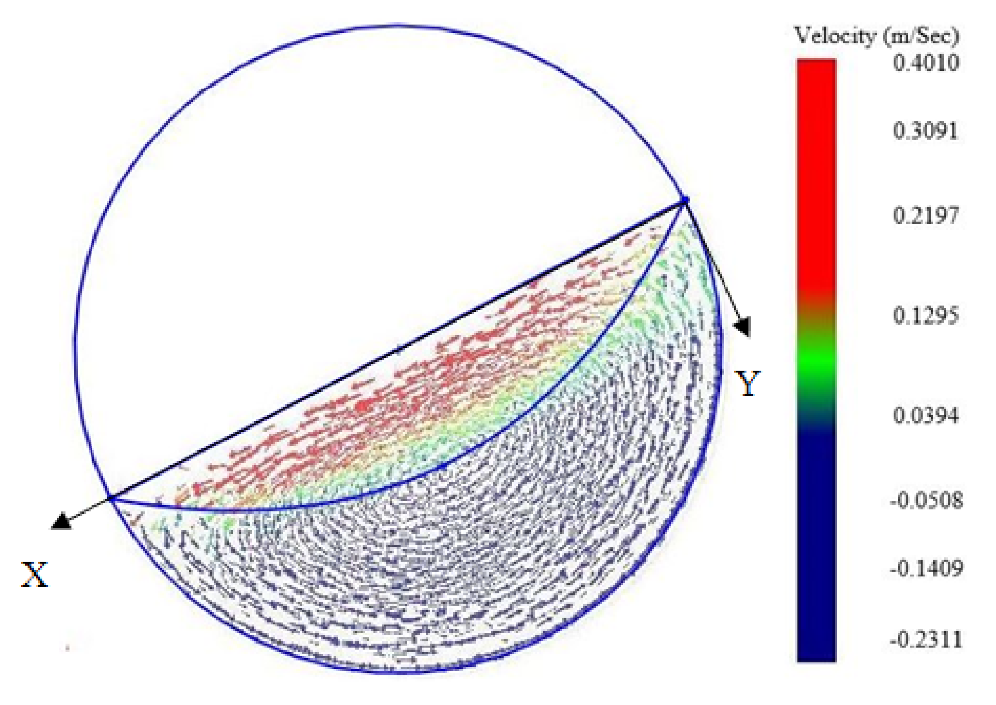
The particles in a cross section of a rotating drum normally exhibit two flow regions: active and passive. To demonstrate the existence of the active and passive regions for the inclined rotating drum,
Figure 7 gives the velocity field at a cross section for the drum with α = 10°, where a X-Y coordinates is defined. The velocity is positive if the projection of the vector for the velocity is in the positive direction of the x axis. The length of a velocity is proportional to its magnitude. It can be seen that the velocity of the particles increases with the radial height of the drum from the bottom to the top surface of the bed along the Y axis. This velocity profile is similar to that observed in the experiments and simulation studies for horizontal rotating drums [
24,
30]. The active and passive regions have been shown clearly in the figure. The two regions have also been observed in other locations for all angles of inclination considered in this work. It should be noted that the rotation speed of 30 rpm and drum diameter of 170 mm constitute to the Froude number of 0.08551. Based on the result obtained in [
23] for a horizontal rotating drum, the flow should be in the cascading motion. However, the cascading behavior shown in [
23] is not clear in the present study. The possible reason is that the system in this work has different simulation conditions. Further studies will be conducted to understand the flow regimes for inclined rotating drums.
To calculate the area ratio of a rotating drum, the determination of particle velocity profile on the bed surface is important. To analyze the surface velocity profile, locations were first defined at each 50 mm distance along the length of the drum, and then the cuboids of 5 mm × 5 mm × 5 mm were created across the bed surface at each defined location. At each cuboid location, the velocity in the X direction was calculated at
t = 30 s.
Figure 8 shows the variation of the velocity of particles on the bed surface along the
X direction at
La = 425 mm for the case with α = 10°. The velocity has the highest value at the central region of the bed surface and very small values at the edges. A similar profile has also been observed in the previous experiment for horizontal rotating drums [
24]. It is noted that there is a big jump from the first point to the second. The first point corresponds to the higher end of the surface layer of the bed, where the particles stop and then change the direction of their movements. Therefore, there is a big change in the value of the velocity between the first and second points. The particle velocity
ux on the bed surface obtained by the simulation can be fitted by a polynomial function. Based on the velocity profile,
B,
δ(
x) and finally the area ratio can be determined by using Equations (13)–(17). Similar ways can be used to calculate the values of the area ratio at other locations for all angles of inclination.
Figure 9a shows that variation of the area ratio along the length of the drum for different angles of inclination of the rotating drum. In the case of the horizontal drum, the area ratio remains almost constant across the length of the drum. With an increase in the angle of inclination, the area ratio increases towards the upper side of the drum concerning the center of the drum. This is due to the reduction of the volumetric fill in that region. Lower volumetric fill implies fewer particles which lead to the increased transmission of excitation force to the particles in the rotating drum. This leads to an increase in the motion of the particles in the region in which the area ratio increases. In the case with α = 5°, the area ratio initially is lower as compared to the horizontal and then increases along the length of the drum. The increase in the area ratio is due to the reduction of the volumetric fill. The similar pattern is followed by the cases with α = 10° and 15° in the latter half of the length of the drum. However, at lower part of the drum of the two cases, the area ratio is very small nearly at the bottom of the drum, and then spikes up with the drastic reduction of volumetric fill. This phenomenon occurs due to the increased retraction torque propagation through the particles from the bottom towards an upward direction. This increased retraction torque is caused by the increased contact force among the particles for higher angle of inclination. Instant peaks are also observed in α = 10° and 15° at the lower position. This is because at the bottom the volumetric fill is nearly equal to 1 which results in the area ratio to be almost zero as there is no percolation happening between the particles due to the lack of space. Thereafter, the volumetric fill starts decreasing which gives rise to the particle movement and granular percolation. The change in volumetric fill causes the increase of the area ratio.
To further demonstrate the impact of the angle of inclination on the area ratio, the average area ratio is calculated and plotted against the angle of inclination of the drum, as shown in
Figure 9b. It can be observed that with the increase in the angle of inclination, the average area ratio increases until a peak at α = 10°, thereafter reduces drastically. This indicates that the average area ratio of 10° inclination is the highest compared to other inclinations considered in this study.
3.4. Mixing Efficiency
Figure 10a shows the variation of the Lacey mixing index for the whole bed with time for different angles of inclination. With the start of the rotation of the drum, particles tend to mix and reach a certain level of mixing index. Then the mixing index increases approximately linearly until reaching a steady state. It can be observed that in the initial few seconds of the simulations, the mixing index drastically increases for all cases. This is due to the percolation of small particles in the gaps of the large particles. Once the particle flow bed is fully matured, the percolation reduces and the mixing mostly happens in the active regime of the flow. Hence the rate of mixing reduces after the initial rise and the mixing index increases relatively slowly with time until the steady state is achieved. In the movements of particles, the axial and radial mixings happen simultaneously, leading to greater mixing index for α = 5° and 10° as compared to the horizontal one. Compared to α = 10°, the case of α = 5° has a less axial mixing, hence a lower Lacey mixing index. In the case of α = 15°, the high mass flow rate of the particles towards the bottom of the drum results in large volumetric fill at the part near the bottom of the drum. In the part, particle percolation is restricted after few seconds of the simulation due to a lack of space. Therefore, the mixing of the particles, especially in the axial direction, is less as compared to other cases. As a result, this case has the lowest mixing index among the angles of inclination considered. To further consider the effect of angle of inclination, the time-averaged Lacey mixing index is calculated during the steady state (after
t = 30 s). The Lacey mixing index of the whole bed is plotted with a variable angle of inclination of the drum as shown in
Figure 10b. It shows that with an increase in the angle of inclination, the Lacey mixing index increases and reaches a peak at α = 10°, and then decreases drastically. Compared to α = 0°, 5° and 15°, the case with α = 10° has 7.2%, 3.7%, and 32.6% higher Lacey mixing index, respectively. This indicates that the particle mixing efficiency can be increased with the optimization of the angle of inclination of drums.
As the inclined rotating drum is a three-dimensional system, it is of importance to understand the Lacey mixing index along the length of the drum. To perform such an analysis, different cuboids of 170 × 170 × 17 mm were defined at cross sections with a 50 mm distance between two neighboring sections along the length of the drum. Each cuboid was further divided into small cubes with the same size as that used to measure the whole bed mixing index. A similar procedure was applied to calculate the Lacey mixing index for each cuboid.
Figure 11 shows the variation of the Lacey mixing index along the length of the drum for different angle of inclination. In the case of the horizontal rotating drum, the Lacey mixing index remains almost constant along the length of the drum, similar to that verified in a two dimensional analysis [
21]. The index is a bit higher at the ends of the drum, same as the area ratio. This is due to the effect of the side walls of the drum. For the cases with inclination, the Lacey mixing index varies with the length of the drum. In the case of α = 5°, the index is lower than that for the horizontal drum at the lower end, and then increases along the length of the drum. For the cases of α = 10° and 15°, the Lacey mixing index has relatively low value near the lower end of the drum. It increases drastically to reach a peak, and then decreases to a value. After that, the index exhibits an increase trend with the length of the drum.
Based on the results shown in
Figure 9a and
Figure 11, the mixing index and area ratio have a similar variation trend with the length of the drum. They are related to the volumetric fill of particles. To further demonstrate the relations among the three properties,
Figure 12 shows the dependence of the area ratio and Lacey mixing index on the volumetric fill from all cases considered in the present study. At a rotating speed of 30 rpm considered in the present work, the volumetric fill of below 20% lies in the slumping flow regime, and above 80% lies in a centrifuging regime. In these two regimes, mixing phenomena rarely occur [
23]. Therefore, the data in the two regimes has been excluded when plotting the figure. It can be seen in
Figure 12 that both the Lacey mixing index and area ratio can be fitted by quadratic functions, and they decrease with the increase of the volumetric fill. The Lacey mixing index is directly proportional to the area ratio, which is similar to the finding of Xiao et al. [
30] for a horizontal rotating drum.


