Abstract
A compact heat integrated reactor system (CHIRS) of a steam reformer, a water gas shift reactor, and a combustor were designed for stationary hydrogen production from ethanol. Different reactor integration concepts were firstly studied using Aspen Plus. The sequential steam reformer and shift reactor (SRSR) was considered as a conventional system. The efficiency of the SRSR could be improved by more than 12% by splitting water addition to the shift reactor (SRSR-WS). Two compact heat integrated reactor systems (CHIRS) were proposed and simulated by using COMSOL Multiphysics software. Although the overall efficiency of the CHIRS was quite a bit lower than the SRSR-WS, the compact systems were properly designed for portable use. CHIRS (I) design, combining the reactors in a radial direction, was large in reactor volume and provided poor temperature control. As a result, the ethanol steam reforming and water gas shift reactions were suppressed, leading to lower hydrogen selectivity. On the other hand, CHIRS (II) design, combining the process in a vertical direction, provided better temperature control. The reactions performed efficiently, resulting in higher hydrogen selectivity. Therefore, the high performance CHIRS (II) design is recommended as a suitable stationary system for hydrogen production from ethanol.
1. Introduction
Hydrogen has been used widely in many industrial processes such as petroleum, petrochemical, steel and food. Nowadays, hydrogen, which is also considered as a clean fuel, has recently been used in vehicular systems to reduce fossil fuel usage [1,2]. Therefore, hydrogen utilization demand has dramatically increased, leading to insufficient hydrogen supply with restricted hydrogen sources. In conventional processes, hydrogen is produced from steam reforming of natural gas (NG) or liquefied petroleum gas (LPG). The process emits gaseous carbon dioxide and causes environmental problems. Alternative green fuels such as biogas, ethanol and bio-oil have been suggested for hydrogen production [3,4,5,6,7,8,9]. Ethanol, a harmless liquid at room temperature, has potential to be a good candidate for steam reforming [10,11,12,13,14,15,16,17], since it can be produced from agricultural products and bio-waste fermentation.
Ethanol steam reforming is a highly endothermic reaction, and it produces various by-products, such as methane and acetaldehyde [18,19]. The reaction normally occurs at high temperatures, beyond 973 K, to reduce the by-products. An external heat source is required to maintain a high temperature for the reforming reaction. However, a reverse water gas shift strongly occurs at high temperature. The reaction produces carbon monoxide and decreases hydrogen production. Thus, a water gas shift reactor, which operates at lower temperatures, is necessary to shift the reaction equilibrium and to increase the hydrogen production rate [20,21,22,23,24]. A compact reactor system consisting of combustor, reformer and shift reactor is proposed in this study for hydrogen production from ethanol.
For hydrogen production, multifunctional reactors, which combine a combustor within a reformer, have been studied extensively. For these reactors, heat is normally generated from combustion and transfers to the reformer side through the reactor’s wall [25,26,27,28]. A microreactor, for instance, consisting of two parallel channels for methanol combustion and methanol steam reforming was studied by Andisheh Tadbir and Akbari [25]. An assembly of 1540 small reactor sets occupying a total volume of about 91 cm3 can produce enough hydrogen for operating a typical 30-W PEM fuel cell. A reformer that integrated the steam reforming reaction and catalytic combustion in a reactor was also investigated by Grote et al. [26]. Experiments and simulations were employed and the model was successfully validated with experimental data of 4 kW, 6 kW and 10 kW reformers. As reported in another study, a metallic monolith catalyst for methane catalytic combustion and methane dry reforming was examined by Yin et al. [27]. Methane conversion in dry reforming reached 93.6% with 81.9% of heat efficiency. For water gas shift reactor integration, a compact steam reformer was investigated numerically by Seo et al. [29]. Methane was converted to syngas in a steam reforming section and then flowed to a water gas shift section. In the product stream, methane conversion and CO concentration were 87% and 0.45%, respectively. Furthermore, Hayer et al. employed the integrated micro packed bed reactor heat exchanger (IMPBRHE) for the synthesis of dimethyl ether [30]. This work presented a comparison between the temperature profiles along the length of IMPBRHE and that of the fixed bed reactor under the same operating conditions, investigated via COMSOL Multiphysics. Their results showed that the temperature gradients in the microchannel reactor were steeper than those in the lab-scale fixed bed reactor. It could be concluded that the microchannel reactor offered high heat transfer due to its high surface area-to-volume ratio. All of these factors indicate that the multifunctional reactor combined with the compact system has a high possibility for hydrogen production from ethanol, giving two benefits as follows: (1) heat integration to optimize energy consumption and (2) good mass and heat transfer owing to high surface area to volume ratio.
This study aimed to design a compact reactor system consisting of a combustor, a steam reformer and a shift reactor for stationary hydrogen production from ethanol. Regarding the step of process concept development, different processes integration concepts including typical sequential steam reformer and shift reactor (SRSR), SRSR with energy management by water splitting (SRSR-WS) and a compact heat integrated reactor system (CHIRS) were preliminarily examined via Aspen Plus software. The highest level of process concept development, CHIRS, was further studied in detail via COMSOL Multiphysics software. The Aspen Plus software was used to determine the suitable concept from the three integration concepts mentioned above, whereas the COMSOL Multiphysics software was applied to investigate the transport phenomena inside the reactors and finally to determine the proper configuration of the suitable case considered by Aspen Plus software.
2. Modeling and Simulation
2.1. Description of Reformer Concept Development
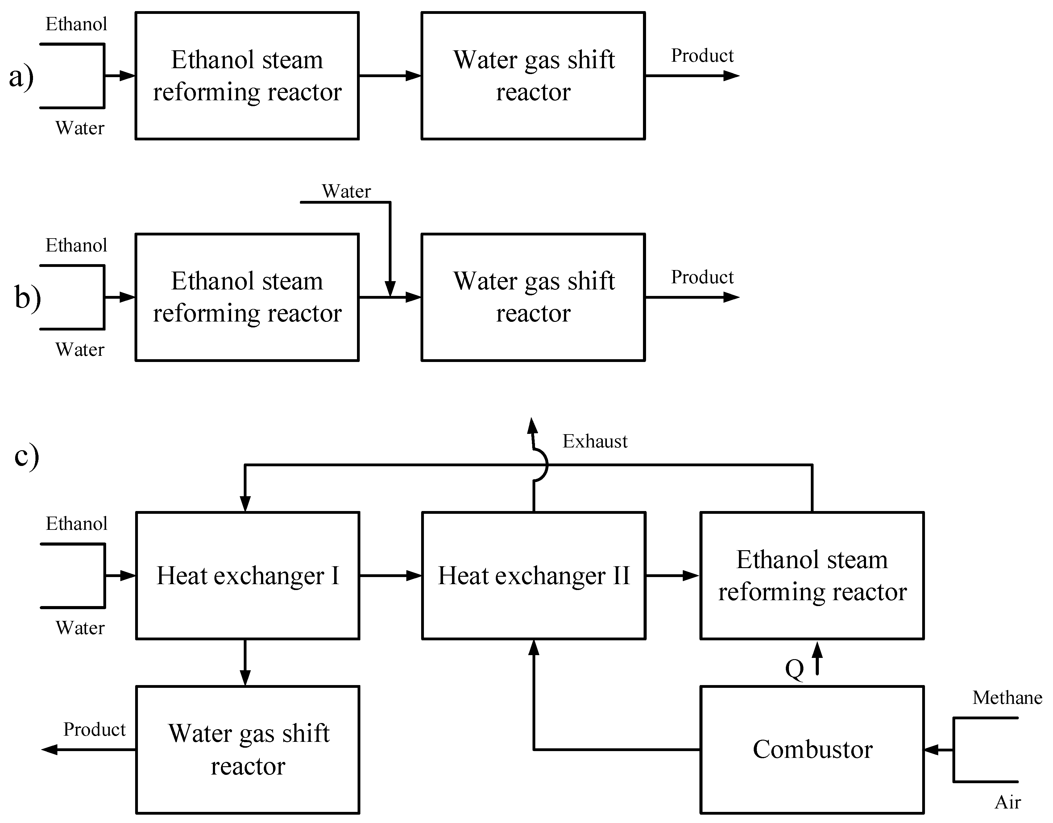
As illustrated in Figure 1, there are three steps of ethanol steam reformer concept development considered in this work, i.e., typical sequential steam reformer and shift reactor (SRSR), SRSR with energy management by water splitting (SRSR-WS) and compact heat integrated reactor system (CHIRS). For the conventional one, SRSR, ethanol and water are fed to the reformer at the desired temperature and pressure and the product stream flows to the shift reactor at the same operating condition as shown in Figure 1a. However, to operate the shift reactor efficiently, it should be carried out at low temperature to achieve a higher hydrogen production. Therefore, for the second level of process concept development, SRSR-WS, additional water is used to mix with the product stream of the reformer to quench to the desired temperature of the shift reactor. This stream is then fed to the adiabatic shift reactor (Figure 1b). However, for the first two concepts, the heat management in each process has not been considered. For example, an ethanol steam reformer typically requires heat from the external heat source and heat from the product stream at high temperature to be recovered. Hence, the heat management is intentionally included in the final step of process concept development, CHIRS. As displayed in Figure 1c, the heat requirement for the process is supplied from a combustor, which uses methane as a fuel. Two heat exchangers are installed to preheat the reactant. Moreover, the reformed gas from the ethanol steam reformer at high temperature can be reduced to the suitable temperature for the shift reactor by diverting heat to the reactant via heat exchanger I. To reduce heat loss at the outlet and improve the process efficiency, the temperature of the combusted gas after exchanging heat with the reactant (Heat exchanger II) is properly limited at 523 K.
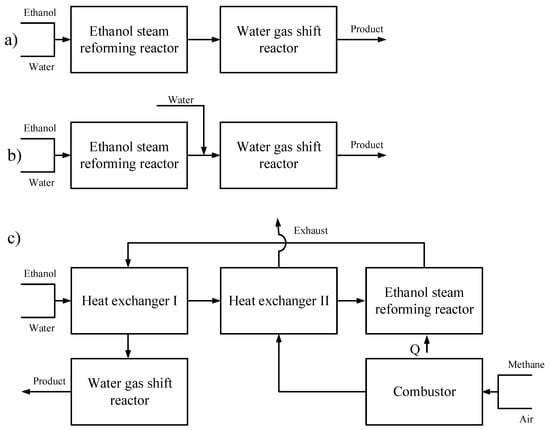
Figure 1.
Different ethanol steam reformer concepts: (a) Typical sequential reformer and shift reactor (SRSR), (b) SRSR with energy management by water splitting (SRSR-WS), and (c) Compact heat integrated reactor systems (CHIRS).
To evaluate these concepts, a simulation via Aspen Plus software was selected. Aspen Plus software is widely used for process simulations in chemical industries. The program contains standard and ideal unit operations such as reactor and heat exchanger models. For steam reforming processes, reactors including an ethanol steam reformer, a shift reactor, a combustor and a heat exchanger are generally conducted in the simulation. To simplify the simulations, a thermodynamic equilibrium reactor, RGibbs reactor, was assumed. In the RGibbs reactor model, Gibbs free energy minimization is performed to determine the product compositions. For an ethanol steam reforming reaction, possible products including hydrogen (H2), carbon monoxide (CO), carbon dioxide (CO2), methane (CH4), acetaldehyde (CH3CHO), acetone (C3H6O), dimethyl ether (C2H6O), ethane (C2H6), ethylene (C2H4) and coke (C) were specified [18,19,31].
In the simulations, ethanol reactant was fed at 1 kmol/h at standard temperature and pressure. The operating condition for the ethanol steam reforming reaction was estimated to find an appropriate range of temperature, pressure and steam to ethanol ratio as discussed later in Section 3.1.1. A proper condition was employed in the reformer concept investigation. Efficiency as defined in Equation (1) is used as an indicator in this study.
2.2. CHIRS Designs in Detail
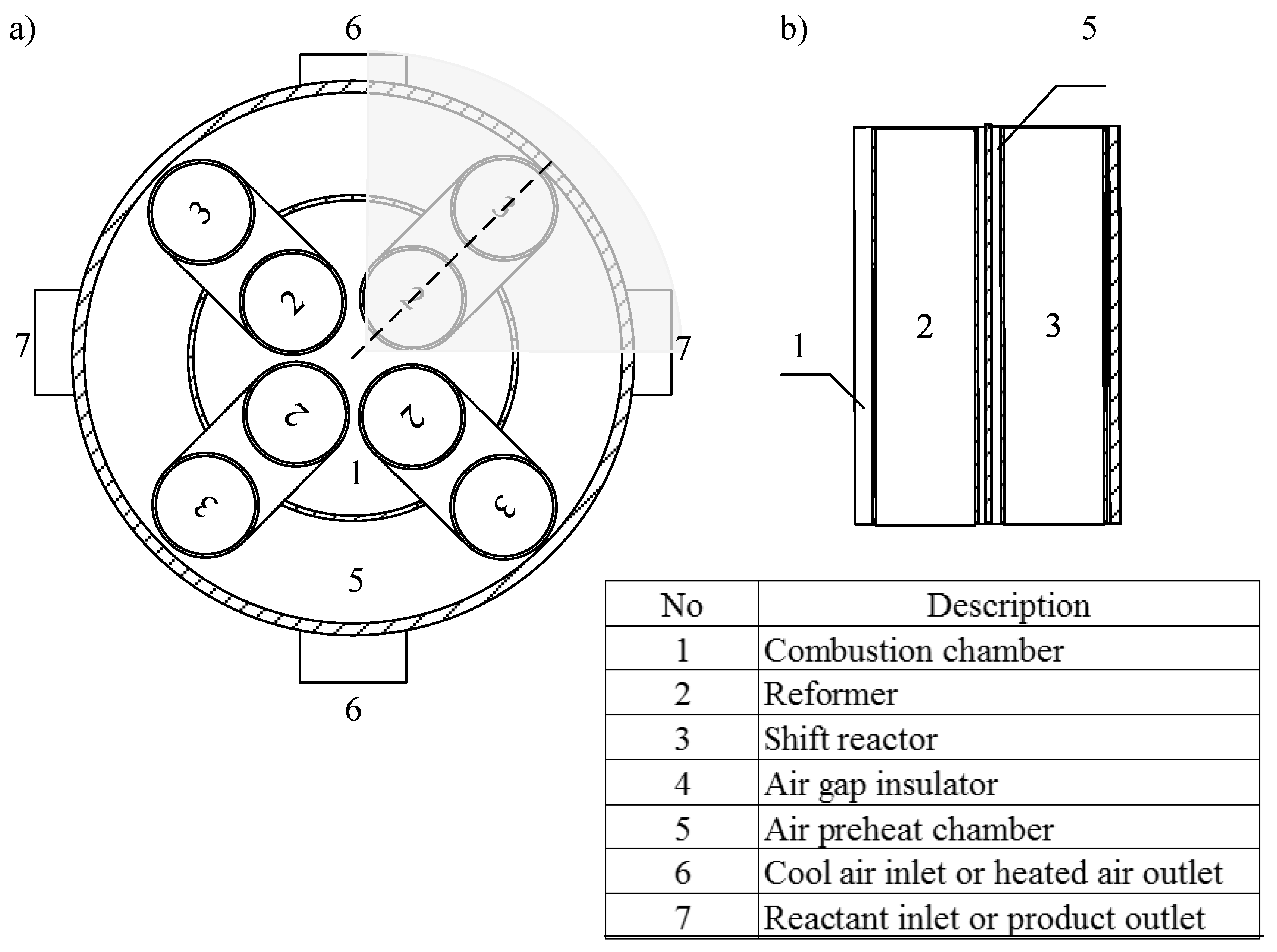
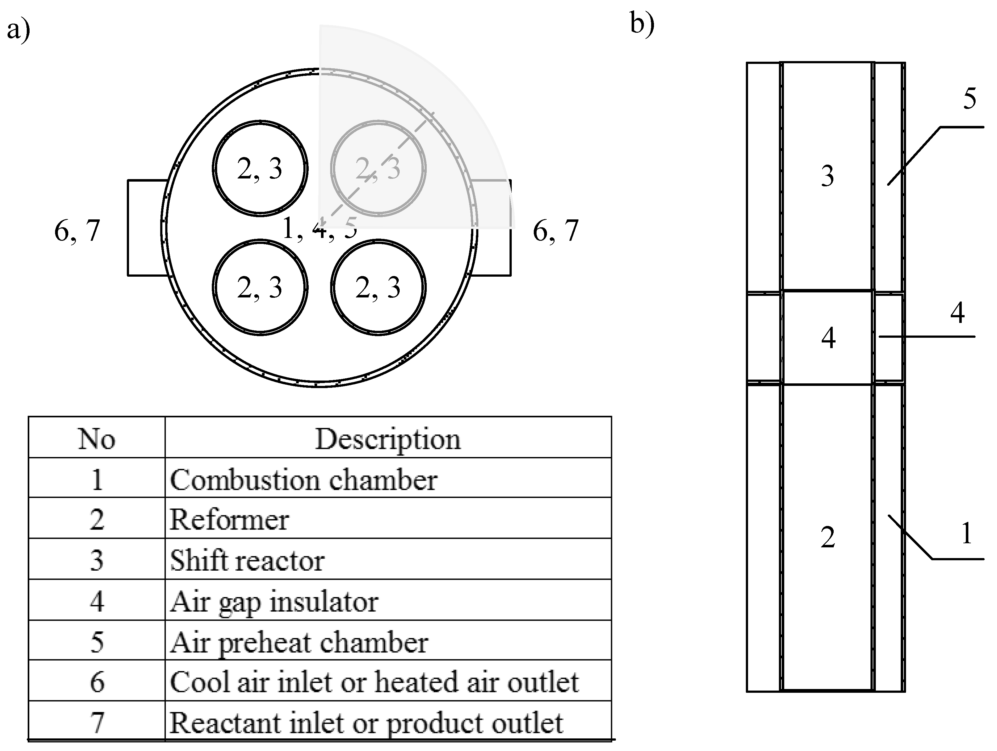
This compact reactor system, combining combustor, reformer, shift reactor and two heat exchangers within a structure, was designed to be the same as the combined reformer with heat exchanger network concept. The process was developed and named as a compact heat integrated reactor system (CHIRS). For the first CHIRS design (CHIRS (I)) as illustrated in Figure 2, the ethanol steam reformer was placed inside the combustion chamber. The reformer received heat directly from the combustion through the reactor’s wall, which performed as a heat exchanger. The reformed gas from the reformer was fed to the shift reactor located in the air preheat chamber. The reformed gas was quenched by air and the water gas shift reaction was shifted forward, leading to an increase in hydrogen production. For the CHIRS (I) design, the sections were integrated in the radial direction. The combustion chamber was enveloped by an air preheat chamber as shown in Figure 2a. However, there was another interesting design designated as CHIRS (II), which combined the processes in the vertical direction as shown in Figure 3. For the second design, an air gap insulator was set between the reformer and the shift reactor.
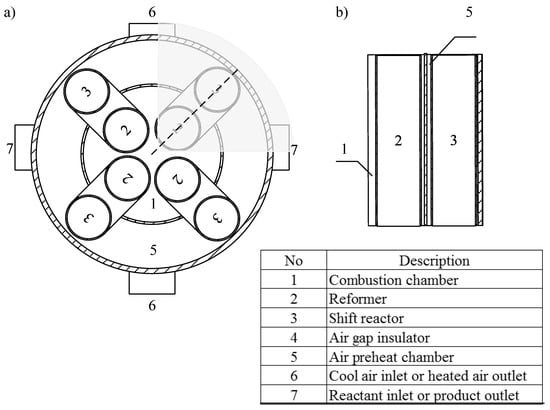
Figure 2.
Configuration of CHIRS (I) shown in (a) top view and (b) cross sectional view (dotted line).
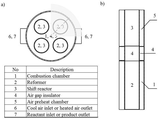
Figure 3.
Configuration of CHIRS (II), shown in (a) top view and (b) cross sectional view (dotted line).
Owing to the study of CHIRS in detail, three-dimensional computational fluid dynamic (CFD) simulation was employed to examine the process performance of CHIRS design using COMSOL Multiphysics software. The gray area presented in Figure 2a and Figure 3a was set as the calculation domain for CHIRS (I) and CHIRS (II), respectively. Tetrahedral mesh was created to cover the structure. The mesh size was specified as extremely fine inside the ethanol steam reforming and water gas shift reactors due to the presence of reaction in these domains obtaining a high gradient in concentration and temperature profiles. Total mesh number of CHIRS (I), 4.02 × 10⁵ elements, was higher than that of CHIRS (II), 2.40 × 10⁵ elements, because the former was larger in size than the latter.
Inside the module of COMSOL Multiphysics, several governing equations are taken into account. The steady state governing equations, i.e., mass, momentum, energy and chemical species conservation equations, which can be written in Equations (2)–(5), respectively, were simultaneously considered.
The gravity term in Equation (3) was neglected. The related reactions, which were ethanol steam reforming and water gas shift, were computed using kinetic models. For the ethanol steam reforming reaction, the reactions are divided into Equations (R1)–(R4).
C2H5OH → CH3CHO + H2
C2H5OH → CH4 + CO + H2
CO + H2O ↔ CO2 + H2
CH3CHO + 3H2O ↔ 2CO2 + 5H2
Kinetic models of these reactions over a Co3O4–ZnO catalyst were adopted from Uriz et al. as listed in Equations (6)–(9) [32].
where is partial pressure of component i in bar and is defined as shown in Equation (10).
In the shift reactor, the Cu/ZnO/Al2O3 catalyst has been typically used for the water gas shift reaction (Equation (R3)). The kinetic model was proposed by Amadeo and Laborde as listed in Equation (11) [22].
Fluid properties were simplified and assumed as steam and air for the reforming stream and combusted gas, respectively. The reactor structure was stainless steel. The porous media was considered as alumina according to the general catalyst support material.
3. Results and Discussion
3.1. Preliminary Study of Reformer via Aspen Plus
3.1.1. Effect of Operating Conditions on Reaction Performance
Operating parameters including temperature, pressure and steam to ethanol ratio were determined to find a suitable operation range that provided high hydrogen production without coke formation in the process. To study the effects of temperature and pressure, water was firstly fed at 3 kmol/h in the conventional SRSR reactor according to the stoichiometry of the ethanol steam reforming reaction.
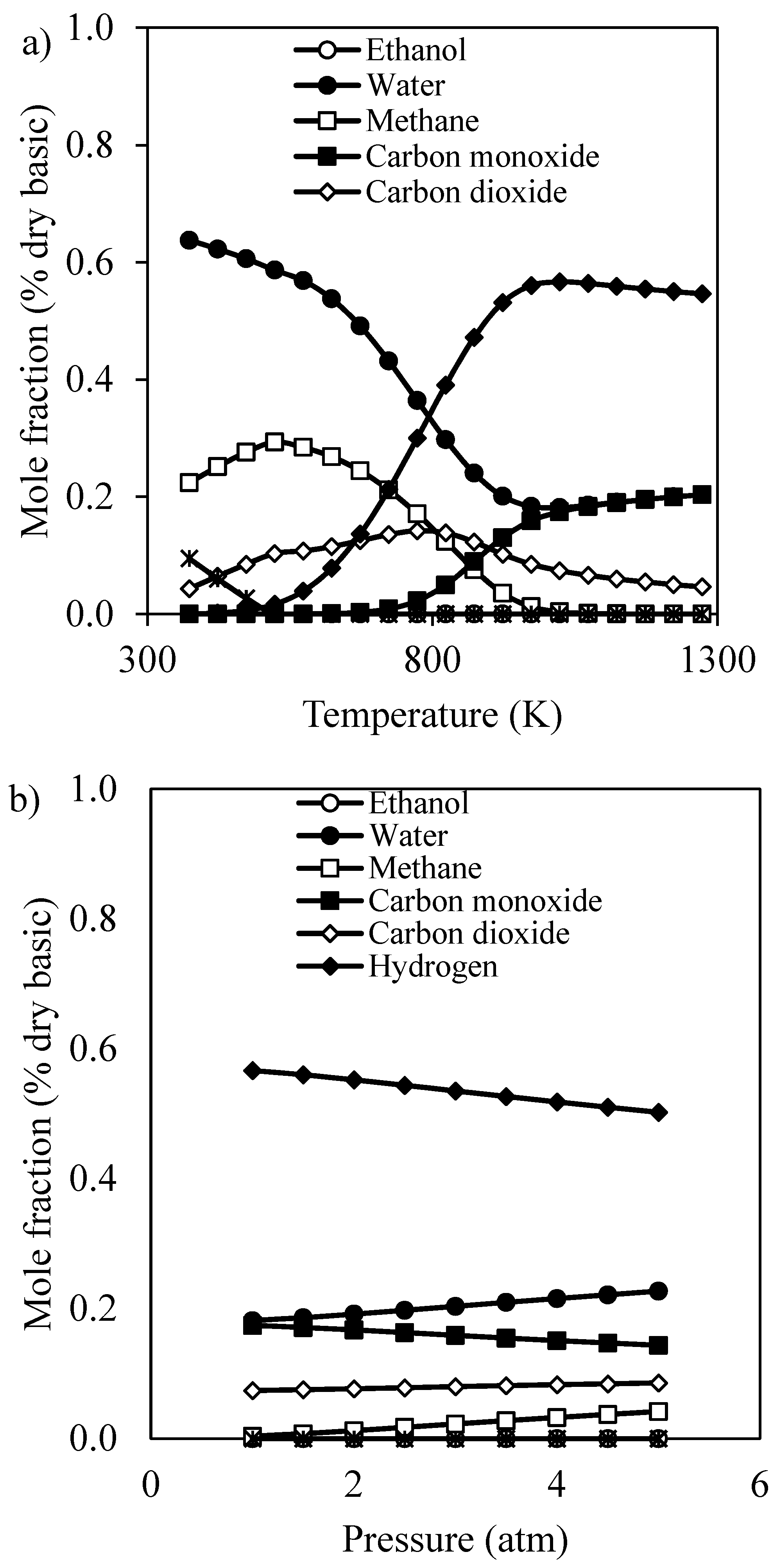
When considering the atmospheric pressure (1 atm), the effect of operating temperature in the range of 400–1300 K on product distribution was reported as shown in Figure 4a. Methane and syngas were mainly produced in this reforming temperature range. Ethanol was completely converted to intermediate gas while by-products including acetaldehyde, acetone, dimethyl ether, ethane and ethylene were absent in the product stream due to the non-thermodynamic stability of these components [19,31]. Methane steam reforming and water gas shift were main reactions in this reformer. Hydrogen production increased with an increase in reforming temperature and reached the optimum conversion at 1023 K. Below 1023 K, hydrogen production was increased as a result of methane steam reforming, which was a major reaction, whereas the reduction in hydrogen production at a higher temperature than 1023 K occurred because hydrogen was reasonably consumed by the reverse water gas shift reaction. Eventually, the ethanol steam reforming for hydrogen production was appropriately carried out at a moderate temperature of 1023 K.
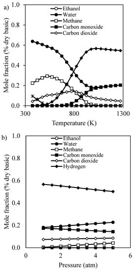
Figure 4.
Mole fraction of product stream at a steam to ethanol ratio of 3 for (a) effect of temperature (P = 1 atm), and (b) effect of pressure (T = 1023 K).
As shown in Figure 4b, the effect of pressure in the range of 1–5 atm at the proper temperature, 1023 K, was further investigated. As the operating pressure increased, the methane steam reforming was suppressed, resulting in the reduction in hydrogen production with increasing methane composition in the reformed gas. The reaction equilibrium shifted backward as the pressure increased according to mole expansion of the steam reforming reaction. Therefore, the hydrogen production from ethanol was preferentially operated at low operating pressure, especially 1 atm, due to simple design and operation.
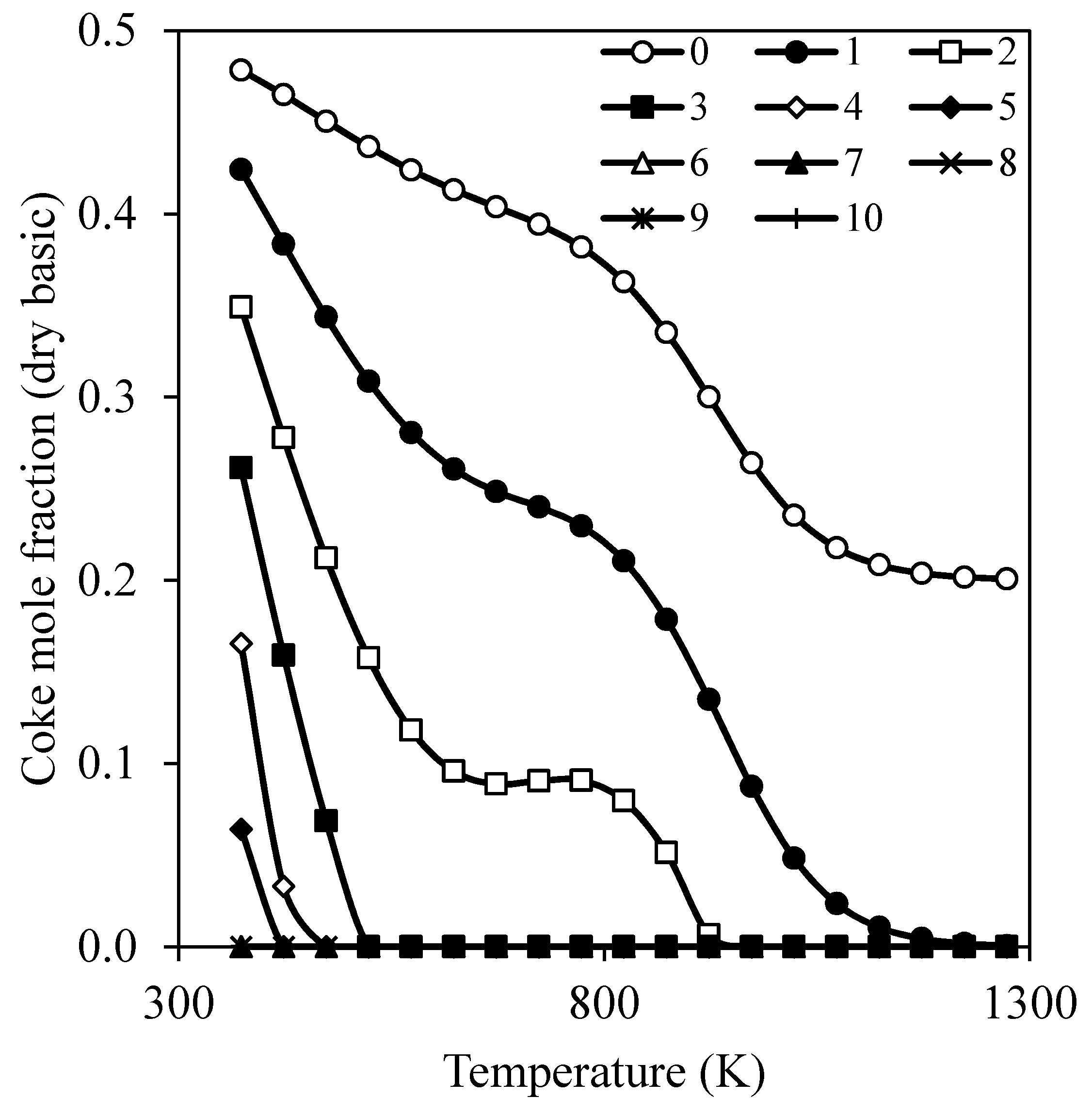
Coke formation, which causes catalyst deactivation and limits the operation time, is an important indicator for operating condition selection. According to Montero et al. [33], acetaldehyde, ethylene, and non-reacted ethanol are main precursors for coke formation on the metal sites at low space-time. At high space-time, due to a change in the coke mechanism, the CH4 and CO become the main precursors leading to a filamentous and partially graphitic coke. The increases of temperature and ethanol to steam ratio along with a significantly prolonged reaction lead to coke formation. The catalyst deactivation is attenuated by reducing the concentration of coke precursors and increasing coke gasification, especially at high temperature. Therefore, this study considered the coke formation at the reforming pressure of 1 atm with various reforming temperatures and steam to ethanol ratios as presented in Figure 5. Coke formation decreased with increasing operating temperature and steam to ethanol ratio. When the steam to ethanol ratio was below 3, coke strongly appeared over the reforming temperature range of 400–1300 K. Beyond the reforming temperature of 523 K and a steam to ethanol ratio of 3, coke formation then became negligible. Thus, an operating condition at 523 K and steam to ethanol ratio of 3 was the lowest boundary for the ethanol steam reforming process without any coke formation.
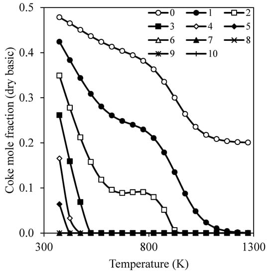
Figure 5.
Coke formation at various steam to ethanol ratios and operating temperatures.
An appropriate operating condition for ethanol steam reforming was at the reforming temperature of 573–1073 K, steam to ethanol ratio of 3–5 and reforming pressure of 1 atm. This condition provided high hydrogen production without coke formation and was further employed in the reformer concept study.
3.1.2. Sequential Steam Reformer and Shift Reactor (SRSR)
In this conventional reactor system (Figure 1a), the ethanol steam reformer and water gas shift reactor were carried out under the same operating condition. This can be considered as a single reactor for simulation in the Aspen Plus program.
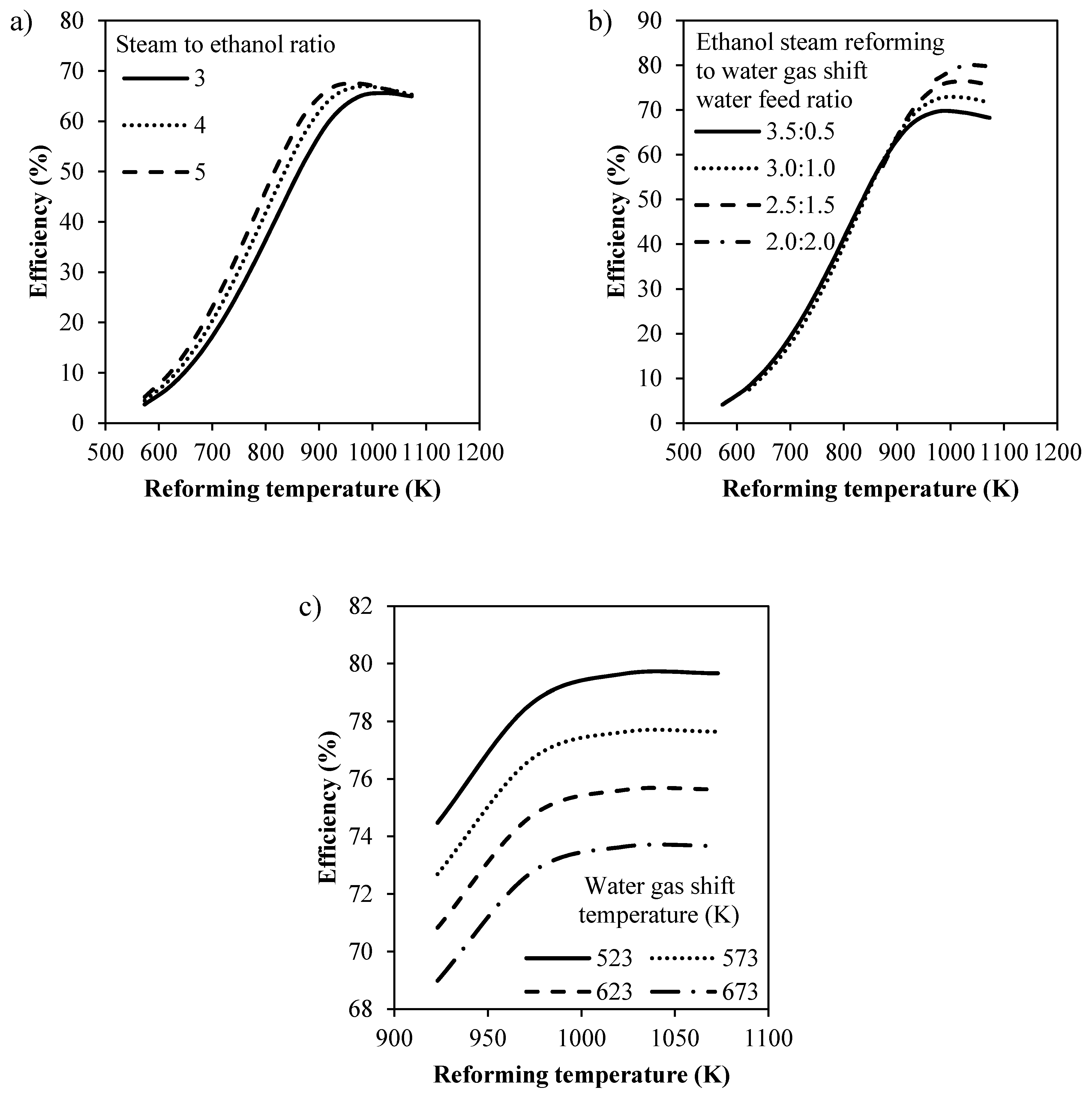
In Figure 6a, the influence of reforming temperature and steam to ethanol ratio on the process efficiency is displayed. The reaction equilibrium shifted forward, resulting in higher hydrogen production and efficiency when increasing the steam to ethanol ratio. The process efficiency also improved with increasing reforming temperature up to 973 K. Beyond this temperature, its value reduced because the reverse water gas shift was the dominant reaction. Consequently, the best operating condition for SRSR was 973 K and a steam to ethanol ratio of 5, obtaining the highest efficiency at 67.50%. However, a large amount of carbon monoxide, ca. 14%, still remained in the product stream because the water gas shift reaction performed poorly at a high temperature. Thus, a water gas shift reaction that operated separately at lower temperature was suggested to reduce some carbon monoxide and improve the process efficiency. The reduction in reformed gas temperature from the ethanol steam reformer was proposed by quenching with water before flowing to the shift reactor. This will be discussed in the next section.
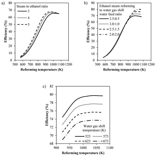
Figure 6.
Process efficiency in percent of (a) the SRSR operated at various steam to ethanol ratios and reforming temperatures under a pressure of 1 atm, (b) SRSR-WS operated at various reforming temperatures and spiting ratios of stream under a pressure of 1 atm and a steam to ethanol ratio of 4, and (c) CHIRS operated at various reforming and water gas shift temperatures under a pressure of 1 atm and a steam to ethanol ratio of 4.
3.1.3. SRSR with Energy Management by Water Splitting (SRSR-WS)
To enhance the process efficiency, water was fed directly to the water gas shift reactor as shown in Figure 1b. According to the study of previous sections, the difference in processing efficiency at a steam to ethanol ratio between 4 and 5 was insignificant. Thus, the steam to ethanol ratio of 4 was selected due to less energy requirement. In the case of SRSR-WS, the overall steam to ethanol ratio of 4 was set as a constant value for the process and water was split for ethanol steam reforming and water gas shift at different ratios. For this study, the water feeding ratio at the ethanol steam reformer to water gas shift reactor varied between 3.5:0.5, 3.0:1.0, 2.5:1.5 and 2.0:2.0.
The efficiency of this system is shown as a function of temperature in Figure 6b. The system was considered without any presence of coke formation and condensation. Therefore, the water feeding ratio at the reformer lower than 2.0 was excluded due to the limitation of coking and condensation. Significant results obviously appeared when the reforming temperature was higher than 923 K. An improvement of process efficiency occurred when water was added to the water gas shift reactor at a higher ratio. The optimum condition was performed at the reforming temperature of 1023 K and the steam to ethanol ratio at the reformer to shift reactor of 2.0:2.0, achieving the highest efficiency of 79.90%. When compared to the SRSR process efficiency, its value for SRSR-WS improved significantly by about 12.40%. For the consideration of practical design of SRSR-WS, a direct feeding of water to the shift reactor may deactivate the catalyst and cause mechanical problems. Moreover, it was difficult to design and operate the system while injecting liquid into the reformed gas stream at the high temperature zone. Therefore, the SRSR-WS was not recommended. However, another concept was then created to solve this problem by considering a better energy management.
3.1.4. Compact Heat Integrated Reactor System (CHIRS)
A heat exchanger network was utilized to enhance the process efficiency within the ethanol steam reforming process. As exhibited in Figure 1c, two heat exchangers were integrated in the process to reduce the temperature of reformed gas and exhaust gas to be compatible with the water gas shift reactor and emission to environment, respectively. They were also used to preheat the reactant, ethanol and water, for hydrogen production. As investigated earlier, we preferred that the ethanol steam reformer was operated at a high operating temperature (923–1073 K), atmospheric pressure (1 atm), and steam to ethanol ratio of 4. Natural gas, assumed to contain methane (75%) and carbon dioxide (25%) was employed as a fuel for the combustor. The combustor supplied energy to the reformer for maintaining the reforming temperature. The exhaust gas leaving the process was limited to an outlet temperature of 523 K to avoid condensation. The reformed gas from the reformer was quenched to a low temperature between 523 and 673 K and then fed to the water gas shift reactor.
The results of process efficiency at various temperatures of reformer and shift reactor are reported in Figure 6c. The efficiency decreased with an increase in water gas shift temperature, while increasing the reforming temperature led to the enhancement of efficiency. When the reforming temperature was beyond 1023 K, the efficiency was almost constant. Hence, the reforming temperature of 1023 K was recommended. The highest efficiency of 79.65% was achieved when the process was operated at 1023 and 523 K for the ethanol steam reformer and water gas shift reactor, respectively. It was found that the efficiency of CHIRS was similar to that of SRSR-WS. However, CHIRS was the process with good energy management and can be operated practically. Therefore, this system was a proper design as a combined reactor consisting of a combustor, reformer and water gas shift reactor for further study in the next section.
3.2. Study of the Compact Heat Integrated Reactor System (CHIRS) via COMSOL Multiphysics
3.2.1. Preliminary Study of CHIRS
For the design of both CHIRS (I) and CHIRS (II), as displayed in Figure 2 and Figure 3, the configuration dimension is summarized in Table 1. To simplify the simulation, the “stream in” to the combustor performed as a hot combusted gas with an inlet temperature of 1473 K. The ethanol flow rate was specified at 3.5 mmol/s with a steam to ethanol ratio of 4.

Table 1.
CHIRS (I) and CHIRS (II) dimensions.
The influence of air and combusted gas on the reactor performance was investigated for the preliminary design of CHIRS. To find a proper air and combusted gas flow rate, CHIRS (II) was employed as a base case. The flow rate of air and combusted gas was varied between 106 and 1060 L/min.
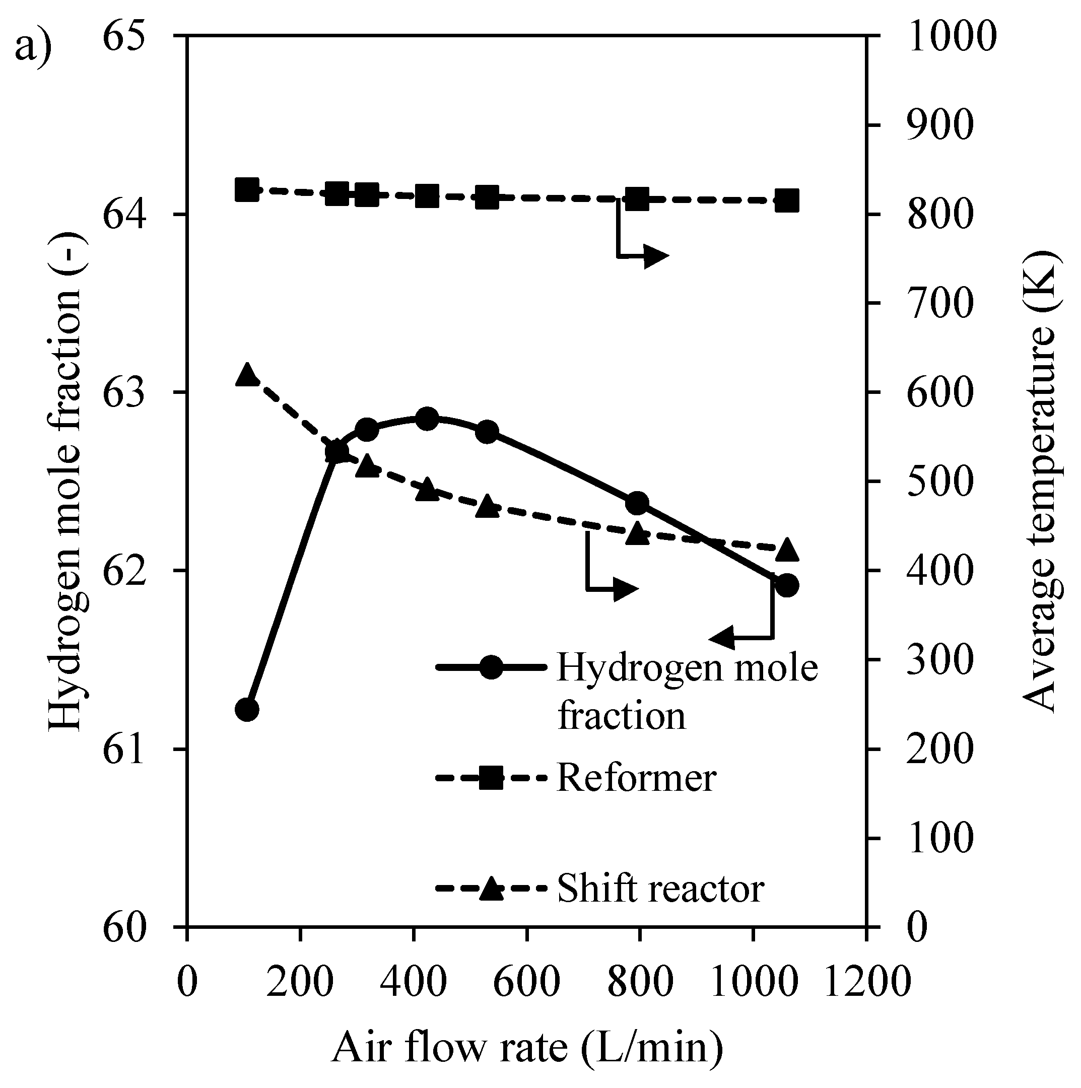
In Figure 7a, at a higher air preheat flow rate in the air preheat chamber, a significant decrease in shift reactor temperature occurred while the reforming temperature was slightly reduced. The hydrogen fraction at the outlet stream of the process had the optimum value when air flow rate was 318 L/min. Since the steam reforming was a dominant reaction in the reformer, a lower reforming temperature led to less hydrogen production, even though the low shift reactor temperature could convert carbon monoxide and then boost hydrogen production. For the study of air flow rate, hydrogen could be produced in the range of 61–63% by changing the air flow rate from 106 to 1060 L/min.
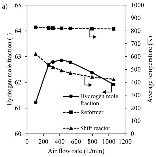
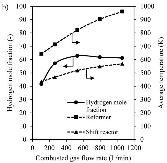
Figure 7.
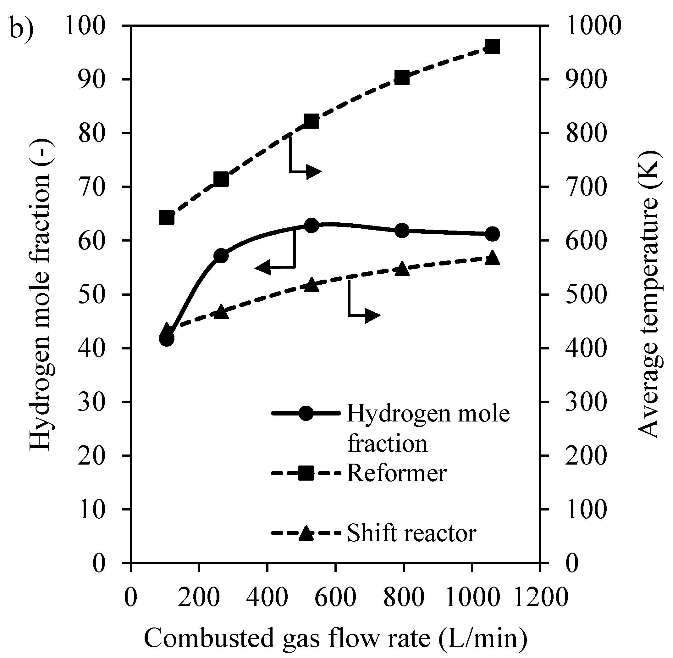
Influence of the (a) air preheat and (b) combusted gas flow rate on mole fraction of hydrogen and average temperature of the reformer and shift reactor.
The influence of combusted gas flow rate on the operating temperature of each section and hydrogen gained from the process is shown in Figure 7b. Average temperatures of both reactors were definitely enhanced with increasing the combusted gas flow rate. The steam reforming reaction rate in the reformer was absolutely improved at higher temperature, leading to an increase in hydrogen production. However, the hydrogen fraction was slightly lower when the combusted gas flow rate was beyond 530 L/min. The average shift reactor temperature was higher at the higher flow rate of combusted gas and limited the equilibrium of the water gas shift reaction after a complete conversion of ethanol and acetaldehyde. As a consequence, the combusted gas flow rate should be operated properly at 530 L/min to obtain the highest hydrogen production.
Air and combusted gas acted as a heat sink and heat source of the CHIRS. The reformer temperature decreased with increasing air flow rate, whereas it was increased by increasing the flow rate of the combusted gas. A better control of reformer and shift reactor temperatures to achieve hydrogen improvement was ascribed to the optimal air and combusted gas flow rate of 318 and 530 L/min, respectively. This condition was further used in computing the reactor performance of CHIRS (I) and CHIRS (II) as presented in Section 3.2.2 and Section 3.2.3.
3.2.2. Characteristics of CHIRS (I)
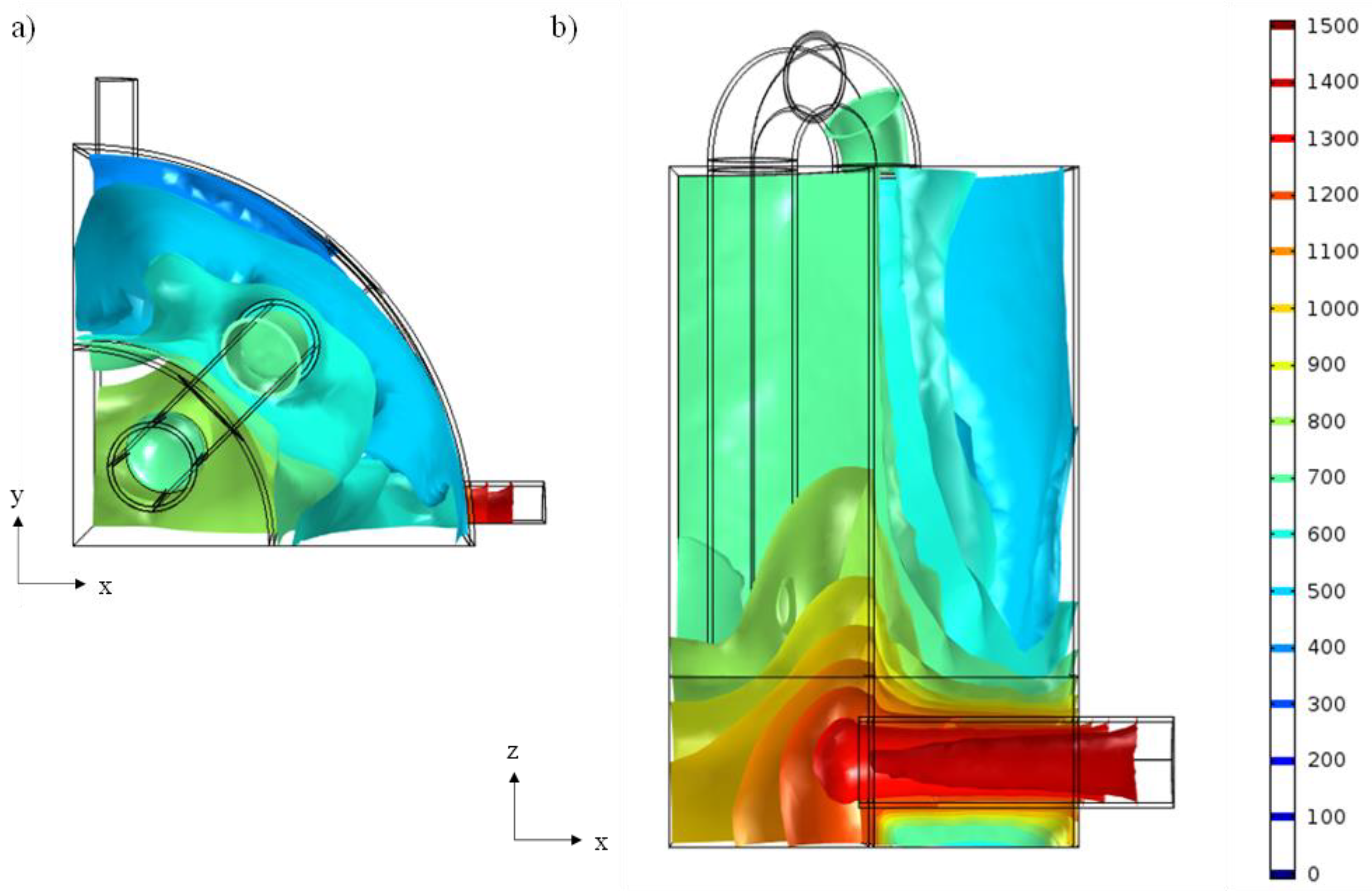
In the calculation domain inside the CHIRS (I) configuration, the temperature profile presentation as an isothermal contour is depicted in Figure 8. Combusted gas was intended to supply heat to the steam reformer, but heat was also conducted to the shift reactor through the wall between sections resulting in a higher temperature of the shift reactor. A small temperature gap between both sections occurred when the reactors were at 700–800 K for the reformer and 400–700 K for the water gas shift reactor (Figure 8b). For this CHIRS (I) design, the operating temperature control of each zone was poor, due to the presence of a low reforming temperature (752.15 K in average) and high shift reactor temperature (564.12 K in average).
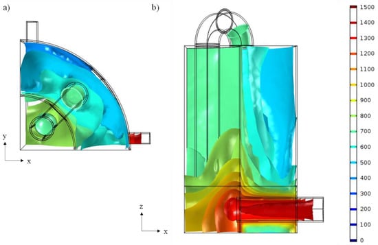
Figure 8.
Temperature profile of CHIRS (I) in the (a) XY plane and (b) XZ plane.
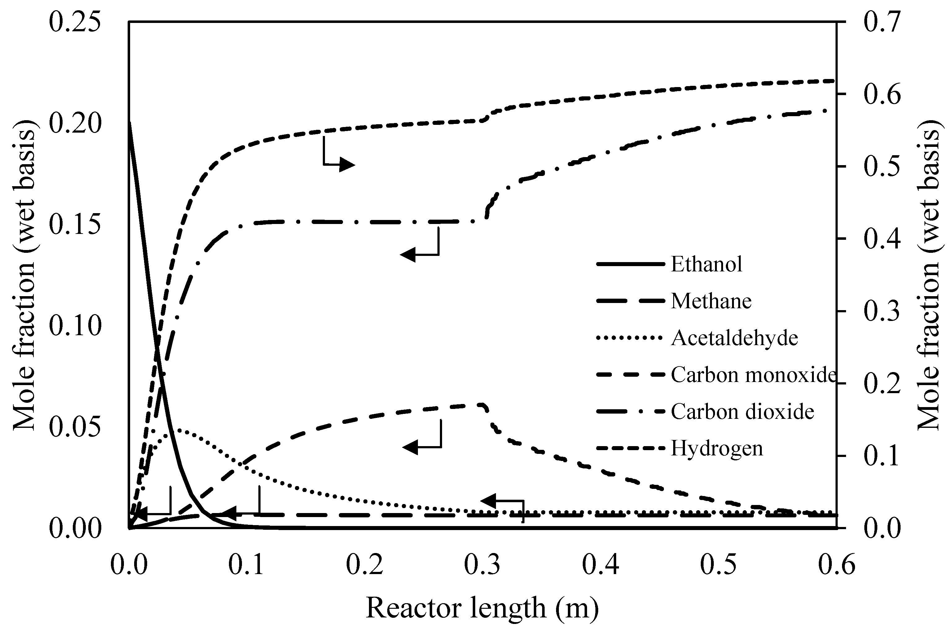
Product distribution profiles indicated in terms of mole fraction for the reformer zone and shift reactor zone along with the reactor length are shown in Figure 9. According to the length of each zone as indicated in Table 1, the reformer part was considered in the range of 0.00–0.30 m followed by the water gas shift reactor in the range of 0.30–0.60 m. For the reformer, the related reactions, Equation (R1)–(R4), produce methane, acetaldehyde, carbon dioxide and syngas. In addition, ethanol was completely consumed within 0.1 m of length. Although the acetaldehyde steam reforming reaction (Equation (R4)) could occur inside the reformer, acetaldehyde still remained in the product stream due to low reaction rate at the low reforming temperature. After 0.3 m of length, the reformed gas entered the water gas shift section. The temperature was then reduced and the water gas shift reaction shifted forward, resulting in high hydrogen production of about 61.81% by mole with the presence of impurities such as methane, acetaldehyde, carbon monoxide and carbon dioxide.
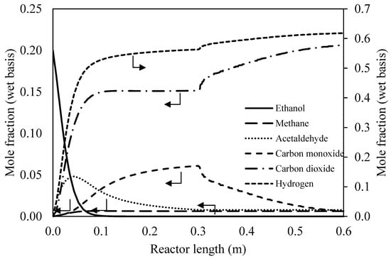
Figure 9.
Mole fraction profiles at the center along CHIRS (I).
3.2.3. Characteristics of CHIRS (II)
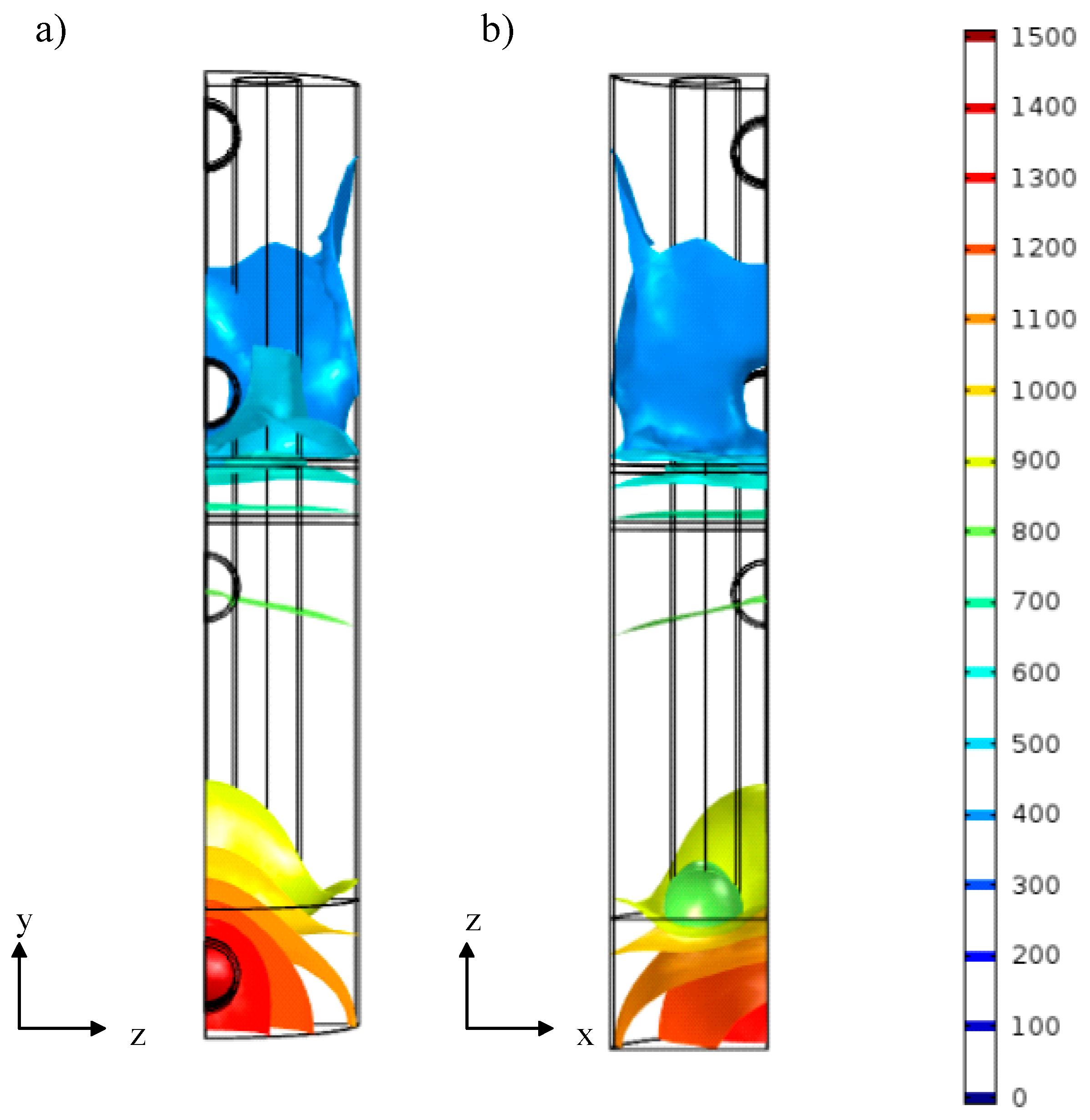
In Figure 10, the temperature contour inside the CHIRS (II) configuration in YZ and XZ planes is presented. In this case, the combusted gas flowed through the inlet at the bottom of the reactor system. The uniform temperature profile appeared in the reforming section indicating a temperature between 700 and 900 K (Figure 10a). In Figure 10b, the green area at the reformer inlet representing a temperature around 700 K was apparent. It was likely due to highly consumed energy from a high reaction rate at the inlet. In the air gap section located between the reformer and the shift reactor, the reformed gas temperature was reduced to 600 K before entering the water gas shift section. Thus, the water gas shift reaction could perform at a temperature lower than 600 K. The air gap could greatly manage the temperature gradient between the combustion and air preheating chambers. As a result, the operating temperature was controlled perfectly for both the reforming reaction at high temperature and water gas shift reaction at low temperature.
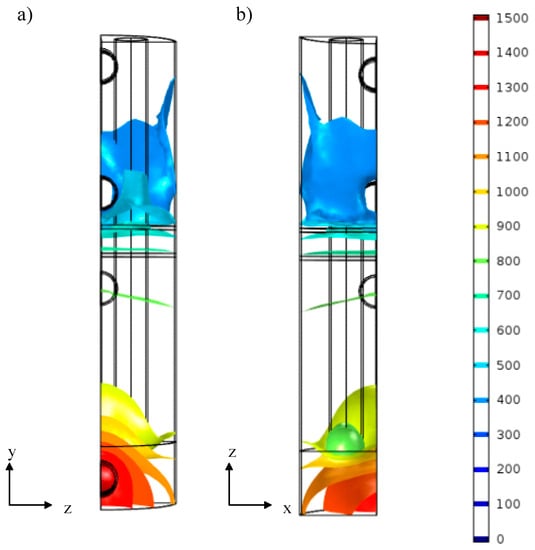
Figure 10.
Temperature profile of CHIRS (II) in the (a) YZ plane and (b) XZ direction.
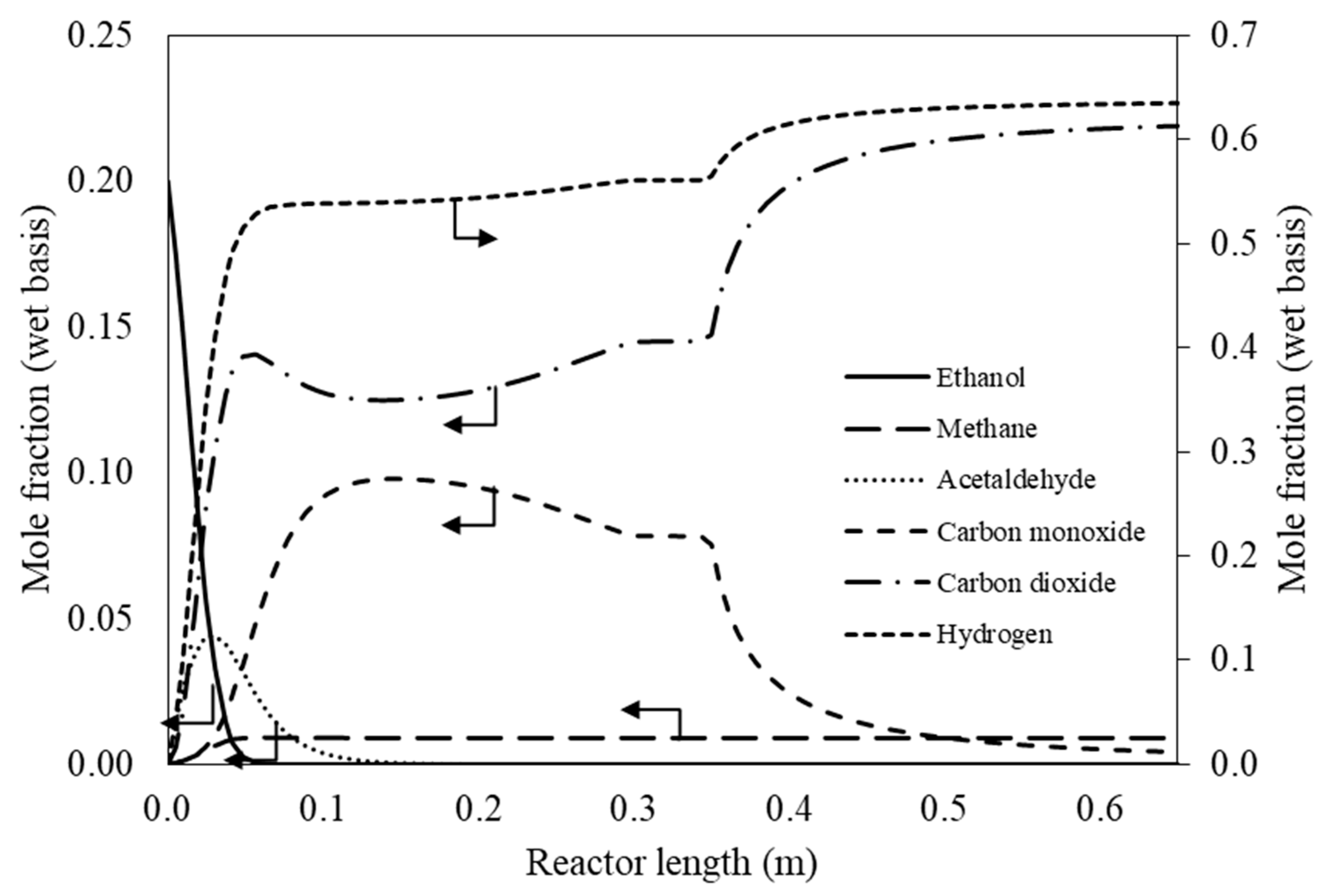
According to this configuration (Table 1), mole fraction profiles of the product stream within the reformer zone (0.00–0.30 m) followed by the air gap section (0.30–0.35 m) and the water gas shift zone (0.35–0.65 m) distributing along the reactor length are shown in Figure 11. Owing to the high reforming temperature, ethanol and acetaldehyde were totally consumed within the ethanol steam reformer section. A reverse water gas shift also occurred at the middle of the reforming section as the mole fraction of carbon dioxide was reduced. The reformed gas then flowed through the air gap section without any further reactions. Hence, the same gas composition entered the water gas shift section. Inside the shift reactor zone, the water gas shift reaction evidently took place. Carbon monoxide sharply decreased when hydrogen was noticeably increased up to 63.48% (wet basis). The product stream mainly comprised hydrogen and carbon dioxide with a very low fraction of methane and carbon monoxide.
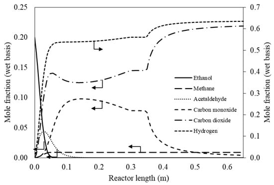
Figure 11.
Mole fraction profiles at the center along CHIRS (II).
3.2.4. Comparison in Process Performance between CHIRS (I) and CHIRS (II)
A compact heat integrated reactor system (CHIRS) combining combustor, reformer and shift reactor was designed to produce hydrogen for a stationary system with two different configurations. An overview of CHIRS (I) and CHIRS (II), including reactor volume and other reactor performance, is listed and summarized in Table 2. It was obviously found that the required volume space for CHIRS (I) was considerably higher than that for CHIRS (II), indicating the value of 72.77 and 34.11 L, respectively. The temperature gradient between reformer and shift reactor was smaller in CHIRS (I), when compared to another design. These average temperature differences between two reactors were 188.03 and 323.50 K, respectively. At a higher temperature gradient between the reformer and shift reactor, a more appropriate operating temperature with higher reformer temperature and lower shift reactor temperature led to a better yield of hydrogen. Therefore, CHIRS (II) provided higher hydrogen selectivity with an absence of acetaldehyde in the product stream. In addition, hydrogen was produced at 15.36 mmol/s, which was equivalent to 4.39 kW of hydrogen energy. The CHIRS (I) design obtained more hydrogen production, which was about 16.47 mmol/s (equivalent to 4.71 kW of hydrogen energy). However, the hydrogen production was insignificantly different. From another point of view, the volume of CHIRS (II) was half of that for CHIRS (I), whereas CHIRS (II) achieved a higher hydrogen selectivity than the other one. Moreover, the CHIRS (II) design could efficiently manage the temperature of each reactor in the combined system. Eventually, this design was recommended for hydrogen production from ethanol. However, it should be noted that when applying the hydrogen production system for PEM application, the concentration of CO in the hydrogen rich gas needs to be considered and the operating condition needs to be carefully selected to comply with the CO tolerance in PEM.

Table 2.
Process performance of CHIRS (I) and CHIRS (II).
4. Conclusions
The compact heat integrated reactor system (CHIRS) consisting of a combustor, a reformer and a water gas shift reactor was finally developed for hydrogen production from ethanol. Firstly, three reformer concepts, including SRSR, SRSR-WS, and CHIRS, relying on the level of concept development were investigated via the Aspen Plus program. According to the high process efficiency, the condition was suitably operated at a reforming temperature of 573–1073 K, reforming pressure of 1 atm and steam to ethanol ratio in the range of 3–5. The SRSR was considered as a conventional process producing a high composition of carbon monoxide with high heat loss at the outlet, resulting in low efficiency (67.50%). The SRSR-WS and CHIRS could improve the process efficiency up to 79.90% and 79.65%, respectively, due to heat integration within the system. Since the SRSR-WS had some trouble with regard to practical design and operation, the promising CHIRS design was selected to be studied in detail via COMSOL Multiphysics software. For the CHIRS design, the reformer and shift reactor were placed inside the combustion and air preheating chambers, respectively. Both chambers were integrated in the radial direction for the CHIRS (I) design and the vertical direction for the CHIRS (II) design. In the preliminary step, the CHIRS design was examined by varying the air and combusted gas flow rate to obtain a high reactor performance. It was found that the air and combusted gas flow rate was 318 and 530 L/min, respectively. The CHIRS (I) design provided a lower reformer temperature and higher shift reactor temperature, compared to the CHIRS (II) design. A temperature control in the CHIRS (II) design was better, resulting in a higher reactor performance in each section. Additionally, the CHIRS (II) design occupied half the volume of the CHIRS (I) design, whereas it provided similar hydrogen production with higher hydrogen selectivity. The CHIRS (II) design was ultimately recommended as a stationary combined reactor for hydrogen production from ethanol.
Author Contributions
Conceptualization, S.C., S.A., W.K., J.C. and T.J.; simulation, preliminary data analysis and writing—original draft preparation, T.J. and W.K.; writing—review and editing, W.K., K.O., S.W., S.C. and S.A.; funding acquisition, S.C. and S.A. All authors have read and agreed to the published version of the manuscript.
Funding
The supports from the Royal Golden Jubilee. Program from the Thailand Research Fund and Chulalongkorn University, National Metal and Materials Technology Center (MTEC), NSTDA and the “Research Chair Grant” National Science and Technology Development Agency (NSTDA) are gratefully acknowledged.
Acknowledgments
The authors would like to thank Navadol Laosiripojana from The Joint Graduate School of Energy and Environment and Pisanu Toochinda from Sirindhorn International Institute of Technology for their useful suggestions.
Conflicts of Interest
The authors declare no conflict of interest.
Nomenclature
| Specific heat at constant pressure (J kg−1 K−1) | |
| Mass diffusion coefficient of species i in mixture (m2 s−1) | |
| g | Gravity force (m/s2) |
| Heat of reaction j (J/mol) | |
| Heat of combustion of species i (kW mol−1) | |
| Thermal conductivity (W m−1 K−1) | |
| KWGS | Thermodynamics equilibrium constant (-) |
| Molar mass of species i (kg kmol−1) | |
| Mole flow rate (mol s−1) | |
| Pressure (Pa) | |
| Rate of reaction j (mol s−1 m−2) | |
| Temperature (K) | |
| Velocity (m s−1) | |
| Greek symbols | |
| Density (kg m−3) | |
| Dynamic viscosity (Pa s) | |
| Mass fraction of species i | |
References
- Liu, K.; Song, C.; Subramani, V. Hydrogen and Syngas Production and Purification Technologies; Wiley Online Library: Hoboken, NJ, USA, 2010. [Google Scholar]
- Padró, C.; Lau, F. Advances in Hydrogen Energy; Springer: Berlin/Heidelberg, Germany, 2000. [Google Scholar]
- Dincer, I.; Acar, C. Review and evaluation of hydrogen production methods for better sustainability. Int. J. Hydrog. Energy 2015, 40, 11094–11111. [Google Scholar] [CrossRef]
- Mehrpooya, M.; Moftakhari Sharifzadeh, M.M.; Rajabi, M.; Aghbashlo, M.; Tabatabai, M.; Hosseinpour, S.; Ramakrishna, S. Design of an integrated process for simultaneous chemical looping hydrogen production and electricity generation with CO2 capture. Int. J. Hydrog. Energy 2017, 42, 8486–8496. [Google Scholar] [CrossRef]
- Nikolaidis, P.; Poullikkas, A. A comparative overview of hydrogen production processes. Renew. Sustain. Energy Rev. 2017, 67, 597–611. [Google Scholar] [CrossRef]
- Nahar, G.; Mote, D.; Dupont, V. Hydrogen production from reforming of biogas: Review of technological advances and an Indian perspective. Renew. Sustain. Energy Rev. 2017, 76, 1032–1052. [Google Scholar] [CrossRef]
- Xue, Y.-P.; Yan, C.-F.; Zhao, X.-Y.; Huang, S.-L.; Guo, C.-Q. Ni/La2O3-ZrO2 catalyst for hydrogen production from steam reforming of acetic acid as a model compound of bio-oil. Korean J. Chem. Eng. 2017, 34, 305–313. [Google Scholar] [CrossRef]
- Quan, C.; Xu, S.; Zhou, C. Steam reforming of bio-oil from coconut shell pyrolysis over Fe/olivine catalyst. Energy Convers. Manag. 2017, 141, 40–47. [Google Scholar] [CrossRef]
- Nabgan, W.; Tuan Abdullah, T.A.; Mat, R.; Nabgan, B.; Gambo, Y.; Ibrahim, M.; Ahmad, A.; Jalil, A.A.; Triwahyono, S.; Saeh, I. Renewable hydrogen production from bio-oil derivative via catalytic steam reforming: An overview. Renew. Sustain. Energy Rev. 2017, 79, 347–357. [Google Scholar] [CrossRef]
- Haryanto, A.; Fernando, S.; Murali, N.; Adhikari, S. Current Status of Hydrogen Production Techniques by Steam Reforming of Ethanol: A Review. Energy Fuels 2005, 19, 2098–2106. [Google Scholar] [CrossRef]
- Ni, M.; Leung, D.Y.C.; Leung, M.K.H. A review on reforming bio-ethanol for hydrogen production. Int. J. Hydrog. Energy 2007, 32, 3238–3247. [Google Scholar] [CrossRef]
- Vaidya, P.D.; Rodrigues, A.E. Insight into steam reforming of ethanol to produce hydrogen for fuel cells. Chem. Eng. J. 2006, 117, 39–49. [Google Scholar] [CrossRef]
- Hou, T.; Zhang, S.; Chen, Y.; Wang, D.; Cai, W. Hydrogen production from ethanol reforming: Catalysts and reaction mechanism. Renew. Sustain. Energy Rev. 2015, 44, 132–148. [Google Scholar] [CrossRef]
- Sharma, Y.C.; Kumar, A.; Prasad, R.; Upadhyay, S.N. Ethanol steam reforming for hydrogen production: Latest and effective catalyst modification strategies to minimize carbonaceous deactivation. Renew. Sustain. Energy Rev. 2017, 74, 89–103. [Google Scholar] [CrossRef]
- Dou, B.; Zhang, H.; Cui, G.; Wang, Z.; Jiang, B.; Wang, K.; Chen, H.; Xu, Y. Hydrogen production and reduction of Ni-based oxygen carriers during chemical looping steam reforming of ethanol in a fixed-bed reactor. Int. J. Hydrog. Energy 2017, 42, 26217–26230. [Google Scholar] [CrossRef]
- Tripodi, A.; Compagnoni, M.; Ramis, G.; Rossetti, I. Process simulation of hydrogen production by steam reforming of diluted bioethanol solutions: Effect of operating parameters on electrical and thermal cogeneration by using fuel cells. Int. J. Hydrog. Energy 2017, 42, 23776–23783. [Google Scholar] [CrossRef]
- Castedo, A.; Uriz, I.; Soler, L.; Gandía, L.M.; Llorca, J. Kinetic analysis and CFD simulations of the photocatalytic production of hydrogen in silicone microreactors from water-ethanol mixtures. Appl. Catal. B Environ. 2017, 203, 210–217. [Google Scholar] [CrossRef]
- Wang, W.; Wang, Y.Q. Thermodynamic analysis of steam reforming of ethanol for hydrogen generation. Int. J. Energy Res. 2008, 32, 1432–1443. [Google Scholar] [CrossRef]
- Rabenstein, G.; Hacker, V. Hydrogen for fuel cells from ethanol by steam-reforming, partial-oxidation and combined auto-thermal reforming: A thermodynamic analysis. J. Power Sources 2008, 185, 1293–1304. [Google Scholar] [CrossRef]
- Wanat, E.C.; Venkataraman, K.; Schmidt, L.D. Steam reforming and water–gas shift of ethanol on Rh and Rh–Ce catalysts in a catalytic wall reactor. Appl. Catal. A Gen. 2004, 276, 155–162. [Google Scholar] [CrossRef]
- Utaka, T.; Okanishi, T.; Takeguchi, T.; Kikuchi, R.; Eguchi, K. Water gas shift reaction of reformed fuel over supported Ru catalysts. Appl. Catal. A Gen. 2003, 245, 343–351. [Google Scholar] [CrossRef]
- Amadeo, N.E.; Laborde, M.A. Hydrogen production from the low-temperature water-gas shift reaction: Kinetics and simulation of the industrial reactor. Int. J. Hydrog. Energy 1995, 20, 949–956. [Google Scholar] [CrossRef]
- Pala, L.P.R.; Wang, Q.; Kolb, G.; Hessel, V. Steam gasification of biomass with subsequent syngas adjustment using shift reaction for syngas production: An Aspen Plus model. Renew. Energy 2017, 101, 484–492. [Google Scholar] [CrossRef]
- Kaftan, A.; Kusche, M.; Laurin, M.; Wasserscheid, P.; Libuda, J. KOH-promoted Pt/Al2O3 catalysts for water gas shift and methanol steam reforming: An operando DRIFTS-MS study. Appl. Catal. B Environ. 2017, 201, 169–181. [Google Scholar] [CrossRef]
- Andisheh Tadbir, M.; Akbari, M.H. Integrated methanol reforming and oxidation in wash-coated microreactors: A three-dimensional simulation. Int. J. Hydrog. Energy 2012, 37, 2287–2297. [Google Scholar] [CrossRef]
- Grote, M.; Maximini, M.; Yang, Z.; Engelhardt, P.; Köhne, H.; Lucka, K.; Brenner, M. Experimental and computational investigations of a compact steam reformer for fuel oil and diesel fuel. J. Power Sources 2011, 196, 9027–9035. [Google Scholar] [CrossRef]
- Yin, F.; Ji, S.; Mei, H.; Zhou, Z.; Li, C. Coupling of highly exothermic and endothermic reactions in a metallic monolith catalyst reactor: A preliminary experimental study. Chem. Eng. J. 2009, 155, 285–291. [Google Scholar] [CrossRef]
- Jiwanuruk, T.; Putivisutisak, S.; Ponpesh, P.; Kositanont, C.; Tagawa, T.; Yamada, H.; Fukuhara, C.; Assabumrungrat, S. Comparison between parallel and checked arrangements of micro reformer for H2 production from methane. Chem. Eng. J. 2015, 268, 135–143. [Google Scholar] [CrossRef]
- Seo, Y.-S.; Seo, D.-J.; Seo, Y.-T.; Yoon, W.-L. Investigation of the characteristics of a compact steam reformer integrated with a water-gas shift reactor. J. Power Sources 2006, 161, 1208–1216. [Google Scholar] [CrossRef]
- Hayer, F.; Bakhtiary-Davijany, H.; Myrstad, R.; Holmen, A.; Pfeifer, P.; Venvik, H.J. Synthesis of dimethyl ether from syngas in a microchannel reactor—Simulation and experimental study. Chem. Eng. J. 2011, 167, 610–615. [Google Scholar] [CrossRef]
- Lima da Silva, A.; Malfatti, C.d.F.; Müller, I.L. Thermodynamic analysis of ethanol steam reforming using Gibbs energy minimization method: A detailed study of the conditions of carbon deposition. Int. J. Hydrogen Energy 2009, 34, 4321–4330. [Google Scholar] [CrossRef]
- Uriz, I.; Arzamendi, G.; López, E.; Llorca, J.; Gandía, L.M. Computational fluid dynamics simulation of ethanol steam reforming in catalytic wall microchannels. Chem. Eng. J. 2011, 167, 603–609. [Google Scholar] [CrossRef]
- Montero, C.; Remiro, A.; Valle, B.; Oar-Arteta, L.; Bilbao, J.; Gayubo, A.G. Origin and Nature of Coke in Ethanol Steam Reforming and Its Role in Deactivation of Ni/La2O3–αAl2O3 Catalyst. Ind. Eng. Chem. Res. 2019, 58, 14736–14751. [Google Scholar] [CrossRef]
© 2020 by the authors. Licensee MDPI, Basel, Switzerland. This article is an open access article distributed under the terms and conditions of the Creative Commons Attribution (CC BY) license (http://creativecommons.org/licenses/by/4.0/).

