A General Review of the Current Development of Mechanically Agitated Vessels


Abstract
:
1. Introduction
- -
- to disperse one immiscible liquid into another or to combine miscible liquids; to disperse solid materials in a fluid, often followed by a different process, e.g., chemical reaction, leaching or flotation; to disperse gas into a liquid, usually followed either by a chemical reaction between the liquid and the gaseous species or by absorption; to disperse a solid and gas into a liquid phase to cause reactions.
- -
- -
- the fluid properties (densities, number of phases, a viscosity [7]);
- -
- the location and mode of operation of the impeller (flow-pumping direction, clearance).
2. Mixing
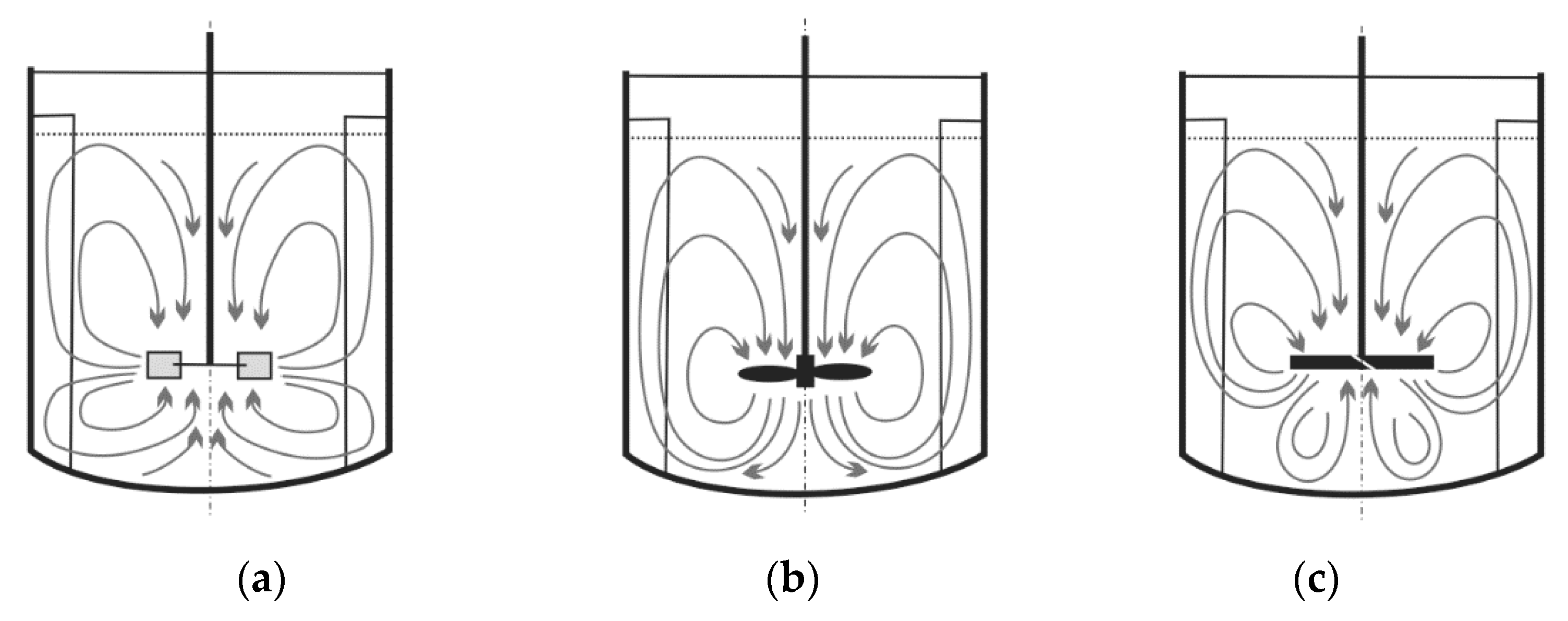
2.1. Fluid Flow
2.2. Gas-Liquid and Gas-Liquid-Liquid System
2.3. Electrical Resistance Tomography (ERT) in Gas—Liquid System
2.4. A Solid-Liquid System in a Mechanically Agitated Vessel
2.5. Solid Suspension
2.6. Solid Particle Distribution—Selected Technique
2.7. Electrical Resistance Tomography (ERT) in the Mixing of Highly Concentrated Slurries
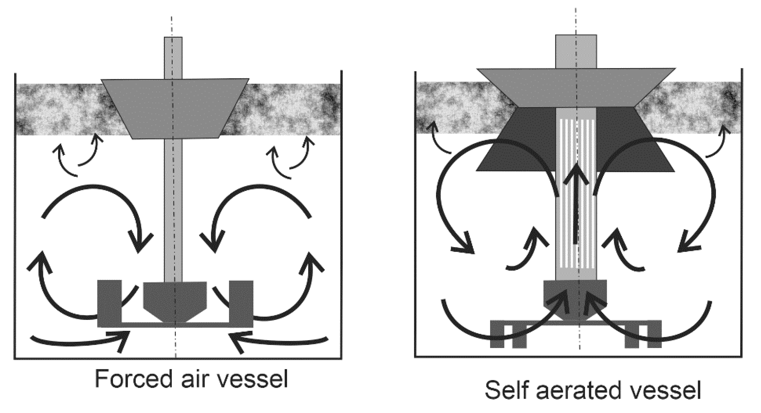
2.8. Particle in Three-Phase Reactors. Drawdown of Floating
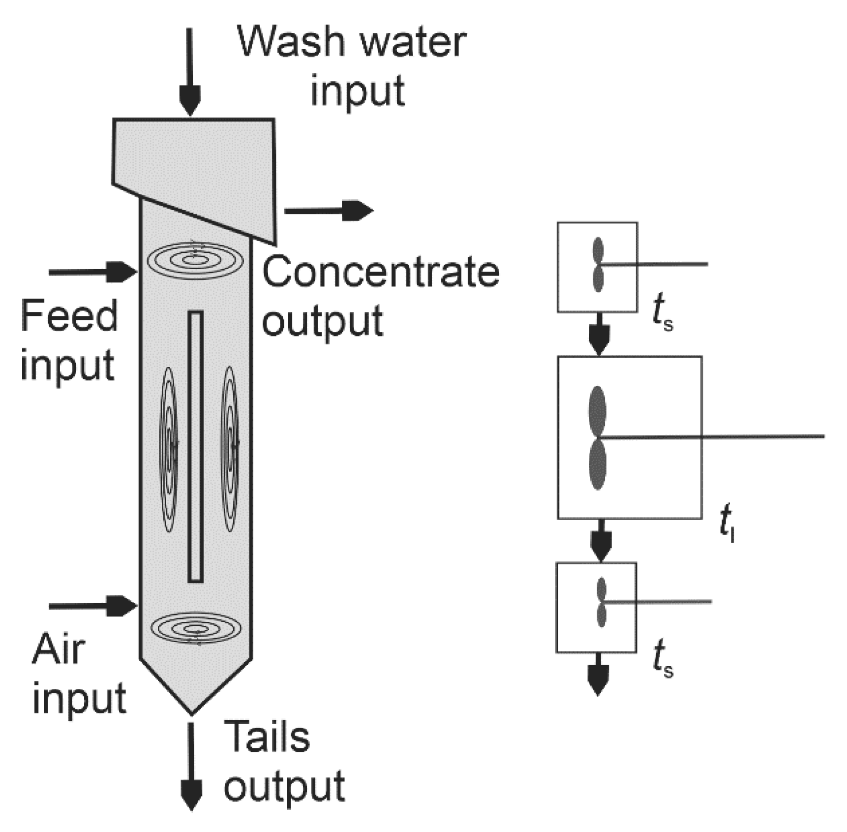
Dispersive of the Gas Phase in the Flotation Chamber
- a viscosity effect, due to damping of the turbulence by the solids [72];
2.9. Liquid-Liquid Mixture
2.10. Tomography in Mixing Process
2.11. The Effect of Impellers
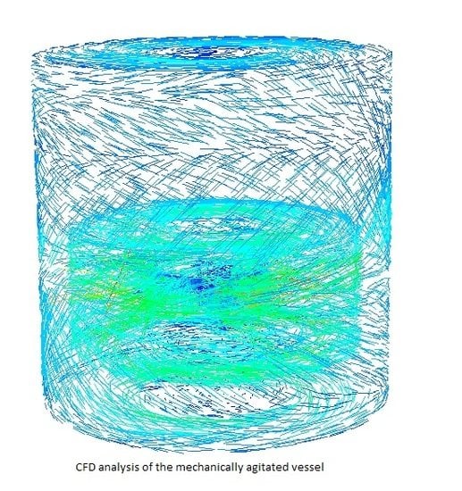
3. CFD Simulation of the Mixing Process
3.1. Gas-Liquid Phase in CFD
3.2. Mixing System Optimisation
3.3. Mass Transfer with CFD
3.4. CFD Models any Turbulence in Rotary Mixers
3.5. Impeller Rotation Modelling
4. Conclusions
Author Contributions
Funding
Conflicts of Interest
Nomenclature
| a | gas-liquid interfacial area, m2 |
| C | impeller off-bottom clearance, m |
| D | impeller diameter, m |
| dp | particle size or particle diameter, µm |
| dS | diameter of the sparger ring, m |
| H | liquid height in the vessel, m |
| T | tank diameter, m |
| V | tank volume, m3 |
| h | distance between the agitator and bottom of the vessel, m |
| A | height of the agitator blade, m |
| B | width of the agitator blade, m |
| Bo | Bond number (Bo = D2gΔρ/δ) |
| Cb | bed packing coefficient, v/v |
| Cv | solids volume concentration, v/v |
| (Cv)max | maximum solids concentration, upper limit, v/v |
| Cvb | solids packing volume concentration (v/v) |
| Fr | Froude number (Fr = DN2ρmΔρg) |
| Ga | Galileo number (Ga = D3gρmΔρ/μ2m) |
| Ho | dimensionless homogeneity index/degree |
| Jg | superficial gas rates, cm/s |
| kLa | volumetric mass transfer coefficient at the gas-liquid interface, s–1 |
| L | length of the baffle, m |
| MS | mass of solids, kg |
| MI | mixing index |
| N | impeller speed, rps |
| Ncdg | minimum impeller speed needed for complete liquid-liquid–gas dispersion |
| NH | homogenization speed, rpm |
| Njs | minimum impeller speed required for just complete off-bottom suspension of solids under un-gassed conditions, rps |
| Njsg | minimum impeller speed required for just complete off-bottom suspension of solids under gassed conditions, rps |
| P | power consumption under un-gassed condition, W |
| Pjs | agitator power for just-off-bottom solids suspension, W |
| ReG | gas Reynolds number |
| ReE | Reynolds number of turbulent eddies at Njs |
| SB | bubble surface area flux, s–1 |
| tH | homogenisation time, s |
| tm | mixing time, s |
| w | width of the baffle, m |
| Δρ | density difference between solid and liquid, kg/m3 |
| φ | gas hold-up |
| X | Zweitering solids loading, w/w |
| Xv | volume solids fractions, dim |
| εjs | agitator power per unit solids mass at the just-off-bottom solids suspension condition, W/kg |
| µ | viscosity, Pa.s |
References
- Schrimpf, M.; Esteban, J.; Rosler, T.; Vorholt, A.J.; Leitner, W. Intensified reactors for gas-liquid-liquid multiphase catalysis: From chemistry to engineering. Chem. Eng. J. 2019, 372, 917–939. [Google Scholar] [CrossRef]
- Major-Godlewska, M.; Karcz, J. Power consumption for an agitated vessel equipped with pitched blade turbine and short baffles. Chem. Zvesti. 2018, 72, 1081–1088. [Google Scholar] [CrossRef] [PubMed] [Green Version]
- Lampinga, S.R.; Zhanga, H.; Allenb, B.; Ayazi, S.P. Design of a prototype miniature bioreactor for high throughput automated bioprocessing. Chem. Eng. J. 2003, 58, 747–758. [Google Scholar] [CrossRef]
- Młynarczykowska, A.; Simone, F.S.; Demurtas, L.; Jaszczur, M. Impact of baffle geometry on the fluid motion in the stirred vessel. In Proceedings of the EFM, Experimental Fluid Mechanics Conference, Franzensbad, Czech Republic, 19–22 November 2019; pp. 321–326. [Google Scholar]
- Młynarczykowska, A.; Simone, F.S.; Demurtas, L.; Jaszczur, M. An experimental investigation on the fluid flow mixing process in agitated vessel. In Proceedings of the EFM, Experimental Fluid Mechanics Conference, Franzensbad, Czech Republic, 19–22 November 2019; pp. 321–326. [Google Scholar]
- Jaszczur, M.; Młynarczykowska, A.; Demurtas, L. An experimental and numerical analysis of the fluid flow in a mechanically agitated vessel. In Proceedings of the XII International Conference on Computational Heat, Mass and Momentum Transfer (ICCHMT 2019), Rome, Italy, 3–6 September 2019; Volume 128, p. 15. [Google Scholar]
- El-Gayar, D.A.; Konsowa, A.H.; El-Taweel, Y.A.; Farag, H.A.; Sedahmed, G.H. Intensification of the rate of diffusion controlled catalytic and electrochemical reactions in a new stirred tank reactor with a multicylindrical blade impeller. Chem. Eng. Res. and Design. 2016, 109, 607–617. [Google Scholar] [CrossRef]
- Mishra, P.; Ein-Mozaffari, F. Using computational fluid dynamics to analyze the performance of the Maxblend impeller in solid-liquid mixing operations. Int. J. Multiph. Flow 2017, 91, 194–207. [Google Scholar] [CrossRef]
- Zych, M.; Hanus, R.; Vlasák, P.; Jaszczur, M.; Petryka, L. Radiometric methods in the measurement of particle-laden flows. Powder Technol. 2017, 318, 491–500. [Google Scholar] [CrossRef]
- Hanus, R.; Zych, M.; Jaszczur, M.; Szlachta, A.; Golijanek-Jędrzejczyk, A. Signal processing in the investigation of two-phase liquid-gas flow by gamma-ray absorption. In Proceedings of the 6th International Conference on Control, Decision and Information Technologies, Paris, France, 23–26 April 2019; pp. 681–684. [Google Scholar]
- Hanus, R.; Zych, M.; Petryka, L.; Jaszczur, M.; Hanus, P. Signals features extraction in liquid-gas flow measurements using gamma densitometry. In Proceedings of the EFM15 Experimental Fluid Mechanics, Prague, Czech Republic, 17–20 November 2015. [Google Scholar]
- Mavros, P. A Review of Experimental Techniques. IChemE 2001, 79, A. [Google Scholar]
- Laakkonen, M.; Honkanen, M.; Saarenrinn, P.; Aittamaa, J. Local bubble size distributions, gas–liquid interfacial areas and gas holdups in a stirred vessel with particle image velocimetry. Chem. Eng. J. 2005, 109, 37–47. [Google Scholar] [CrossRef]
- Jardón-Pérez, E.L.; Amaro-Villeda, A.; González-Rivera, C.; Trápaga, G. Introducing the Planar Laser-Induced Fluorescence Technique (PLIF) to Measure Mixing Time in Gas-Stirred Ladles. Metall. Mater. Trans. B 2019, 50, 2121–2133. [Google Scholar]
- Lau, Y.; Deen, N.; Kuipers, J. Development of an image measurement technique for size distribution in dense bubbly flows. Chem. Eng. Sci. 2013, 94, 20–29. [Google Scholar] [CrossRef]
- Kracíka, T.; Retříčekab, T.; Mouchaa, T. Mass transfer in coalescent batch fermenters with mechanical agitation. Chem. Eng. Res. Des. 2020, 160, 587–592. [Google Scholar] [CrossRef]
- Aubin, J.; Mavros, P.; Fletcher, D.F.; Bertrand, J.; Xuereb, C. Effect of axial agitator configuration (up-pumping, down-pumping, reverse rotation) on flow patterns generated in stirred vessels. Chem. Eng. Res. Des. 2001, 79, 845–856. [Google Scholar] [CrossRef] [Green Version]
- Guida, A.; Nienow, A.W.; Barigou, M. The effects of the azimuthal position of the measurement planeon the flow parameters determined by PIV within a stirred vessel. Chem. Eng. Sci. 2010, 65, 2454–2463. [Google Scholar] [CrossRef]
- Sher, F.; Sajid, Z.; Tokay, B.; Khzouz, M.; Sadiq, H. Study of gas–liquid mixing in stirred vessel using electrical resistance tomography. Asia Pac. J. Chem. Eng. 2016, 11, 855–865. [Google Scholar] [CrossRef]
- Patel, D.; Ein-Mozaffari, F.; Mehrvar, M. Tomography images to analyze the deformation of the cavern in the continuous-flow mixing of non-Newtonian fluids. AIChE J. 2014, 60, 315–331. [Google Scholar] [CrossRef]
- Fitzpatrick, J.J.; Gloanec, F.; Michel, E.; Blondy, J.; Lauzeral, A. Application of mathematical modelling to reducing and minimising energy requirement for oxygen transfer in batch stirred tank bioreactors. Chem. Eng. 2019, 3, 1–21. [Google Scholar]
- Jaszczur, M.; Młynarczykowska, A.; Demurtas, L. Effect of impeller design on power characteristics and Newtonian fluids mixing efficiency in a mechanically agitated vessel at low Reynolds numbers. Energies 2020, 13, 640. [Google Scholar] [CrossRef] [Green Version]
- Al-Qaessi, F.; Abu-Farah, L. Prediction of Mixing Time for Miscible Liquids by CFD Simulation in Semi-batch and Batch Reactors. Eng. Appl. Comp. Fluid Mech. 2014, 3, 135–146. [Google Scholar] [CrossRef] [Green Version]
- Daryus, A.; Siswantara, A.I.; Darmawan, S.; Gunadi, G.G.R.; Camalia, R. CFD Simulation of Turbulent Flows in Proto X-3 Bioenergy Micro Gas Turbine Combustor using STD k-e and RNG k-e Model for Green Building Application. Int. J. Technol. 2016, 7, 204–211. [Google Scholar] [CrossRef] [Green Version]
- Derksen, J.J. Blending of Miscible Liquids with Different Densities Starting from a Stratified State. Comp. Fluids 2011, 50, 35–45. [Google Scholar] [CrossRef]
- Orsi, G.; Roudgar, M.; Brunazzi, E.; Galletti, C.; Mauri, R. Water–Ethanol Mixing in T-shaped Microdevices. Chem. Eng. Sci. 2013, 95, 174–183. [Google Scholar] [CrossRef]
- Montante, G.; Coroneo, M.; Pagliantic, A. Blending of miscible liquids with different densities and viscosities in static mixers. Chem. Eng. Sci. 2016, 141, 250–260. [Google Scholar] [CrossRef]
- Muharam, Y.; Kurniawan, A. Computational Fluid Dynamic Application in Scale-up of a Stirred-batch Reactor for Degumming Crude Palm Oil. Int. J. Technol. 2016, 7, 1344–1351. [Google Scholar] [CrossRef] [Green Version]
- Zhao, J.; Gao, Z.; Bao, Y. Effects of the Blade Shape on the Trailing Vortices in Liquid Flow Generated by Disc Turbines. Chin. J. Chem. Eng. 2011, 19, 232–242. [Google Scholar] [CrossRef]
- Sossa-Echeverria, J.; Taghipour, F. Computational Simulation of Mixing Flow of Shear Thinning Non-Newtonian Fluids with Various Impellers in a Stirred Tank. Chem. Eng. Proc. Process Intensif. 2015, 93, 66–78. [Google Scholar] [CrossRef]
- Rahimi, M. The Effect of Impellers Layout on Mixing Time in a Large-scale Crude Oil Storage Tank. J. Petroleum Sci. Eng. 2005, 46, 161–170. [Google Scholar] [CrossRef]
- del Pozo, D.F.; Liné, A.; Van Geem, K.M.; Le Men, C.; Nopens, I. Hydrodynamic analysis of an axial impeller in a non-Newtonian fluid through particle image velocimetry. AIChE J. 2020, 66, 6939. [Google Scholar]
- Abdulrasaq, U.K.; Ayranci, I. The effect of hydrodynamic parameters on the production of Pickering emulsions in a baffled stirred tank. AIChE J. 2019, 65, e16691. [Google Scholar]
- Tsabet, È.; Fradette, L. Effect of the properties of oil, particles, and water on the production of Pickering emulsions. Chem. Eng. Res. Des. 2015, 97, 9–17. [Google Scholar] [CrossRef]
- Sk, A.A.; Kumar, P.; Kumar, S. Effect of impeller diameter on Nusselt number in mechanically agitated vessel. Int. J. Num. Meth. Heat Fluid Flow. 2020, 30, 2225–2235. [Google Scholar] [CrossRef]
- Jafari, R.; Tanguy, P.A.; Chaouki, J. Experimental investigation on solid dispersion, power consumption and scale-up in moderate to dense solid–liquid suspensions. Chem. Eng. Res. Design 2012, 90, 201–212. [Google Scholar] [CrossRef]
- Sharma, R.N.; Shaikh, A.A. Solids suspension in stirred tanks with pitched blade turbines. Chem. Eng. Sci. 2003, 58, 2123–2140. [Google Scholar] [CrossRef]
- Ayranci, I.; Machado, M.B.; Madej, A.M.; Derksen, J.J.; Nobes, D.S.; Kresta, S.M. Effect of geometry on the mechanisms for off-bottom solids suspension in a stirred tank. Chem. Eng. Sci. 2012, 79, 163–176. [Google Scholar] [CrossRef]
- Ayranci, I.; Ng, T.; Etchells, A.W.; Kresta, S.M. Prediction of just suspended speed for mixed slurries at high solids loadings. Chem. Eng. Res. Des. 2013, 91, 227–233. [Google Scholar] [CrossRef]
- Bakker, A.; Laroche, R.D.; Wang, M.H.; Calabrese, R.V. Sliding mesh simulation of laminar flow in stirred reactors. Trans. Inst. Chem. Eng. Res. Des. 1997, 75, 42–44. [Google Scholar] [CrossRef]
- Ibrahim, S.; Wong, S.D.; Baker, I.F.; Zamzam, Z.; Sato, M.; Kato, Y. Influence of geometry and slurry properties on fine particles suspension at high loadings in a stirred vessel. Chem. Eng. Res. Des. 2015, 94, 324–336. [Google Scholar] [CrossRef]
- Ibrahim, S.; Nienow, A.W. The effect of viscosity on particle suspension in an aerated stirred vessel with different impellers and bases. Chem. Eng. Commun. 2009, 197, 434–454. [Google Scholar]
- Ibrahim, S.; Nienow, A.W. Comparing impeller performance for solid suspension in the transitional flow regime with Newtonian fluids. Chem. Eng. Res. Des. 1999, 77, 721–727. [Google Scholar] [CrossRef]
- Ibrahim, S.; Nienow, A.W. Particle suspension in the turbulent regime-The effect of impeller type and impeller/vessel configuration. Chem. Eng. Res. Des. 1996, 74, 679–688. [Google Scholar]
- Ayranci, I.; Kresta, S.M. Design rules for suspending concentrated mixtures of solids in stirred tanks. Chem. Eng. Res. Des. 2011, 89, 1961–1971. [Google Scholar] [CrossRef]
- Ayranci, I.; Kresta, S.M. Critical analysis of Zwietering correlation for solids suspension in stirred tanks. Chem. Eng. Res. Des. 2013, 92, 413–422. [Google Scholar] [CrossRef]
- Hosseini, S.; Patel, D.; Ein-Mozaffari, F.; Mehrvar, M. Study of solid–liquid mixing in agitated tanks through electrical resistance tomography. Chem. Eng. Sci. 2010, 65, 1374–1384. [Google Scholar] [CrossRef]
- Hosseini, S.; Patel, D.; Ein-Mozaffari, F.; Mehrvar, M. Study of solid-liquid mixing in agitated tanks through computational fluid dynamics modeling. Ind. Eng. Chem. Res. 2010, 49, 4426–4435. [Google Scholar] [CrossRef]
- Harrison, S.T.; Stevenson, R.; Cilliers, J.J. Assessing solids concentration homogeneity in Rushton-agitated slurry reactors using electrical resistance tomography (ERT). Chem. Eng. Sci. 2012, 71, 392–399. [Google Scholar] [CrossRef]
- Tamburini, A.; Cipollina, A.; Micale, G.; Brucato, A. Dense solid-liquid suspensions in top-covered unbaffled stirred vessels. Chem. Eng. Trans. 2011, 24, 1441–1446. [Google Scholar] [CrossRef]
- Tamburini, A.; Cipollina, A.; Micale, G.; Brucato, A.; Ciofalo, M. CFD simulations of dense solid-liquid suspensions inbaffled stirred tanks: Prediction of suspension curves. Chem. Eng. J. 2011, 178, 324–341. [Google Scholar] [CrossRef]
- Tamburini, A.; Cipollina, A.; Micale, G.; Brucato, A. Measurements of Njs and power requirements in unbaffled bioslurry reactors. Chem. Eng. Trans. 2012, 27, 343–348. [Google Scholar]
- Tamburini, A.; Brucato, A.; Busciglio, A.; Cipollina, A.; Grisafi, F.; Micale, G.; Scargiali, F.; Vella, G. Solid-liquid suspensions in top-covered unbaffled vessels: Influence of particle size, liquid viscosity, impeller size, and clearance. Ind. Eng. Chem. Res. 2014, 53, 9587–9599. [Google Scholar] [CrossRef]
- Lamberto, D.J.; Alvarez, M.M.; Muzzio, F.J. Experimental and computational investigation of the laminar flow structure in a stirred tank. Chem. Eng. Sci. 1999, 54, 919–942. [Google Scholar] [CrossRef]
- Wu, J.; Zhu, Y.G.; Pullum, L. Suspension of high concentration slurry. AIChE 2002, 48, 1349–1352. [Google Scholar] [CrossRef]
- Kraume, M. Mixing Time in Stirred Suspensions. Chem. Eng. Technol. 1992, 15, 313–318. [Google Scholar] [CrossRef]
- Bujalski, W.; Takenaka, K.; Paolilni, S.; Jahoda, M.; Paglianti, A.; Takahashi, A.; Nienow, A.W.; Etchells, A.W. Suspensions and liquid homogenisation in high solids concentration stirred chemical reactors. Trans. IChemE 1999, 77, 241–247. [Google Scholar] [CrossRef]
- Kuzmani, N.; Zaneti, R.; Akrap, M. Impact of floating suspended solids on the homogenisation of the liquid phase in dual-impeller agitated vessel. Chem. Eng. Process. 2008, 47, 663–669. [Google Scholar] [CrossRef]
- Mishra, P.; Ein-Mozaffari, F. Using tomograms to assess the local solid concentrations in a slurry reactor equipped with a Maxblend impeller. Powder Technol. 2016, 301, 701–712. [Google Scholar] [CrossRef]
- Kazemzadeh, A.; Ein-Mozaffari, F.; Lohi, A. Effect of impeller type on mixing of highly concentrated slurries of large particles. Particuology 2020, 50, 88–99. [Google Scholar] [CrossRef]
- Kazemzadeh, A.; Ein-Mozaffari, F.; Lohi, A. Hydrodynamics of solid and liquid phases in a mixing tank containing high solid loading slurry of large particles via tomography and computational fluid dynamics. Powder Technol. 2020, 360, 635–648. [Google Scholar] [CrossRef]
- Kazemzadeh, A.; Ein-Mozaffari, F.; Lohi, A.; Pakzad, L. Effect of the rheological properties on the mixing of Herschel-Bulkley fluids with coaxial mixers: Applications of tomography, CFD, and response surface methodology. Can. J. Chem. Eng. 2016, 94, 2394–2406. [Google Scholar] [CrossRef]
- Kazemzadeh, A.; Ein-Mozaffari, F.; Lohi, A.; Pakzad, L. Investigation of hydrodynamic performances of coaxial mixers in agitation of yield pseudoplastic fluids: Single and double central impellers in combination with the anchor. Chem. Eng. J. 2016, 294, 417–430. [Google Scholar] [CrossRef]
- Kazemzadeh, A.; Ein-Mozaffari, F.; Lohi, A.; Pakzad, L. A new perspective in the evaluation of the mixing of biopolymer solutions with different coaxial mixers comprising of two dispersing impellers and a wall scraping anchor. Chem. Eng. Res. Des. 2016, 114, 202–219. [Google Scholar] [CrossRef]
- Kazemzadeh, A.; Ein-Mozaffari, F.; Lohi, A.; Pakzad, L. Intensification of mixing of shear-thinning fluids possessing yield stress with the coaxial mixers composed of two different central impellers and an anchor. Chem. Eng. Process. Process Intensif. 2017, 111, 101–114. [Google Scholar] [CrossRef]
- Vadlakonda, B.; Mangadoddy, N. Hydrodynamic study of three-phase flow in column flotation using electrical resistance tomography coupled with pressure transducers. Sep. Purif. Technol. 2018, 203, 274–288. [Google Scholar] [CrossRef]
- Windows-Yule, C.R.K.; Hart-Villamil, R.; Ridout, T.; Kokalova, T.; Nogueira-Filho, C.J. Positron Emission Particle Tracking for Liquid-Solid Mixing in Stirred Tanks. Chem. Eng. Tech. 2020. [Google Scholar] [CrossRef]
- Lassaigne, M.M.; Bruno Blais, B.; Fradette, L.; Bertrand, F. Experimental investigation of the mixing of viscous liquids and non-dilute concentrations of particles in a stirred tank. Chem. Eng. Res. Des. 2016, 108, 55–68. [Google Scholar] [CrossRef]
- Bonga, Y.E.; Eshtiaghia, N.; Wub, J.; Parthasarathy, R. Optimum solids concentration for solids suspension and solid–liquid mass transfer in agitated vessels. Chem. Eng. Res. Des. 2015, 100, 148–156. [Google Scholar] [CrossRef]
- Grenville, R.K.; Giacomelli, J.J.; Brown, D.A.R. Suspension of solid particles in vessels agitated by Rushton turbine impellers. Chem. Eng. Res. Des. 2016, 109, 730–733. [Google Scholar] [CrossRef]
- Wood, T.; Simmons, M.; Greenwood, J.H.; Hugh, R.W.; Stitt, E. Concentrated Slurry Formation via Drawdown and Incorporation of Wettable Solids in a Mechanically Agitated Vessel. AIChE J. 2018, 64, 1885–1895. [Google Scholar] [CrossRef] [Green Version]
- Cooke, M.; Heggs, J.P.; Rodgers, T.L. The effect of solids on the dense phase gas fraction and gas–liquid mass transfer at conditions close to the heterogeneous regime in a mechanically agitated vessel. Chem. Eng. Res. Des. 2008, 86, 869–882. [Google Scholar] [CrossRef]
- Wang, S.; Boger, D.V.; Wu, J. Energy efficient solids suspension in an agitated vessel–water slurry. Chem. Eng. Sci. 2012, 74, 233–243. [Google Scholar] [CrossRef]
- Major-Godlewska, M.; Karcz, J. Process characteristics for gas-liquid system agitated in a vessel equipped with a turbine impeller and tubular baffles. Chem. Pap. 2011, 65, 132–138. [Google Scholar] [CrossRef]
- Scargiali, F.; D’Orazio, A.; Grisafi, F.; Brucato, A. Modelling and simulation of gas-liquid hydrodynamics in mechanically stirred tanks. Chem. Eng. Res. Des. 2007, 85, 637–646. [Google Scholar] [CrossRef]
- Adamiak, R.; Karcz, J. Effects of type and number of impellers and liquid viscosity on the power characteristics of mechanically agitated gas-liquid systems. Chem. Pap. 2007, 61, 16–23. [Google Scholar] [CrossRef]
- Yianatos, J.; Contreras, F.; Diaz, F. Gas hold-up and RTD measurement in an industrial flotation cell. Miner. Eng. 2010, 23, 125–130. [Google Scholar] [CrossRef]
- Cudak, M. Hydrodynamic characteristics of mechanically agitated air - aqueous sucrose solutions. Chem. Process Eng. 2014, 35, 97–107. [Google Scholar] [CrossRef] [Green Version]
- Cudak, M.; Kiełbus-Rąpała, A.; Major-Godlewska, M.; Karcz, J. Influence of different factors on momentum transfer in mechanically agitated multiphase systems. Chem. Proc. Eng. 2016, 37, 41–53. [Google Scholar] [CrossRef] [Green Version]
- Khalili, F.; Jafari Nasr, M.R.; Kazemzadeh, A.; Ein-Mozaffari, F. Hydrodynamic performance of the ASI impeller in an aerated bioreactor containing the biopolymer solution through tomography and CFD. Chem. Eng. Res. Des. 2017, 125, 190–203. [Google Scholar] [CrossRef]
- Babaei, R.; Bonakdarpour, B.; Ein-Mozaffari, F. Analysis of gas-phase characteristics and mixing performance in an activated sludge bioreactor using electrical resistance tomography. Chem. Eng. J. 2015, 279, 874–884. [Google Scholar] [CrossRef]
- Babaei, R.; Bonakdarpour, B.; Ein-Mozaffari, F. The use of electrical resistance tomography for the characterization of gas holdup inside a bubble column bioreactor containing activated sludge. Chem. Eng. J. 2015, 268, 260–269. [Google Scholar] [CrossRef]
- Kazemzadeh, A.; Elias, C.; Tamer, M.; Ein-Mozaffari, F. Hydrodynamic performance of a single-use aerated stirred bioreactor in animal cell culture: Applications of tomography, dynamic gas disengagement (DGD), and CFD. Bioprocess Biosyst. Eng. 2018, 41, 679–695. [Google Scholar] [CrossRef]
- Hashemi, N.; Ein-Mozaffari, F.; Upreti, S.R.; Hwang, D.K. Analysis of mixing in an aerated reactor equipped with the coaxial mixer through electrical resistance tomography and response surface method. Chem. Eng. Res. Des. 2016, 109, 734–752. [Google Scholar] [CrossRef]
- Hashemi, N.; Ein-Mozaffari, F.; Upreti, S.R.; Hwang, D.K. Experimental investigation of the bubble behavior in an aerated coaxial mixing vessel through electrical resistance tomography (ERT). Chem. Eng. J. 2016, 289, 402–412. [Google Scholar] [CrossRef]
- Sardeshpande, V.M.; Suraj Gupta, S.; Ranade, V.V. Electrical resistance tomography for gas holdup in a gas-liquid stirred tank reactor. Chem. Eng. Sci. 2017, 170, 476–490. [Google Scholar] [CrossRef] [Green Version]
- Pakzad, L.; Ein-Mozaffari, F.; Chan, F. Using electrical resistance tomography and computational fluid dynamics modeling to study the formation of cavern in the mixing of pseudoplastic fluids possessing yield stress. Chem. Eng. Sci. 2008, 63, 2508–2522. [Google Scholar] [CrossRef]
- Perumala, S.V.; Jayantib, S.; Nagarajana, K. Effect of impeller type and density difference on the draw down of low density microspheres. Chem. Eng. Res. Design 2015, 104, 571–578. [Google Scholar] [CrossRef]
- Mahdavi, I.; Janamiri, R.; Sinkakarimi, A.; Safdari, M.; Sedaghat, M.H.; Zamani, A.; Hoseini, A.; Karimi, M. Interface Location in Single Phase Stirred Tanks. Int. J. Chem. Mol. Eng. 2013, 7, 6. [Google Scholar]
- Ramajo, D.; Corzo, S.; Nigro, N.A. Coupled Model for Two-Phase Simulation of a Heavy Water Pressure Vessel Reactor. Int. J. Phys. Math. Sci. 2015, 9, 11. [Google Scholar]
- Perwitasari, D.S.; Edahwati, L.; Sutiyono, S.; Karaman, N.; Jamari, J.; Muryanto, S.; Bayuseno, P.A. Effect of calcium additive on the crystallization of struvite. In MATEC Web of Conferences, Proceedings of the 3rd Bali International Seminar on Science and Technology (BISSTECH2015), Bali, Indonesia, 15–17 October 2015; EDP Science: Strasbourg, France, 2016; Volume 58, p. 01007. [Google Scholar]
- Fitzpatrick, J.J.; Gloanec, F.; Michael, E. Insights from Mathematical Modelling into Process Control of Oxygen Transfer in Batch Stirred Tank Bioreactors for Reducing Energy Requirement. Chem. Eng. 2020, 4, 34. [Google Scholar] [CrossRef]
- Szczerkowska, S.; Wiertel-Pochopien, A.; Zawala, J.; Larsenc, E.; Kowalczuk, B.P. Kinetics of froth flotation of naturally hydrophobic solids with different shapes. Miner. Eng. 2018, 121, 90–99. [Google Scholar] [CrossRef]
- Šulc, R.; Ditl, P. The effect of process conditions on the flocculation process occurring in an agitated vessel. Polish J. Chem. Tech. 2012, 14, 88–96. [Google Scholar] [CrossRef] [Green Version]
- Kasat, R.G.; Pandit, B.A. Review on Mixing Characteristics in Solid-Liquid and Solid-Liquid-Gas Reactor Vessels. Can. J. Chem. Eng. 2005, 83, 618–643. [Google Scholar]
- Abdel-Aziz, M.H. Solid–liquid mass transfer in relation to diffusion controlled corrosion at the outer surface of helical coils immersed in agitated vessels. Chem. Eng. Res. Design 2013, 91, 43–50. [Google Scholar] [CrossRef]
- Sedahmed, G.H.; Abdo, M.S.; Kamal, M.A.; Fadaly, O.A.; Osman, H.M. A mass transfer study of the electropolishing of metals in mechanically agitated vessels. Int. Com. Heat Mass Transf. 2001, 28, 257–265. [Google Scholar] [CrossRef]
- Petrícek, R.; Moucha, T.; Kracíka, T.; Haidl, J. Power consumption prediction in a coalescent liquid in mechanically agitated gas–liquid reactors. Chem. Eng. Res. Design 2019, 147, 644–647. [Google Scholar]
- Petrícek, R.; Moucha, T.; Rejl, J.F.; Valenz, L.; Haidl, J. Volumetric mass transfer coefficient in the fermenter agitated by Rushton turbines of various diameters in viscous batch. Int. J. Heat Mass Trans. 2017, 115, 856–866. [Google Scholar]
- Petrícek, R.; Moucha, T.; Kracíka, T.; Rejl, J.F.; Valenz, L.; Haidl, J. Volumetric mass transfer coefficient in the fermenter agitated by Rushton turbines of various diameters in coalescent batch. Int. J. Heat Mass Trans. 2019, 130, 968–977. [Google Scholar]
- Petrícek, R.; Moucha, T.; Rejl, J.F.; Valenz, L.; Haidl, J.; Cmelíková, T. Volumetric mass transfer coefficient, power input and gas hold-up in viscous liquid in mechanically agitated fermenters. Measurements and scale-up. Int. J. Heat Mass Trans. 2018, 124, 1117–1135. [Google Scholar]
- Petrícek, R.; Moucha, T.; Rejl, J.F.; Valenz, L.; Haidl, J.; Cmelíková, T. Gas-liquid-solid volumetric mass transfer coefficient and impeller power consumptions for industrial vessel design. Int. J. Heat Mass Trans. 2018, 121, 653–662. [Google Scholar]
- Labík, L.; Moucha, T.; Petrícek, R.; Rejl, J.F.; Valenz, L.; Haidl, J. Volumetric mass transfer coefficient in viscous liquid in mechanically agitated fermenters. Measurement and correlation. Chem. Eng. Sci. 2017, 170, 451–463. [Google Scholar] [CrossRef]
- Loubière, C.; Delafosse, A.; Guedon, E.; Chevalot, I.; Toye, D.; Olmos, E. Dimensional analysis and CFD simulations of microcarrier ‘just-suspended’ state in mesenchymal stromal cells bioreactors. Chem. Eng. Sci. 2019, 203, 464–474. [Google Scholar] [CrossRef]
- Drewer, G.R.; Ahmed, N.; Jameson, G.J. An Optimum Concentration for the Suspension of Solids in Stirred Vessels. In Mixing and Crystallization; Academic Publishers: Kluwer, The Netherlands, 2000. [Google Scholar]
- Kasat, G.R.; Khopkar, A.R.; Ranade, V.V.; Pandit, A.B. CFD simulation of liquid-phase mixing in solid-liquid stirred reactor. Chem. Eng. Sci. 2008, 63, 3877–3885. [Google Scholar] [CrossRef]
- Wu, J.; Nguyen, B.; Graham, L. Mixing Intensification for the Mineral Industry. Can. J. Chem. Eng. 2010, 88, 447–454. [Google Scholar] [CrossRef]
- Wang, S.; Parthasarathy, R.; Bong, Y.E.; Wu, J.; Slatter, P. Suspension of Ultrahigh Concentration Solids in an Agitated Vessel. AIChE J. 2012, 58, 1291–1302. [Google Scholar] [CrossRef]
- Cudak, M.; Karcz, J.; Major-Godlewska, M. Problems of Heat Transfer in Agitated Vessels. In Practical Aspects of Chemical Engineering; Springer: Cham, Switzerland, 2018; pp. 35–50. [Google Scholar]
- Suchecki, W. Investigation of the sedimentation process using flow visualization methods. Chem. Proc. Eng. 2019, 40, 223–233. [Google Scholar]
- Tamburini, A.; Cipollina, A.; Micale, G.; Brucato, A. Particle distribution in dilute solid liquid unbaffled tanks via a novel laser sheet and image analysis based technique. Chem. Eng. Sci. 2013, 87, 341–358. [Google Scholar] [CrossRef]
- Zheng, Y.; Zhang, Q. Simultaneous measurement of gas and solid holdups in multiphase systems using ultrasonic technique. Chem. Eng. Sci. 2004, 59, 3505–3514. [Google Scholar] [CrossRef]
- Chang, J.S.; Ichikawa, Y.; Irons, G.A.; Morala, E.C.; Wan, P.T. Void fraction measurement by an ultrasonic transmission technique in bubbly gas–liquid two-phase flow. In Measuring Techniques in Gas–Liquid Two-Phase Flows; Delhaye, J.M., Cognet, G., Eds.; Springer: New York, NY, USA, 1984. [Google Scholar]
- Bałyga, J.; Jasińska, M. Energetic Efficiency of Mixing and Mass Transfer in Single Phase and Two-Phase Systems. Chem. Proc. Eng. 2017, 38, 79–96. [Google Scholar] [CrossRef] [Green Version]
- Khalili, F.; JafariNasr, M.R.; Kazemzadeh, A.; Ein-Mozaffari, F. Analysis of gas holdup and bubble behavior in a biopolymer solution inside a bioreactor using tomography and dynamic gas disengagement techniques. J. Chem. Technol. Biotechnol. 2018, 93, 340–349. [Google Scholar] [CrossRef]
- Kazemzadeh, A.; Ein-Mozaffari, F.; Lohi, A. Mixing of highly concentrated slurries of large particles: Applications of electrical resistance tomography (ERT) and response surface methodology (RSM). Chem. Eng. Res. Des. 2019, 143, 226–240. [Google Scholar] [CrossRef]
- Patel, D.; Ein-Mozaffari, F.; Mehrvar, M. Using Tomography to Characterize the Mixing of Non-Newtonian Fluids with a Maxblend Impeller. Chem. Eng. Tech. 2013, 36, 687–695. [Google Scholar] [CrossRef]
- Mishra, P.; Ein-Mozaffari, F. Critical review of different aspects of liquid-solid mixing operations. Rev. Chem. Eng. 2020, 36, 555–592. [Google Scholar] [CrossRef]
- Vinnett, Z.; Contreras, F.; Yianatos, J. Gas dispersion pattern in mechanical flotation cells. Miner. Eng. 2012, 26, 80–85. [Google Scholar] [CrossRef]
- Yianatos, J.B. Fluid flow and kinetic modelling in flotation related processes Columns and Mechanically Agitated Cells—A Review. Trans. IChemE Part A Chem. Eng. Res. Des. 2007, 85, 1591–1603. [Google Scholar] [CrossRef]
- Trahar, W.J.; Warren, L.J. The flotability of very fine particles—A review. Int. J. Miner. Process. 1976, 3, 103–131. [Google Scholar] [CrossRef]
- Brożek, M.; Młynarczykowska, A. Probability of detachment of particle determined according to the stochastic model of flotation kinetics. Physicochem. Probl. Min. Process. 2010, 44, 23–34. [Google Scholar]
- Brożek, M.; Młynarczykowska, A. The relation between the dispersive model of the particle and the distribution of permanent adhesion rate constant in the coal flotation process. Min. Res. Manag. 2008, 24, 63–82. [Google Scholar]
- Koh, P.T.L.; Manickam, M.; Schwarz, M.P. CFD simulation of bubble-particle collisions in mineral flotation cells. Miner. Eng. 2000, 13, 1455–1463. [Google Scholar] [CrossRef]
- Saramak, D.; Krawczykowska, A.; Młynarczykowska, A. Effects of high pressure ore grinding on the efficiency of flotation operations. Arch. Min. Sci. 2014, 59, 731–740. [Google Scholar] [CrossRef] [Green Version]
- Brożek, M.; Młynarczykowska, A. Application of the stochastic model for analysis of flotation kinetics with coal as an example. Physicochem. Probl. Miner. Process. 2006, 40, 31–44. [Google Scholar]
- Finch, J.A.; Dobby, G.S. Column Flotation, 1st ed.; Pergamon Press: London, UK, 1990. [Google Scholar]
- Brożek, M.; Młynarczykowska, A. The distribution of air bubble size in the pneumo-mechanical flotation machine. Arch. Min. Sci. 2012, 57, 729–740. [Google Scholar]
- Młynarczykowska, A.; Nyrek, A.; Oleksik, K. Analysis of the gas phase in flotation process. Experimental determination of the volume of air bubbles in the pneumo-mechanical flotation machine. J. Pol. Min. Eng. Soc. 2015, 16, 181–188. [Google Scholar]
- Młynarczykowska, A.; Oleksik, K. Analysis of the gas phase in flotation process. Pt. 2, Empirical functions of occurrence frequency of tested parameters. J. Pol. Min. Eng. Soc. 2017, 18, 257–262. [Google Scholar]
- Busciglio, A.; Grisafi, F.; Scargiali, F.; Brucato, A. On the measurement of local gas hold-up, interfacial area and bubble size distribution in gas–liquid contactors via light sheet and image analysis: Imaging technique and experimental results. Chem. Eng. Sci. 2013, 102, 551–566. [Google Scholar] [CrossRef]
- Pal, R.; Masliyah, J. Flow characteristics of a flotation column. Can. J. Chem. Eng. 1990, 29, 97–103. [Google Scholar]
- Xu, M.; Finch, J.A.; Uribe-Salas, A. Maximum gas and bubble surface rates in flotation columns. Int. J. Miner. Process. 1991, 32, 233–250. [Google Scholar] [CrossRef]
- Langberg, D.E.; Jameson, G.J. The coexistence of the froth and liquid phases in a flotation column. Chem. Eng. Sci. 1999, 247, 4345–4355. [Google Scholar] [CrossRef]
- Brożek, M.; Młynarczykowska, A. Analysis of kinetics models of batch flotation. Physicochem. Probl. Min. Process. 2007, 41, 51–65. [Google Scholar]
- Basavarajappa, M.; Miskovic, S. Investigation of gas dispersion characteristics in stirred tank and flotation cell using a corrected CFD-PBM quadrature-based moment method approach. Miner. Eng. 2016, 95, 161–184. [Google Scholar] [CrossRef]
- Yianatos, J.B.; Henríquez, F. Boundary conditions for gas rate and bubble size at the pulp-froth interface in flotation equipment. Miner. Eng. 2007, 20, 625–628. [Google Scholar] [CrossRef]
- Pyke, B.; Duan, J.; Fornasiero, D.; Ralston, J. From turbulence and collision to attachment and detachment: A general flotation model. In Fundamentals to Applications, Proceedings of the Strategic Conference Flotation and Flocculation, Kailua-Kona, Hawaii, 28 July–2 August 2002; Ralston, J., Miller, J., Rubio, J., Eds.; Snap Printing: Adelaide, Australia, 2003; pp. 77–89. [Google Scholar]
- Koh, P.T.L.; Schwarz, M.P. CFD modelling of bubble–particle attachments in flotation cells. Miner. Eng. 2006, 19, 619–626. [Google Scholar] [CrossRef]
- Bloom, F.; Heindel, T.J. On the structure of collision and detachment frequencies in flotation models. Chem. Eng. Sci. 2002, 57, 2467–2473. [Google Scholar] [CrossRef]
- Musiał, M.; Karcz, J.; Cudak, M. Numerical analysis of momentum transfer processes in a mechanically agitated Air—Biophase—Liquid system. Chem. Proc. Eng. 2017, 38, 465–475. [Google Scholar] [CrossRef] [Green Version]
- Koh, P.T.L.; Schwarz, M.P. CFD modeling of bubble particle collision rates and efficiencies in a flotation cell. Miner. Eng. 2003, 16, 1055–1059. [Google Scholar] [CrossRef]
- Jaszczur, M.; Młynarczykowska, A.; Hanus, R. An analysis of the velocity field distribution inside the flotation chamber. J. Phys. Conf. Ser. 2016, 745, 032121. [Google Scholar] [CrossRef]
- Finch, J.A. Column flotation: A selected review—Part IV: Novel flotation devices. Miner. Eng. 1995, 8, 587–602. [Google Scholar] [CrossRef]
- Evansa, G.M.; Doroodchia, E.; Laneb, G.L.; Koh, P.T.L.; Schwarz, M.P. Mixing and gas dispersion in mineral flotation cells. Chem. Eng. Res. Des. 2008, 86, 1350–1362. [Google Scholar] [CrossRef]
- Deglon, D.A.; Meyer, C.J. CFD modelling of stirred tanks: Numerical considerations. Miner. Eng. 2006, 19, 1059–1068. [Google Scholar] [CrossRef]
- Lane, G.L.; Schwarz, M.P.; Evans, G.M. Numerical modeling of gas–liquid flow in stirred tanks. Chem. Eng. Sci. 2005, 60, 2203–2214. [Google Scholar] [CrossRef]
- Smith, J.M. Dispersion of gases in liquids: The hydrodynamics of gas dispersion in low viscosity liquids. In Mixing of Liquids by Mechanical Agitation; Ulbrecht, J.J., Patterson, G.K., Eds.; Gordon and Breach: New York, NY, USA, 1985; pp. 139–201. [Google Scholar]
- Cooke, M.; Heggs, P.J.; Eaglesham, A.; Housley, D. Bubble studies under cold and boiling conditions using dynamic gas disengagement coupled with video and photographic techniques. In Proceedings of the Eurotherm, 12th International Heat Transfer Conference, Grenoble, France, 18–23 August 2002; Volume 71, pp. 95–101. [Google Scholar]
- Ozcan, O.; Calimli, A.; Berber, B.; Oguz, H. Effect of inert solid particles at low concentrations on gas–liquid mass transfer in mechanically agitated tanks. Chem. Eng. Sci. 2000, 55, 2737–2740. [Google Scholar] [CrossRef]
- Gentile, F.; Oleschko, H.; Veverka, P.; Machon, V.; Paglainti, A.; Bujalski, W.; Etchells, A.W.; Nienow, A.W. Some effects of particle wettability in agitated solid–gas–liquid systems: Gas–liquid mass transfer and the dispersion of floating solids. Can. J. Chem. Eng. 2003, 81, 581–587. [Google Scholar] [CrossRef]
- Davoody, M.; Raman, A.A.B.A.; Parthasarathy, R. Chemical, Maximizing gas–liquid interfacial area in a three-phase stirred vessel operating at high solids concentrations. Eng. Process. 2016, 104, 133–147. [Google Scholar] [CrossRef]
- Scargiali, F.; Busciglio, A.; Grisafi, F.; Brucato, A. Gas–liquid–solid operation of a high aspect ratio self-ingesting reactor. Int. J. Chem. Reactor Eng. 2012, 10, A27. [Google Scholar] [CrossRef]
- Madhania, S.; Nurtono, T.; Winardi, S.; Muharam, Y.; Purwanto, W.W. Computational study of the time-dependent flow field of a water-molasses mixture inside a stirred vessel. Int. J. Technol. 2019, 10, 561–570. [Google Scholar] [CrossRef] [Green Version]
- Wu, B. CFD Investigation of Turbulence Models for Mechanical Agitation of Non-Newtonian Fluids in Anaerobic Digesters. Water Res. 2011, 45, 2082–2094. [Google Scholar] [PubMed]
- Kamil, M.; Bushra, A.; Ahmad, A. Minimum agitation speed for liquid–liquid–gas dispersion in mechanically agitated vessels. Chem. Eng. Process. 2001, 40, 49–57. [Google Scholar] [CrossRef]
- Skelland, P.H.A.; Ramsey, G.G. Minimum agitator speed for complete liquid-liquid dispersion. Ind. Eng. Chem. Res. 1987, 26, 77–81. [Google Scholar] [CrossRef]
- Madhania, S.; Cahyani, A.B.; Nurtono, T.; Muharam, Y.; Winardi, S.; Purwanto, W.W. CFD Study of Mixing Miscible Liquid with High Viscosity Difference in a Stirred Tank. In IOP Conference Series: Materials Science and Engineering, Proceedings of the International Symposium on Materials, Metallurgy, and Chemical Engineering, Bali, Indonesia, 24–27 July 2017; IOP Publishing Ltd.: Bristol, England, 2018; Volume 316. [Google Scholar]
- Madhania, S.; Nurtono, T.; Cahyani, A.B.; Muharam, Y.; Winardi, S.; Purwanto, W.W. Mixing Behaviour of Miscible Liquid-liquid Multiphase Flow in Stirred Tank with Different Marine Propeller Installment by Computational Fluid Dynamics Method. Chem. Eng. Trans. 2017, 56, 1057–1062. [Google Scholar]
- Suekuni, M.T.; Myers, T.R.; McNeil, M.C.; Prisco, A.J.; Shelburne, S.S.; Shepperson, W.A.; Allgeier, A.M. Surface Area Determination of Kevlar® Particles in Suspensions Containing Iron Impurities Using Low-Field Nuclear Magnetic Resonance Relaxometry. ACS Appl. Polym. Mater. 2020, 2, 2134–2141. [Google Scholar] [CrossRef]
- Wöckel, S.; Hempel, U.; Auge, J. Acousto-capacitive tomography of liquid multiphase systems. Sens. Actuators A Phys. 2011, 172, 322–329. [Google Scholar] [CrossRef]
- Li, L.C.; Chen, N.; Xiang, K.F.; Xiang, B.P. A Comparative CFD Study on Laminar and Turbulent Flow Fields in Dual-Rushton Turbine Stirred Vessels. J. App. Fluid Mech. 2020, 13, 413–427. [Google Scholar] [CrossRef]
- Farzan, P.; Ierapetritou, M.G. Integrated modeling to capture the interaction of physiology and fluid dynamics in biopharmaceutical bioreactors. Comp. Chem. Eng. 2017, 97, 271–282. [Google Scholar] [CrossRef]
- Liang, Y.N.; Gao, D.R.; Bai, L. Numerical simulation of the laminar flow field and mixing time in stirred tank with double layer impeller. Chin. J. Mech. Eng. 2015, 51, 185–195. [Google Scholar] [CrossRef]
- Cokljat, D.; Slack, M.; Vasquez, S.A.; Bakker, A.; Montante, G. Reynolds-Stress Model for Eulerian Multiphase. Prog. Comp. Fluid Dyn. 2006, 6, 168–178. [Google Scholar] [CrossRef] [Green Version]
- Zalc, J.M.; Szalai, E.S.; Alvarez, M.M.; Muzzio, F.J. Using CFD to understand chaotic mixing in laminar stirred tanks. AIChE J. 2002, 48, 2124–2134. [Google Scholar] [CrossRef]
- Bezzo, F.; Macchietto, S.; Pantelides, C.C. A general methodology for hybrid multizonal/CFD models. Comput. Chem. Eng. 2004, 28, 501–511. [Google Scholar] [CrossRef]
- Márquez-Baños, E.V.; Concha-Gómez, D.A.; Valencia-López, J.J.; López-Yáñez, A.; Ramírez-Muñoz, J. Shear rate and direct numerical calculation of the Metzner-Otto constant for a pitched blade turbine. J. Food Eng. 2019, 257, 10–18. [Google Scholar]
- Pakzad, L.; Ein-Mozaffari, F.; Upreti, R.S.; Lohi, A. Experimental and numerical studies on mixing of yield-pseudoplastic fluids with a coaxial mixer. Chem. Eng. Comm. 2013, 200, 1553–1577. [Google Scholar] [CrossRef]
- Ameur, H. Modifications in the Rushton turbine for mixing viscoplastic fluids. J. Food Eng. 2018, 233, 117–125. [Google Scholar] [CrossRef]
- Tamburini, A.; Gagliano, G.; Micale, G.; Brucato, A.; Scargiali, F.; Ciofalo, M. Direct numerical simulation of creeping to early turbulent flow in unbaffled and baffled stirred tanks. Chem. Eng. Sci. 2018, 192, 161–175. [Google Scholar] [CrossRef]
- Ramírez-Muñoz, J.; Guadarrama-Pérez, R.; Márquez-Baños, V.E. A direct calculation method of the Metzner-Otto constant by using computational fluid dynamics. Chem. Eng. Sci. 2017, 174, 347–353. [Google Scholar] [CrossRef]
- Ramírez-Muñoz, J.; Martínez-de-Jesús, G.; Soria, A.; Alonso, A.; Torres, L.G. Assessment of the effective viscous dissipation for deagglomeration processes induced by a high shear impeller in a stirred tank. Powder Technol. 2016, 27, 1885–1897. [Google Scholar] [CrossRef]
- Fathi, R.S.; Turcotte, G.; Dhib, R.; Ein, M.F. CFD modelling of the mixing of water in oil emulsions. Comp. Chem. Eng. 2012, 45, 124–136. [Google Scholar] [CrossRef]
- Chtourou, W.; Ammar, M.; Driss, Z.; Abid, M.S. CFD Prediction of the turbulent flow generated in a stirred square tank by a Rushton turbine. Energy Power Eng. 2014, 6, 95. [Google Scholar] [CrossRef] [Green Version]
- Joshi, J.B.; Nere, N.K.; Rane, C.V.; Murthy, B.N.; Mathpati, C.S.; Patwardhan, A.W.; Ranade, V.V. Comparison of turbulence models. Part I: Radial flow impellers. Can. J. Chem. Eng. 2011, 89, 23–82. [Google Scholar] [CrossRef]
- Joshi, J.B.; Nere, N.K.; Rane, C.V.; Murthy, B.N.; Mathpati, C.S.; Patwardhan, A.W.; Ranade, V.V. CFD simulation of stirred tanks: Comparison of turbulence models (Part II: Axial flow impellers, multiple impellers and multiphase dispersions). Can. J. Chem. Eng. 2011, 89, 754–816. [Google Scholar] [CrossRef]
- Wang, C.-Y.; Gu, J.-J.; Feng, X.-P.; Ge, L.-F. CFD simulation and PIV measurement of the flow field generated by modified pitched blade turbine impellers. Chem. Eng. Res. Des. 2014, 92, 1027–1036. [Google Scholar]
- Lin, A.; Sun, Y.; Zhang, H.; Lin, X.; Yang, L.; Zheng, Q. Fluctuating characteristics of air-mist mixture flow with conjugate wall-film motion in a compressor of gas turbine. App. Therm. Energy 2018, 142, 779–792. [Google Scholar] [CrossRef]
- Delafosse, A.; Loubière, C.; Calvo, S.; Toye, D.; Olmos, E. Solid-liquid suspension of microcarriers in stirred tank bioreactor-experimental and numerical analysis. Chem. Eng. Sci. 2018, 180, 52–63. [Google Scholar] [CrossRef]
- Placek, J.; Tavlarides, L.L.; Smith, G.W.; Fort, I. Turbulent flow in stirred tanks. II. A two-scale model of turbulence. AIChE J. 1986, 31, 1113–1120. [Google Scholar] [CrossRef]
- Pericleous, K.A.; Patel, M. The modelling of tangential and axial agitators in chemical reactors. Physicochem. Hydrodyn. 1987, 8, 105–123. [Google Scholar]
- Ranade, V.V.; Joshi, J.B.; Marathe, A.G. Flow generated by pitched blade turbines. II. Simulation using k-ε model. Chem. Eng. Commun. 1989, 81, 225–248. [Google Scholar] [CrossRef]
- Kresta, S.M.; Wood, P.E. Prediction of the three-dimensional flow in stirred tanks. Am. Inst. Chem. Eng. J. 1991, 37, 448–460. [Google Scholar] [CrossRef]
- Ramírez-Gómez, R.; García-Cortés, D.; Martínez-de Jesús, G.; González-Brambila, M.M.; Alonso, A.; Martínez-Delgadillo, S.A.; Ramírez Muñoz, J. Performance Evaluation of Two High-Shear Impellers in an Unbaffled Stirred Tank. Chem. Eng. Technol. 2015, 38, 1519–1529. [Google Scholar] [CrossRef]
- Zalc, J.M.; Alvarez, M.M.; Muzzio, F.J.; Arik, B.E. Extensive validation of computed laminar flow in a stirred tank with three Rushton turbines. AIChE J. 2001, 47, 2144–2154. [Google Scholar] [CrossRef]
- Pakzad, L.; Ein-Mozaffari, F.; Upreti, S.R.; Lohi, A. Characterisation of the mixing of non-newtonian fluids with a scaba 6SRGT impeller through ert and CFD. Can. J. Chem. Eng. 2013, 91, 90–100. [Google Scholar] [CrossRef]
- Kelly, W.; Gigas, B. Using CFD to predict the behaviour of power law fluids near axial-flow impellers operating in the transitional flow regime. Chem. Eng. Sci. 2003, 58, 2141–2152. [Google Scholar] [CrossRef]
- Ranade, V.V.; Shashidhar, S.; Karve, H.R. A computational study of gas accumulation and cavity formation behind blades: Influence of blade shapes. In Proceedings of the International Conference on Multiphase Flows, New Orleans, LA, USA, 27 May–1 June 2001; Elsevier Publisher: Amsterdam, The Netherlands, 2002. [Google Scholar]
- Khopkar, A.R.; Kasat, G.R.; Pandit, A.B.; Ranade, V.V. CFD simulation of mixing in tall gas–liquid stirred vessel: Role of local flow patterns. Chem. Eng. Sci. 2006, 61, 2912–2929. [Google Scholar] [CrossRef]
- Khopkar, A.R.; Ranade, V.V. CFD simulation of gas–liquid stirred vessel: VC, S33, and L33 flow regimes. AIChE J. 2006, 52, 1654–1672. [Google Scholar] [CrossRef]
- Morud, K.E.; Hjertager, B.H. LDA measurements and CFD modeling of gas–liquid flow in a stirred vessel. Chem. Eng. Sci. 1996, 51, 233–249. [Google Scholar] [CrossRef]
- Pinelli, D. A phenomenological model for the gas phase flow in high-aspect-ratio stirred vessels: The role of small bubbles in non-coalescent and moderately viscous liquids. Chem. Eng. Sci. 2005, 60, 2239–2252. [Google Scholar] [CrossRef]
- Deen, N.G.; Solberg, T.; Hjertager, H.B. Flow generated by an aerated Rushton impeller: Two-phase PIV experiments and numerical simulations. Can. J. Chem. Eng. 2002, 80, 1–15. [Google Scholar] [CrossRef]
- Sun, H.Y.; Mao, Z.S.; Yu, G.Z. Experimental and numerical study of gas hold-up in surface aerated stirred tanks. Chem. Eng. Sci. 2006, 61, 4098–4110. [Google Scholar] [CrossRef]
- Khopkar, A.R.; Tanguy, P.A. CFD simulation of gas–liquid flows in stirred vessel equipped with dual Rushton turbines: Influence of parallel, merging and diverging flow configurations. Chem. Eng. Sci. 2008, 63, 3810–3820. [Google Scholar] [CrossRef]
- Venneker, B.C.H.; Derksen, J.J.; Van Den Akker, H.E.A. Population balance modeling of aerated stirred vessels based on CFD. AIChE J. 2002, 48, 673–684. [Google Scholar] [CrossRef]
- Torré, J.P.; Fletcher, D.F.; Lasuye, T.; Xuereb, C. Single and multiphase CFD approaches for modelling partially baffled stirred vessels comparison of experimental data with numerical predictions. Chem. Eng. Sci. 2007, 62, 6246–6262. [Google Scholar] [CrossRef]
- Jahoda, M.; Tomaskova, L.; Mostek, M. CFD prediction of liquid homogenization in a gas–liquid stirred tank. Chem. Eng. Res. Des. 2009, 87, 460–467. [Google Scholar] [CrossRef]
- Wang, H.; Xiaoqiang, J.; Wang, X.; Zhou, Z.; Wen, J.; Zhang, J. CFD modeling of hydrodynamic characteristics of a gas–liquid two-phase stirred tank. App. Math. Model. 2014, 38, 63–92. [Google Scholar] [CrossRef]
- Khopkar, A.R.; Kasat, G.R.; Pandit, A.B.; Ranade, V.V. Computational Fluid Dynamics Simulation of the Solid Suspension in a Stirred Slurry Reactor. Ind. Eng. Chem. Res. 2006, 45, 4416–4428. [Google Scholar] [CrossRef]
- Li, X.; Guan, X.; Rongtao, Z.R.; Yang, N.; Liu, M. CFD Simulation of Gas Dispersion in a Stirred Tank of Dual Rushton Turbines. Int. J. Chem. Reactor Eng. 2017, 15, 4. [Google Scholar] [CrossRef]
- Zhang, Y.H.; Yong, Y.M.; Mao, Z.S.; Yang, C.; Sun, H.Y.; Wang, H.L. Numerical simulation of gas-liquid flow in a stirred tank with swirl modification. Chem. Eng. Tech. 2009, 32, 1266–1273. [Google Scholar] [CrossRef]
- Buffo, A.; Vanni, M.; Marchisio, D.L. Multidimensional population balance model for the simulation of turbulent gas–liquid systems in stirred tank reactors. Chem. Eng. Sci. 2012, 70, 31–44. [Google Scholar] [CrossRef]
- Lin, X.Y.; Wang, K.; Zhang, J.S.; Luo, G.S. Liquid-liquid mixing enhancement rules by microbubbles in three typical micro-mixers. Chem. Eng. Sci. 2015, 127, 60–71. [Google Scholar] [CrossRef]
- Shi, P.; Rzehak, R. Bubbly flow in stirred tanks: Euler-Euler/RANS modeling. Chem. Eng. Sci. 2018, 190, 419–435. [Google Scholar] [CrossRef]
- Aranowski, R.; Wojewódka, P.; Zielińska-Jurek, A.; Bokotko, R.; Jungnickel, C. Spinning Fluids Reactor: A new design of a gas-liquid contactor. Chem. Eng. Proc. Process Intensif. 2017, 116, 40–47. [Google Scholar] [CrossRef]
- Hsu, R.C.; Chiu, C.K.; Lin, S.C. A CFD study of the drawdown speed of floating solids in a stirred vessel. J. Taiwan Inst. Chem. Eng. 2018, 90, 33–43. [Google Scholar] [CrossRef]
- Liao, Y.; Rzehak, R.; Lucas, D.; Krepper, E. Baseline closure model for dispersed bubbly flow: Bubble coalescence and breakup. Chem. Eng. Sci. 2015, 122, 336–349. [Google Scholar] [CrossRef]
- Murthy, B.N.; Ghadge, R.S.; Joshi, J.B. CFD simulations of gas–liquid–solid stirred reactor: Prediction of critical impeller speed for solid suspension. Chem. Eng. Sci. 2007, 62, 7184–7195. [Google Scholar] [CrossRef]
- Jia, X.; Wen, J.; Feng, W.; Yuan, Q. Local hydrodynamics modeling of a gas-liquid-solid three-phase airlift loop reactor. Ind. Eng. Chem. Res. 2007, 46, 5210–5220. [Google Scholar] [CrossRef]
- Gakingo, G.K.; Clarke, K.G.; Louw, T.M. A numerical investigation of the hydrodynamics and mass transfer in a three-phase gas-liquid-liquid stirred tank reactor. Biochem. Eng. J. 2020, 157, 107522. [Google Scholar] [CrossRef]
- Fogler, H.S. Essentials of Chemical Reaction Engineering; Pearson Education: Upper Saddle River, NJ, USA, 2010. [Google Scholar]
- Cheng, D.; Feng, X.; Cheng, J.C.; Yang, C. Numerical simulation of macro-mixing in liquid-liquid stirred tanks. Chem. Eng. Sci. 2013, 101, 272–282. [Google Scholar] [CrossRef]
- Reinecke, S.F.; Deutschmann, A.; Jobst, K.; Hampel, U. Macro-mixing characterisation of a stirred model fermenter of non-Newtonian liquid by flow following sensor particles and ERT. Chem. Eng. Res. Des. 2017, 118, 1–11. [Google Scholar] [CrossRef]
- Uebel, K.; Rößger, P.; Prüfert, U.; Richter, A.; Meyer, B. CFD-based multi-objective optimization of a quench reactor design. Fuel Process. Technol. 2016, 149, 290–304. [Google Scholar] [CrossRef]
- Rößger, P.; Richter, A. Performance of different optimization concepts for reactive flow systems based on combined CFD and response surface methods. Comp. Chem. Eng. 2018, 108, 232–239. [Google Scholar] [CrossRef]
- Na, J.; Kshetrimayum, K.S.; Lee, U.; Han, C. Multi-objective optimization of microchannel reactor for Fischer-Tropsch synthesis using computational fluid dynamics and genetic algorithm. Chem. Eng. J. 2017, 313, 1521–1534. [Google Scholar] [CrossRef]
- Sierra-Pallares, J.; del Valle, J.G.; Paniagua, J.M.; Garcia, J.; Mendez-Bueno, C.; Castro, F. Shape optimization of a long-tapered R134 a ejector mixing chamber. Energy 2018, 165, 422–438. [Google Scholar] [CrossRef]
- Brar, L.S.; Elsayed, K. Analysis and optimization of cyclone separators with eccentric vortex finders using large eddy simulation and artificial neural network. Sep. Purif. Technol. 2018, 207, 269–283. [Google Scholar] [CrossRef]
- Park, S.; Na, J.; Kim, M.; Lee, J.M. Multi-objective Bayesian optimization of chemical reactor design using computational fluid dynamics. Comp. Chem. Eng. 2018, 119, 25–37. [Google Scholar] [CrossRef]
- Karcz, J.; Mackiewicz, B. Effects of vessel baffling on the drawdown of floating solids. Chem. Pap. 2009, 63, 164–171. [Google Scholar] [CrossRef]
- Khazam, O.; Kresta, S.M. A novel geometry for solids drawdown in stirred tanks. Chem. Eng. Res. Des. 2009, 87, 280–290. [Google Scholar] [CrossRef]
- Bhosekar, A.; Ierapetritou, M. Advances in surrogate based modeling, feasibility analysis, and optimization: A review. Comput. Chem. Eng. 2018, 108, 250–267. [Google Scholar] [CrossRef]
- Jones, D.R.; Schonlau, M.; Welch, W.J. Efficient global optimization of expensive black-box functions. J. Glob. Optim. 1998, 13, 455–492. [Google Scholar] [CrossRef]
- Regis, R.G. Trust regions in Kriging-based optimization with expected improvement. Eng. Optim. 2016, 48, 1037–1059. [Google Scholar] [CrossRef]
- Ding, J.; Wang, X.; Zhou, X.F.; Ren, N.Q.; Guo, W.Q. CFD optimization of continuous stirred-tank (CSTR) reactor for biohydrogen production. Bioresour. Technol. 2010, 101, 7005–7013. [Google Scholar] [CrossRef] [PubMed]
- Priyadi, K.; Lu, C.T.; Sutanto, H. Optimization of impeller design for stirred tank using computational fluid dynamics. IOP Conf. Ser. Mater. Sci. Eng. 2019, 567, 01203. [Google Scholar] [CrossRef] [Green Version]
- Wutz, J.; Waterkotte, B.; Heitmann, K.; Wucherpfennig, T. Computational fluid dynamics (CFD) as a tool for industrial UF/DF tank optimization. Biochem. Eng. J. 2020, 16, 107617. [Google Scholar] [CrossRef]
- Yang, S.; Kiang, S.; Farzan, P.; Ierapetritou, M. Optimization of Reaction Selectivity Using CFD-Based Compartmental Modeling and Surrogate-Based Optimization. Processes 2018, 7, 9. [Google Scholar] [CrossRef] [Green Version]
- Jaszczur, M.; Szmyd, J.; Petermann, M. An analysis of mixing process in a static mixer. In Mechanics of 21st Century—ICTAM04, Proceedings of the 21st International Congress of Theoretical and Applied Mechanics, Warsaw, Poland, 15–21 August 2004; Published by Kluwer/Springer Academic Publishers: Amsterdam, The Netherlands, 2009. [Google Scholar]
- Sk, A.A.; Kumar, P.; Kumar, S. Experimental studies of helical coils in laminar regime for mechanically agitated vessel. Proc. IMechE Part E J. Proc. Mech. Eng 2020, 234, 173–181. [Google Scholar] [CrossRef]
- Abdelhamid, A.S.; Armenante, M.P. Effect of Tank Bottom Shapes on Njs and Power Dissipation in Stirred Vessels under Different Baffling Configurations. Chem. Proc. Eng. 2013, 34, 293–307. [Google Scholar]
- Sommerfeld, M.; Schmalfuß, S. Analysis and optimisation of particle mixing performance in fluid phase resonance mixers based on Euler/Lagrange calculations. Adv. Pow. Technol. 2020, 31, 139–157. [Google Scholar] [CrossRef]
- Derksen, J.J. Eulerian-Lagrangian simulations of settling and agitated dense solid-liquid suspensions—Achieving grid convergence. AIChE J. 2018, 64, 1147–1158. [Google Scholar] [CrossRef]
- Moilanen, P.; Laakkonen, M.; Visuri, O.; Aittamaa, J. Modeling local gas–liquid mass transfer in agitated viscous shear-thinning dispersions with CFD. Ind. Eng. Chem. Res. 2007, 46, 7289–7299. [Google Scholar] [CrossRef]
- Kerdouss, F.; Bannari, A.; Proulx, P. CFD modeling of gas dispersion and bubble size in a double turbine stirred tank. Chem. Eng. Sci. 2006, 61, 3313–3322. [Google Scholar] [CrossRef]
- Li, G.; Li, H.; Wei, G.; He, X.; Xu, S.; Chen, K.; Ouyang, P.; Ji, X. Hydrodynamics, mass transfer and cell growth characteristics in a novel microbubble stirred bioreactor employing sintered porous metal plate impeller as gas sparger. Chem. Eng. Sci. 2018, 192, 665–677. [Google Scholar] [CrossRef]
- Rzehak, R.; Krepper, E. Euler-Euler simulation of mass-transfer in bubbly flows. Chem. Eng. Sci. 2016, 155, 459–468. [Google Scholar] [CrossRef]
- Sommerfeld, M.; Decker, S. Modeling of gas-liquid mass transfer in a stirred tank bioreactor agitated by a Rushton turbine or a new pitched blade impeller. Bioprocess Biosys. Eng. 2004, 37, 365–375. [Google Scholar]
- Pilarek, M.; Sobieszuk, P.; Wierzchowski, K.; Dabkowska, K. Impact of operating parameters on values of a volumetric mass transfer coefficient in a single-use bioreactor with wave-induced agitation. Chem. Eng. Res. Des. 2018, 136, 1–10. [Google Scholar] [CrossRef]
- Ghobadi, N.; Ogino, C.; Yamabe, K.; Ohmura, N. Characterizations of the submerged fermentation of Aspergillus oryzae using a full zone impeller in a stirred tank bioreactor. J. Biosci. Bioeng. 2017, 123, 101–108. [Google Scholar] [CrossRef]
- Gimbun, J.; Rielly, C.D.; Nagy, Z.K. Modelling of mass transfer in gas–liquid stirred tanks agitated by Rushton turbine and CD-6 impeller: A scale-up study. Chem. Eng. Res. Des. 2009, 87, 437–451. [Google Scholar] [CrossRef] [Green Version]
- Laakkonen, M.; Moilanen, P.; Alopaeus, V.; Aittamaa, J. Modelling local bubble size distribution in agitated vessels. Chem. Eng. Sci. 2007, 62, 721–740. [Google Scholar] [CrossRef]
- Laakkonen, M.; Moilanen, P.; Alopaeus, V.; Aittamaa, J. Modelling local gas–liquid mass transfer in agitated vessels. Chem. Eng. Res. Des. 2007, 85, 665–675. [Google Scholar] [CrossRef]
- Bai, Y.; Moo-Young, M.; Anderson, A.W. Characterization of power input and its impact on mass transfer in a rocking disposable bioreactor. Chem. Eng. Sci. 2019, 209, 115–183. [Google Scholar] [CrossRef]
- Jones, M.J.S.; Louw, M.T.; Harrison, T.L.S. Energy consumption due to mixing and mass transfer in a wave photobioreactor. Algal Res. 2017, 24, 317–324. [Google Scholar] [CrossRef]
- Khopkar, A.R.; Mavros, P.; Ranade, V.V.; Bertrand, J. Simulation of flow generated by an axial-flow impeller: Batch and continuous operation. Chem. Eng. Res. Des. 2004, 82, 737–751. [Google Scholar] [CrossRef] [Green Version]
- Li, M.; White, G.; Wilkinson, D.; Roberts, K.J. LDA measurements and CFD modelling of a stirred vessel with a retreat curve impeller. Ind. Eng. Chem. Res. 2004, 43, 6534–6547. [Google Scholar] [CrossRef]
- Verzicco, R.; Fatica, M.; Iaccarino, G.; Orlandi, P. Flow in an impeller stirred tank using an immersed-boundary method. AIChE J. 2004, 50, 1109–1118. [Google Scholar] [CrossRef]
- Gillissen, J.J.J.; Van den Akker, H.E. Direct Numerical Simulation of the turbulent flow in a baffled tank driven by a Rushton turbine. AIChE J. 2012, 58, 3878–3890. [Google Scholar] [CrossRef]
- Devi, T.T.; Kumar, B.; Patel, A.K. Detached eddy simulation of turbulent flow in stirred tank reactor. Procedia Eng. 2015, 127, 87–94. [Google Scholar] [CrossRef]
- Shu, S.; Yang, N. GPU-Accelerated Large Eddy Simulation of Stirred Tanks. Chem. Eng. Sci. 2018, 181, 132–145. [Google Scholar] [CrossRef]
- Alcamo, R.; Micale, G.; Grisafi, F.; Brucato, A.; Ciofalo, M. Large-eddy simulation of turbulent flow in an unbaffled stirred tank driven by a Rushton turbine. Chem. Eng. Sci. 2005, 60, 2303–2316. [Google Scholar] [CrossRef]
- Hartmann, H.; Derksen, J.J.; Van den Akker, H.E.A. Macroinstability uncovered in a Rushton turbine stirred tank by means of LES. AIChE J. 2004, 50, 2383–2393. [Google Scholar] [CrossRef]
- Zhang, Y.H.; Yang, C.; Mao, Z.S. Large eddy simulation of the gas-liquid flow in a stirred tank. AIChE J. 2008, 54, 1963–1974. [Google Scholar] [CrossRef]
- Li, Z.P.; Gao, Z.M.; Smith, J.M.; Thorpe, R.B. Large eddy simulation of flow fields in vessels stirred by dual Rushton impeller agitators. J. Chem. Eng. Jpn. 2007, 40, 684–691. [Google Scholar] [CrossRef]
- Lu, Z.Y.; Liao, Y.; Qian, D.Y.; McLaughlin, J.B.; Derksen, J.J.; Kontomaris, K. Large eddy simulations of a stirred tank using the lattice Boltzmann method on a nonuniform grid. J. Comput. Phys. 2002, 181, 675–704. [Google Scholar] [CrossRef] [Green Version]
- Feng, X.; Cheng, J.; Li, X.Y.; Yang, C.; Mao, Z.S. Numerical simulation of turbulent flow in a baffled stirred tank with an explicit algebraic stress model. Chem. Eng. Sci. 2012, 69, 30–44. [Google Scholar] [CrossRef]
- Murthy, B.N.; Joshi, J.B. Assessment of standard k–ε, RSM and LES turbulence models in a baffled stirred vessel agitated by various impeller designs. Chem. Eng. Sci. 2008, 63, 5468–5495. [Google Scholar] [CrossRef]
- Bałyga, J.; Kotowicz, M. Application of new chemical test reactions to study mass transfer from shrinking droplets and micromixing in the rotor-stator mixer. Chem. Proc. Eng. 2017, 38, 477–489. [Google Scholar] [CrossRef]
- Singh, H.; Fletcher, D.F.; Nijdam, J.J. An assessment of different turbulence models for predicting flow in a baffled tank stirred with a Rushton turbine. Chem. Eng. Sci. 2011, 66, 5976–5988. [Google Scholar] [CrossRef]
- Gimbun, J.; Rielly, C.D.; Nagy, Z.K.; Derksen, J.J. Detached eddy simulation on the turbulent flow in a stirred tank. AIChE J. 2012, 58, 3224–3241. [Google Scholar] [CrossRef]
- Hartmann, H.; Derksen, J.J.; Montavon, C.; Pearson, J.; Hamill, I.S.; Van den Akker, H.E.A. Assessment of large eddy and RANS stirred tank simulations by means of LDA. Chem. Eng. Sci. 2004, 59, 2419–2432. [Google Scholar] [CrossRef]
- Yeoh, S.L.; Papadakis, G.; Yianneskis, M. Numerical simulation of turbulent flow characteristics in a stirred vessel using the LES and RANS approaches with the sliding deforming mesh methodology. Chem. Eng. Res. Des. 2004, 82, 834–848. [Google Scholar] [CrossRef]
- Yeoh, S.L.; Papadakis, G.; Lee, K.C.; Yianneskis, M. Large eddy simulation of turbulent flow in a Rushton impeller stirred reactor with sliding-deforming mesh methodology. Chem. Eng. Technol. 2004, 27, 257–263. [Google Scholar] [CrossRef]
- Delafosse, A.; Line, A.; Morchain, J.; Guiraud, P. LES and URANS simulations of hydrodynamics in mixing tank: Comparison to PIV experiments. Chem. Eng. Res. Des. 2008, 86, 1322–1330. [Google Scholar] [CrossRef]
- Laborde-Boutet, C.; Larachi, F.; Dromard, N.; Delsart, O.; Schweich, D. CFD simulation of bubble column flows: Investigations on turbulence models in RANS approach. Chem. Eng. Sci. 2009, 64, 4399–4413. [Google Scholar] [CrossRef]
- Aubin, J.; Le Sauze, N.; Bertrand, J.; Fletcher, D.F.; Xuereb, C. PIV measurements of flow in an aerated tank stirred by a down- and an up- pumping axial flow impeller. Exp. Therm. Fluid. Sci. 2004, 28, 447–456. [Google Scholar] [CrossRef] [Green Version]
- Montante, G.; Lee, K.C.; Brucato, A.; Yianneskis, M. Numerical simulations of the dependency of flow pattern on impeller clearance in stirred vessels. Chem. Eng. Sci. 2001, 56, 3751–3770. [Google Scholar] [CrossRef]
- Ranade, V.V.; Tayalia, Y.; Krishnan, H. CFD predictions of flow near impeller blades in baffled stirred vessels: Assessment of computational snapshot approach. Chem. Eng. Commun. 2002, 189, 895–922. [Google Scholar] [CrossRef]
- De La Concha, A.; Ramírez-Munoz, J.; Márquez-Baños, E.; Haro, C.; Alonso-Gómez, A.R. Effect of the rotating reference frame size for simulating a mixing straight-blade impeller in a baffled stirred tank. Rev. Mexic. Ingen. Química 2019, 18, 1143–1160. [Google Scholar] [CrossRef]
- Wang, P.; Reviol, T.; Ren, H.; Böhle, M. Effects of turbulence modeling on the prediction of flow characteristics of mixing non-Newtonian fluids in a stirred vessel. Chem. Eng. Res. Des. 2019, 147, 259–277. [Google Scholar] [CrossRef]
- Coroneo, M.; Montante, G.; Paglianti, A.; Magelli, F. CFD prediction of fluid flow and mixing in stirred tanks: Numerical issues about the RANS simulations. Comp. Chem. Eng. 2011, 35, 1959–1968. [Google Scholar] [CrossRef]
- Maluta, F.; Paglianti, A.; Montante, G. RANS-based predictions of dense solid–liquid suspensions in turbulent stirred tanks. Chem. Eng. Res. Des. 2019, 147, 470–482. [Google Scholar] [CrossRef]
- Antognoli, M.; Galletti, C.; Bacci di Capaci, R.; Pannocchia, G.; Scali, C. Numerical investigation of the mixing of highly viscous liquids with Cowles impellers. Chem. Eng. Trans. 2019, 74, 973–978. [Google Scholar] [CrossRef]
- Guha, D.; Ramachandran, P.A.; Dudukovic, M.P.; Derksen, J.J. Evaluation of large eddy simulation and Euler–Euler CFD models for solids flow dynamics in a stirred tank reactor. AIChEJ 2008, 54, 766–778. [Google Scholar] [CrossRef]
- Vakili, M.; Nars Esfahany, M. CFD analysis of turbulence in a baffled stirred tank—A three compartment model. Chem. Eng. Sci. 2009, 64, 351–362. [Google Scholar] [CrossRef]
- Lane, G.L.; Schwarz, M.P.; Evans, G.M. Comparison of CFD methods for modeling of stirred tanks. In Proceedings of the 10th European Conference in Mixing, Delft, The Netherlands, 2–5 July 2000; pp. 273–280. [Google Scholar]
- Beykal, B.; Boukouvala, F.; Floudas, C.A.; Sorek, N.; Zalavadia, H.; Gildin, E. Global optimization of grey-box computational systems using surrogate functions and application to highly constrained oil-field operations. Comp. Chem. Eng. 2018, 114, 99–110. [Google Scholar] [CrossRef]
- Lane, G.L. Computational Modelling of Gas-Liquid Flow in Stirred Tanks. Ph.D. Thesis, University of Newcastle, Newcastle, New South Wales, Australia, 2006. [Google Scholar]
- Kerdouss, F.; Bannari, A.; Proulx, P.; Bannari, R.; Skrga, M.; Labrecque, Y. Two-phase mass transfer coefficient prediction in stirred vessel with a CFD model. Comput. Chem. Eng. 2008, 32, 1943–1955. [Google Scholar] [CrossRef]
- Torré, J.P.; Fletcher, D.F.; Lasuye, T.; Xuereb, C. An experimental and computational study of the vortex shape in a partially baffled agitated vessel. Chem. Eng. Sci. 2007, 62, 1915–1926. [Google Scholar] [CrossRef]
- Montante, G.; Horn, D.; Paglianti, A. Gas–liquid flow and bubble size distribution in stirred tanks. Chem. Eng. Sci. 2008, 63, 2107–2118. [Google Scholar] [CrossRef]
- Jaszczur, M. Numerical Modeling of the Fluid-Particle Interactions in Non-Isothermal Turbulent Channel Flow with Dispersed Phase; Publisher of AGH: Cracow, Poland, 2013. [Google Scholar]
- Montante, G.; Paglianti, A.; Magelli, F. Experimental analysis and computational modelling of gas–liquid stirred vessels. Chem. Eng. Res. Des. 2007, 85, 647–653. [Google Scholar] [CrossRef]
- Scargiali, F. Gas-Liquid Dispersions in Mechanically Agitated Contactors. Ph.D. Thesis, University of Palermo, Palermo, Italy, 2007. [Google Scholar]
- Guan, X.; Li, X.; Yang, N.; Liu, M. CFD simulation of gas-liquid flow in stirred tanks: Effect of drag models. Chem. Eng. J. 2020, 385, 121554. [Google Scholar] [CrossRef]
- Harvey, A.D.; Lee, C.K.; Rogers, S.E. Steady-state modeling and experimental measurement of a baffled impeller stirred tank. AIChE J. 1995, 41, 2177–2186. [Google Scholar] [CrossRef]
- Ranade, V.V.; Van den Akker, H.E.A. A computational snapshot of gas-liquid flow in baffled stirred reactors. Chem. Eng. Sci. 1994, 49, 5175–5192. [Google Scholar] [CrossRef]
- Brucato, A.; Ciofalo, M.; Grisafi, F.; Micale, G. Numerical prediction of flow fields in baffled stirred vessels: A comparison of alternative modelling approaches. Chem. Eng. Sci. 1998, 53, 3653–3684. [Google Scholar] [CrossRef]
- Ranade, V.V. Computational fluid dynamics for reactor engineering. Rev. Chem. Eng. 1995, 11, 229–289. [Google Scholar] [CrossRef]
- Ranade, V.V.; Dommeti, S.M.S. Computational snapshot of flow generated by axial impellers in baffled stirred vessels. Trans. Inst. Chem. Eng. 1996, 74, 476–484. [Google Scholar]
- Luo, J.Y.; Gosman, A.D.; Issa, R.I.; Middleton, J.C.; Fitzgerald, M.K. Full flow field computation of mixing in baffled stirred vessels. Chem. Eng. Res. Des. 1993, 71, 342–344. [Google Scholar]
- Murthy, J.Y.; Mathur, S.R.; Choudhury, C. CFD simulation of flow in stirred tanks reactor using a sliding mesh technique. In Proceedings of the 8th European Conference on Mixing, Cambridge, UK, 21–23 September 1994; pp. 155–162. [Google Scholar]
- Dewan, A.; Buwa, V.; Durst, F. Performance optimizations of grids disc impellers for mixing of single phase flows in a stirred vessel. Chem. Eng. Res. Des. 2006, 84, 691–702. [Google Scholar] [CrossRef] [Green Version]
- Luo, J.Y.; Gosman, A.D. Prediction of impeller-induced flow in mixing vessels using multiple frames of reference. As well as inner-outer method. Inst. Chem. Eng. Symp. Ser. 1994, 136, 549–556. [Google Scholar]
- Brucato, A.; Ciofalo, M.; Grisafi, F.; Micale, G. Complete numerical simulation of flow fields in baffled stirred vessels: The inner-outer approach. Inst. Chem. Eng. Symp. Ser. 1994, 136, 155–162. [Google Scholar]
- Naude, I.; Xuereb, C.; Bertrand, J. Direct prediction of the flows induced by a propeller in an agitated vessel using an unstructured mesh. Can. J. Chem. Eng. 1998, 76, 631–640. [Google Scholar] [CrossRef]
- Lane, G.L.; Schwarz, M.P.; Evans, G.M. Chapter 34—Comparison of CFD Methods for Modelling of Stirred Tanks. In 10th European Conference on Mixing; van den Akker, H.E.A., Derksen, J.J., Eds.; Elsevier Science: Amsterdam, The Netherlands, 2000. [Google Scholar]
- Wechsler, K.; Breuer, M.; Durst, F. Steady and unsteady computations of turbulent flows induced by a 4/45 pitched-blade impeller. J. Fluids Eng. 1999, 121, 318–329. [Google Scholar] [CrossRef]
- Glover, G.M.C.; Fitzpatrick, J.J. Modelling vortex formation in an unbaffled stirred tank reactors. Chem. Eng. J. 2007, 127, 11–22. [Google Scholar] [CrossRef] [Green Version]
- Ammar, M.; Driss, Z.; Chtourou, W.; Abid, M.S. Effect of the tank design on the flow pattern generated with a pitched blade turbine. Int. J. Mech. Eng. Appl. 2012, 2, 12–19. [Google Scholar] [CrossRef]
- Sossa-Echeverria, J.; Taghipour, F. Mixing of Newtonian and Non-Newtonian fluids in a cylindrical mixer equipped with a side-entry impeller. Indust. Eng. Chem. Res. 2012, 51, 15258–15267. [Google Scholar] [CrossRef]
- Oshinowo, L.; Jaworski, Z.; Dyster, K.N.; Marshall, E.; Nienow, A.W. Predicting the tangential velocity field in stirred tanks using the Multiple Reference Frames (MRF) model with validation by LDA measurements. In 10th European Conference on Mixing; van den Akker, H.E.A., Derksen, J.J., Eds.; Elsevier Science: Amsterdam, The Netherlands, 2000; Chapter 35; pp. 281–288. [Google Scholar]
- Sommerfeld, M.; Decker, S. State of the art and future trends in CFD simulation of stirred vessel hydrodynamics. Chem. Eng. Technol. 2004, 27, 215–224. [Google Scholar] [CrossRef]
- Patil, H.; Kumar, A.; Patel, K.A.; Harish, J.; Pant, J.H.; Vinod, V.A. CFD simulation model for mixing tank using multiple reference frame (MRF) impeller rotation. ISH Eng. 2018, 1–10. [Google Scholar] [CrossRef]
- Lee, K.C.; Yianneskis, M. The extent of periodicity of the flow in vessels stirred by Rushton impellers. AIChE Symp. Ser. 1994, 9, 5–18. [Google Scholar]
- Zadravec, M.; Basic, S.; Hribersek, M. The influence of rotating domain size in a rotating frame of reference approach for simulation of rotating impeller in a mixing vessel. J. Eng. Technol. Sci. 2007, 2, 126–138. [Google Scholar]


| Index | Effect | Impeller Type 1 | Experimental Method | Ref. |
|---|---|---|---|---|
| D, µ, C, dp | Axial flow impellers are more favourable for solid suspensions Increasing solids loading delays the homogenization in a more pronounced way for axial impellers The cloud height and the particle distribution increase with a larger clearance | PBT, RT, CBT, HE-3, A310, InterMIGs | Gamma-ray densitometry | [36] |
| D, C | Njs decreases when D increases (∝D−2) Njs = f(C/T) shows 3 zones for PBT: C/T < 0.1, constant; 0.1 < C/T < 0.35, slight increase; C/T > 0.35, steep increase | PBT | Visual observation | [37] |
| D | For D = T/3 impellers, higher efficiency than D = T/2 in turbulent regime For T/3 impeller, higher energy efficiency The power model aptly predicts of Njs for impellers in the full range of C and up to Cv = 27 wt% | A310 | Visual observation, CFD | [38,39] |
| D/T = 0.35 is the optimal ratio- D/T = 0.35 is the optimal ratio | PBT, HE-3 | Visual observation CFD | [40] | |
| D = T/3 disk turbine shows poor ability to suspend particles in 1 Pa·s fluid | Mixed flow, HE3 InterMIGs | Visual observation | [41,42] | |
| µ, C | Flow patterns change due to the dampening of axial circulation (_ up to 1 Pa·s). Njs and the specific energy dissipation rate εjs increase when _ increases For 1 Pa·s fluid, Njs is minimum at C = T/4, as particle accumulation and significant momentum loss are prevented | RT, PBT, HE3, A310, InterMIGs | Visual observation | [43,44] |
| dp, µ | The plurality of conclusions reflects the complexity of the effect of dp, The multiplication of particle interactions leads to poorer suspension | LightninA310, PBT, | Visual observation | [45,46] |
| dp, µ | Larger dp implies larger settling velocity and higher NH Higher settling times facilitate the homogenization once the particles have been lifted | A100, A200, A310, A320 | Electrical resistance tomography (ERT), CFD | [47,48] |
| dp, Cv, µ | Defined mixing index (MI) as a homogeneity measure MI improve with impeller speed increasing, approx. 0.8 Njs for increase particle size For the fine fraction, MI depends on the range 0.5 Njs to 1.4 Njs. | RT | ERT | [49] |
| D, dp, µ, C | Smaller particles are easier to suspend in water Njs is independent of dp for unbaffled tanks Njs decreases when _increases for baffled tanks The most efficiency of aerobic bioremediation of soils is to an unbaffled bioslurry reactor stirred by a Rushton turbine with D = T/3 and C = T/3 | RT, A310 | Steady cone radius method, Laser Sheet Image Analysis (LSIA) | [50,51,52,53] |
| Axial impellers exhibit a radial profile that leads to a less efficient suspension taking place at the centre | RT, PBT, A320 | Visualization techniques | [54] | |
| Due to a decrease of the settling velocity, higher _ results in smaller Njs | A310, PBT, DT | Laser Doppler velocimetry | [55] | |
| Mixing times are larger for large solids concentrations (>10 wt%) | PBT, DT, propeller | Decolorization method | [56] | |
| Above 10 wt% of solids loading, the blend time increases, and there is a clear layer at the surface | A-310, A-315, InterMIGs | Decolorization method, visual method | [57] | |
| C, Cv, D | NJS (expressed as NFr,JS) and (P/m)JS, and one can note that an increase in solid concentration (Cv) has an influence on NJS values NFr,JS ∝ C = 0.13 (visual method) NFr,JS ∝ C = 0.12 (conductivity method) the values of Ntm, and NJS decrease with an increase of impeller diameter Ntm is the lowest for (D/T = 0.45) | PTD-two down-pumping | Joosten visual method, conductivity method | [58] |
| D, dp, C, Cv | The use vessel with baffles enhanced the Ho obtained by the Maxblend impeller for optimal rotor speed and fixed particles content (N = 180–600 rpm; dp = 209–752 μm; Cv = 5–30 wt%; C = T/8–T/4 The extent of homogeneity and mixing index in the system increase with the agitation speed The highest Ho for the impeller clearance of C = T/8. | A200, RT, Maxblend | ERT | [59] |
| D, dp, C, X | Increasing the particle size resulted in an increase in the just-suspended speed and power number (A310) The extent of homogeneity was enhanced with the decreasing particle size from dp = 5000 to 753 μm The highest homogeneity (Ho) by reducing the solids loading from X = 55.0 wt% to 30 wt%. | PBT, PF3,A310 | ERT, CFD | [60,61] |
| µ, D, | The mixing time of coaxial mixer increased when the consistency index and yield stress were raised | DSAC; SSAC, | ERT, CFD, statistic | [62,63] |
| µ, D, T | The power consumption and mixing time were determined for used impellers system | DSAC, DPBTAC | [64] | |
| µ, D | The mixing of the viscous non-Newtonian fluids The coaxial mixers are more efficient for the mixing of yield-pseudoplastic fluids Multi-impeller mixers are more compact for the larger scale of mixing operations The coaxial mixer system composed of double Scaba impellers and an anchor was the most efficiency | DSAC, Scaba-Rushton-anchor, Scaba- anchor, Scaba-PBT PBT--Scaba | ERT, CFD | [65] |
| µ, dp, Cv, db | The air superficial velocity causes the increase gas hold-up to 19% for the column operating with growing solids concentration (5–15%) The gas hold-up decreases with the solids content. | No rotor-air mixing | ERT, pressure transducers (PT) | [66] |
| X | The decrease inhomogeneity index for increasing X down to a plateau, and finally a small increase inhomogeneity at large X. | 4PBT | positron emission (PEPT), CFD | [67] |
| dp, µ, Xv, D, C | The increase in D leading to a decrease in Njs NH, The homogenization with large impellers is easier Higher clearances is hindered for large particles | two PBT | pressure gauge technique, ERT | [68] |
| dp, Cv, T | The increase of Cv significantly increases the mass transfer coefficient due to increase Njs The mass transfer coefficient as a measure of the effectiveness of the suspension | RT | Visual method | [69] |
| dp, Cv, X, ρs, ρl, µ, T | ReE and NJS are proportional to (T/D)1.50 and independent of (C/T), | RT | Visual method | [70] |
| D, C, X, µ, Cv | The high shear is beneficial with using very high Cv. The larger impellers (up to a max D/T = 0.5) outperformed smaller ones The baffles inhibit the suspension of powder with the Cv increases As the Cv increases, the flow regime changes, from laminar to turbulent | RDT6, UP-PBT4, DP-PBT4, A310 hydrofoil, Torrance sawtooth | Visual method | [71] |
| dp, db, µ, Cv | The kLa decrease with a fall in gas hold-up In the salt, solution kLa decreased to 40% for Cv = 0 wt% and around 19% solids by volume of dispersion | 6HBT, 6MFU-45° | Visual method | [72] |
| dp, µ, Cv, w | (Cv)max = Cvb = 0:90, with baffles (Cv)max = Cvb = 0:98, without baffles: the average optimum Cv with min. power consumption, is the range 0.25–0.35 v/v the εjs values decrease with an increase the number blades of impellers each impellers type can be a critical particle size | DT6, DT4, DT3, 30PBT6, 20-45PBT4, 30PBT3, A310 | Visual method | [73] |
© 2020 by the authors. Licensee MDPI, Basel, Switzerland. This article is an open access article distributed under the terms and conditions of the Creative Commons Attribution (CC BY) license (http://creativecommons.org/licenses/by/4.0/).
Share and Cite
Jaszczur, M.; Młynarczykowska, A. A General Review of the Current Development of Mechanically Agitated Vessels. Processes 2020, 8, 982. https://doi.org/10.3390/pr8080982
Jaszczur M, Młynarczykowska A. A General Review of the Current Development of Mechanically Agitated Vessels. Processes. 2020; 8(8):982. https://doi.org/10.3390/pr8080982
Chicago/Turabian StyleJaszczur, Marek, and Anna Młynarczykowska. 2020. "A General Review of the Current Development of Mechanically Agitated Vessels" Processes 8, no. 8: 982. https://doi.org/10.3390/pr8080982
APA StyleJaszczur, M., & Młynarczykowska, A. (2020). A General Review of the Current Development of Mechanically Agitated Vessels. Processes, 8(8), 982. https://doi.org/10.3390/pr8080982