Abstract
In this paper, a gain-scheduled equivalent-cascade internal-model-control (IMC) tuning method for water level control system of nuclear steam generator is presented. First, a water level control system for a steam generator is transferred into an equivalent cascade-feedforward control system. Second, analytical tuning rules for the equivalent cascade control system are derived based on the IMC-(proportional-integral-derivative) PID method, which can simultaneously tune the primary/secondary loops and avoid the re-identification step. Finally, gain scheduling is performed to eliminate the influence of process nonlinearity. The experimental results of nuclear simulation platform have demonstrated the superiority of the proposed tuning method.
1. Introduction
Nuclear energy is regarded as a more superior energy source. In terms of energy density and the impact on the environment, nuclear energy surpasses both renewable resources and fossil. Nuclear energy has received much attention in recent years due to its high energy density and low pollutant emission [1].
Controlling the water level of a nuclear steam generator (SG) to a proper level is an important task to secure the sufficient cooling source of the nuclear reactor and prevent the damage of turbine blades [2]. It is estimated that around 25% of emergency shutdowns in nuclear power plants based on pressurized water reactor (PWR) are owed to the poor control of the SG water level at low powers [3].
There are two main difficulties in the design of an effective water level controller: (1) the dynamics of SG varies greatly according to the power level; (2) the “swell and shrink” effect leads to the non-minimum phase characteristics. The widely-used water level control strategy of SG in nuclear power plants is three-element-control [4]. Apart from three-element-control, an extensive effort has been devoted to developing effective control strategies for the water-level control of SG, including robust control, sliding model control, fuzzy control, model predictive control, and adaptive control. Parlos et al. [5] proposed a gain-scheduled H∞ control method to regulate the SG water level. Na et al. [6] designed an adaptive predictive controller for regulating the water level of nuclear SG. Amin et al. [7] proposed an adaptive critic-based neurofuzzy controller for SG water level. Ansarifar et al. [8] presented a dynamic sliding mode controller with gain-scheduling for nuclear SG. Safarzadeh et al. [9] applied quantitative feedback theory to design a robust controller for the horizontal SG. Wei et al. [10] designed the water level and the feedwater flow controllers by adopting an adaptive backstepping approach. Raffaele [11] and He [12], respectively, proposed the water-filling control algorithms of waterlevels. Liu et al. [13] proposed a quasi-min-max fuzzy model predictive control method to regulate the water level of the U-tube steam generator (UTSG) system. Ansarifar [14] developed an adaptive dynamic sliding mode control method based on the first-principle model.
Previous research has focused on developing a new complex control strategy to replace the three-element control strategy for improving the performance of the water level control system. However, due to the high complexity and time-consuming of the algorithms involved, it is difficult to be conveniently implement them in distributed control system (DCS). On the other hand, the three-element control strategy is widely adopted in in-service nuclear power plants. Consequently, an effective tuning method for a steam generator water level system based on the three-element control strategy needs to be developed. However, the three-element control strategy is different from the conventional single-loop proportional-integral-derivative (PID) control strategy (See Section 2.3). Traditional PID tuning methods [15], such as the Ziegler-Nichols (ZN) method, dominant-pole-design (DPD) method, and internal-model-control (IMC) method, cannot be used directly.
Therefore, we develop an equivalent-cascade IMC tuning method for the water level control system of the nuclear steam generator. First, we transfer the water level control system of the nuclear steam generator into an equivalent cascade-feedforward control system. Second, analytical tuning rules for the equivalent cascade control system are derived on the basis of IMC-PID method, which can simultaneously tune the primary/secondary loops and avoid the re-identification step of traditional sequential tuning method. Finally, gain scheduling of controller parameters is performed to deal with the nonlinear characteristics. The advantages of this proposed method are as follows: (1) it is easy to implement in DCS and (2) it has achieved good performance at both low and high power levels. The experimental results of the AP1000 simulation platform have demonstrated the validity of the proposed method.
The remainder of this paper is organized as follows. Section 2 provides an overview on the water level control problems of the AP1000 system. Section 3 presents the proposed equivalent-cascade IMC tuning method for water level control system of nuclear steam generator. Section 4 illustrates the experiment results. Section 5 draws conclusions.
2. Problem Formulation
2.1. AP1000 Steam Generator
The AP1000 system designed by Westinghouse is one of the most popular units among the Generation III+ nuclear power plants [16,17]. Due to its passive safety function and economic competitiveness, the AP1000 system has received final approval by US. NRC and been built in Sanmen and Haiyang in China.
AP1000 is a two-loop PWR that uses natural forces and simplified design to improve plant safety and reduce construction costs. The AP1000 reactor coolant system consists of two heat transfer circuits, each with a vertical U-tube steam generator, and two canned motor reactor coolant pumps directly installed on the steam generator, one single hot leg and two cold legs for circulating reactor coolant, as shown in Figure 1.
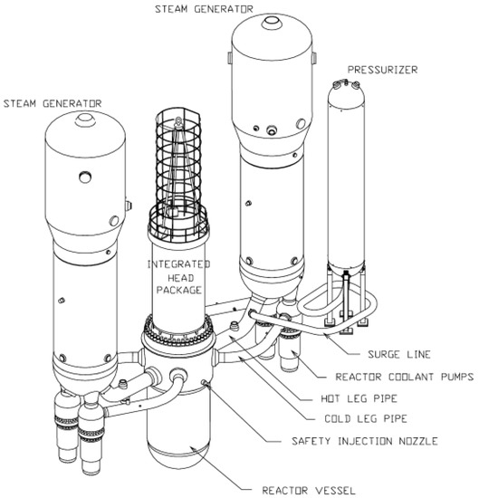
Figure 1.
Flowsheet of AP1000 reactor coolant system.
In the AP1000, the primary coolant water is pumped to the reactor core. The fission reaction generates the thermal energy to heat the coolant water. Then, it passes through the steam generator for transferring the heat into the secondary coolant water to generate steam. This is called the primary circuit. The steam from the steam generator drives the steam turbine to turn the generator. The steam is then condensed and returned to the steam generator as feedwater. This is called the secondary circuit.
The steam generator is a thermal-hydraulic component in PWR-type nuclear power plants. It is used to exchange heat between the primary and secondary circuits and provide steam to generate electricity, as shown in Figure 2. The heat exchange area of the steam generator consists of multiple equivalent inverted vertical U-tubes. Therefore, it is named UTSG.
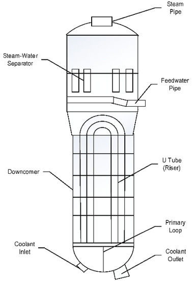
Figure 2.
Flowsheet of steam generator.
2.2. Control Problems of Steam Generator Water Level
For SG, the main goal of control system is to keep the water level within the allowable range by adjusting the feedwater flow rate when the steam demand changes due to changes in power demand.
The difficulties in designing an effective water level control system arise from several unfavorable factors summed up as follows:
- The open-loop dynamics of SG exhibit unstable behavior;
- The shrink and swell effects lead to strong inverse response behavior, which is remarkable at low power;
- Highly nonlinear characteristics, i.e., the dynamics of the process, vary with changes in operating power.
Figure 3 shows the step responses of the water level under different operating powers by using the model proposed by Irving [18]. It can be concluded from Figure 3 that the inverse response behavior and nonlinear dynamic characteristic of the water level are more obvious at low operating power, which greatly complicates the design of an effective water level control system.
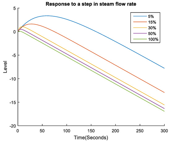
Figure 3.
Responses of the water level at different operating powers (%).
2.3. AP1000 Water Level Control System
As shown in Figure 4, the AP1000 water level control system uses an improved three-element control strategy to control the water level of steam generator [19]. Two error signals are used in this control strategy: one is the level error between the level set point and level measurement through a lead-lag filter, and the other is the flow error between feedwater and steam flow rates through a derivative filter. Then, these two error signals are sent to a proportional-integral (PI) controller to regulate the feedwater flow valve for maintaining the water level of SG at the desired value.
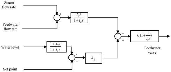
Figure 4.
Outline of AP1000 water level control system.
There are obvious differences between this three-element control and conventional single-loop PID control: (1) the error signal is not simply the subtraction of two signals, but is generated by derivative filter or derivative filter; (2) the combined feedback form of level error signals and flow error signal is adopted. Therefore, traditional single-loop PID tuning methods cannot be directly used. Moreover, strong inverse response behavior and highly nonlinear characteristics make controller tuning of water level control system more difficult.
3. Equivalent-Cascade IMC Tuning Method
In this part, IMC-PID tuning theory is first introduced in Section 3.1. Then, the water level control system is transformed into an equivalent cascade control system. The equivalent-cascade IMC-PID tuning method for the water level control system is proposed in Section 3.3. Finally, a summary of the algorithm is given in Section 3.4.
3.1. IMC-PID Tuning Theory
The IMC-PID tuning method was developed by Rivera and co-workers [20,21]. The advantage of this method lies in achieving a clear tradeoff between closed-loop performance and robustness against model mismatch by a single tuning parameter.
Figure 5 exhibits the block diagrams of IMC control, where G is the process, denotes a model of the process, and represents the IMC controller. The closed-loop transfer function in the IMC structure is as follows:
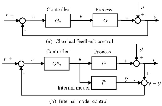
Figure 5.
Classical feedback control and internal model control.
For the nominal case (i.e., ), it can reduce to . In addition, we can convert the IMC structure into the classical feedback control structure as follows:
The IMC-based PID controller tuning consists of the following steps:
- Step 1.
- The process model can be expressed as , where contains any time delays and the right-half plane zeros with a steady-state gain of 1, and is the rest of .
- Step 2.
- The IMC controller is specified as , where f represents a low pass filter with a gain of 1. The filter f typically has the form , where r is sufficiently large to guarantee that the IMC controller is a proper transfer function. The parameter is the desired closed-loop time constant, which determines the speed of the response. The closed-loop transfer function for set-point changes is .
- Step 3.
- The equivalent feedback controller can be derived from Equation (1) and rearranged into the PID controller form.
Table 1 presents the PID controller tuning relations for two types of process models used in this study, which were derived by Chien and Fruehauf [22].

Table 1.
Internal model-control (IMC)-based proportional-integral-derivative (PID) controller settings.
3.2. Structure Analysis of Water Level Control System
Using block diagram representation, the water level control system of steam generator can be illustrated by Figure 6, where r is the water level set point, y1 is the water level of SG, y2 is the feed-water flow rate, u is feed-water valve, and d is the steam flow rate. Here, P1(s) indicates the transfer function of the valve to the feedwater flow rate, P2(s) represents the transfer function of the feedwater flow rate to the water level, and P3(s) indicates the transfer function of the steam flow to the water level.
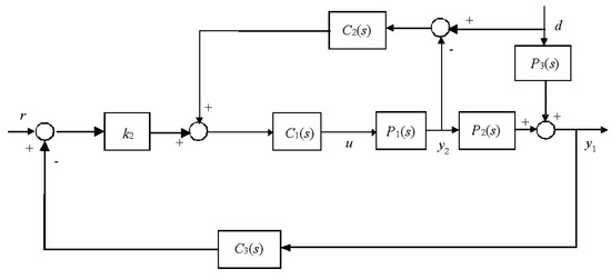
Figure 6.
Block diagram of water level control system.
Here, is the PI controller, is the derivative filter, and is the lead-lag filter.
To explain the function of each block further in the water level control system shown in Figure 6, the system can be transferred into the following equivalent block diagram, which is a cascade-feedforward control system.
In this equivalent cascade control system, the secondary loop is the feedwater flow control system, and the secondary controller is expressed as
When t2 > t1, we have
Thus, secondary controller can be approximated to the PI controller.
In the primary loop, and constitute the series form of the PID controller with a derivation filter [23].
where the denominator term serves as a derivative filter to reduce the sensitivity of noisy measurement. In order to eliminate the derivative kick for set-point changes, the derivative element is moved to the feedback path. The derivative filter parameter has a value between 0.05 and 0.2, with 0.1 being a common choice.
As shown in Figure 7, a static feedforward controller with a gain of 1 is designed to enhance the disturbance rejection performance of steam flow.
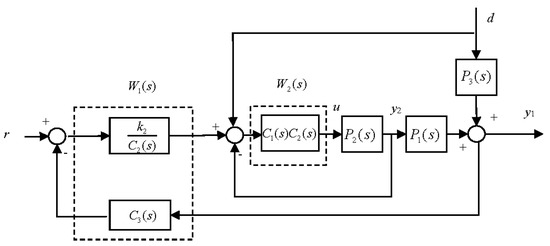
Figure 7.
Equivalent block diagram of water level control system.
In summary, if the equivalent cascade control loop is effectively tuned with Equation (2), then
controller parameters in the AP1000 water level control system can be obtained by
As the secondary loop works considerably faster than the primary loop, the condition t2 > t1 can be easily satisfied.
3.3. Equivalent-Cascade IMC-PID Tuning Method
For the cascade control system, the sequential tuning method is usually used to optimize controller’s parameters. However, after the secondary controller is tuned in this method, the dynamic model of the primary loop (including the secondary loop) must be re-identified, which is often time-consuming in practice. In this section, analytical tuning rules for the equivalent-cascade control system are derived based on IMC-PID method. This proposed method can simultaneously tune the primary and secondary loops and avoid the re-identification step in the tuning procedure.
Considering the inverse response characteristic of SG, the process transfer functions , , and are modeled as follows:
Applying IMC-PID tuning theory, the simultaneous tuning procedure for the equivalent-cascade control system is given as follows:
- Step 1.
- Designing an equivalent secondary controller
On the basis of the structure analysis in Section 3.2, the equivalent secondary controller can be approximated by a PI controller. As is modeled as a first-order system, the equivalent secondary controller can be designed as follows:
Here, is the desired closed-loop time constant of the secondary loop.
- Step 2.
- Designing of an equivalent primary controller
On the basis of IMC tuning theory, the closed-loop transfer function of the secondary loop can be approximated by a first-order system, i.e.,
By applying Skogestad’s half rule [24] and , the dynamic model of the primary loop can be approximated as follows:
The equivalent primary controller can be obtained as follows:
Here, is the desired closed-loop time constant of the primary loop.
- Step 3.
- By using Equation (5), controller parameters of the AP1000 water level control system are obtained as follows:
Therefore, we can derive the equivalent-cascade IMC-PID (EC-IMC) tuning rules for water level control system as follows:
In the above tuning procedure, the choice of the desired closed-loop time constant plays a key role. A larger value leads to a slower, conservative response with a long settling time, while a smaller value results in a more rapid and aggressive response with a shorter settling time [25,26]. In our work, an optimum value of the desired closed-loop time constant is obtained via searching optimization method based on the following enhanced integral square error (EISE) performance index:
This performance index consists of two terms. The first term, a penalty on the integral square error, represents regulation performance of process output for set-point tracking or disturbance rejection. The second term, a penalty on the rate of change of process input, is used to measure the required control effort and prevent aggressive control action. The relative priority of the two terms is set by the weight factor . If control action is aggressive in the simulation, weight factor should be increased.
Since minimizing the EISE criteria is a typical one-dimensional searching problem, an optimum value of the desired closed-loop time constant is obtained via the golden-section searching method, which is an improvement of the equal interval search method and can be guaranteed to converge [27], as shown in Figure 8. For the equivalent secondary control loop, we obtain optimum by evaluating the set-point tracking performance of feedwater flow, with in EISE. For the equivalent primary control loop, we obtain optimum by evaluating the disturbance rejection performance of steam flow, with in EISE.
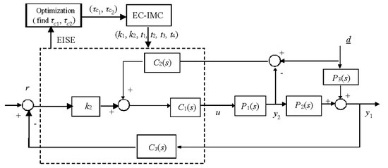
Figure 8.
Block diagram of the selection of closed-loop time constant.
3.4. Summary
With the change of the power level, the process dynamics of SG exhibits significant variation. Therefore, it is desirable to design a nonlinear controller to achieve satisfactory control performance at all power levels. As a practical and powerful method for control of nonlinear systems, gain scheduling is used to compensate for process variations of SG in our work. Usually, a gain-scheduled controller is obtained by interpolating between a set of linear controllers derived for a corresponding set of plant linearizations at several operating conditions [28].
Therefore, gain-scheduled equivalent-cascade IMC tuning method for water level control system is summarized as follows:
- Step 1.
- The operating power level is discretized by 10% from 20% to 100% and the linearized model of nuclear SG at each power level is identified;
- Step 2.
- Using the equivalent-cascade IMC-PID tuning method, local controller parameters at each power level are obtained based on the linearized model;
- Step 3.
- Piecewise linear function is utilized to construct a gain-scheduling module of controller parameters, in which the scheduling variable is the operating power level.
4. Experiment Result
In this section, we demonstrate the performance of the proposed method in AP1000 simulation platform CENTS, which is developed on the basis of rigorous first-principle models for one- and two-phase fluids. CENTS can simulate the transient behavior of AP1000 for all normal, abnormal, and accident conditions. Figure 9 shows graphical user interface of CENTS, which displays all plant parameters in real time and allows user’s interaction with the simulator.
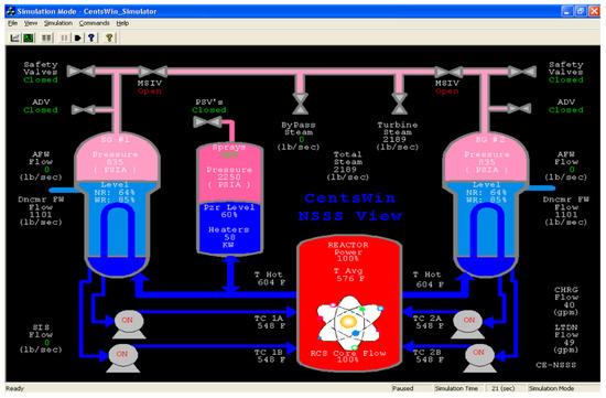
Figure 9.
Graphical user interface of CENTS.
To obtain a linearized model at each power level, a closed-loop identification test with a generalized binary noise (GBN) signal [29] is performed, instead of an open-loop test, as shown in Figure 10. In comparison with the open-loop test, the closed-loop test has numerous advantages, such as reducing the disturbance to process operation and being easy to carry out. In this study, we superpose the GBN test signal at the set point of water level and steam turbine power.
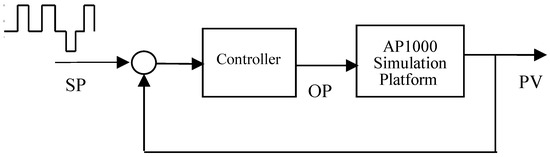
Figure 10.
Diagram of closed-loop test for AP1000 SG.
Figure 11 shows the identification test data for SG at a power level of 90%. The subfigures in first row present the GBN test signals at the set point of water level and steam turbine power, and the lower four subfigures indicate the system responses in steam flow rate, feedwater flow rate, pressure, and water level, respectively. By using the asymptotic identification method proposed by Zhu [29], we can obtain the linearized model of SG at each power level. Figure 12 illustrates the step responses of identification models at typical power levels, in which the step size of feedwater and steam flow rates are 1 lbm/s. We can see that at low-to-middle power levels, the steam-generator water level shows strong inverse response behavior.
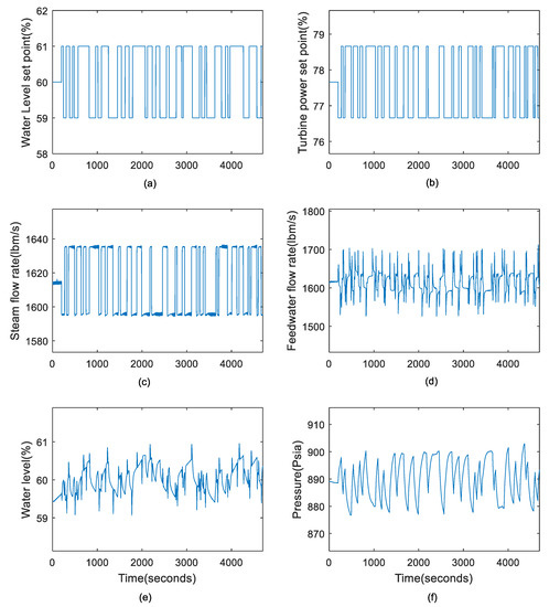
Figure 11.
Plots of identification data for steam generator. (a–c) refer to the input responses, and (d–f) are the output responses.
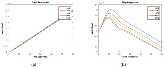
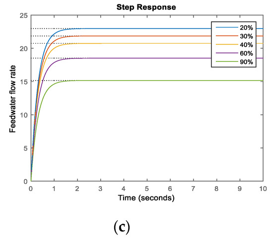
Figure 12.
Reponses of identification model to (a) 1 lbm/s step in feedwater flow rate, (b) 1 lbm/s step in steam flow rate, and (c) 1% step in feedwater valve.
By applying the equivalent-cascade IMC tuning method, we can obtain the tuning parameters of the AP1000 water level control system shown in Table 2. Figure 13 displays the desired closed-loop time constants of the primary/secondary loops at different power levels, which increase monotonously with the increase of power level. Figure 14 displays controller parameters at different power levels.
Table 2.
Tuning parameters of water level control system.
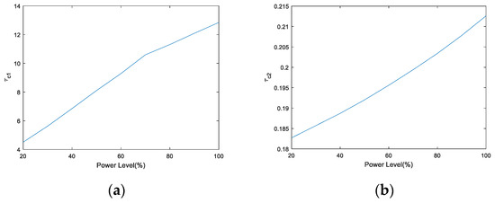
Figure 13.
and at different power levels. (a) refers to parameter , and (b) refers to parameter .
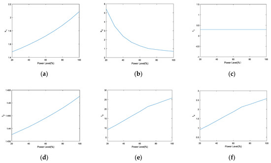
Figure 14.
Controller parameters at different power levels. (a–f) refer to parameters , , , , , and , respectively.
When implementing this strategy in DCS, only an additional gain scheduling module needs to be added to the existing three-element-control system, which adaptively adjusts the controller parameters based on the power level. Moreover, this proposed method almost does not increase additional computational load since the calculation of piecewise linear function is very fast.
To illustrate the performance of the proposed equivalent-cascade IMC tuning method, it is compared with the trial-and-error tuning method. Figure 15 shows the disturbance rejection performance for a power level step from 30% to 40% FP. The solid orange line is the proposed method, the blue solid line indicates the trial-and-error method, and the black dashed line represents the water level set point. We can see that the overshoot of the closed-loop response is slightly small and the settling time has a remarkable improvement. Figure 16 plots the valve opening of two methods. Figure 17 and Figure 18 show the water level behaviors of two other typical power level steps: from 75% to 65% and from 100% to 90%. The closed-loop performance of the water level based on the proposed method is considerably better than that based on the trial-and-error method for all power levels.
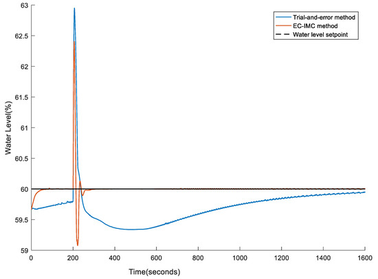
Figure 15.
Water level response of power level step change from 30% to 40%.
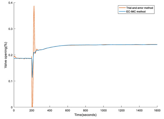
Figure 16.
Valve opening response of power level step change from 30% to 40%.
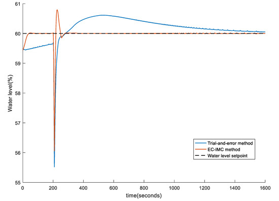
Figure 17.
Water level response of power level step change from 75% to 65%.
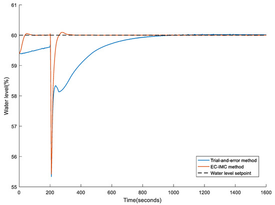
Figure 18.
Water level response of power level step change from 100% to 90%.
5. Conclusions
The steam generator serves as an important part of the nuclear power plant. The dynamics of the SG have the features of high nonlinearity and non-minimum phase, which bring great challenges to the design of the control system.
This paper presents a gain-scheduled equivalent-cascade IMC tuning method for the water level control system of a nuclear steam generator. At first, a water level control system for SG is transferred into an equivalent cascade-feedforward control system. Then, analytical tuning rules for the equivalent cascade control system are derived based on the IMC-PID method. Finally, gain scheduling is performed to reduce the effect of process nonlinearity. This approach can provide satisfactory performance at different power levels. Besides, it is simple to implement in practical applications. Experiment results demonstrate the effectiveness of the proposed method.
Author Contributions
Conceptualization, Z.X. and J.Z.; methodology, Z.X. and Q.F.; software, Q.F.; formal analysis, Z.X. and Q.F.; writing-original draft preparation, Q.F.; writing-review and editing, Z.X. and J.Z.; supervision, J.Z. All authors have read and agreed to the published version of the manuscript.
Funding
This research was funded by National Key Research and Development Program of China (No. 2017YFB0603703), NSFC-Zhejiang Joint Fund for the Integration of Industrialization and Informatization (No. U1809207).
Conflicts of Interest
The authors declare no conflict of interest.
References
- Wang, J.S.; Song, H.B.; Yan, S.J.; Sun, J.; Zhao, F.Y. Development of a simulation platform for dynamic simulation and control studies of AP1000 nuclear steam supply system. Ann. Nucl. Energy 2015, 85, 704–716. [Google Scholar]
- Kothare, M.V.; Mettler, B.; Morari, M.; Bendotti, P. Level control in the steam generator of a nuclear power plant. IEEE Trans. Control Syst. Technol. 2000, 8, 55–69. [Google Scholar] [CrossRef]
- Fang, F.; Xiong, Y. Event-driven-based water level control for nuclear steam generators. IEEE Trans. Ind. Electron. 2014, 61, 5480–5489. [Google Scholar] [CrossRef]
- Akkawi, M.; Jiang, J. An inverse control-based set-point function for steam generator level in nuclear power plants. IEEE Trans. Nucl. Sci. 2011, 58, 3291–3304. [Google Scholar] [CrossRef]
- Parlos, A.G.; Rais, O.T. Nonlinear control of U-tube steam generators via H∞ control. Control Eng. Pract. 2000, 8, 921–936. [Google Scholar] [CrossRef]
- Na, M.G.; Sim, Y.R. Design of an adaptive predictive controller for Steam Generators. IEEE Trans. Nucl. Sci. 2003, 50, 186–193. [Google Scholar]
- Amin, F.; Mehrdad, B. Adaptive critic-based neurofuzzy controller for the steam generator water level. IEEE Trans. Nucl. Sci. 2008, 55, 1678–1685. [Google Scholar]
- Ansarifar, G.R.; Davilu, H.; Talebi, H.A. Gain scheduled dynamic sliding mode control for nuclear steam generators. Prog. Nucl. Energy 2011, 53, 651–663. [Google Scholar] [CrossRef]
- Safarzadeh, O.; Khaki-Sedigh, A.; Shirani, A.S. Identification and robust water level control of horizontal steam generators using quantitative feedback theory. Energy Convers. Manag. 2011, 52, 3103–3111. [Google Scholar] [CrossRef]
- Wei, L.; Fang, F.; Shi, Y. Adaptive backstepping-based composite nonlinear feedback water level control for the nuclear U-tube steam generator. IEEE Trans. Control Syst. Technol. 2014, 22, 369–377. [Google Scholar] [CrossRef]
- Carli, R.; Dotoli, M.A. A distributed control algorithm for waterfilling of networked control systems via consensus. IEEE Contr. Syst. Mag. 2017, 1, 334–339. [Google Scholar] [CrossRef]
- He, P.; Li, M.S.; Zhao, L.; Venkatesh, B.; Li, H.W. Water-filling exact solutions for load balancing of smart power grid systems. IEEE Trans. Smart Grid 2018, 9, 1397–1407. [Google Scholar] [CrossRef]
- Liu, X.; Jiang, D.; Lee, K.Y. Quasi-min-max fuzzy MPC of UTSG water level based on off-line invariant set. IEEE Trans. Nucl. Sci. 2015, 62, 2266–2272. [Google Scholar] [CrossRef]
- Ansarifar, G.R. Control of the nuclear steam generators using adaptive dynamic sliding mode method based on the nonlinear model. Ann. Nucl. Energy 2016, 88, 280–300. [Google Scholar] [CrossRef]
- Astrom, K.J.; Hagglund, T. PID Controllers: Theory, Design and Tuning; Instrument Society of America: Research Triangle Park, NC, USA, 1995. [Google Scholar]
- Schulz, T.L. Westinghouse AP1000 advanced passive plant. Nucl. Eng. Des. 2006, 236, 1547–1557. [Google Scholar] [CrossRef]
- Matzie, R.A. AP1000 will meet the challenges of near-term deployment. Nucl. Eng. Des. 2008, 238, 1856–1862. [Google Scholar] [CrossRef]
- Irving, E.; Miossec, C.; Tassart, J. Towards efficient full automatic operation of the PWR steam generator with water level adaptive control. In Boiler Dynamics and Control in Nuclear Power Stations; Thomas Telford Publishing: London, UK, 1980. [Google Scholar]
- Sun, H.H. Generation III Nuclear Power Technology AP1000; China Electric Power Press: Beijing, China, 2010. [Google Scholar]
- Rivera, D.E.; Morari, M.; Skogestad, S. Internal model control. 4. PID controller design. Ind. Eng. Chem. Res. 1986, 25, 252–265. [Google Scholar] [CrossRef]
- Morari, M.; Zafiriou, E. Robust Process Control; Prentice-Hall: Englewood Cliffs, NJ, USA, 1989. [Google Scholar]
- Chien, I.-L.; Fruehauf, P.S. Consider IMC tuning to improve controller performance. Chem. Eng. Prog. 1990, 86, 33–41. [Google Scholar]
- Seborg, D.E.; Edgar, T.F.; Mellichamp, D.A.; Doyle, F.J.D., III. Process Dynamics and Control; John Wiley & Sons, Inc.: Hoboken, NJ, USA, 2011. [Google Scholar]
- Skogestad, S. Simple analytic rules for model reduction and PID controller tuning. J. Process Control 2003, 13, 291–309. [Google Scholar] [CrossRef]
- Chen, D.; Seborg, D. PI/PID controller design on direct synthesis and disturbance rejection. Ind. Eng. Chem. Res. 2002, 41, 4807–4822. [Google Scholar] [CrossRef]
- Pai, N.S.; Chang, S.C.; Huang, C.T. Tuning PI/PID controllers for integrating processes with deadtime and inverse response by simple calculations. J. Process Control 2010, 20, 726–733. [Google Scholar] [CrossRef]
- Nocedal, J.; Wright, S.J. Numerical Optimization; Springer: New York, NY, USA, 2006. [Google Scholar]
- Rugh, W.J.; Shamma, J.S. Research on gain scheduling. Automatica 2000, 36, 1401–1425. [Google Scholar] [CrossRef]
- Zhu, Y.C. Multivariable System Identification for Process Control; Elsevier: London, UK, 2001. [Google Scholar]


© 2020 by the authors. Licensee MDPI, Basel, Switzerland. This article is an open access article distributed under the terms and conditions of the Creative Commons Attribution (CC BY) license (http://creativecommons.org/licenses/by/4.0/).