Article

Iterative Method for Tuning Multiloop PID Controllers Based on Single Loop Robustness Specifications in the Frequency Domain

1
Department of Electrical Engineering and Automation, University of Cordoba, Campus de Rabanales, 14071 Cordoba, Spain
2
Department of Mechanical Engineering, University of Cordoba, Campus de Rabanales, 14071 Cordoba, Spain
3
Department of Computer Science and Automatic Control, National Distance Education University, Juan del Rosal 16, 28040 Madrid, Spain
*
Author to whom correspondence should be addressed.
Processes 2021, 9(1), 140; https://doi.org/10.3390/pr9010140
Submission received: 13 December 2020 / Revised: 7 January 2021 / Accepted: 11 January 2021 / Published: 12 January 2021
(This article belongs to the Section Process Control and Monitoring)

Abstract

:
Multiloop proportional-integral-derivative (PID) controllers are widely used for controlling multivariable processes due to their understandability, simplicity and other practical advantages. The main difficulty of the methodologies using this approach is the fact that the controllers of different loops interact each other. Thus, the knowledge of the controllers in the other loops is necessary for the evaluation of one loop. This work proposes an iterative design methodology of multiloop PID controllers for stable multivariable systems. The controllers in each step are tuned using single-input single-output (SISO) methods for the corresponding effective open loop process (EOP), which considers the interaction of the other loops closed with the controllers of the previous step. The methodology uses a frequency response matrix representation of the system to avoid process approximations in the case of elements with time delays or complicated EOPs. Consequently, different robustness margins on the frequency domain are proposed as specifications: phase margin, gain margin, phase and gain margin combination, sensitivity margin and linear margin. For each case, a PID tuning method is described and detailed for the iterative methodology. The proposals are exemplified with two simulations systems where the obtained performance is similar or better than that achieved by other authors.

1. Introduction

Traditional proportional-integral-derivative (PID) controllers have been the preferred control algorithm in most industrial applications for decades because of their acceptable control effect, satisfactory robustness and simple structure [1]. There are thousands of works about PID controller design methods and PID tuning rules, most of them developed for single input single output (SISO) loops. However, most industrial processes are multivariable systems consisting of multiple inputs and multiple outputs with couplings between them. These process interactions can seriously deteriorate the control system performance when they are not considered in the design stage.
There are mainly two control approaches for dealing with interactions in multivariable systems: decentralized (or multiloop) control, or centralized control. The multiloop approach first decides the different loops pairing the inputs and outputs according to some measurement such as the relative gain array (RGA) [2] with its many variants; then, a single controller is tuned for each loop (Figure 1). In contrast, using a centralized control, a full matrix controller is designed. Although this last approach can achieve a greater interaction reduction and a better performance than multiloop control, it should be implemented when it is justified since it shows some disadvantages over the first approach: more complicated design, higher sensitivity to modeling errors and uncertainties, more difficulty of implementation and so on [3]. Consequently, the multiloop control is preferred when the interaction level and characteristics of the multivariable process allow one to obtain a good performance using it. An intermediate approach consists of designing a decoupling compensator to reduce the interactions of the original system and obtain a diagonal dominant apparent process and then calculating a multiloop control for this [4].
Multiloop PID controllers are widely utilized due to their simple control structure, robustness performance, easiness to handle loop failure, easy understandability, fewer tuning parameters and other practical advantages. There are different types procedures to carry out the design. Detuning methods design the PID controllers for each loop using SISO techniques and ignoring the interactions from other loops and then, detune the parameters until achieving some limit such as the biggest-log-modulus (BLT) [5], which determines the tradeoff between performance and stability. They are very simple; however, they do not exploit the multivariable information of the process model to obtain a better system response.
Sequential loop closing methods close the loops one after the other, usually starting with the fastest one. They take into account the process interaction of the loop in the closing of the next loop, and so on [6,7]. The final design depends on the order of loop closing and iteration procedures are necessary. In the iterative design methods, the full process model information is considered to tune the controllers and meet some SISO specification in each loop. Starting from an initial guess of controller parameters set, each controller is retuned independently with the other loops being closed using the controllers calculated in the previous step. The iterative procedure is carried out until the controller parameters converge or the loop specifications are achieved.
Among alternative methods, other methodologies perform the design without iterations by means of simultaneous equation solving [8,9] or nonlinear optimization procedures with matrix inequality constraints [10,11], evolutionary or bioinspired algorithms [12,13]. Other authors use independent design procedures such as the application of internal model control to the multiloop PID design [14,15], the combination of independent design and Nyquist stability analysis [16], the dominant pole placement in [17], the direct method in [18,19] based on effective open loop processes, the decomposition of the process into a sum of basic modes of the multiscale control scheme [20], the single-iteration strategy in [21] with gain and phase margin specifications and so on. The main advantage of these methods is that they do not need a prior knowledge of the controllers in the other loops and therefore the SISO controller is tuned independently by using some bounds to guarantee stability and performance. Nevertheless, they can show some disadvantages that can limit their application. Poor resulting performance can be derived due to not using the information of the controllers in the other loops to calculate the real equivalent SISO processes. In addition, several of these methods may require model reductions to be applied, even more in the case of systems with multiple time delays where the equivalent transfer functions of the process are irrational. Furthermore, they can achieve satisfactory performance for 2 × 2 processes; however, their extensions to higher dimensional systems are usually difficult because of complicated calculations or important model approximations.
The common difficulty that all these multiloop methodologies attempt to overcome is the fact the controllers interact with each other. Therefore, the evaluation of the real performance of one loop requires knowing the controller dynamics in other loops. This work proposes an iterative methodology for tuning multiloop PID controllers for stable multivariable processes assuming a previous proper input–output pairing. The method is based on a structural decomposition of the system into separate SISO loops. The controller of each individual loop is tuned according to the corresponding effective open loop process (EOP) that includes the interaction transmission of the other loops being closed and consequently, needs the set of controllers calculated in the previous iteration step. Therefore, the method considers the full information of the multivariable process model, which is based on a frequency response matrix representation to avoid approximations or reductions of the EOP in case of systems with multiple time delays. Due to this representation, various SISO robustness specifications on the frequency domain are proposed for tuning each independent loop using different SISO methodologies. An initial version of this methodology was introduced only for 2 × 2 processes in [22], where phase margin, gain margin or a combination of them were used as specifications for the PID tuning methodology in [23], and where the proposed designs obtained less conservative responses than those achieved by other frequency response methods based on Gershgorin’s bands [24]. In this work, further research has been performed extending the method for n × n systems and considering new robustness specifications and SISO PID tuning methods.
The paper is structured as follows. Section 2 provides a preliminary background for the proposed methodology such as the effective open loop processes, the different robustness specifications covered in this work and their corresponding SISO PID tuning methods. In Section 3, the proposed methodology is described. Section 4 illustrates the proposal with several simulation examples and different robustness margins. Finally, conclusions are summarized in Section 5.

2. Preliminary Background

2.1. Effective Open Loop Processes

From Figure 1, the process is given by the n × n transfer matrix G(s) in (1), where gij(s) represents the transfer function between output yi and input uj, and the decentralized controller is given by the diagonal matrix K(s) in (2), where ki(s) is the controller for the loop between output yi and input ui. The diagonal structure of K(s) is obtained assuming a diagonal input–output pairing for introducing the notation of the proposed methodology. However, the interaction analysis can recommend other input–output pairings. To maintain a diagonal K(s) structure in these cases, the G(s) process matrix must simply be reordered accordingly.
G ( s ) = ( g 11 ( s ) g 1 j ( s ) g 1 n ( s ) g i 1 ( s ) g i j ( s ) g i n ( s ) g n 1 ( s ) g n j ( s ) g n n ( s ) )
K ( s ) = ( k 1 ( s ) 0 0 0 k i ( s ) 0 0 0 k n ( s ) )
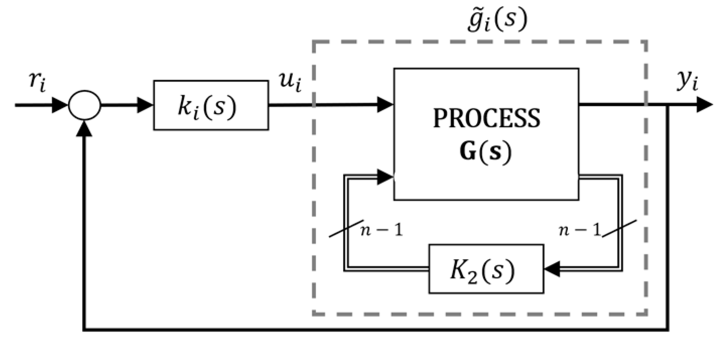
Supposing that loop i is still open while the other n − 1 loops are closed using controllers tuned by some method, it is desired to tune the controller ki(s). To analyze the apparent open loop process between output yi and input ui under these conditions, the structural decomposition scheme in Figure 2 is proposed. In this scheme, K1(s) represents the controller ki(s) and K2(s) is the set of other n − 1 controllers in their corresponding closed loop. From this scheme, the real open loop transfer function between output yi and input ui, and named g ˜ i ( s ) , can be obtained as follows in (3), where G12(s) is a row vector with the n − 1 elements of row i different from gii(s), G21(s) is a column vector with n − 1 elements of column i different from gii(s), G22(s) is a n − 1 × n − 1 matrix with the other elements of G(s), and I is the n − 1 order identity matrix. Equation (3) can also be expressed in terms of the G(s) elements, as shown in (4).
g ˜ i ( s ) = g i i ( s ) G 12 ( s ) K 2 ( s ) ( I + G 22 ( s ) K 2 ( s ) ) 1 G 21 ( s )
g ˜ i ( s ) = g i i ( s ) j = 1 j i n g i j ( s ) k j ( s ) g j i ( s ) 1 + g j j ( s ) k j ( s )
These g ˜ i ( s ) transfer functions are the effective open loop processes (EOPs) and they capture the effective dynamics of each open loop process while the other loops are closed with their corresponding controllers. They are a key concept of the proposed methodology because they allow one to decompose the control system into equivalent SISO control loops to be designed. Then, the stability of a decentralized control system can be achieved if the characteristic equation of each equivalent single loop, as shown in (5), does not contain zeros in the right half plane [25].
1 + k i ( s ) g ˜ i ( s ) = 0 i
Unlike the diagonal processes gii(s), the EOPs consider the interaction effects with the other loops. However, the g ˜ i ( s ) transfer functions are not an intrinsic property of the G(s) since they depend on the controllers tuned in the other loops. The controller design can be performed using SISO loops methods; nevertheless, the modification of any controller will affect the other loops, where it will be necessary to update the controller tuning. Hence the proposed methodology, and others, applies iterations for tuning the controllers until their parameters converge or the design specifications are achieved. The EOP expressions for 2 × 2 processes are given in (6) where their dependency on the alternate loop controller can be appreciated.
g ˜ 1 ( s ) = g 11 ( s ) g 12 ( s ) k 2 ( s ) g 21 ( s ) 1 + g 22 ( s ) k 2 ( s ) g ˜ 2 ( s ) = g 22 ( s ) g 21 ( s ) k 1 ( s ) g 12 ( s ) 1 + g 11 ( s ) k 1 ( s )

2.2. SISO PID Tuning Methods and Robutstness Specifications

There are many SISO methods to calculate a PID controller ki(s) for the corresponding EOP g ˜ i ( s ) . However, according to (4), the EOPs of a multivariable process can be complicated transfer functions and given the diverse casuistry of models, it is impossible to use a particular PID tuning formula such as those for first order plus time delay systems, second order plus time delay systems and so on. Furthermore, in case of systems with multiple time delays, the resulting EOPs are usually irrational transfer functions. In these cases, some methods suggest obtaining simplified EOP transfer functions by approximation. In contrast, the proposed methodology works using an array of the frequency response of the EOPs, and hence no reduction is performed, and any arbitrary order system can be represented.
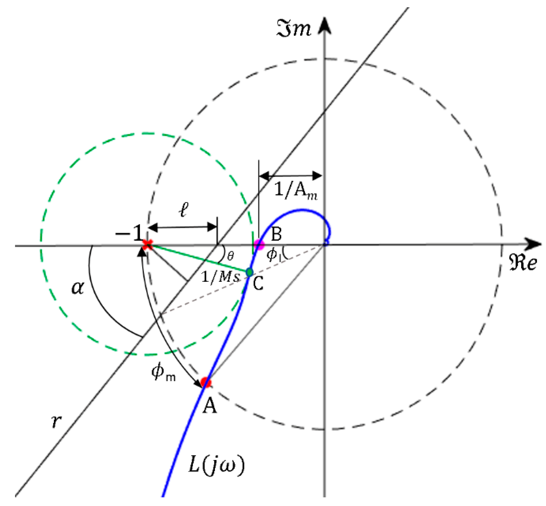
For this reason, the proposed SISO PID tuning methods to be used in the iterative design procedure must be based on this kind of representation and frequency domain specifications. In this work, the proposed PID tuning methodologies use the Nyquist diagram as a design tool assuming that the EOPs and controllers do not contain poles in the right half plane and therefore, stability is achieved if there are no encirclements to the critical point (−1, 0). The following robustness margins are proposed as specifications: phase margin, gain margin, maximum sensitivity, and linear margin. They measure in different ways “how far from instability” the nominal loop is. They are described below and are represented in Figure 3.
Phase margin and gain margin are classical robustness specifications. The phase margin (ϕm) indicates the phase lag that can be added to the loop before reaching the stability limit at the frequency ωcp where the Nyquist plot of the open loop transfer function L(jω) intersects the unit circle (point A in Figure 3). The gain margin (Am) is the amount of gain required in the loop to reach instability, and it is computed at the frequency ωcg where the phase lag of the open loop transfer function is 180° (point B in Figure 3). A positive phase margin and a gain margin greater than one are necessary to ensure closed loop stability for stable open loop systems, and they are calculated according to the corresponding expressions in (7). Typical values of ϕm are in the range [30°, 60°] and usual values of Am are in the range [2, 5].
ϕ m = 180 ° + arg ( L ( j ω c p ) ) A m = 1 L ( j ω c g )
The maximum sensitivity Ms is the inverse of the shortest distance of the Nyquist plot to the critical point −1; therefore, it is related to the radius of the circle centered in −1 and tangent to the Nyquist curve (point C), which must be consequently outside this circle. This margin ensures lower bounds on ϕm and Am at the intersection points of this circle with the unit circle and the negative real axis, respectively. The value of Ms can be calcalculated according to (8) and typical values are in the range from 1.4 to 2 [26]. In [27], an alternative linear margin is proposed for robustness. It is defined by the line r that intersects the negative real axis at the point (−1 + , 0) with an angle α (as depicted in Figure 3). The Nyquist curve must be placed below this line for stability, guaranteeing the lower bounds on ϕm, Am and Ms given in (9). By means of this linear margin, the PID control design can be formulated as a linear programming problem.
M s = max ω | S ( j ω ) | = max ω | 1 1 + L ( j ω ) |
ϕ m ϕ l = arcos ( ( 1 ) sin 2 α + cos α 1 ( 1 ) 2 sin 2 α ) A m 1 / ( 1 ) M s 1 / ( sin α )
In the following subsections, two SISO PID tuning methods are briefly described as candidates to be used in the proposed decentralized methodology. The first one uses either ϕm, Am or Ms as specifications; the second one is intended for the linear margin.

2.2.1. PID Tuning by Moving a Point of the Nyquist Diagram

Given a process g(s) and a controller k(s), this method designs k(s) by moving a point of the Nyquist diagram of g(s), in the absence of the controller, to a desired target point on the Nyquist plot of the open loop transfer function L(s) = g(s)k(s). In other words, it forces the Nyquist diagram of L(s) to pass through a specific point of the complex plane at a design frequency. After defining this point and the frequency design ωd, the magnitude and argument of g(jωd) and L(jωd) are known. The magnitude and argument of k(s) and its complex expression at this frequency can be derived as follows:
L ( j ω d ) = g ( j ω d ) k ( j ω d ) k ( j ω d ) = L ( j ω d ) / g ( j ω d ) { | k ( j ω d ) | = | L ( j ω d ) | / | g ( j ω d ) | = | k ( ω d ) | arg ( k ( j ω d ) = arg ( L ( j ω d ) ) arg ( g ( j ω d ) ) = φ k ( ω d ) k ( j ω d ) = | k ( ω d ) | ( cos φ k ( ω d ) + j sin φ k ( ω d ) )
In [23], this procedure is used for the design of non-interactive PID controllers with phase margin and gain margin as specifications for stable processes. The transfer function of a non-interactive PID controller is given by (11), where KP is the proportional gain, TI is the integral time constant and TD, the derivative time constant.
k ( s ) = K P ( 1 + 1 T I s + T D s )
Decomposing its frequency response at frequency ωd into real and imaginary parts and comparing with the last equation in (10), the conditions in (12) are obtained. Once the target point of L(jω) is defined in the Nyquist diagram, |kd)| and φkd) are obtained according to (10). Thus, the PID parameters can be calculated from (12).
k ( j ω d ) = K P ( 1 j 1 T I ω d + T D j ω d ) = | k ( ω d ) | ( cos φ k ( ω d ) + j sin φ k ( ω d ) ) K P = | k ( ω d ) | cos φ k ( ω d ) ( K P T D ω d K P T I ω d ) = | k ( ω d ) | sin φ k ( ω d ) ( T D ω d 1 T I ω d ) = tan φ k ( ω d )
To ensure a specified phase margin ϕm at frequency ωd, the target point at the Nyquist plot of L(jω) will be the point A in Figure 3. Then, the magnitude and argument of the controller are as follows:
{ | L ( j ω d ) | = 1 arg ( L ( j ω d ) ) = 180 ° + ϕ m { | k ( ω d ) | = 1 / | g ( j ω d ) | φ k ( ω d ) = 180 ° + ϕ m arg ( g ( j ω d ) )
Similarly, to guarantee a given gain margin Am, the Nyquist diagram must pass through point B of Figure 3. The resultant conditions for the controller are given in (14).
{ | L ( j ω d ) | = 1 / A m arg ( L ( j ω d ) ) = 180 ° { | k ( ω d ) | = 1 A m | g ( j ω d ) | φ k ( ω d ) = 180 ° arg ( g ( j ω d ) )
In this methodology [23], the ratio β = TD/TI must also be specified. Substituting TD = βTI into the last equation of (12), a quadratic equation in TI is achieved. After solving this equation, the expressions to calculate the PID controller parameters are summarized as follows:
T I = tan φ k ( ω d ) + ( tan φ k ( ω d ) ) 2 + 4 β 2 β ω d T D = β T I K P = | k ( ω d ) | cos φ k ( ω d )
Considering that a PID controller can add a phase in the range [−90°, +90°], the range of possible design frequencies is limited for the phase difference between the desired target point on L(jω) and the process g(jω) according to the argument condition in (10). Any frequency ωk producing that −90° ≤ φkk) ≤ +90° is a candidate for the design frequency. Between these possible frequencies, the method in [23] proposes choosing the frequency that allows it to maximize the integral gain (KI = KP/TI). This integral gain is related to the closed loop performance in terms of load disturbance rejection, which can be expressed according to the integrated error. Maximizing KI leads to minimizing the integrated error. However, a solution is not guaranteed when using simultaneously phase and gain margins as a combined specification. In this case, to reach both margins with the same PID parameters, the process frequency response must fulfill a set of conditions described in [23] and the design frequency cannot usually be selected.
In [28], a similar procedure is proposed for the tuning PID controllers based on the sensitivity margin Ms as robustness specification. In this case, the desired target point at frequency ωd is defined by the point C in Figure 3, that is, the tangency point of the Nyquist plot with the circle of radius 1/Ms and centered at −1. Given the magnitude of this radius (1/Ms) and the depicted angle θ with the tangency point, the coordinates of point C are given by (16), where φC is the angle of L(jωd) at this point with respect to the negative real axis.
{ x C = 1 + cos θ / M s = | L ( j ω d ) | cos ( φ C ) y C = sin θ / M s = | L ( j ω d ) | sin ( φ C )
From (16), the magnitude and phase of L(jωd) can be calculated as shown in (17). Additionally, then, conditions in (18) for the magnitude and phase of the controller can be obtained.
φ C = arctan ( sin θ cos θ M s ) { arg ( L ( j ω d ) ) = 180 ° + φ C | L ( j ω d ) | = sin θ M s sin φ C
{ φ k ( ω d ) = 180 ° + φ C arg ( L ( j ω d ) ) | k ( ω d ) | = sin θ M s sin φ C | g ( j ω d ) |
Similarly to the previous case, the PID controller parameters can be calculated using the Equation (15) for a given ratio β. In this case, it is also necessary to verify the tangency of the Nyquist diagram of L(jω) at the contact point C with the circle centered at −1. The tangency condition function TCF in (18) must be below a given tolerance value to obtain a proper design.
Again, any frequency ωk can be chosen as the frequency design as long as the phase φkk) that must be added by the PID controller at this frequency is within the range [−90°, +90°]. The method in [28] calculates a PID controller in each frequency of the aforementioned range and evaluates the tangent condition in each design. Among all valid designs, the one with maximum integral gain KI is selected for improving load disturbance rejection.
T C F ( ω ) = ( a ( ω , θ ) K P + b ( ω , θ ) K P / T I + c ( ω , θ ) K P T D ) 2 { a ( ω , θ ) = ( arg ( g ( j ω ) ) ) ω cotan ( θ + arg ( g ( j ω ) ) | g ( j ω ) | ( | g ( j ω ) | ) ω b ( ω , θ ) = 1 ω 2 1 ω | g ( j ω ) | ( | g ( j ω ) | ) ω cotan ( θ + arg ( g ( j ω ) ) ω ( arg ( g ( j ω ) ) ) ω c ( ω , θ ) = 1 + ω | g ( j ω ) | ( | g ( j ω ) | ) ω + ω cotan ( θ + arg ( g ( j ω ) ) ( arg ( g ( j ω ) ) ) ω
The particular cases of proportional-integral (PI) control (β = 0) and proportional-derivative (PD) control can also be derived from (12). In these cases, the corresponding controller time constant is obtained according to (20). For the PI control the design range frequency is limited to frequencies where the PI phase contribution φkk) is into the range [−90°, 0°]. For PD control, the range is restricted to the range [0°, +90°]. In this last case, there is no integral gain and maximizing the proportional gain KP is used as a rule to select the design.
P I   c o n t r o l : T I = 1 ω d tan φ k ( ω d ) P D   c o n t r o l : T D = tan φ k ( ω d ) ω d

2.2.2. PID Tuning by Linear Programming

This PID tuning method was proposed in [27] for stable systems. The method shapes the Nyquist diagram of the open loop process L(jω) forcing it to be placed below the line r in Figure 3. This line is defined by the intersection point in the negative real axis at −1 + , and the line slope given by angle α. It is also based on an array representation of the system frequency response. The design problem can be formulated as a linear programming optimization using a PID controller with the parallel structure in (21), where KD is the derivative gain (KD = KPTD). This structure can be parameterized as in (22) where ρ is the controller parameter vector and ψ(s) is a vector depending only on s.
k ( s ) = K P + K I s + K D s
k ( s ) = [ 1 , 1 s , s ] [ K P K I K D ] = ψ T ( s ) ρ
Then, any point at frequency ωk of the Nyquist plot of L(jω) can be expressed as a linear function of the controller parameters as follows:
L ( j ω k ) = g ( j ω k ) k ( j ω k ) = g ( j ω k ) [ 1 , j 1 ω k , j ω k ] [ K P K I K D ] = g ( j ω k ) ψ T ( j ω k ) ρ L ( j ω k ) = e ( g ( j ω k ) ψ T ( j ω k ) ) ρ + j m ( g ( j ω k ) ψ T ( j ω k ) ) ρ
Every point of L(jω) must be below this line r. Thus, there is a constraint at each frequency ωk of the L(jω) frequency response array considering the line r in Equation (24). When it is desired to maximize the integral gain KI in order to optimize the closed loop performance for load disturbance rejection, the optimization problem in (25) can be defined for given values of ℓ and α.
y tan α · ( x + 1 ) 0
maximize [ 0 , 1 , 0 ] ρ subject   to [ cot α · m ( g ( j ω k ) ψ T ( j ω k ) ) e ( g ( j ω k ) ψ T ( j ω k ) ) ] ρ 1 ω k

3. Proposed Methodology

This section describes the proposed iterative algorithm for the multiloop PID design. It supposes a decentralized control structure using a diagonal input–output pairing of the system elements. Therefore, a previous resolution of the pairing problem and an appropriate rearrangement of process matrix G(s) must be performed. The proposed method is aimed for n × n square stable processes. Its flow diagram is depicted in Figure 4; it is basically composed by the initialization of EOPs and the iteration loop through a set of steps: SISO PID controller design for current EOPs, recalculation of EOPs, analysis of cost index for specifications, and checking of specification achievement. In these steps, the superscript m of variables denotes the iteration number, while the subscript i indicates the loop number from 1 to n.
First, the iteration variable m is set to zero and the initial EOP g ˜ i 0 ( s ) of each loop i must be obtained before entering the iteration loop. As there are no previous controllers in the first iteration, expressions (3) or (4) cannot be used for the first EOP calculation. In this work, it was proposed to use the reduced equivalent open loop process (REOP) in (25) as the initial EOP g ˜ i 0 ( s ) , where controller terms are excluded [29]. Since PID controllers have integral action, assuming a closed loop perfect control, the REOPs can be approximated from the structural decomposition in (3) as follows:
g ˜ i 0 ( s ) = g i i ( s ) G 12 ( s ) G 22 1 ( s ) G 21 ( s )
Then, a PID controller k i m ( s ) must be tuned for each EOP according to the required specifications by means of some SISO method. Next, the EOP of each loop is updated using these new controllers and expression (4). As the EOPs can be irrational transfer functions, the proposed methodology works using a frequency response array for EOP representation instead of a concrete transfer function. Consequently, the SISO PID tuning methodologies must allow one to perform the design from a frequential description of the process.
Using the new recalculated EOPs g ˜ i m + 1 ( j ω ) and the current k i m ( j ω ) controllers, the achievement of desired specifications in all the loops must be evaluated and quantified into a cost index Jm. If this index is below a user-defined tolerance, the specifications have been achieved and the current design is accepted; otherwise the procedure is iterated, the iteration variable is incremented and new PID controllers are tuned using the updated EOPs. The iteration process continues until a design is accepted, the cost index does not change in three consecutive iterations, or a maximum number of iterations is reached. In the last two cases, the design with the smallest J index is selected. The main drawback of the proposed procedure consists of not guaranteeing the convergence. However, it works properly in most tested examples.
The PID tuning method and the cost index definition depend on the required specification. In the next subsections, these issues are described in detail for each proposed robustness margin. It is also necessary to note that other SISO methods can be used as long as they can be performed using a process representation based on a frequency response array.

3.1. Phase Margin Case

In this case, for each loop i of a n × n process, a desired phase margin ϕmi* and a controller time constant ratio βi must be provided as procedure inputs together with the process transfer matrix G(s). In any iteration, there are n EOPs g ˜ i m ( j ω ) calculated from the previous iteration m − 1. The PID tuning procedure of each loop is based on the method in [23], which has been adapted to work with a frequency response array representation. It may be divided in the following steps:
  • Given the frequency response array of the EOP g ˜ i m ( j ω ) , obtain the design frequency range for which the tuning of PID controller parameters is possible according to the argument condition in (10). The phase provided by the controller must be in the range from −90 to 90°.
  • Determine the magnitude and phase contributions of the controller according to (13) for each possible design frequency ωk.
  • Calculate the PID parameters according to (15) for each frequency ωk. As a result, as many PID control candidates as design frequencies are obtained.
  • Evaluate stability of each design and choose that one with the greatest integral gain.
After obtaining PID controllers for each g ˜ i m ( j ω ) , the EOPs are recalculated with them and the achieved phase margin ϕmi is evaluated for each new pair k i m ( j ω ) g ˜ i m + 1 ( j ω ) . Then, the cost index defined in (27) is obtained. If its value is less than a given tolerance, the multiloop PID design is accepted. A tolerance of 0.015 by loop is used for this index in this work.
J = i = 1 n | ϕ m i * ϕ m i | ϕ m i *

3.2. Gain Margin Case

This case is very similar to the previous one. A desired gain margin Ami* is specified for each loop instead of a phase margin. The magnitude and phase contributions of the controller are calculated by means of expressions (14). The cost index to validate the multiloop PID design is given by (28), where Ami is the obtained gain margin for k i m ( j ω ) g ˜ i m + 1 ( j ω ) .
J = i = 1 n | A m i * A m i | A m i *

3.3. Combined Phase and Gain Margin Case

When only phase margin (or gain margin) is specified as a single requirement, the achieved design cannot ensure the loop stability. This problem can be solved using as specification a combination of desired gain margin Ami* and phase margin ϕmi* for each loop. If the phase margin is positive and the gain margin is greater than one, the loop will be stable. The procedure is very similar to previous cases with the same steps. Now the cost index for the decentralized PID control design is given by (29). It is composed of two terms for each loop: one for the phase margin and another for the gain margin. A double tolerance of the previous cases is used for this index by loop.
J = i = 1 n ( | ϕ m i * ϕ m i | ϕ m i * + | A m i * A m i | A m i * )
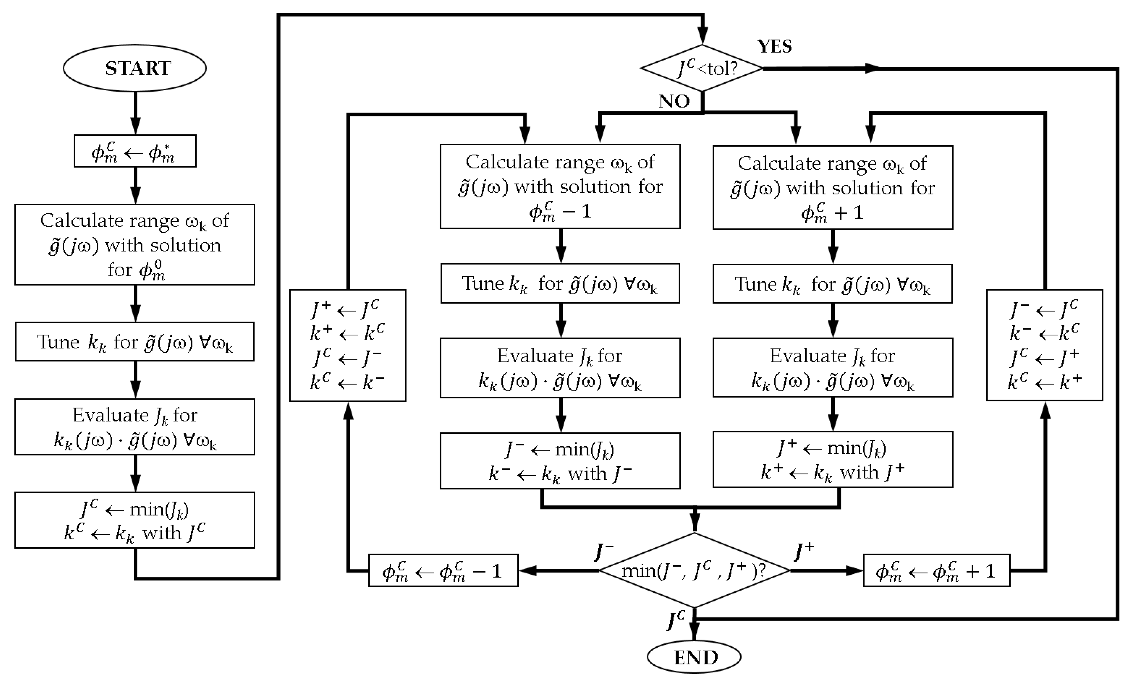
The main difference of this case is found in the SISO PID tuning algorithm to obtain simultaneously both margins in the loop. This achievement is not always possible, even more when these requirements are aimed in all the loops. Therefore, the proposed method relaxes the phase margin specification in one direction by means of a path-following algorithm. It is an adaptation of the analytical method in [23] using a frequency response array representation. The algorithm receives as inputs the desired gain margin A m i * and phase margin ϕ m i * for the loop i, the frequency response array of the EOP and the time constant ratio β for the PID controller of this loop. It provides as output the PID control k i C that minimizes the cost index (28) in loop i using the design frequency ωk. The flow diagram of the algorithm is shown in Figure 5 and it represents in detail the block of general methodology in Figure 4 where the PID controller k i m ( s ) is tuned for g ˜ i m ( j ω ) . Iteration superscripts m and loop subscript i have been omitted for clarity in Figure 5. The single PID tuning procedure consists of the following steps:
  • First, the current relaxed phase margin specification ϕ m C is initialized to the original one ϕ m * . This phase margin ϕ m C will be relaxed if it is necessary. The gain margin specification will remain the same.
  • Given the EOP g ˜ ( j ω ) , obtain the design range of frequencies ωk, which allows the solution to the PID control tuning for the current phase margin ϕ m C according to the argument condition in (10). This step is similar to that of the tuning procedure in the phase margin case. Note that ϕ m * and ϕ m C are still the same.
  • Calculate a PID controller kk for each frequency ωk using ϕ m C as the specification. It is also analogous to the tuning procedure described in the phase margin case. A set of PID controllers is obtained with the size of the design frequencies array.
  • Evaluate the cost index Jk in (29) for each design kk analyzing k k ( j ω ) g ˜ ( j ω ) . Select the PID design with the minimum cost index Jk. This defines the current lowest index JC and its corresponding PID controller kC.
  • If the cost index JC is below a user-defined tolerance, the original specifications A m * and ϕ m * are assumed to be achieved, the current PID control design is accepted, and the algorithm finishes without relaxing the phase margin specification. Otherwise it is necessary to enter in the main part of the flow diagram, which decides how to relax the phase margin requirement.
  • The first time the procedure enters here, no information is available to decide whether the current relaxed margin specification ϕ m C must be relaxed by increment or decrement. Therefore, the steps from 2 to 4 are repeated for both higher and lower values of ϕ m C . A variation of ±1 is considered adequate as a tradeoff between accuracy and speed. Then, both branches of the main part of the flow diagram are executed simultaneously; in practice one branch is performed before the other being the order irrelevant. The left branch develops the PID designs for ϕ m C 1 and evaluates each cost index Jk using the original specifications A m * and ϕ m * . The minimum cost index is defined as J and the associated PID controller as k. Similarly, the right branch performs the PID designs for ϕ m C + 1 obtaining the best PID controller k+ with the corresponding minimum cost index J+.
  • Determine the search path by means of the three cost indices J, JC and J+. There are three possibilities:
    • If JC is the minimum cost index, the best solution is achieved using the current relaxed phase margin ϕ m C with the PID controller kC, and the procedure finishes.
    • If J+ is the minimum cost index, the design is improved by incrementing the current relaxed phase margin, so ϕ m C is incremented, and the procedure enters the loop of the right branch. As ϕ m C has been updated, some cost indices and their corresponding PID controllers must be also updated accordingly as follows: J = JC, k = kC, JC = J+ and kC = k+. Next, the new index J+ and controller k+ are calculated following again the right branch steps.
    • If J is the minimum cost index, the design is improved by decrementing the relaxed phase margin, and the algorithm follows the loop of the left branch. Consequently, cost indices and their corresponding PID controllers are updated as follows: J+ = JC, k+ = kC, JC = J and kC = k. Then, the new index J and controller k are obtained after the branch steps.
  • The process iterates into the branch determined in the previous step until no improvement is obtained in the cost index. Then, JC results in the minimum cost index, its associated PID controller kC is selected as the final one and the procedure ends.

3.4. Sensitiviy Margin Case

The sensitivity margin Ms is related to the minimum distance of the Nyquist plot to the critical point −1. This indicator is more confident for the relative stability than gain and phase margins. Although the gain margin and phase margin of the loop L(jω) are adequate, they do not imply necessarily that the Nyquist diagram is far enough from the critical point for a good robustness condition. Nevertheless, the sensitivity margin always provides a minimal value for the gain and phase margin. In this section, the sensitivity margin Ms is used as specification in the proposed multiloop PID tuning procedure of Figure 4. In this case the cost index is given by (30). A tolerance of 0.025 by loop was used for this index in this work.
J = i = 1 n ( | M s i * M s i | M s i * )
Again, the main difference of this case is found in the SISO PID tuning algorithm to achieve the specification in each loop. The method proposed in [28] provides a PID controller for a given Ms and angle θ at the tangency point. However, a suitable design is not always ensured due to the tangency condition fulfillment in (19). For this reason, a modification of this method was proposed in this work. It combines the proposal of [28] and the relaxation method proposed in the previous subsection for the combination of phase and gain margins. In this case, the relaxation was performed over the tangency point angle θ. Although the PID tuning procedure needs to receive this angle as input, it is not a requirement for the robustness specification and therefore, it can be modified. The angle is limited to the range [0°, 90°] with typical values between 0 and 45°. The proposed tuning method relaxes this angle when no proper PID design can be found. An initial value of 25° or 30° is recommended.
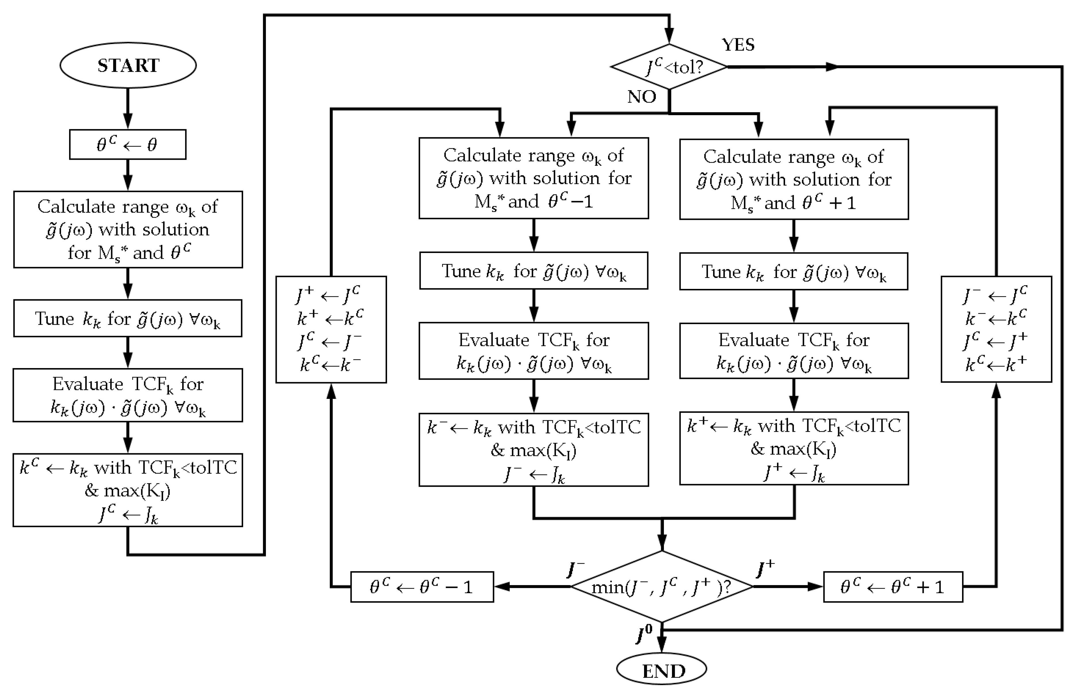
The proposed method receives as inputs the desired sensitivity margin M s i * and angle θi for the loop i, the frequency response array of the EOP and the time constant ratio β for the PID controller of this loop. As outputs, the method provides the PID controller k i C that minimizes the cost index (30) in loop i using the design frequency ωk. It also provides the relaxed angle θ i C to be used in the next iteration. Figure 6 shows the flow diagram of the proposed algorithm. It is almost the same one depicted in Figure 5 with some differences and it is described in a similar way below:
  • First, the current relaxed angle θC is initialized to the original one θ. This angle θC will be relaxed if needed and will be provided as an algorithm output.
  • Given the g ˜ ( j ω ) , obtain the design range of frequencies ωk, which allows one to find a solution for the PID control tuning given the sensitivity margin M s * and angle θC according to the argument condition in (10). For this, it is necessary to calculate the magnitude and phase of L(jω) at the tangency point by means of (16) and (17).
  • Calculate a PID controller kk for each frequency ωk using M s * and θC as specifications. First, the argument and phase to be provided by the controller are computed from (18); then, using expressions in (15), a set of PID controllers is obtained as large as the size of the design frequency array.
  • Evaluate the tangency condition function TCFk in (19) for each k k ( j ω ) g ˜ ( j ω ) . Among all designs with TFCk below a user-defined tolerance tolTC, the one with maximum integral gain KI for improving load disturbance rejection is selected. This defines the PID controller kC. The sensitivity margin Ms of k C ( j ω ) g ˜ ( j ω ) is evaluated and the corresponding cost index JC is calculated using (30).
  • If the cost index JC is below a user-defined tolerance, the specification M s * is achieved with the original angle θ, the current PID control design is acceptable, and the algorithm ends without relaxing the angle θC. Otherwise it is necessary to enter in the main part of the flow diagram, which decides how to relax this angle.
  • In similar way to the algorithm proposed in Section 3.3, the procedure needs more information to whether the relaxed angle θC must be incremented or decremented. Therefore, steps from 2 to 4 are repeated for θC+ 1 and θC − 1. The left branch performs the PID designs for θC − 1 obtaining the PID controller k and its corresponding cost index J. The right branch develops the PID designs for θC + 1 providing the PID controller k+ with the corresponding cost index J+.
  • Determine the search path by means of the three cost indices J, JC and J+. There are three possibilities:
    • If JC is the minimum cost index, the best solution is achieved using the current relaxed angle θC with the PID controller kC, and the procedure finishes.
    • If J+ is the minimum cost index, the tuning is improved incrementing the relaxed angle, so θC is incremented, and the process enters the loop of the right branch. Since θC has been updated, some cost indices and their corresponding PID controllers must be also updated accordingly as follows: J = JC, k = kC, JC = J+ and kC = k+. Next, the new index J+ and controller k+ are obtained following again the right branch steps.
    • If J is the minimum cost index, a decrease in θC improves the PID design, so it is decremented, and the algorithm follows the loop of the left branch. This θC modification entails the update of the following indices and associated controllers: J+ = JC, k+ = kC, JC = J and kC = k. Then, the new index J and controller k are obtained after the left branch steps.
  • The process iterates into the branch determined in the previous step until no improvement is achieved in the cost index. Then, JC results in the minimum cost index and the procedure ends. The algorithm provides as outputs the associated PID controller kC and the relaxed angle θC to be used as input in the following iteration step of the general multiloop design procedure.

3.5. Linear Margin Case

In this case, the monovariable PID tuning design is performed through a linear programming optimization as proposed in [27] for stable systems and commented in Section 2.2.2. The method uses a linear margin defined by the line r intersecting the negative real axis at the point (−1 + ℓ, 0) with an angle α and forces the Nyquist plot L(jω) to be located below this line. This ensures lower bounds on ϕm, Am and Ms. The application of this method into the proposed algorithm in Figure 4 for the multiloop PID design is straightforward. For each loop i of the n × n process G(s), the corresponding linear margin must be defined by i and αi as inputs. Once the algorithm enters the iterative procedure of the flow diagram in Figure 4, the n EOPs g ˜ i m ( j ω ) are already calculated from the previous iteration m − 1. Then, a PID controller is tuned for each EOP by means of the linear programming problem in (25). Next, the new EPO g ˜ i m + 1 ( j ω ) of each loop is updated using these new sets of PID controllers.
For each new pair k i m ( j ω ) g ˜ i m + 1 ( j ω ) the linear margin must be evaluated to quantify a cost index to decide whether the iteration process continues or not. This is the main point that differs from previous cases. There are two possible situations: (a) all points of L(jω) are below line r or (b) some points are above it. If all L(jω) points are below the line r as represented in Figure 7a, it is preferred that the Nyquist plot to be as close as possible to the line r to avoid unnecessary conservative designs. This can be measured by the shortest distance dmin of the Nyquist diagram to the line r, which is calculated selecting the minimum value of the distances of each point L(jωk) to the line r. Considering the line r equation in (24), the distance of the point L(jωk) to this line is given by (31).
d ( L ( j ω k ) , r ) = | tan α · e ( L ( j ω k ) ) + tan α · ( 1 ) m ( L ( j ω k ) ) | ( tan α ) 2 + 1
When there are some points of L(jω) above the line, as shown in Figure 7b, the linear margin is not fulfilled, and again it is desired that these points to be as close as possible to the line r. This can be measured by the greatest distance dmax of these Nyquist points to the line r, which is the maximum distance. Therefore, this work proposed to define the fitting distance D of L(jω) to line r as follows:
D = { d min = min ω k ( L ( j ω k ) , r ) i f   tan α · ( e ( L ( j ω k ) ) + 1 ) m ( L ( j ω k ) ) 0 ω k d max = max ω m ( L ( j ω m ) , r ) i f     ω m :   tan α · ( e ( L ( j ω m ) ) + 1 ) m ( L ( j ω m ) ) > 0
Using this fitting distance to the line r, the cost index defined in (33) was proposed as the sum of the fitting distances of all the loops. If its value is below a user-defined tolerance (0.002 by loop), the multiloop PID tuning is approved and the algorithm ends; otherwise, a new iteration is performed. In [30], an iterative procedure for decentralized controllers is also proposed using the linear margin in [27]; however, it performs the iterations in other way and does not use a cost index for evaluating the design or the algorithm convergence.
J = i = 1 n D i

4. Illustrative Examples

In this section, the effectiveness of the proposed methodology for tuning multiloop PID controllers is demonstrated using two simulation processes. The multivariable systems are 2 × 2 and 3 × 3 stable processes. The methodology is applied using different SISO PID tuning methods.

4.1. Wood and Berry Distillation Column

The transfer function matrix of this 2 × 2 system with time delays is given by (34). It represents a binary distillation column process with top and bottom compositions as outputs to be controlled and reflux and steam flows as manipulated inputs [31]. This is a classical testbench in the multivariable control. The time constants and delays are expressed in minutes. The process RGA in the stationary state is shown in (35) and the diagonal positive elements recommend a diagonal input–output paring. A frequency response array of 1000 elements is calculated within the frequency range [10−5, 10] rad/s.
G W B ( s ) = ( 12.8 16.7 s + 1 e s 18.9 21 s + 1 e 3 s 6.6 10.9 s + 1 e 7 s 19.4 14.2 s + 1 e 3 s )
R G A = ( 2 1 1 2 )
Five decentralized controllers are designed to verify the proposed methodology with the five SISO PID tuning methods described in Section 3. The required specifications in each case are the following ones:
  • Phase margin case: ϕm = 45° in both loops.
  • Gain margin case: Am = 3 in both loops.
  • Combined phase margin and gain margin case: ϕm = 45° and Am = 3 in both loops.
  • Sensitivity margin case: Ms = 1.68 and initial θ = 25° in both loops.
  • Linear margin case: = 0.67 and α = 62° in both loops.
In each case, the PI controllers are firstly attempted to achieve the desired specifications. If they are not reached, it is checked whether the decentralized design is improved using PID controllers. A time constant ratio β = 0.1 is set for the PID control. Table 1 collects the PID controllers obtained in each case with the procedures proposed in this work. The provided PID parameters are those of the parallel PID structure in (21). The table also shows the obtained specifications of phase margin, gain margin, sensitivity margin and the phase margin crossover frequency, which is usually close to the loop bandwidth. PI controllers are enough for the phase margin case and sensitivity margin case. In all cases, the requirements are practically achieved in both loops. In the third design, the obtained phase margin for the second loop is 46° instead of 45°, but it is very close.
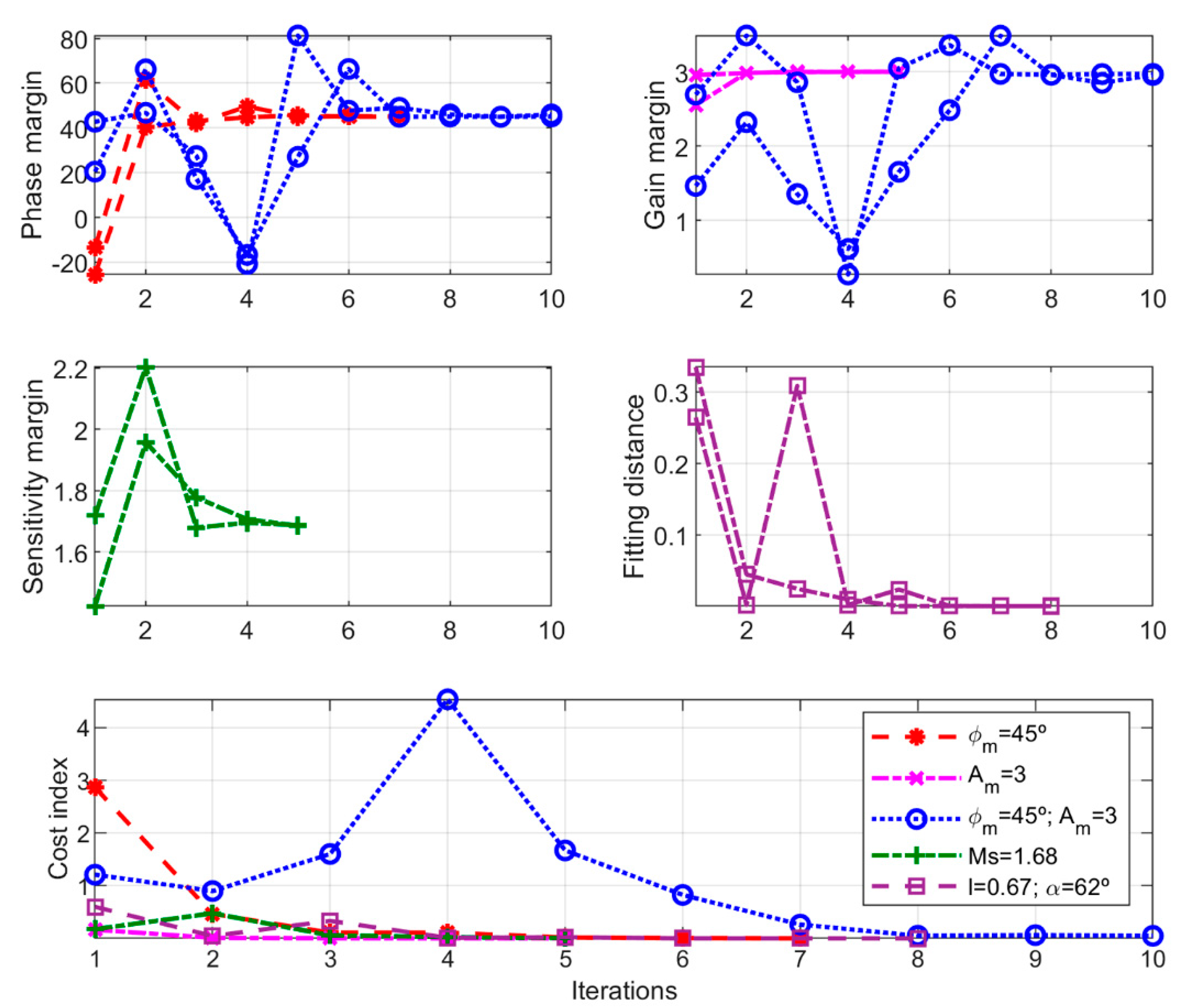
Figure 8 displays the PID parameter values through the iteration procedure in each case. Correspondingly, Figure 9 shows how the required specifications were achieved and the cost index decreased and converged reaching a value below the user-defined tolerance. The designs were obtained between 5 and 10 iterations, being most of them very close to the final values after four iterations. The case of phase and gain margin combination shows the slowest convergence. The cases of phase margin and sensitivity margin were the fastest ones, which was logical since these cases used PI controllers and had fewer tuning parameters.
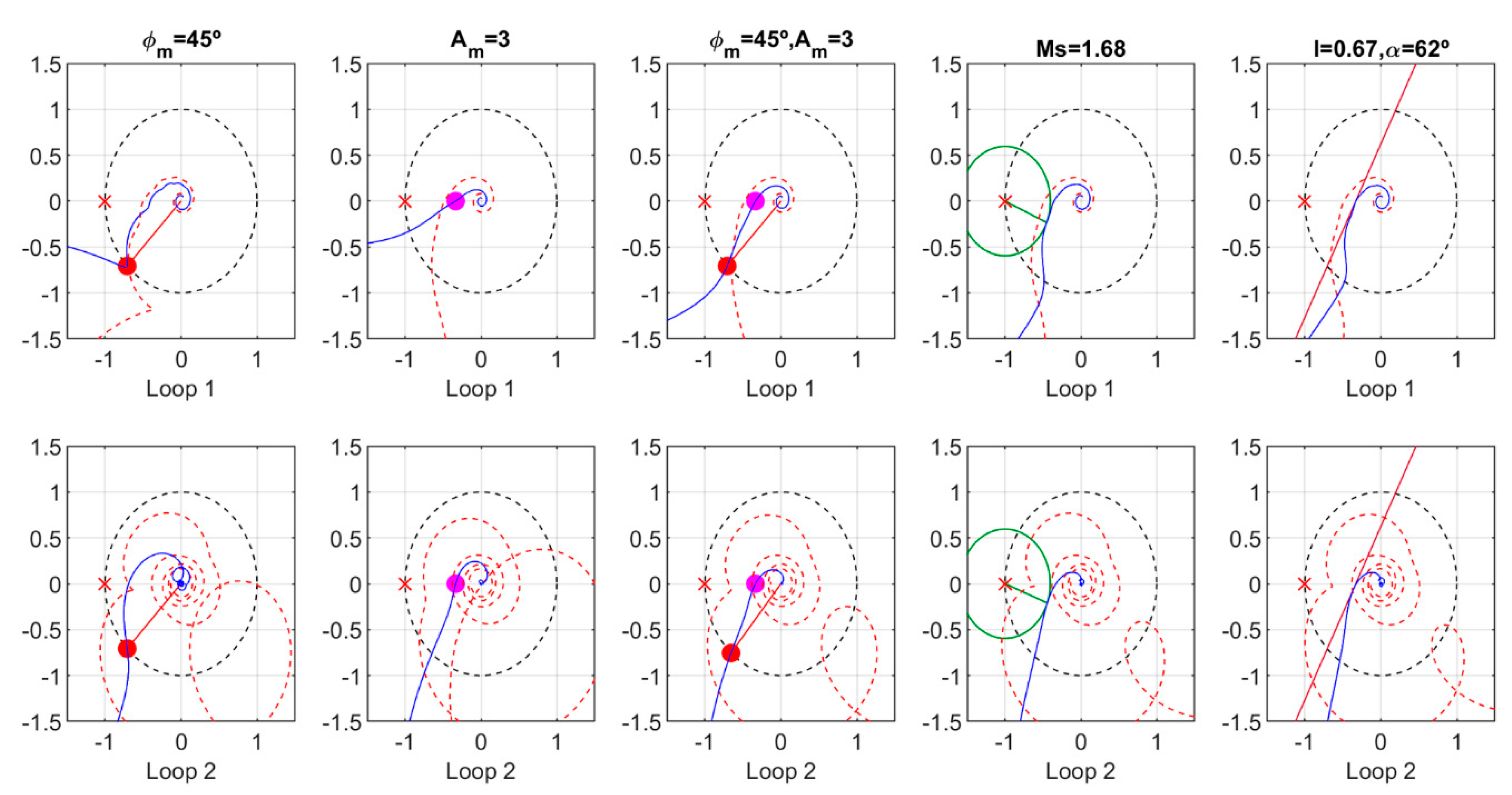
The resultant Nyquist diagrams of the proposed designs are illustrated in Figure 10, where each column corresponds to the two loops of each case.
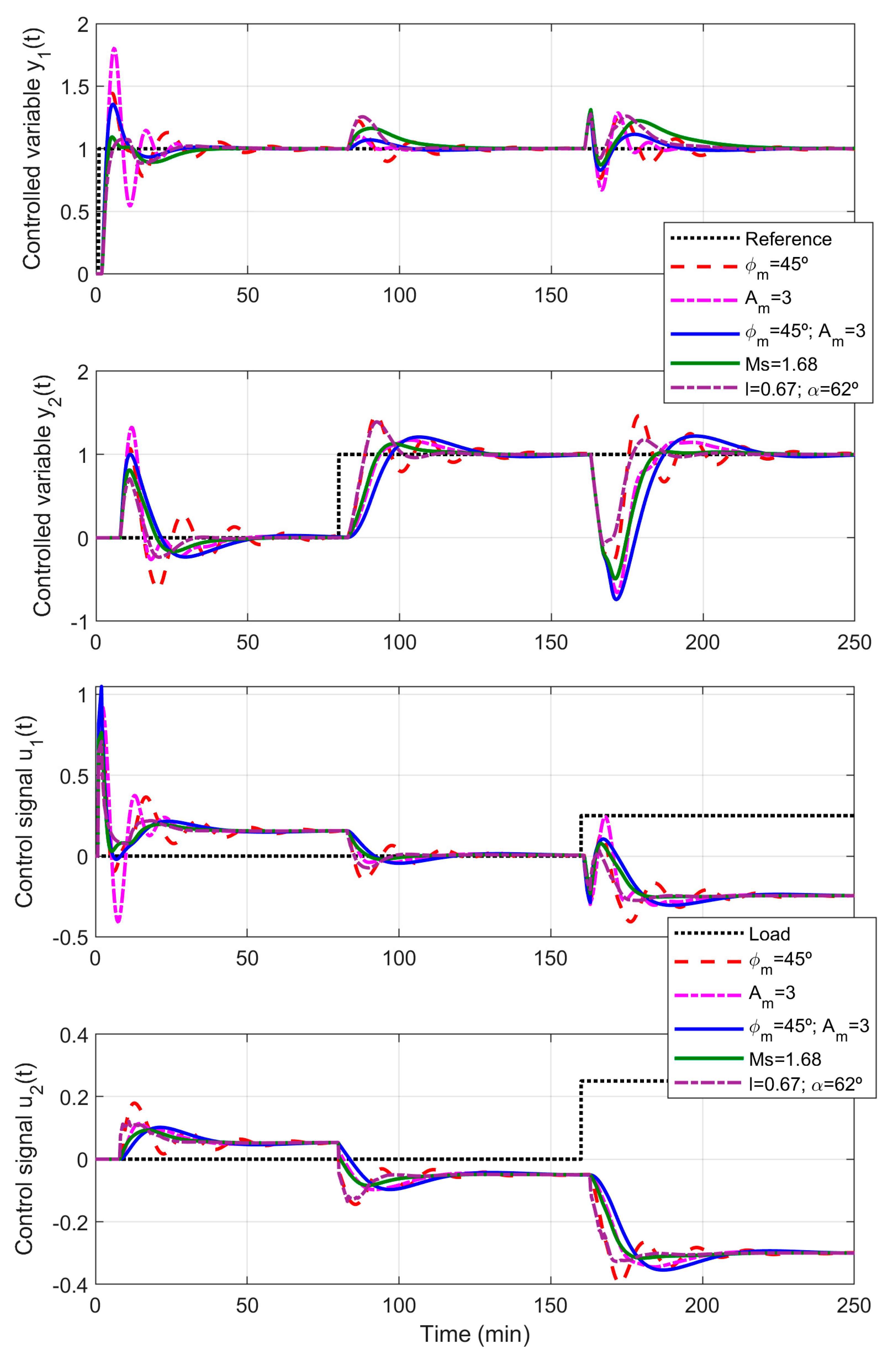
The closed loop system responses of the proposed decentralized controllers are shown in Figure 11. Unit step changes were applied at t = 1 min in the first reference and at t = 80 min, in the second one. There were also a 0.25 step change in both inputs as load disturbance at t = 160 min. In the performed simulations, the PID controllers were implemented using a PI-D structure, where the control signal was calculated according to (36) and the derivative action is filtered by a first order term with N = 20 [32]. The effect of this filter in the frequency response was neglected into the frequency range of interest.
u ( s ) = ( K P + 1 K I s ) e ( s ) K P T D s T D N s + 1 y ( s )
The integrated absolute errors (IAEs) of each simulation case and the total variation (TV) of the control signals were calculated. They are shown in the last two columns of Table 1. The worst two cases were the designs obtained only for the phase margin or only for the gain margin. They show a more oscillatory response and higher IAE and TV values. The multiloop PI controller achieved with only the phase margin as a requirement had a low value of gain margin in the second loop. In a similar way, the design performed only with gain margin as specification achieved a low phase margin in the first loop. This resulted in a poorer performance of the control system.
This situation was improved using the combined specification of gain margin and phase margin, the sensitivity margin, or the linear margin. These three cases ensured lower bound values of the gain margin and phase margin. The proposed controllers of the last two cases were quite similar and they achieved the best performance with lower values of IAE and TV. The proposal obtained for the combination of ϕm and Am had a good response for reference step changes; however, the bandwidth of its second loop was a bit low, which resulted in a slow load disturbance rejection and a high IAE value in the corresponding loop.

4.2. Ogunnaike and Ray Distillation Column

The transfer matrix of this 3 × 3 distillation column process is given by (37) in [33], where delays and time constants are expressed in minutes. According to its stationary RGA, which is shown in (38), a diagonal input–output paring is recommended since the diagonal elements were positive and close to the unity. From this model, a frequency response array of 1000 elements is obtained within the frequency range from 10−5 to 10 rad/s.
G O R ( s ) = ( 0.66 6.7 s + 1 e 2.6 s 0.61 8.64 s + 1 e 3.5 s 0.0049 9.06 s + 1 e s 1.11 3.25 s + 1 e 6.5 s 2.36 5 s + 1 e 3 s 0.01 7.09 s + 1 e 1.2 s 34.68 8.15 s + 1 e 9.2 s 46.2 10.9 s + 1 e 9.4 s 0.87 ( 11.61 s + 1 ) ( 3.89 s + 1 ) ( 18.8 s + 1 ) e s )
R G A = ( 2 0.72 0.28 0.64 1.82 0.18 0.36 0.10 1.46 )
The proposed methodology was applied to this process using PI controllers and using two different specifications: firstly, with the sensitivity margin (proposed 1), and secondly, with the linear margin (proposed 2). The values specified for these requirements in each loop and the corresponding achieved robustness margins were collected in Table 2. Figure 12 shows the evolution of the PI parameters, the required specifications and the cost index value for each iteration. Proposal 1 converged after four iterations and the second one, after six. The resultant Nyquist diagrams of each loop are illustrated in Figure 13, where the first row corresponds to proposal 1 and the second one, to proposal 2.
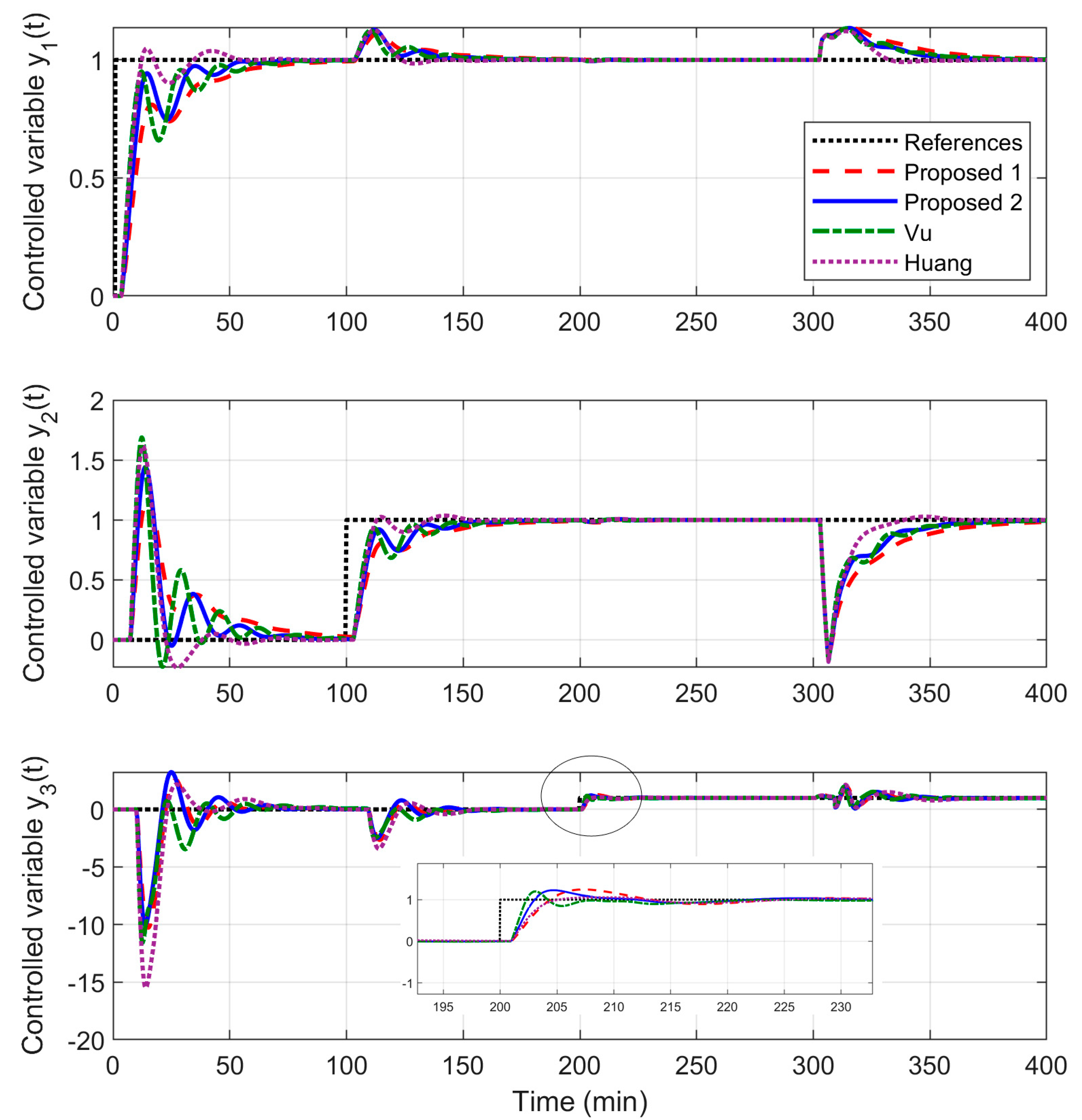
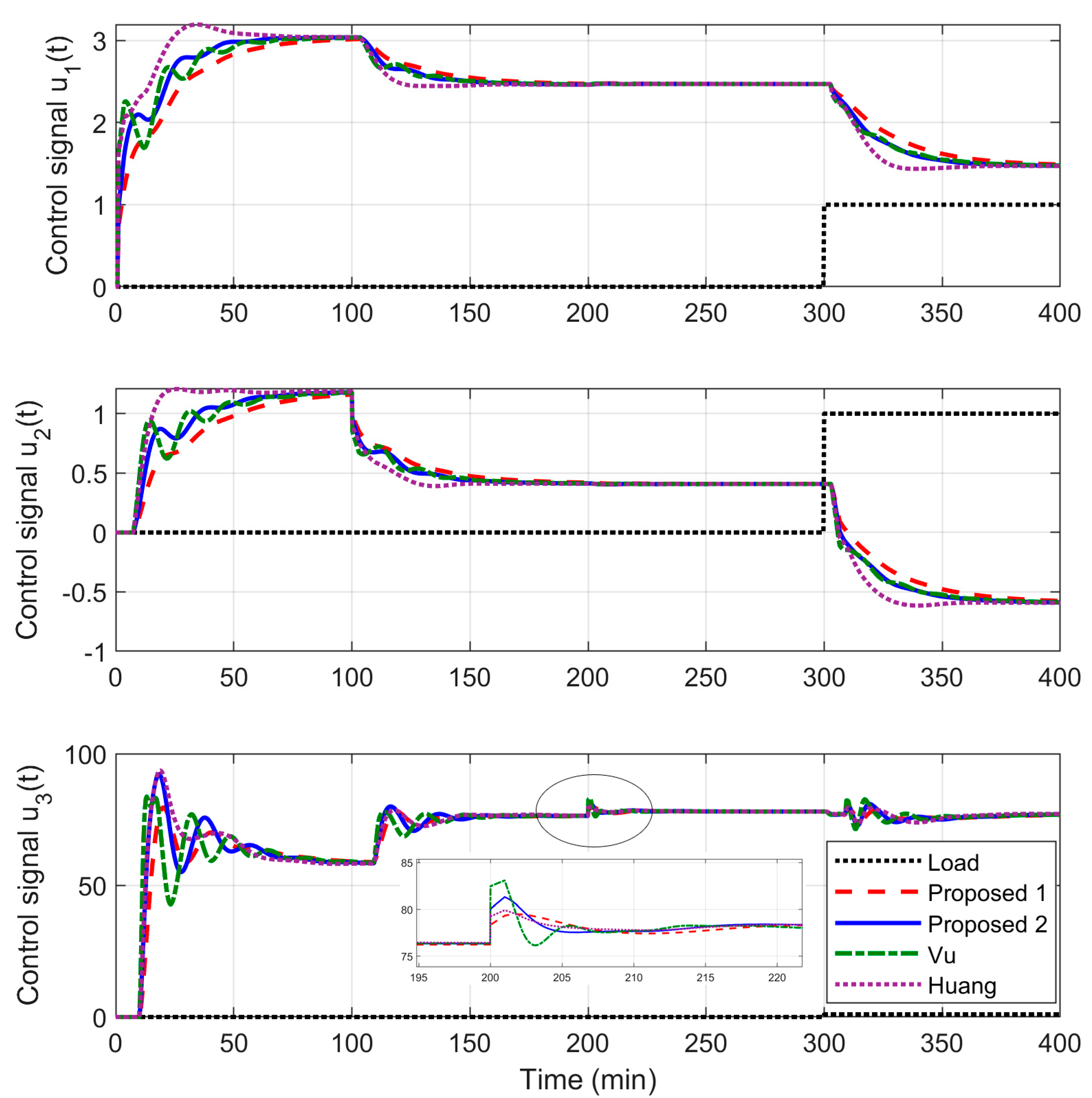
In comparison with example 1, which has been used to illustrate the majority of aspects and cases of the proposed methodology, the proposals for example 2 were limited only to these two cases because the obtained multiloop PI controllers were compared with two decentralized controllers proposed by other authors: the multiloop PI control of Vu in [19] and the multiloop PID control of Huang in [18]. Figure 14 and Figure 15 show a comparison of the closed loop system responses where unit step changes were applied at t = 1 min in the first set-point, at t = 100 min, in the second one and at t = 200 min, in the third one. A unit step change was also applied in all inputs at t = 400 min as load disturbance. Figure 14 details the time response of the controlled variables while Figure 15 shows the control signals. Table 2 indicates the IAE values and TV values obtained by the four designs. It also includes the robustness margins obtained with the controllers proposed by the other authors.
The two proposed multiloop PI controllers had a better performance than that obtained by the decentralized PI control of Vu, which shows the highest TV values. The multiloop PID control of Huang achieved the lowest IAE values in loop 1 and 2 at the expense of a worse response of the loop 3 with a higher IAE value and a great interaction from loop 1.

5. Conclusions

An iterative multiloop PID tuning methodology for multivariable square and stable processes with multiple time delays was developed in this work. The iterative procedure consists of the following steps: a decomposition of the systems into separate SISO loops by means of the concept of effective open loop processes; the tuning of each PID controller for the corresponding EOP using a robustness margin in the frequency domain; and recalculation of EOPs with these new controllers and evaluation of the achieved specifications by a cost index. Due to the use of EOPs, the interaction from other loops and the full information of the multivariable process model are considered for tuning each PID controller. Since the EOP transfer functions can result in very complicated or irrational expressions, the proposed method is based on a frequency response matrix representation to avoid approximations or reductions of the EOPs. For this reason, the proposed SISO PID tuning methods to be used in the iterative design procedure are based on this kind of representation and robustness specifications in the frequency domain. The following cases were described and analyzed:
  • Phase margin or gain margin cases: the proposed SISO PID tuning method is based on moving a point of the EOP Nyquist diagram to a desired one of the open loop L(jω) fulfilling the specified margin and providing the maximum possible integral gain.
  • Combined phase margin and gain margin case: a new PID tuning method is proposed based on the previous cases. Since achieving both margins simultaneously is not always possible, this method relaxes the phase margin specification in one direction by means of an iterative path-following algorithm until no improvement is achieved in a defined cost index that combines both margins.
  • Sensitivity margin case: a new PID tuning method is also proposed for this case. It is based again on moving a point of the Nyquist diagram to fulfill the specification. The algorithm receives as inputs the sensitivity margin Ms and angle θ at the tangency point, which can be relaxed in similar way to the previous case. In the method this angle is relaxed if needed to achieve a suitable design fulfilling properly the tangency condition and maximizing the integral gain.
  • Linear margin case: the proposed PID tuning method performs a loop shaping of L(jω) approaching it as a linear optimization problem. It ensures that the Nyquist diagram of L(jω) is below a line r and maximizes the integral gain. In this work a new cost index based on the distance of the Nyquist plot to the line r is proposed to determine when the algorithm ends.
The different cases were illustrated through two simulations examples. The results were compared with other works and the proposed methodology obtained similar or better performance. The best results were achieved when the sensitivity margin or linear margin were used as specifications. In addition, they usually require less iterations for the design. The main disadvantage of the proposed iterative procedure is that convergence is not always ensured. In this work the iteration process ended when the cost index associated to the specifications was below a user-defined tolerance, the cost index did not change in three consecutive iterations, or a maximum number of iterations was reached. However, the proposed methods work properly in most tested processes achieving the required specifications or others close to them.

Author Contributions

Conceptualization, F.V., J.G. and F.M.; methodology, F.V. and J.G.; software, J.G. and F.V.; validation, M.L.R.; formal analysis, M.L.R.; writing—original draft preparation, J.G.; supervision, F.M.; funding acquisition, F.V. All authors have read and agreed to the published version of the manuscript.

Funding

This research was funded by the Autonomous Government of Andalusia (Spain), grant number P18-TP-2040.

Data Availability Statement

The data presented in this study are available in the article.

Conflicts of Interest

The authors declare no conflict of interest.

References

  1. Garrido, J.; Ruz, M.L.; Morilla, F.; Vázquez, F. Interactive tool for frequency domain tuning of PID controllers. Processes 2018, 6, 197. [Google Scholar] [CrossRef] [Green Version]
  2. Bristol, E. On a new measure of interaction for multivariable process control. IEEE Trans. Autom. Control 1966, 11, 133–134. [Google Scholar] [CrossRef]
  3. Garrido, J.; Vázquez, F.; Morilla, F. Multivariable PID control by decoupling. Int. J. Syst. Sci. 2016, 47, 1054–1072. [Google Scholar] [CrossRef]
  4. Garrido, J.; Vázquez, F.; Morilla, F.; Normey-Rico, J.E. Smith predictor with inverted decoupling for square multivariable time delay systems. Int. J. Syst. Sci. 2016, 47, 374–388. [Google Scholar] [CrossRef] [Green Version]
  5. Luyben, W.L. Simple Method for Tuning SISO Controllers in Multivariable Systems. Ind. Eng. Chem. Process Des. Dev. 1986, 25, 654–660. [Google Scholar] [CrossRef]
  6. Chiu, M.S.; Arkun, Y. A methodology for sequential design of robust decentralized control systems. Automatica 1992, 28, 997–1001. [Google Scholar] [CrossRef]
  7. Hovd, M.; Skogestad, S. Sequential design of decentralized controllers. Automatica 1994, 30, 1601–1607. [Google Scholar] [CrossRef]
  8. Wang, Q.-G.; Lee, T.-H.; Zhang, Y. Multi-Loop Version of the Modified Ziegler-Nichols Method. IFAC Proc. Vol. 1999, 32, 6848–6853. [Google Scholar] [CrossRef]
  9. Mahapatro, S.R.; Subudhi, B. A Robust Decentralized PID Controller Based on Complementary Sensitivity Function for a Multivariable System. IEEE Trans. Circuits Syst. II Express Briefs 2020, 67, 2024–2028. [Google Scholar] [CrossRef]
  10. Bao, J.; Forbes, J.F.; McLellan, P.J. Robust multiloop PID controller design: A successive semidefinite programming approach. Ind. Eng. Chem. Res. 1999, 38, 3407–3419. [Google Scholar] [CrossRef]
  11. Boyd, S.; Hast, M.; Åström, K.J. MIMO PID tuning via iterated LMI restriction. Int. J. Robust Nonlinear Control 2016, 26, 1718–1731. [Google Scholar] [CrossRef]
  12. Morales, D.C.; Jiménez-Hornero, J.E.; Vázquez, F.; Morilla, F. Educational tool for optimal controller tuning using evolutionary strategies. IEEE Trans. Educ. 2012, 55, 48–57. [Google Scholar] [CrossRef]
  13. Reddy, M.D.L.; Padhy, P.K.; Ahmad Ansari, I. Auto-tuning method for decentralized PID controller of TITO systems using firefly algorithm. In Proceedings of the 2019 International Conference on Intelligent Computing and Control Systems (ICCS), Madurai, India, 15–17 May 2019; pp. 683–688. [Google Scholar] [CrossRef]
  14. Vu, T.N.L.; Lee, J.; Lee, M. Design of multi-loop PID controllers based on the generalized IMC-PID method with Mp criterion. Int. J. Control. Autom. Syst. 2007, 5, 212–217. [Google Scholar]
  15. He, M.J.; Cai, W.J.; Wu, B.F. Design of decentralized IMC-PID controller based on dRI analysis. AIChE J. 2006, 52, 3852–3863. [Google Scholar] [CrossRef]
  16. Chen, D.; Seborg, D.E. Design of decentralized PI control systems based on Nyquist stability analysis. J. Process Control 2003, 13, 27–39. [Google Scholar] [CrossRef]
  17. Zhang, Y.; Wang, Q.-G.; Astrom, K.J. Dominant pole placement for multi-loop control systems. Automatica 2002, 38, 1213–1220. [Google Scholar] [CrossRef]
  18. Huang, H.P.; Jeng, J.C.; Chiang, C.H.; Pan, W. A direct method for multi-loop PI/PID controller design. J. Process Control 2003, 13, 769–786. [Google Scholar] [CrossRef]
  19. Vu, T.N.L.; Lee, M. Multi-loop PI controller design based on the direct synthesis for interacting multi-time delay processes. ISA Trans. 2010, 49, 79–86. [Google Scholar] [CrossRef]
  20. Nandong, J.; Zang, Z. Multi-loop design of multi-scale controllers for multivariable processes. J. Process Control 2014, 24, 600–612. [Google Scholar] [CrossRef] [Green Version]
  21. Nie, Z.-Y.; Wang, Q.-G.; Wu, M.; He, Y. Tuning of multi-loop PI controllers based on gain and phase margin specifications. J. Process Control 2011, 21, 1287–1295. [Google Scholar] [CrossRef]
  22. Vázquez, F.; Morilla, F.; Dormido, S. An iterative method for tuning decentralized PID controllers. IFAC Proc. Vol. 1999, 32, 1501–1506. [Google Scholar] [CrossRef]
  23. Morilla, F.; Dormido, S. Methodologies for the Tuning of PID Controllers in the Frequency Domain. IFAC Proc. Vol. 2000, 33, 147–152. [Google Scholar] [CrossRef]
  24. Ho, W.K.; Lee, T.H.; Gan, O.P. Tuning of Multiloop PID Controllers Based on Gain and Phase Margins Specifications. IFAC Proc. Vol. 1996, 29, 6007–6012. [Google Scholar] [CrossRef]
  25. Zhu, Z.X. Structural analysis and stability conditions of decentralized control systems. Ind. Eng. Chem. Res. 1996, 35, 736–745. [Google Scholar] [CrossRef]
  26. Vilanova, R.; Alfaro, V.M. Control PID Robusto: Una visión panorámica. RIAI Rev. Iberoam. Autom. E Inform. Ind. 2011, 8, 141–158. [Google Scholar] [CrossRef] [Green Version]
  27. Karimi, A.; Kunze, M.; Longchamp, R. Robust controller design by linear programming with application to a double-axis positioning system. Control Eng. Pract. 2007, 15, 197–208. [Google Scholar] [CrossRef]
  28. Dormido, S.; Morilla, F. Tuning of PID Controllers Based on Sensitivity Margin Specification. In Proceedings of the 5th Asian Control Conference (IEEE Cat. No.04EX904), Melbourne, Victoria, Australia, 20–23 July 2004; pp. 486–491. [Google Scholar]
  29. Vu, T.N.L.; Lee, M. Independent Design of Multi-loop PI/PID Controllers for Multi-delay Processes. World Acad. Sci. Eng. Technol. 2009, 703–708. [Google Scholar] [CrossRef]
  30. Euzébio, T.A.M.; Yamashita, A.S.; Pinto, T.V.B.; Barros, P.R. SISO approaches for linear programming based methods for tuning decentralized PID controllers. J. Process Control 2020, 94, 75–96. [Google Scholar] [CrossRef]
  31. Wood, R.K.; Berry, M.W. Terminal composition control of a binary distillation column. Chem. Eng. Sci. 1973, 28, 1707–1717. [Google Scholar] [CrossRef]
  32. Åström, K.J.; Hägglund, T. Advanced PID Control; ISA-The Instrumentation, Systems, and Automation Society: Research Triangle Park, NC, USA, 2005. [Google Scholar]
  33. Ogunnaike, B.A.; Lemaire, J.P.; Morari, M.; Ray, W.H. Advanced multivariable control of a pilot-plant distillation column. AIChE J. 1983, 29, 632–640. [Google Scholar] [CrossRef]
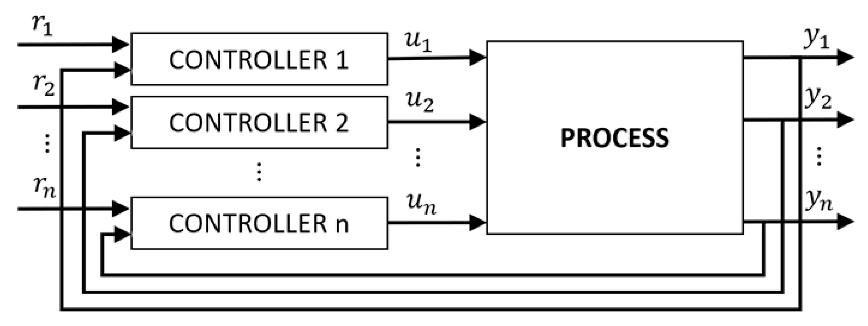
Figure 1. Multiloop control scheme.
Processes 09 00140 g001
Figure 2. Structural decomposition.
Processes 09 00140 g002
Figure 3. Robustness margins in the Nyquist diagram.
Processes 09 00140 g003
Figure 4. Flow diagram of the proposed algorithm for tuning multiloop PID controllers.
Processes 09 00140 g004
Figure 5. Flow diagram of the proposed single input single output (SISO) proportional-integral-derivative (PID) tuning algorithm for combined specification of phase margin ϕm* and gain margin Am*.
Processes 09 00140 g005
Figure 6. Flow diagram of the proposed SISO PID tuning algorithm for a specified sensitivity margin.
Processes 09 00140 g006
Figure 7. Different cases evaluating the linear margin and determining the fitting distance of the Nyquist plot L(jω) to the line r: (a) all points of L(jω) are below the line r and (b) some points of L(jω) are above line r.
Processes 09 00140 g007
Figure 8. Changes of PID parameters through the proposed iterative procedure for different specifications in example 1.
Processes 09 00140 g008
Figure 9. Progression of the design specifications and cost index through the proposed procedure in example 1.
Processes 09 00140 g009
Figure 10. Nyquist diagrams obtained with the proposed controllers in example 1 (each column corresponds to one design). The effective open loop process (EOP) is in a dashed red line and the loop (EOP with controller) in a solid blue line.
Processes 09 00140 g010
Figure 11. Closed loop system responses of proposed decentralized controllers in example 1.
Processes 09 00140 g011
Figure 12. Evolution of PI parameters, required specifications and cost index through the proposed iterative procedure in example 2.
Processes 09 00140 g012
Figure 13. Nyquist diagrams obtained with the proposed controllers in example 2 (first row for proposal 1 and second row for proposal 2). The EOP is in the dashed red line and the loop (EOP with PI controller) in the solid blue line.
Processes 09 00140 g013
Figure 14. Closed loop system responses of controlled variables in example 2.
Processes 09 00140 g014
Figure 15. Closed loop system responses of control signals in example 2.
Processes 09 00140 g015
Table 1. Proposed multiloop PID controllers and their corresponding robustness and performance indices for example 1.
Specifications in Both LoopsKPKIKDϕmAmMsωcp (rad/min)IAETV
ϕm = 45°loop 10.7320.2060452.52.240.5713.35.85
loop 2−0.0888−0.0290451.53.40.2342.61.74
Am = 3loop 10.5640.37440.08518.333.30.6110.95.43
loop 2−0.025−0.0172−0.003649.631.590.1242.30.74
ϕm = 45° and Am = 3loop 10.80660.24180.2745.12.971.60.658.13.9
loop 2−0.0018−0.01380.0462.961.680.154.20.75
Ms = 1.68loop 10.7140.0512061.72.81.6870.5112.32.82
loop 2−0.0418−0.0161055.62.91.6850.1334.90.59
= 0.67 and α = 62°loop 10.650.0640.2659.43.21.490.4510.52.72
loop 2−0.093−0.032−0.17647.23.61.680.2225.50.89
Table 2. Proposed multiloop PID controllers and their corresponding robustness and performance indices in example 2.
Specifications in Each LoopKPKIKDϕmAmMsωcp (rad/min)IAETV
Ms1 = 1.5loop 10.70.194088.24.21.510.1323.44.6
Ms2 = 1.5loop 2−0.17−0.047090.94.21.50.1361.52.9
Ms3 = 1.5loop 32.10.985043.14.71.50.37157177
1 = 0.6, α1 = 65°loop 10.9560.278061.431.830.216.74.9
2 = 0.6, α2 = 65°loop 2−0.221−0.065063.731.830.1946.43.2
3 = 0.6, α3 = 65°loop 31.391.105056.32.51.780.6151256
Multiloop PI
(Vu, 2010)
loop 11.570.263065.22.61.960.2417.56.3
loop 2−0.31−0.064075.32.41.960.247.34
loop 36.10.635047.51.92.250.85163.6318
Multiloop PID (Huang, 2003)loop 11.990.4587.49744.64.41.590.212.25.1
loop 2−0.422−0.098−1.288433.81.770.1936.93.2
loop 32.8250.6740.01759.23.91.460.37214197
Publisher’s Note: MDPI stays neutral with regard to jurisdictional claims in published maps and institutional affiliations.