Article

A SAR Micromixer for Water-Water Mixing: Design, Optimization, and Analysis

by
Md. Readul Mahmud
1,
Shakhawat Hossain
2,* and
Jin-Hyuk Kim
3,4,*
1
Department of Physical Sciences, Independent University Bangladesh, Dhaka 1229, Bangladesh
2
Department of Industrial and Production Engineering, Jashore University of Science and Technology, Jessore 7408, Bangladesh
3
Carbon Neutral Technology R&D Department, Korea Institute of Industrial Technology, Cheonan 31056, Korea
4
Industrial Technology (Green Process and Energy System Engineering), KITECH School, University of Science and Technology, Daejeon 34113, Korea
*
Authors to whom correspondence should be addressed.
Processes 2021, 9(11), 1926; https://doi.org/10.3390/pr9111926
Submission received: 23 August 2021 / Revised: 24 October 2021 / Accepted: 25 October 2021 / Published: 28 October 2021
(This article belongs to the Section Manufacturing Processes and Systems)

Abstract

:
A numerical investigation of the mixing performance and fluid flow in a new split and recombine (SAR) Y U β micromixer is presented in this work. A parameter called connecting angle βis varied from 0° to 90° to analyze the effect on the SAR process and mixing performance. Thenumerical data shows that the SAR process strongly depends on the connecting angle (β) and maximum efficiency (93%) can be achieved when the value of β is 45°. The Y U 45° the mixer also offers higher efficiency and lower pressure drop than a known SAR ‘ H C ’ mixer irrespective of Reynolds numbers. The split and recombine process, the influence of secondary flow, and pressure drop characteristics at various Reynolds numbers are also studied. In addition, mixing effectiveness is also computed, and among all examined mixers, Y U 45° is by far the best performing one.

1. Introduction

Microfluidics is a field that has gotten a lot of interest in recent years because of its many applications and quick growth [1]. On a micro-scale, a micromixer mixes fluids independent of their characteristics and nature, such as density, viscosity, and surface tension. The uses of micromixers and microreactors are increasing day by day in various applications such as chemical processes, biological reactions, medication discovery and distribution, medical diagnosis, chemical synthesis, and the food industry, etc. [2,3,4]. Rapid analysis, mobility, greater control, cheap cost, fast throughput, and spending fewer quantities of expensive reagents, are the primary advantages of micromixers over large batch reactors or mixers [5,6]. Other advantages of employing micromixers include a repeatable environment and the ability to use them for a variety of biological applications ranging from nucleic acid and protein analysis to medication development and delivery [7]. Micromixers operate typically under laminar flow at low Reynolds numbers ( R e ) where viscous forces dominate over inertial forces. Hence, molecular diffusion is the main mechanism of the mixing process inside the microchannels. To achieve acceptable mixing performance, a significant channel length and time duration are required [8].
Active and passive mixers are proposed to address these limitations. To improve the mixing process, active mixers employ a variety of external energy sources such as acoustic field, periodic pressure field, electric field, temperature field, magnetic field, and so on [9,10,11]. Passive mixers, on the other hand, lack active elements and rely on the inventive geometrical configuration to achieve high mixing performance [12]. The efficacy of active mixers is higher compared to passive mixers because of the additional active elements. Therefore, the production of active mixers is complex and difficult to incorporate into the microfluidic system [13]. Passive mixers, on the other hand, utilize various innovative geometrical shapes and sizes, different kinds of obstacles/baffles inside the microchannel, a grooved surface, or a herringbone wall, and split and recombine (SAR) process [12,14].
SAR is a technique in which fluids are repeatedly separated and recombined, resulting in different multi-laminations of fluids that enhance the interfacial area and mixing index considerably [15]. Many researchers have built and investigated SAR mixers based on various concepts. Authors have suggested unbalanced SAR mixers [16,17], SAR mixers with an obstruction or baffle have been investigated in publications [18,19], SAR mixers with a curved channel have been built and studied in [20,21,22,23], and SAR mixers with varied shaped mixing units have been reported in various works [15,24,25,26,27]. Lee et al. [28] constructed a new SAR mixer compatible with the microfabrication process of polydimethylsiloxane (PDMS). The efficiency and pressure drop are evaluated both experimentally and numerically, and the experimental outcome shows that interfaces are increased exponentially by SAR mixing. A new passive chaotic micromixer called the barrier embedded Kenics micromixer (BEKM) is presented by Kim et al. [29]. The proposed mixer provides higher efficiency compared to T-pipe and Kenics mixers but no data for mixing cost is provided. Different types of SAR mixers with combined mixing principal and complicated geometric structured ones are also reviewed by authors [3,6,12,27,30,31,32,33].
A novel H C micromixer based on the split and recombine principle is designed by Viktorov et al. [34] and examined both experimentally and numerically for Reynolds numbers starting from 1 to 100. The H C mixer provides very good efficiency (more than 90%), but the pressure drop is higher due to its long length and complex geometry. From the literature review, it can be said that generally SAR mixers incorporate splitting, reorientation, recombination, stretching, folding, vortex creation, and multi lamination processes which yield good mixing. However, complex 3D structure, complicated fabrication process, and high-pressure drop are a few disadvantages of the SAR mixers.Therefore, it is still a challenge to design a 3D SAR mixer that will provide good efficiency, low-pressure drop (or mixing cost), and is easy to fabricate.
Computational fluid dynamics (CFD) enables the analysis of various characteristics of fluid flow such as pressure-drop, velocity, vorticity, efficiency, species concentration as well as comprehensive visualization of the mixing process and related flow patterns including streamlines, vortex formation, and velocity vector [13]. Because of the fast growth of computer memory and processing time, the use of CFD is also rapidly expanding. Through visualizing the mixing and reaction process, CFD has become a cost-efficient, time-saving, and effective technique of investigating flow patterns and exploring new geometries of microreactors [8]. Therefore, more and more researchers are using CFD to design, amylase, and compare various kinds of micromixers and microreactors [35].
A 3D SAR ‘ Y U β ’ mixer is designed and investigated in this study. The mixing performance and flow characteristics are simulated by Ansys FLUENT 15 software. The ‘ Y U β ’ mixer consists of four identical elements, and each element relates to one another by an angle. The effect of connecting angle β on the mixing performance was studied. The value of the angle β is varied starting from 0° to 90°; increased 15° in each time. The split and recombine process, the influence of secondary flow, and pressure drop characteristics are analyzed numerically for the Reynolds numbers ranging from 1 to 100. To validate the numerical method and compare the performance of the proposed mixer, a known SAR H C mixer is also studied.
This paper is composed of five different segments. The literature survey describes the background of micromixers with an emphasis on SAR-type mixers. The design of the new ‘ Y U β ’ micromixers and a known H C mixer is presented in the second part (Section 2). The ‘Section 3’ section reports the validation of mesh, related equations, and detailed boundaries conditions of the numerical simulation. The ‘Section 4’ part represents various results such as efficiency, pressure drop, mixing effectiveness, etc. Lastly, the overall summary of the work is discussed in the ‘Section 5’ segment.

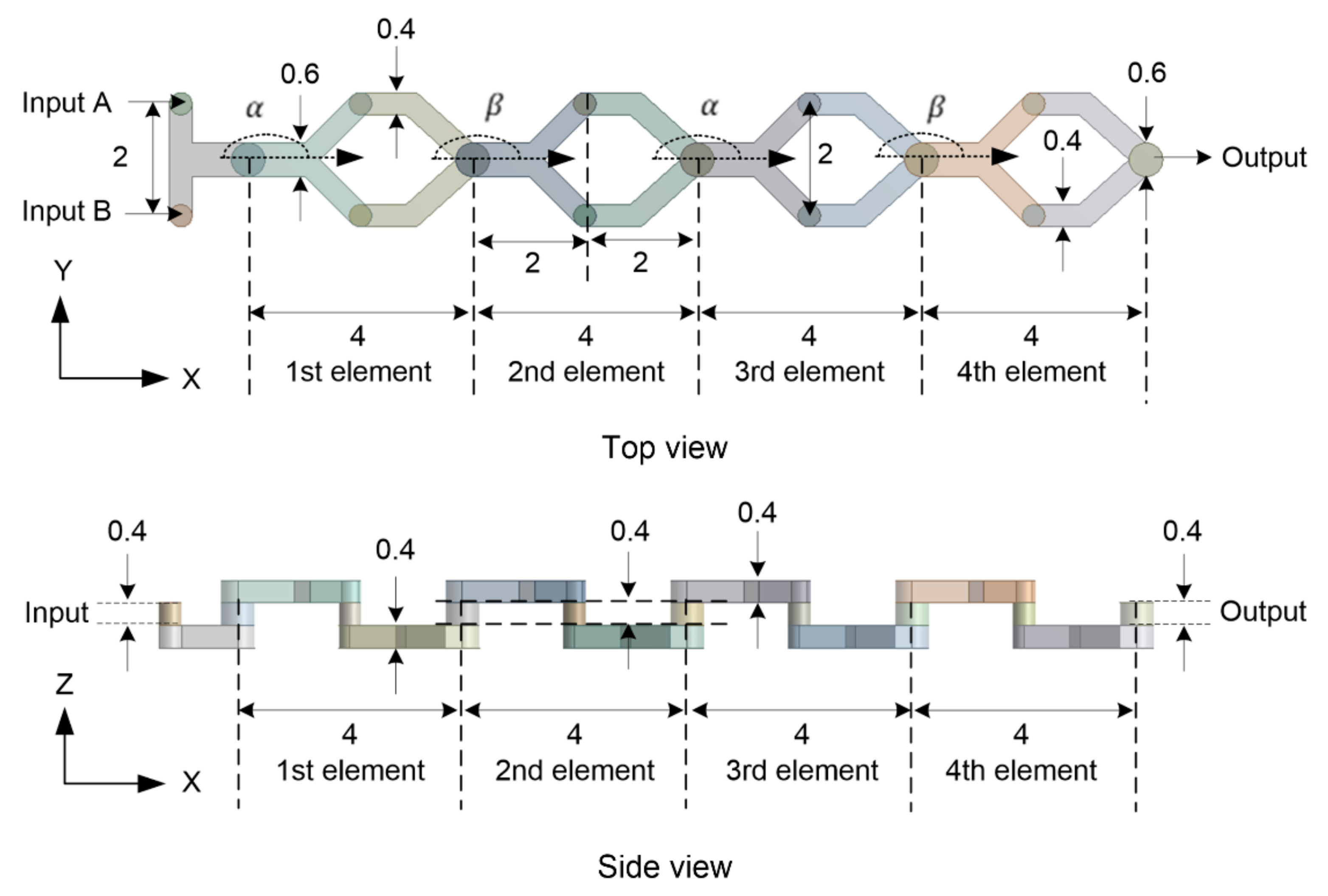
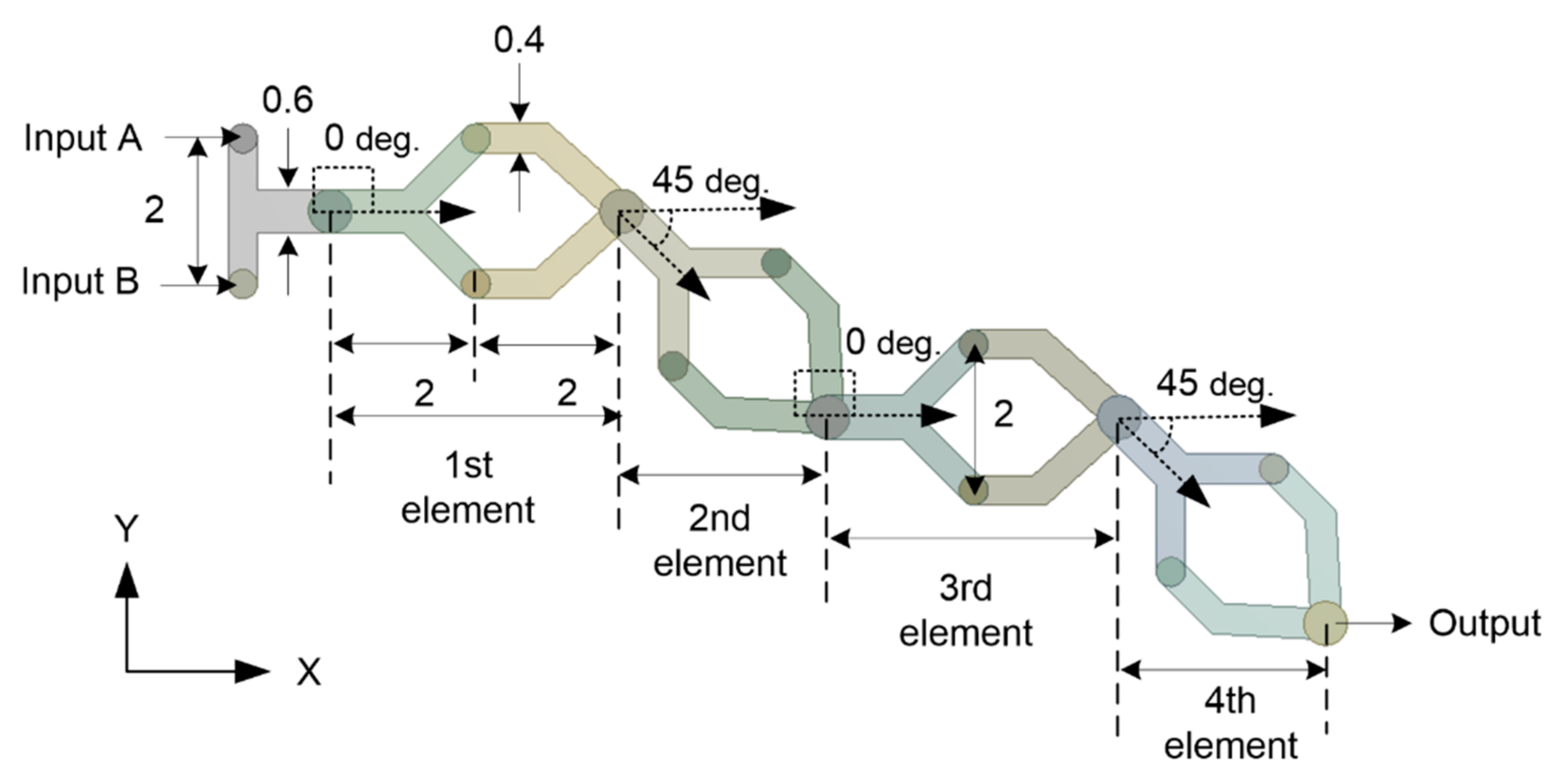
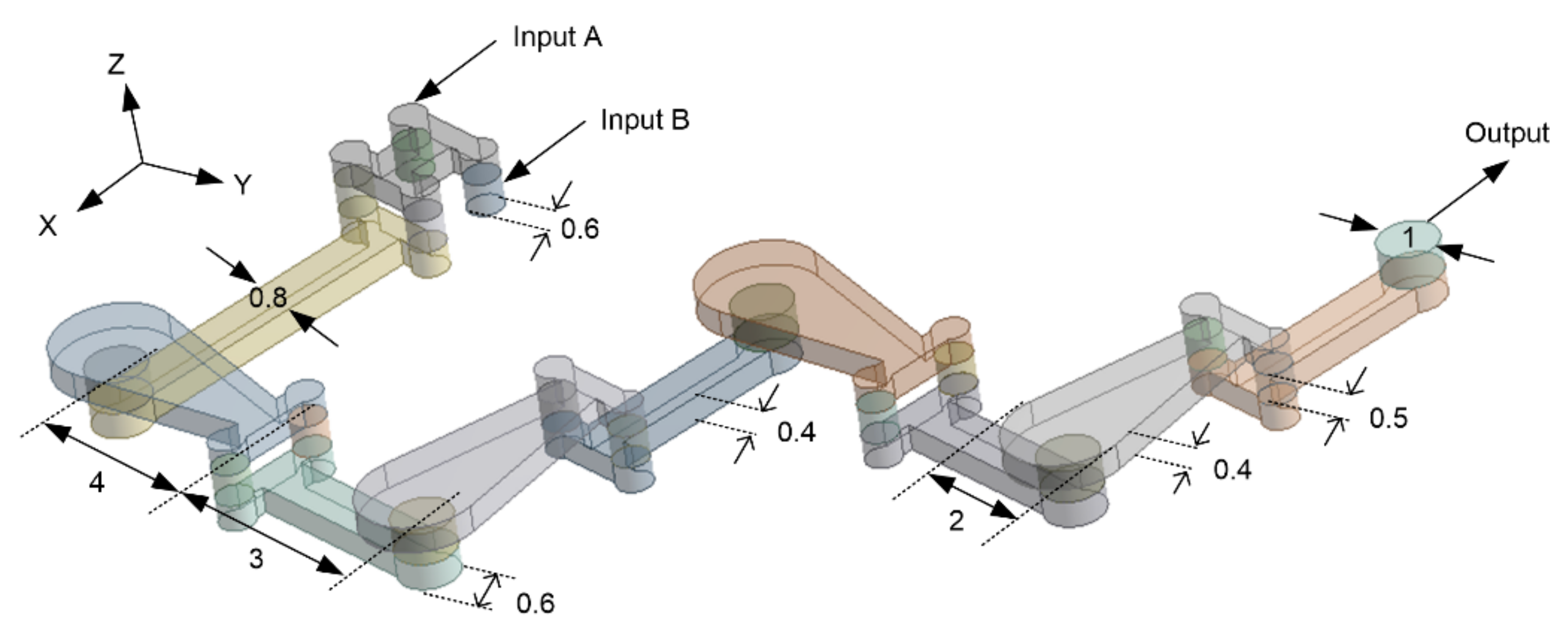
2. Micromixer Design
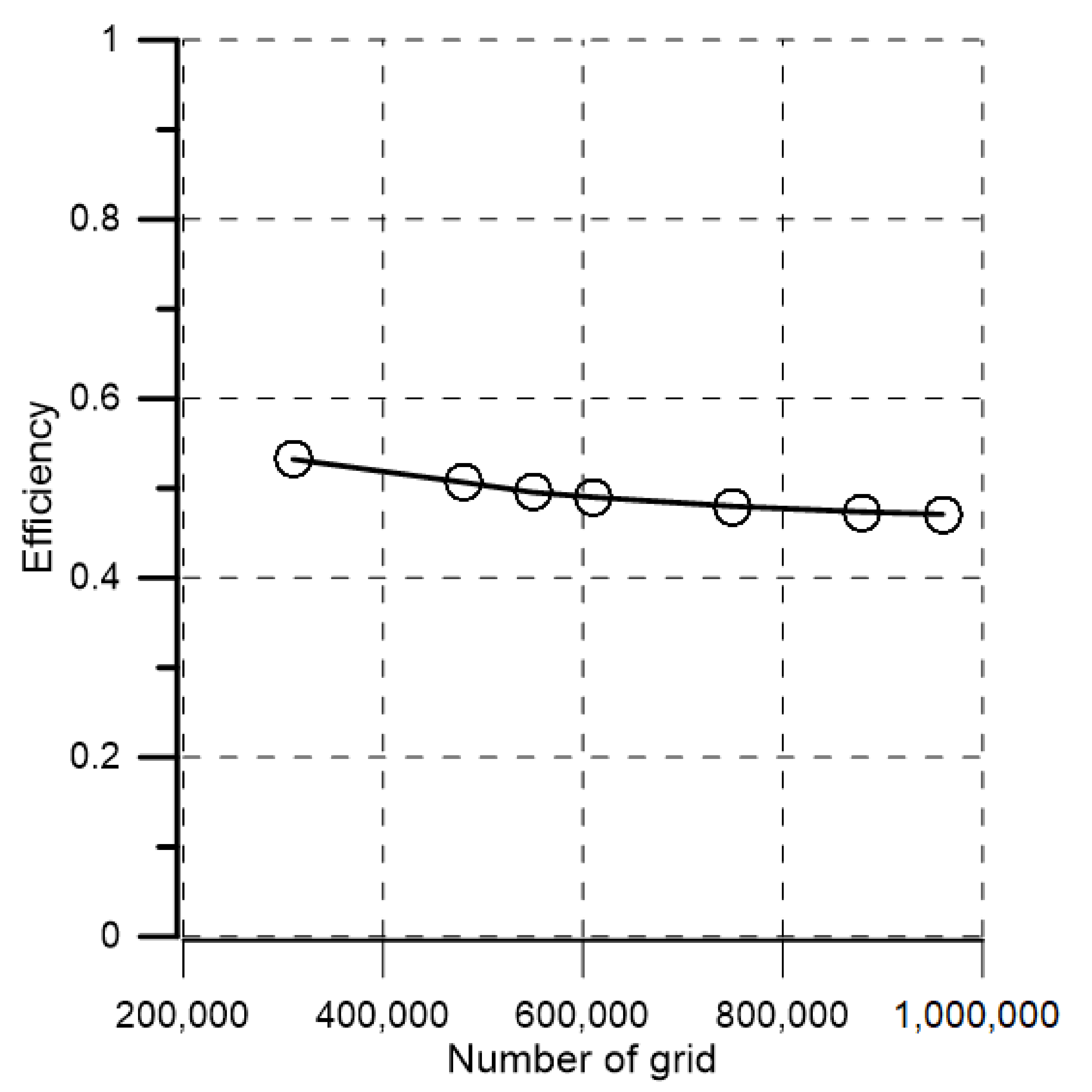
The proposed Y U β ’ mixer has four identical elements connected in series as illustrated in Figure 1. The mixer is designed using the split and recombine (SAR) principle. A single element is 2 mm long and comprises one ‘Y’ and one ‘U’ shaped segment connected by a cylinder. The height and radius of the connecting cylinder are 0.4 mm. The mixer has two inputs, namely Input A and Input B, and one output. The radius of inputs and output is 0.4 mm and 0.6 mm, respectively. The height of the mixers is always kept the same thought-out mixer and the value is 0.4 mm.
The angle of each element with the X-axis is represented by α and β as shown in Figure 1. The angle α is always kept constant with a value of 0 ° whereas angle β is changed from 0 ° to 90 ° ; increased 15 ° in each time. Therefore, there are seven ‘ Y U β ’ mixers in total with different values of angle β that are represented by Y U 0 °   β = 0 ° , Y U 15 °   β = 15 ° , Y U 30 °   β = 30 ° , Y U 45 °   β = 45 ° , Y U 60 °   β = 60 ° , Y U 75 °   β = 75 ° and Y U 90 °   β = 90 ° . Figure 2 illustrated the Y U 45 ° mixer with α = 0 °   a n d   β = 45 ° as an example.
A published SAR mixer called H C [34] is also designed and analyzed numerically to have a point of reference for comparison. The ‘ H C mixer also has four elements and the length of each element is 7 mm. The geometrical configuration of the ‘ H C ’ mixer is shown in Figure 3 with important dimensions.

3. Numerical Method

Ansys Fluent 15 was used to numerically simulate the micromixing process and flow characteristics inside the microchannel. Two fluids enter input A and input B, and exit from the output. The Reynolds numbers which indicate the flow patterns (laminar or turbulent) are calculated by the following equation [34,36].
R e = ρ V d μ
where ρ , V , μ , and d are fluid density, velocity, dynamic viscosity, and characteristic length, respectively. The minimum dimension of the micromixer in this study is 0.4 mm which is elected as characteristics length d [34]. The inlets velocity was calculated by using Equation (1) by putting corresponding values of the water. The velocity of each input is calculated as 1.25 × 10 3   m / s for R e = 1 , as an example.
The governing continuity, Navier- Stokes and convection-diffusion equations for Newtonian and incompressible fluid with constant physical properties flowing steadily as follows [20,37]:
· V = 0
ρ V · V = P + μ 2 V
V · C = D 2 C
where V , ρ , μ ,   and   P are fluid velocity, density, dynamic viscosity, and pressure, respectively. Besides, C and D are the mass concentration of the species and the coefficient of diffusion of the fluids, respectively. For finite element method-based analysis of mixing in the microchannel, pure water was assigned at input A and input B. The diffusion constant for water-water mixing is considered as 1 × 10 9   m 2 / s [38,39]. The mass concentration of two species is considered as 0 and 1 in numerical simulation. Maximum homogeneity is achieved when the species value becomes 0.5. The density, viscosity, and diffusions constant of the water is 1000   kg / m 3 , 0.001   Pa and 1 × 10 9   m 2 / s , respectively used in the calculation. A uniform velocity is provided at inputs, constant gauge pressure (zero) is used at the output and a No-slip boundary condition is imposed on all walls of the microchannels. SIMPLEC algorithm is used for pressure-velocity coupling. A second-order upwind scheme is employed to reduce the numerical diffusion. QUICK and PRESTO options are selected under solution method operation [8]. To ensure the maximum accuracy of the numerical solutions, the governing equations were solved iteratively; the convergence criterion for all values was set 1 × 10 6 . The following equations are used to compute the standard deviation and mixing efficiency [14,34].
σ = 1 N · i = 1 N C i C m 2
η = 1 σ 2 σ m a x 2
where, σ , σ m a x , and η are the standard deviations of the mass fraction, the maximum variance of the mass fraction, and mixing efficiency, respectively. Besides, N , C i , and C m   are the number of data points in a cross-sectional plane, mass fraction of a point i , and the optimal mass fraction, respectively. The possible maximum value of η is 1 which represents complete mixing, and the minimum value is 0 which corresponds to the complete separation of species. The acceptable range of mixing efficiency varies between 80% and 100% for mixing applications [40].
A parameter called mixing effectiveness M E is also introduced to compare similar types of mixers. M E is the ratio of mixing efficiency η to dimensionless pressure drop K [41,42]. A high value of M E indicates a better performing mixer.
K = Δ P 1 2 ρ V 2
M E = η K
where M E is the mixing effectiveness, K is the dimensionless pressure drop and V is the fluid velocity.
A high-quality mesh system is very important for numerical simulation to achieve reliable and accurate results [22]. The outcome of the numerical simulation strongly depends on the grid size and shape. Hence it is very important to perform the mesh independence test [11]. Uniform Quad and Tri meshes are created by applying the sweep method in Fluent Mesh solver. The element size is kept as 2.5 × 10 2 mm for all Y U β mixers. The aspect ratio of cells is kept near to unity (less than 10) so that numerical diffusion error was minimized, and highly precious numerical results can be obtained. The mixing efficiency versus the number of the grid for Y U 0 ° mixer at R e = 10 is shown in Figure 4; the efficiency decreases with the increase in grid numbers. There is a narrow difference between the efficiency (less than 5%) by increasing the number of grids. As a result, a grid architecture of 7.54 × 10 5 nodes were used for the simulation to minimize computational cost and time. Similar steps were taken for the rest of the six mixers and 7.71 × 10 5 , 7.69 × 10 5 , 7.68 × 10 5 , 7.69 × 10 5 , 7.7 × 10 5 , and 7.69 × 10 5 nodes were selected for Y U 15 ° , Y U 30 ° , Y U 45 ° , Y U 60 ° , Y U 75 ° and Y U 90 ° mixers, respectively.
Figure 5 shows the grid division of Y U 0 ° micromixer at β = 0 ° . Predominantly quad meshes were created as shown and the element size was always 25   μ m . No sweep bias was employed to generate uniform mesh under the sweep method.

4. Results and Discussion

The published experimental result of the ‘ H C ’ [34] was used to validate the numerical model. Ansys 15 workbench was used to design the ‘ H C mixer and to simulate the mixing process. Figure 6 shows the published experimental mixing efficiency and numerical efficiency of the ‘ H C ’ mixer for 1 R e 100 . There is a good match between numerical results and experimental values; the variation is less than 5% which is acceptable to continue the present numerical method for further analysis. A grid system of 7.24 × 10 5 nodes were chosen for the simulation after the mesh independent test was performed.
The split and recombination (SAR) process inside the microchannels at R e = 50 is shown in Figure 7. The mixing quality can be qualitatively predicted from the path line distributions. Red and blue colors represent two input fluids with different concentrations entering from input A and input B respectively. As the path lines become more tangled, the interfacial area between the fluids increases, and consequently homogeneity becomes better. In case of Y U 0 ° mixer, two fluids flow side by side without any entanglement which indicates no SAR process, hence mixing efficiency will be poor. Now, if the angle increases the SAR process becomes visible. Mixers Y U 60 ° and Y U 90 ° show well-developed multi-laminated and twisted path lines which suggest improvement of mixing. In addition, Y U 45 ° with 45 ° angle displays the dominant multi lamination and entanglement of path lines which predicts the best mixing performance among examined mixers.
The comparison of mixing efficiency between the H C and the Y U β micromixers changing the angle β under varying Reynolds numbers is presented in Figure 8a. All mixers show good efficiency at low velocity R e = 1 because mixing time is large enough to mix the liquids. Hence all mixers show an efficiency of more than 60%. Efficiency decreases with the increase in R e for all mixers except H C and Y U 45 ° . The reason is that fluid velocity increase with the increase in R e and consequently, the mixing time inside the channel reduces. It is evident that efficiency strongly depends on the angle β and maximum efficiency is achieved at β = 45 ° which is more than 93% irrespective of Reynolds numbers. Efficiency decreases if the value of β deviates from 45 ° . The Y U β mixers show poor efficiency (less than 60%) for the value of β is 0 ° ,   30 °   &   90 ° and moderate efficiency (less than 80%) when the value of β is 60 °   &   75 ° for R e > 10 .
To highlight the dependency of mixing efficiency on angle β , Figure 8b illustrates the efficiency curves of the Y U β micromixers at R e = 1 ,   10   &   50 . The overall variation trend of mixing efficiency with the angle β is almost like an M-shape distribution. The M-shape configuration can be attributed to the influence of secondary flow as well as the SAR process due to the changing values of angle β as shown in Figure 7. In addition, maximum efficiency is achieved when the value of β is 45 ° for all Reynolds numbers.
The velocity vectors for the Y U β mixers are presented in Figure 9. The vectors are represented on a YZ-plane after two elements for two different Reynolds numbers R e = 1   &   50 . At low velocity ( R e = 1 ), the flow is streamlined and there is no visible transverse flow for Y U 0 ° and Y U 60 ° mixers. At higher velocity transverse flow started to increase but the effect is not strong enough to offset the decrease of mixing time due to higher Reynolds numbers. Therefore, the efficiency of Y U 0 ° and Y U 60 ° mixers do not increase with the increase in Reynolds numbers. On the other hand, the Y U 45 ° mixer has counter-rotating vortices at all Reynolds numbers that can be attributed to the value of the angle β ( 45 ° ). The strength of the transverse flow started to increase at higher Reynolds numbers which compensate for the shorter mixing time at higher Reynolds numbers. Therefore, Y U 45 ° mixer always yields good efficiency regardless of Reynolds numbers as explained in Figure 8.
Figure 10 shows a relative mixing performance of two input fluids inside the micromixers in terms of mass fraction contours. The maximum contour value of 0.5 indicates perfect mixing. At Reynolds numbers equal to 1, Y U 45 ° and Y U 60 ° mixers show a contour value close to 0.5 at the output. The Y U 45 ° mixer shows near-maximum contour values at R e = 50 , which corresponds to an efficiency of more than 90%. On the other hand, Y U 0 ° mixer displays a wide range of contour values at R e = 50 , indicating poor fluid mixing. In the case of the Y U 60 ° mixer, contour values deviate from 0.5 by a small margin at R e = 50 which represents about 70% efficiency at the output.
Figure 11 expresses the relationship between pressure drops or mixing cost and Reynolds numbers for Y U β and H C micromixers. Pressure drop shows a positive relationship with Reynolds numbers for all mixers. Pressure drop does not depend on angle β because all Y U β mixers have the same length and physical dimensions. Moreover, the Y U β micromixers offer 3.5 times less pressure drop compared to the H C micromixer.
It is a challenge to compare the performance of SAR mixers with different dimensions and geometrical configurations, mixing effectiveness M E can serve this purpose. Figure 12 illustrates the mixing effectiveness for Y U β and H C micromixers at varying Reynolds numbers. It is clear that mixing effectiveness increases with the increase in Reynolds numbers. All Y U β mixers have higher mixing effectiveness than the H C mixer. Among the proposed Y U β mixers, Y U 0 ° and Y U 45 ° yields the lowest and the highest mixing effectiveness, respectively.

5. Conclusions

A new SAR Y U β was designed, optimized, and analyzed for 1 R e 100 . The proposed SAR mixer consists of four identical elements that are connected one after another. Each element makes an angle with X-axis which are denoted by α and β . Seven mixers are designed by keeping the value of α fixed α = 0 ° and changing β from 0 ° to 90 ° . Each time the value of β is raised by 15 ° to see the effect on the SAR and mixing process. Mixing performance and fluid flow are analyzed numerically by Ansys FLUENT 15 commercial software. It is evident from numerical data, SAR process strongly depends on angle β ; the weakest and the strongest effect can be seen at β = 0 °   and β = 45 ° , respectively. A known SAR ‘ H C ’ mixer is also studied numerically and used to compare the numerical model. The proposed Y U β mixers show better performance compared to the SAR H C mixer at all examined Reynolds numbers when β = 45 ° . Numerical study indicates that efficiency depends strongly on the angle β and maximum efficacy always occurs at β = 45 ° regardless of Reynolds numbers (or flow velocity). At this angle ( β = 45 ° ), the strength of multi-lamination and secondary flow is the strongest compared to all other values of angle β . Poor η 60 % and moderate η 80 % efficiency is observed when β = 0 ° ,   30 °   &   90 ° , and β = 60 °   &   75 ° , respectively. The Y U 0 ° and the Y U 90 ° mixers show very weak secondary flow which explains the poor mixing performance at R e > 10 . To compare the performance of the same type of mixers, mixing effectiveness M E is also calculated and the Y U 45 ° mixer shows the highest mixing effectiveness. Moreover, Y U β   mixers   have   3.5 times less pressure drop compared to the H C mixer. Finally, among all studied mixers, Y U 45 ° is the best performing mixer with the highest efficiency and lowest pressure drop which can be applied in various applications for a wide range of Reynolds numbers from 1 to 100.

Author Contributions

Conceptualization, M.R.M.; methodology, M.R.M. and S.H.; software, M.R.M.; validation, M.R.M.; formal analysis, M.R.M.; investigation, M.R.M. and S.H.; resources, M.R.M.; data curation, M.R.M.; writing—original draft preparation, M.R.M. and S.H.; writing—review and editing, M.R.M. and S.H.; visualization, M.R.M. and S.H.; project funding acquisition, J.-H.K. All authors have read and agreed to the published version of the manuscript.

Funding

This research received no external funding.

Institutional Review Board Statement

Not applicable.

Informed Consent Statement

Not applicable.

Acknowledgments

This research was supported by a grant (No. EO210005) from the Korea Institute of Industrial Technology (KITECH). The authors greatly acknowledge the generous support.

Conflicts of Interest

The authors declare no conflict of interest.

References

  1. Wang, D.; Ba, D.; Liu, K.; Hao, M.; Gao, Y.; Wu, Z.; Mei, Q. A Numerical Research of Herringbone Passive Mixer at Low Reynold Number Regime. Micromachines 2017, 8, 325. [Google Scholar] [CrossRef] [PubMed] [Green Version]
  2. Khaydarov, V.; Borovinskaya, E.S.; Reschetilowski, W. Numerical and experimental investigations of a micromixer with chicane mixing geometry. App. Sci. 2018, 8, 2458. [Google Scholar] [CrossRef] [Green Version]
  3. Lee, C.Y.; Wang, W.T.; Liu, C.C.; Fu, L.M. Passive mixers in microfluidic systems: A review. Chem. Eng. J. 2016, 288, 146–160. [Google Scholar] [CrossRef]
  4. Capretto, L.; Cheng, W.; Hill, M.; Zhang, X. Micromixing within Microfluidic Devices. Top Curr. Chem. 2011, 304, 27–68. [Google Scholar] [CrossRef] [PubMed]
  5. Rampalli, S.; Dundi, T.M.; Chandrasekhar, S.; Raju, V.R.K.; Chandramohan, V.P. Numerical Evaluation of Liquid Mixing in a Serpentine Square Convergent-divergent Passive Micromixer. Chem. Prod. Process Model. 2020, 15, 1–11. [Google Scholar] [CrossRef]
  6. Nguyen, N.; Wu, Z. Micromixers—A review. J. Micromech. Microeng. 2004, 15, R1–R16. [Google Scholar] [CrossRef]
  7. Enders, A.; Siller, I.G.; Urmann, K.; Hoffmann, M.R.; Bahnemann, J. 3D Printed Microfluidic Mixers—A Comparative Study on Mixing Unit Performances. Small 2019, 15, 2. [Google Scholar] [CrossRef] [Green Version]
  8. Guo, M.; Hu, X.; Yang, F.; Jiao, S.; Wang, Y.; Zhao, H.; Luo, G.; Yu, H. Mixing Performance and Application of a Three-Dimensional Serpentine Microchannel Reactor with a Periodic Vortex-Inducing Structure. Ind. Eng. Chem. Res. 2019, 58, 13357–13365. [Google Scholar] [CrossRef]
  9. Usefian, A.; Bayareh, M. Numerical and experimental investigation of an efficient convergent–divergent micromixer. Meccanica 2020, 55, 1025–1035. [Google Scholar] [CrossRef]
  10. Wang, C. Liquid Mixing Based on Electrokinetic Vortices Generated in a T-Type Microchannel. Micromachines 2021, 12, 130. [Google Scholar] [CrossRef]
  11. Lu, L.; Ryu, K.S.; Liu, C. A Magnetic Microstirrer and Array for Microfluidic Mixing. J. Microelectromech. Syst. 2002, 11, 462–469. [Google Scholar] [CrossRef] [Green Version]
  12. Bayareh, M.; Ashani, M.N.; Usefian, A. Active and passive micromixers: A comprehensive review. Chem. Eng. Process.—Process. Intensif. 2020, 147, 107771. [Google Scholar] [CrossRef]
  13. Juraeva, M.; Kang, D.J. Mixing performance of a cross-channel split-and-recombine micro-mixer combined with mixing cell. Micromachines 2020, 11, 685. [Google Scholar] [CrossRef] [PubMed]
  14. Raza, W.; Hossain, S.; Kim, K.Y. A review of passive micromixers with a comparative analysis. Micromachines 2020, 11, 455. [Google Scholar] [CrossRef] [PubMed]
  15. Viktorov, V.; Nimafar, M. A novel generation of 3D SAR-based passive micromixer: Efficient mixing and low pressure drop at a low Reynolds number. J. Micromech. Microeng. 2013, 23, 055023. [Google Scholar] [CrossRef]
  16. Ansari, M.A.; Kim, K.Y.; Anwar, K.; Kim, S.M. A novel passive micromixer based on unbalanced splits and collisions of fluid streams. J. Micromech. Microeng 2010, 20, 055007. [Google Scholar] [CrossRef] [Green Version]
  17. Hossain, S.; Kim, K.Y. Mixing analysis of passive micromixer with unbalanced three-split rhombic sub-channels. Mcromachines 2014, 5, 913–928. [Google Scholar] [CrossRef] [Green Version]
  18. Raza, W.; Kim, K.Y. Asymmetrical split-and-recombine micromixer with baffles. Micromachines 2019, 10, 844. [Google Scholar] [CrossRef] [Green Version]
  19. Lee, S.W.; Lee, S.S. Rotation effect in split and recombination micromixing. Sens. Actuators B Chem. 2008, 129, 364–371. [Google Scholar] [CrossRef]
  20. Sheu, T.S.; Chen, S.J.; Chen, J.J. Mixing of a split and recombine micromixer with tapered curved microchannels. Chem. Eng. Sci. 2012, 71, 321–332. [Google Scholar] [CrossRef]
  21. Ohkawa, K.; Nakamoto, T.; Izuka, Y.; Hirata, Y.; Inoue, Y. Flow and mixing characteristics of σ-type plate static mixer with splitting and inverse recombination. Chem. Eng. Res. Des. 2008, 86, 1447–1453. [Google Scholar] [CrossRef]
  22. Li, J.; Xia, G.; Li, Y. Numerical and experimental analyses of planar asymmetric split-and-recombine micromixer with dislocation sub-channels. J. Chem. Technol. Biotechnol. 2013, 88, 1757–1765. [Google Scholar] [CrossRef]
  23. Xia, G.; Li, J.; Tian, X.; Zhou, M. Analysis of flow and mixing characteristics of planar asymmetric split-and-recombine (P-SAR) micromixers with fan-shaped cavities. Ind. Eng. Chem. Res. 2012, 51, 7816–7827. [Google Scholar] [CrossRef]
  24. Hardt, S.; Pennemann, H.; Schönfeld, F. Theoretical and experimental characterization of a low-Reynolds number split-and-recombine mixer. Microfluid. Nanofluidics 2006, 2, 237–248. [Google Scholar] [CrossRef]
  25. Kim, D.S.; Lee, S.H.; Kwon, T.H.; Ahn, C.H. A serpentine laminating micromixer combining splitting/recombination and advection. Lab Chip 2005, 5, 739–747. [Google Scholar] [CrossRef] [Green Version]
  26. Bazaz, S.R.; Amiri, H.A.; Vasilescu, S.; Mehrizi, A.A.; Jin, D.; Miansari, M.; Warkian, M.E. Obstacle-free planar hybrid micromixer with low pressure drop. Microfluid. Nanofluidics 2020, 24, 61. [Google Scholar] [CrossRef]
  27. Lee, C.; Chang, C.; Wang, Y.; Fu, L. Microfluidic Mixing: A Review. Int. J. Mol. Sci. 2011, 12, 3263–3287. [Google Scholar] [CrossRef] [Green Version]
  28. Lee, S.W.; Kim, D.S.; Lee, S.S.; Kwon, T.H. A split and recombination micromixer fabrication in a PDMS three-dimensional structure. J. Micromech. Microeng. 2006, 16, 1067–1072. [Google Scholar] [CrossRef]
  29. Kim, D.S.; Lee, I.H.; Kwon, T.H.; Cho, D. A barrier embedded Kenics micromixer. J. Micromech. Microeng. 2004, 14, 1294–1301. [Google Scholar] [CrossRef]
  30. Cai, G.; Xue, L.; Zhang, H.; Lin, J. A review on micromixers. Micromachines 2017, 8, 274. [Google Scholar] [CrossRef]
  31. Suh, Y.K.; Kang, S. A Review on Mixing in Microfluidics. Micromachines 2010, 1, 82–111. [Google Scholar] [CrossRef]
  32. Zhang, J.; Wang, K.; Teixeira, A.R.; Jensen, K.F.; Luo, G. Design and Scaling Up of Microchemical Systems: A Review. Annu. Rev. Chem. Biomol. Eng. 2017, 8, 285–305. [Google Scholar] [CrossRef] [PubMed]
  33. Lee, C.Y.; Fu, L.M. Recent advances and applications of micromixers. Sens. Actuators B Chem. 2018, 259, 677–702. [Google Scholar] [CrossRef]
  34. Viktorov, V.; Mahmud, M.R.; Visconte, C. Design and characterization of a new H-C passive micromixer up to Reynolds number 100. Chem. Eng. Res. Des. 2016, 108, 152–163. [Google Scholar] [CrossRef]
  35. Orsi, G.; Roudgar, M.; Brunazzi, E.; Galletti, C.; Mauri, R. Water-ethanol mixing in T-shaped microdevices. Chem. Eng. Sci. 2013, 95, 174–183. [Google Scholar] [CrossRef]
  36. Nimafar, M.; Viktorov, V.; Martinelli, M. Experimental Investigation of Split and Recombination Micromixer in Confront with Basic T- and O-type Micromixers. Int. J. Mech. Appl. 2012, 2, 61–69. [Google Scholar] [CrossRef]
  37. Park, J.M.; Kim, D.S.; Kang, T.G.; Kwon, T.H. Improved serpentine laminating micromixer with enhanced local advection. Microfluid. Nanofluidics 2008, 4, 513–523. [Google Scholar] [CrossRef]
  38. Rahmannezhad, J.; Mirbozorgi, S.A. CFD analysis and RSM-based design optimization of novel grooved micromixers with obstructions. Int. J. Heat Mass Transf. 2019, 140, 483–497. [Google Scholar] [CrossRef]
  39. Schikarski, T.; Trzenschiok, H.; Peukert, W.; Avila, M. Inflow boundary conditions determine T-mixer efficiency. React. Chem. Eng. 2019, 4, 559–568. [Google Scholar] [CrossRef] [Green Version]
  40. Karthikeyan, K.; Sujatha, L. Study of Permissible Flow Rate and mixing Efficiency of the Micromixer Devices. Int. J. Chem. React. Eng. 2018, 1, 20180047. [Google Scholar] [CrossRef]
  41. Afzal, A.; Kim, K.Y. Multiobjective Optimization of a Micromixer with Convergent–Divergent Sinusoidal Walls. Chem. Eng. Commun. 2015, 202, 1324–1334. [Google Scholar] [CrossRef]
  42. Kockmann, N.; Kiefer, T.; Engler, M.; Woias, P. Convective mixing and chemical reactions in microchannels with high flow rates. Sens. Actuators B Chem. 2006, 117, 495–508. [Google Scholar] [CrossRef]
Figure 1. Diagram of the proposed Y U β micromixer (all the dimensions are in mm).
Processes 09 01926 g001
Figure 2. Diagram of the Y U 45 ° micromixer (all the dimensions are in mm).
Processes 09 01926 g002
Figure 3. Diagram of ‘ H C ’ micromixer (all the dimensions are in mm).
Processes 09 01926 g003
Figure 4. Efficiency at the output of Y U 0 °   β = 0 ° micromixer at R e = 10 .
Processes 09 01926 g004
Figure 5. Part of the grid system of Y U 0 °   β = 0 ° micromixer.
Processes 09 01926 g005
Figure 6. Comparison between experimental efficiency [34] and numerical efficiency of the present study for ‘ H C ’ mixer.
Processes 09 01926 g006
Figure 7. Path lines inside the mixers at different angles at R e = 50 . Red and blue colors represent two input fluids.
Processes 09 01926 g007
Figure 8. Variation of mixing efficiency with (a) the Reynolds numbers ‘ R e ’ and (b) the angle ‘ β ’ at the exit.
Processes 09 01926 g008
Figure 9. Velocity vector on the YZ-plane after second elements for different Y U β mixers at R e = 1 and R e = 50 .
Processes 09 01926 g009
Figure 10. Mass fraction of liquid inside the Y U β micromixers at R e = 1 and R e = 50 .
Processes 09 01926 g010
Figure 11. Pressure drop of the micromixers at various Reynolds numbers.
Processes 09 01926 g011
Figure 12. Mixing effectiveness of the micromixers at various Reynolds numbers.
Processes 09 01926 g012
Publisher’s Note: MDPI stays neutral with regard to jurisdictional claims in published maps and institutional affiliations.

