Abstract
Close seam group mining under thin immediate roofs and thick sandstone walls is typically performed with a strong mine pressure and gas concentration, which pose considerable risks to miners. In this study, the mechanism of pressure relief and permeability enhancement to enhance gas extraction for mining safety through blasting roof cutting were investigated through theoretical analyses, numerical simulations, and laboratory tests. The results revealed that, near the blast-hole, which produced numerous cracks, blasting disturbed the integrity of the thick-layer roofs and redistributed the stress near the blast-hole, which prevented violent mine pressure caused by excessive fracture distances on the thick and hard roofs, reduced the additional load on the support, increased vertical gas migration, and ameliorated the effect of gas drainage caused by high-level boreholes. The field applications of forced roof cutting through deep-hole blasting in the II 7224N face of the Renlou coal mine (Huaibei, Anhui, PR China) demonstrated that the occurrence of excessive pressure on the fully mechanized mining hydraulic support was prevented. The gas extraction volume of high-level boreholes was maintained at 6–8 m3/min; the extraction concentration was stable at approximately 35%; and the gas concentration in the upper corner of the coal face was lessened from 7% to <1%, which ensured normal mining in the coal face. The current results can provide data reference and a theoretical basis for roof management and gas control of the same type of coal face.
1. Introduction
The main factors in the safe mining of close coal seams under thick sandstone are roof stability and gas control. It is well-known that gas disasters, such as gas explosions and outbursts, pose a severe threat to the safety of miners [1]. Therefore, it is of crucial significance to develop corresponding techniques to enhance safety during mining and to extract an environmentally friendly gas as well [2,3]. Due to the above benefits, extensive studies on drainage methods have been conducted [4,5]. In addition, scholars have conducted a lot of research to solve coal and gas outburst disasters that occur during coal mine production [6]. Among the many measures to prevent coal and gas outbursts, the method of coalbed gas extraction effectively reduces the gas content and gas pressure in the coal. However, as a majority of coal seams in China have low-permeability, it is difficult to achieve efficient gas drainage. Enhancing coal permeability is a splendid choice for high-efficiency drainage of coal mine gas [7,8]. During coal mining, hard roofs are a largely overhanging area, and the concentration of stress in the fully mechanized mining hydraulic supports and surrounding rocks increases considerably. If the largely overhanging roof falls, it results in prompt gas accumulation in the mining face. At the same time, the gas emission quantity of the adjoining coal seam is enormous. These difficulties may cause accidents such as gas overruns because no prominent crack is developed in the roof.
Forced roof cutting through deep-hole blasting is used to weaken hard roofs without affecting normal mining so that the thick hard roof breaks and enhances the cracks of the rock layer [9,10]. A channel is provided for a high-level borehole along the roof to extract gas from goaf. At present, deep-hole blasting is used for coal seam permeability enhancement [11,12] and blasting excavation [13] is abundant, whereas the research on roof cutting by blasting is only an introduction to the blasting process and parameters [14,15]. Limited research has been conducted on deep-hole blasting to force roof caving for pressure relief to enrich the maintenance effect of the roadway while increasing the gas extraction rate.
Herein, the transmission of blasting stress waves and the development of cracks were explored through numerical analysis and simulation tests of deep-hole blasting. The mechanism underlying pressure relief and permeability enhancement through blasting roof cutting was investigated. Finally, a deep-hole blasting roof cutting test was performed on the coal face of Renlou coal mine II 7224N (Huaibei, Anhui, PR China), and the application effects of deep-hole blasting in close coal seam mining under thick hard roofs were examined.
2. Deep-Hole Blasting Numerical Simulation under Thick Sandstone
2.1. Model Construction
A three-dimensional numerical model was simulated for numerical analysis. Two blast-holes were simulated in the model. The thickness of the model was 3 m. Three stress measurement points in the hard rock body were set at the lower left of the blast-hole (Figure 1). The numerical model adopts the common node joint action mode to conduct stress. The boundary conditions of the calculated model are as follows: the upper boundary of the model is affected by the gravity stress of coal and rock. The left and right boundaries were set as non-reflection boundaries. The bottom was set as the all sides constraint boundary.
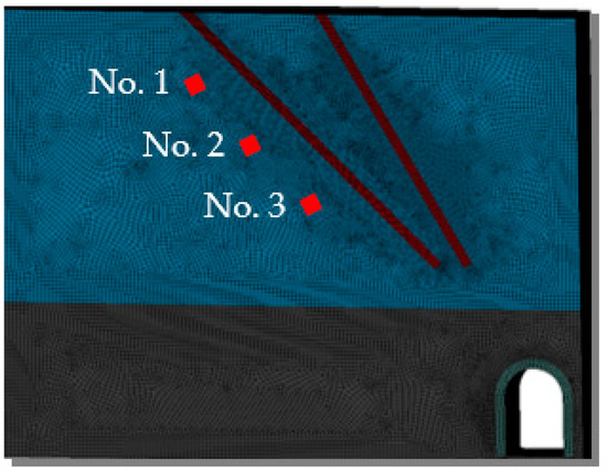
Figure 1.
Three-dimensional numerical model of the deep-hole blasting used in this analysis.
The Jones–Wilkins–Lee equation was used to describe the detonation product expansion process. Thus, the detonation pressure acting on coal and rock at any given time can be expressed as follows:
where P denotes the pressure of the blasting product, MPa; A and B refer to the parameters of explosives, GPa; V annotates the relative volume of detonation products, m3; E0 expresses the internal energy generated by detonation products, GPA; and R1, R2, and ω are characteristic dimensionless explosive parameters [16].
The explosive parameter settings used in the numerical calculations are summarized in Table 1. The mechanical parameters of coal and rock in the numerical model are listed in Table 2.

Table 1.
Parameter setting of explosive in the numerical model.
Table 2.
Numerical simulation parameters of coal and rock.
2.2. Analysis of Results
Effective stress at various times in a cut surface of a blast-hole is depicted in Figure 2. These simulations revealed that blasting stress waves propagated uniformly along the blast-hole at the initial time of development and that stress concentration mainly occurred close to the blast-hole. To analyze the change law of blasting stress in a hard rock body, three stress measurement points at 1, 2, and 3 were set in the numerical model (Figure 1). The effective stress change curve of each measurement point is illustrated in Figure 3.
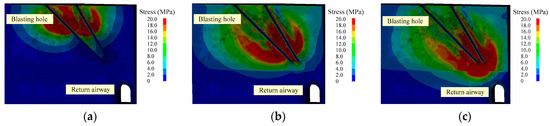
Figure 2.
Partial zoom contours of 3-D effective stress at different times: (a) t = 500 μs, (b) t = 2000 μs, and (c) t = 4500 μs.
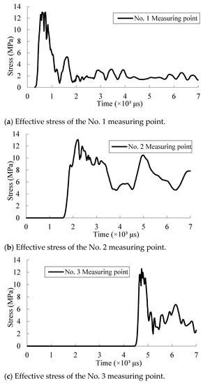
Figure 3.
Effective stress curves of different positions to blast-holes: (a) effective stress of the No. 1 measuring point, (b) effective stress of the No. 2 measuring point, and (c) effective stress of the No. 3 measuring point.
The effective stress reached point 1 at t = 300 μs and then increased swiftly. The maximum effective stress at point 1 was 12.8 MPa. After t = 2000 μs, the stress gradually stabilized. A t = 1600 μs, the maximal effective stress at point 2 was 12.9 MPa. The effective stress reached point 3 at t = 4300 μs. In addition, the maximal effective stress at point 3 was 12.3 MPa. When the blasting stress was greater than the compressive strength of coal and rock, a blasting crushing circle appeared; when the blasting stress was greater than the tensile strength of the coal and rock, a blasting crack occurred. The stress values at the measuring points near the blast-hole were greater than the tensile strength of the rock body, and radial cracks occurred in the rock body.
Figure 4 depicts the extension of the cracks near the blast-holes. Thus, the intensity of the stress wave was far more than the tensile strength of rock because of the combined effect of the detonation wave and quasi-static stress field caused by explosion gas products. Rocks surrounding blast-holes were partially broken, and the cracks in the rocks continuously extended to the bottom, forming crossing fracture networks.
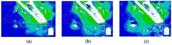
Figure 4.
Development of the crack around the blast-hole: (a) t = 4000 μs, (b) t = 6000 μs, and (c) t = 8000 μs.
To more intuitively observe the crack expansion and development of deep-hole blasting under the condition of a thick and hard roof, a similar simulation test was carried out according to actual coal, and rock conditions were obtained from the II 7224N coal face of the Renlou coal mine.
3. Similar Simulation Test of Deep-Hole Blasting under Thick Sandstone
3.1. Similarity Theory Principle
The simulation test should satisfy geometric similarity, similar motion, similar dynamics, similar boundary conditions, and proportional physical quantities. The model line ratio is expressed as follows:
where xh, yh, and zh denote the geometric dimensions of the prototype along the x, y, and z directions, respectively, and xm, ym, and zm stand for the geometric dimensions of the model along the x, y, and z directions, respectively. The following parameters with subscripts “h” and “m” refer to the parameters on the prototype and model, respectively.
The mode volume–weight ratio is expressed as follows:
The proportional relationship between the material strength and prototype rock strength is expressed as follows:
where and express the strength of model material and prototype rock (tensile or compression), respectively.
If a 100-mm columnar second-level permissible water glue explosive charge is present within a mine, 25 mm is required for this experiment, which is calculated based on the similar relationship between explosion load and charge amount [17]. The experimental cartridge used in the experiment was prepared from a polyvinyl chloride tube. This detonator was applied to detonate the explosive (Figure 5).
Figure 5.
Experimental cartridge production system: (a) experimental detonator and (b) blasting cartridge.
3.2. Experimental Model Construction
The dimensions of the test model were 1.2 × 1 × 1 m3. According to the length similarity ratio in Equation (2), on-site coal and rock of 36 × 30 × 30 m3 can be simulated. The experimental prototype was obtained from the II 7224N coal face of the Renlou coal mine. The measured lithology of the coal face is depicted in Figure 6.
Figure 6.
Histogram of the Ⅱ7224N working face.
The direct roof of the II 7224N coal face was siltstone with an average thickness of 2.88 m, the basic roof was fine sandstone with an average thickness of 13.50 m, the lithologic was hard, and the unidirectional compressive strength was 74.2 MPa. The mechanical parameters of the prototype coal rock are presented in Table 3. The model was simplified during the test process, and the test material proportion parameters are listed in Table 4.
Table 3.
Mechanical parameters of the prototype coal and rock.
Table 4.
Ratio parameters of the materials in blasting tests.
During production of the test model, a special explosive roll was installed at a predesigned position with reference to the numerical simulation model to simulate authentic development of the deep-hole blasting cracks in the thick and hard roof.
3.3. Result Analysis
Crack development in the test model after blasting is illustrated in Figure 7. The rupture cracks extended along the blast-hole to the diagonal of the return airway in the thick hard roof. The damage in the thick roof rock layer was severe. The results of similar simulation experiments verify the fracture development of the numerical model. Broken and fissure areas then formed in the original rock that was not affected by mining, which expanded its original cracks and weak surfaces and weakened the roof, and the development of blasting cracks increased the caving property of the hard and thick roof and the vertical migration channel of gas.
Figure 7.
Crack development of test model after blasting: (a) development of cracks in the blasting model and (b) sketch to show crack development on the surface of the blasting model.
4. Mechanism of Pressure Relief and Permeability Enhancement by Blasting Roof Cutting
4.1. Breaking Laws of the Thick and Hard Roof
The basic top rock layer broke with mining of the coal face. The end of the basic roof produced the phenomenon of rotational subsidence with the coal and rock in front of the coal face as the fulcrum. In addition, the fracture line of the basic roof is the axis under the effect of its own weight and overlying rock layer. The mechanical model is presented in Figure 8, where 1 denotes original stress area, 2 refers to elastic stress area, 3 stands for residual stress area, 4 expresses plastic failure area, εd manifests the ultimate elastic compression of the coal seam, ymax implies ultimate disturbance of basic roof strata, Sb annotates the length of roof subsidence of goaf, L indicates the basic roof length, Lx refers to the periodic pressure step distance of the coal face, Sm denotes the length of subsidence at the end of the basic roof, and Sx stands for the length of subsidence behind the coal face due to basic roof collapse.
Figure 8.
Roof-breaking law of a thick and hard roof.
When the positive moment at the front end of the basic roof block is greater than the reverse moment of the comprehensive mining hydraulic support to the basic roof block, the moment difference in the formation of the basic roof block can be expressed as Equation (5):
where Pre denotes the working load for controlling the movement of the basic top rock block per meter of the support along the coal face, Q annotates the gravity of the basic top rock block per meter along the coal face, Q = Lhγ, h expresses the thickness of basic roof strata, γ refers to the bulk density of the basic top rock layer, and L denotes the length of the basic top rock block. Here, manifests the limiting equilibrium point of the basic roof rock movement governed by the hydraulic support in a fully mechanized coal face. Therefore, we obtain Equation (6):
Thus, we obtain Equation (7):
Thus, the working resistance Pre of hydraulic support in a fully mechanized coal face was related to L, h, and Sm. The longer the basic roof fracture length, the greater the working resistance of the support. If the roof of the fully mechanized coal face is a thick and hard roof, due to its long fracture length, if the roof breaks, the overburden inevitably collapses. Thus, the mechanical balance state of the goaf, hydraulic support, and coal wall was destroyed. In addition, the effect of mine pressure was strong. By reducing the overhang length of the basic roof, the supporting pressure of the roadway can be reduced [18].
4.2. Mechanism of Pressure Relief and Permeability Enhancement
Explosives were blasted in the hard roof rock, which damaged the integrity of the rock. The stress of the rock around the blast-hole shifted away from the damaged rock so that the effective stress on the fully mechanized hydraulic support and the single pillar of the roadway was attenuated. Under the action of the detonation stress wave, plenty of cracks were generated in the rock and the thick and hard roof collapsed as desired in time, which alleviated the range of the suspended ceiling and reduced the roof fracture step distance and the periodic pressure step distance of the coal face. Thus, the additional load on the supports and deformation of the surrounding rock of the roadway were diminished, which protected the roadway [19].
Under the influence of the comprehensive stress field on the coal face, the weak surface of the crack produced by deep-hole blasting and the weak surface of the original crack were connected. The high-level boreholes arranged on the roof use the cracks formed by deep-hole blasting to extract high concentration gas in the deep part of the goaf and to reduce the gas emission from the goaf to the working face to achieve the purpose of proper gas control, as depicted in Figure 9.
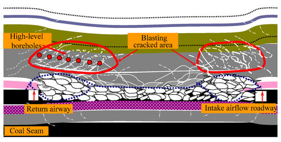
Figure 9.
Schematic diagram on the gas extraction of high-level boreholes in blasting crack.
5. Field Experiment of Pressure Relief and Permeability Enhancement by Blasting Roof Cutting
5.1. Test Face Overview
The II 7224 fully mechanized mining face is the second-level of the Renlou coal mine of Wanbei Coal Power Group Co. (Figure 10). Figure 6 reveals that the roof of the II 7224N fully mechanized coal mining face was a thin direct roof and a thick hard basic roof. The hard roof formed a huge area of overhang without collapsing after coal seam mining. If the roof falls, it can cause severe damage to the roadway. If deformation of the surrounding rock of the roadway is large and the support is seriously damaged, then the stability control of the surrounding rock is disturbed. The average thickness of the 72 coal seam was 2.1 m, and the inclination angle was 17°. The average spacing between the 72 and 73 coal seams was 9 m, and the average spacing between the 73 and 82 coal seams was 11 m.
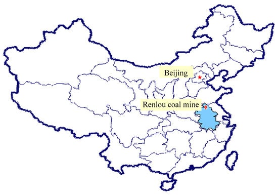
Figure 10.
Renlou coal mine II 7224N coal face (Huaibei, Anhui, PR China).
The gas in the II 7224N fully mechanized coal mining face mainly comes from the coal seam, the adjacent goaf of the II 7222N coal face, and coal seams 73 and 82. High-level gas extraction in the goaf was achieved by drilling holes along the roof. Due to the rigid lithology of the roof, the overhanging area above the goaf was large and developed no cracks. The average gas extraction concentration of high-level gas extraction drilled holes was approximately 10%. The pure extraction volume was 3–4 m3/min. The gas concentration in the upper corner exceeded the limit and reached 5–7% in some places. With the mining of the coal face, the concentration of gas in the upper corner of the coal face continued to increase. However, the problem cannot be solved by using the upper corner buried pipe to extract gas. Therefore, advanced deep-hole blasting was adopted on the II 7224N coal face to weaken the hard roof and to improve the caving properties of the hard and thick roof, and the development of cracks in the roof rock layer was increased. Thus, the maintenance effect of the roadway and the gas drainage efficiency of the borehole were ameliorated.
5.2. Blast-Hole Design and Blasting Process
5.2.1. Blast-Hole Spacing
The blast-hole spacing of advanced deep-hole blasting can be calculated as Equation (8):
where K refers to the adjustment coefficient (generally, it is 10–15), rb expresses the blast-hole radius, and f denotes the rock’s general coefficient. When the hardness of the rock was high, K was smaller; when the hardness was low, it took a larger value [20]. Under this test condition, (m).
5.2.2. Distance of the End of the Blast-Hole
The distance of the end of the blast-hole was determined by factors such as the length of the coal face, the lithologic of the roof, and the occurrence shape of cracks. In general, it was 15–20 m, and the distance of the end of the blasting hole was dictated at 16 m.
5.2.3. Blast-Hole Depth
To ensure that the cross section of the roadway is not affected by blasting, a sufficiently long isolation zone must be left between the hole bottom and the roadway. When one-way drilling is used to arrange the blast-hole, the blast-hole depth is calculated using the following expression:
where S denotes the length of the coal face, s annotates the horizontal distance from the bottom of the hole to the roadway, α expresses the angle between the blast-hole and the roadway, and β stands for the angle between the blast-hole and coal face. The depths of the blast-holes in this study were 20, 28, 39, and 56 m.
5.2.4. Blasting Cycle Step
With continuous mining of the coal face, the periodic pressure step distance of the coal face was approximately 22 m. According to the principle that the blasting cycle steps should not be greater than the basic roof caving step distance and that the blasting quantities should be minimized, each group had four blast-holes. The layout of the blast-hole is displayed in Figure 11, where A1, A2, A3, and A4 are the blast-hole numbers. From the first group to the outside, each group had a 20-m blast-hole interval.
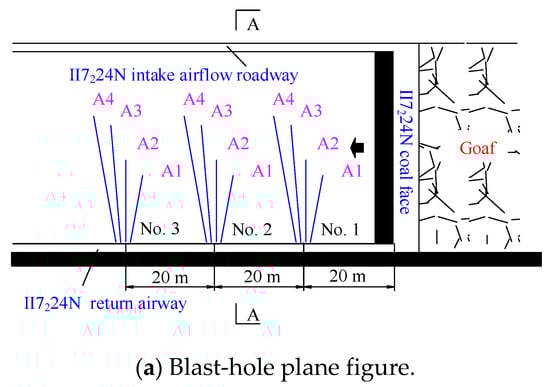
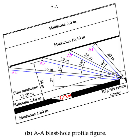
Figure 11.
Deep-hole blasting drilling layout: (a) blast-hole plane figure and (b) A-A blast-hole profile figure.
The parameters of the blast-hole and the charge weight are presented in Table 5. The characteristics of the specially made water glue grains and the continuously charge and blasting explosive parameters are presented in Table 6.
Table 5.
Parameters of blast-hole and charge weight.
Table 6.
Parameters of blasting explosives.
5.3. Pressure Relief Effect after Blasting Roof Cutting
Mining stress in the II 7224N coal face was observed for more than one month. Figure 12 displays the support of working resistance in the coal face after blasting. The observation results revealed that the support working resistance of the struts was extremely unevenly distributed along the direction of the coal face and that the working resistance was relatively low, which was far less than the rated working resistance of the fully mechanized mining hydraulic support in this coal face. The support stiffness ensured the support effect of the coal face and played a pivotal role in ensuring the safety of the coal face.
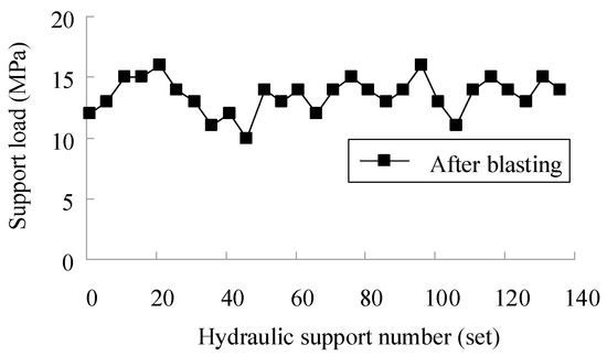
Figure 12.
Support pressure figures after deep-hole blasting.
5.4. Gas Drainage Effect of High-Level Boreholes in the II 7224N Coal Face
After deep-hole blasting, the borehole peep instrument was used to observe the development situation of cracks. The observation results are shown in Figure 13. It truly shows the development pattern of fracture cracks in rock seams after blasting. The rock around the blast-hole generated numerous cracks, it can provide a channel for the vertical migration of gas and can improve the effect of gas extraction.
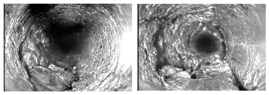
Figure 13.
Development characteristic figures of cracks after deep-hole blasting.
The effectiveness of drilling high-level boreholes for gas control in the coal face depended on the roof of the goaf. The high-level boreholes position of the II 7224N coal face was arranged in the fissure zone, and the distance from the coal seam roof was 11–13 m. To analyze the effect of deep-hole blasting on gas drainage, statistical analyses were conducted on the gas drainage data of high-level gas extraction site 2 before and after blasting. The layout of the high-level boreholes in the gas extraction site is illustrated in Figure 14. Twelve gas extraction boreholes in 2 high-level drill sites are indicated as 1–12.
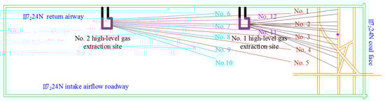
Figure 14.
High-level gas extraction site layout diagram of the II 7224N fully mechanized face.
Figure 15 and Figure 16 indicate that, after deep-hole blasting, the gas drainage quantity of site 2, a high-level gas extraction site, augmented from the original 3–5 to 6–8 m3/min. The extraction concentration was stable at approximately 35%, and the gas concentration at the upper corner of the coal face substantially reduced from 7% to <1%.
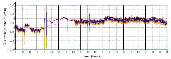
Figure 15.
Curve variation in extraction rate before and after deep-hole blasting.
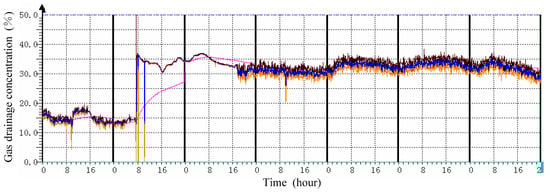
Figure 16.
Curve variation in extraction concentration before and after deep-hole blasting.
6. Conclusions
The results of this study are summarized as follows:
The variation in blasting stress and the distribution of blasting cracks in hard rock were analyzed using numerical analysis and similar simulation experiments. The blasting stress far exceeded the tensile strength of the rock, and the rock around the blast-hole, which was completed in a broken state, generated numerous cracks under the action of the detonation stress wave.
The breaking rules of the hard and thick roof were analyzed, and the mechanism of pressure relief and permeability enhancement by blasting was studied. When the explosive was blasted in the hard rock, the hard and thick roof was destroyed and a vertical gas migration channel was added. Redistribution of stress around the blast-hole prevented violent mine pressure from the excessive fracture distance of the thick and hard roof, reduced the additional load on the support, and thus played a key role in protecting the roadway and in increasing the gas drainage rate of high-level boreholes.
The field application of forced roof cutting by deep-hole blasting in the II 7224N fully mechanized face of the Renlou coal mine revealed that the gas extraction volume of high-level boreholes was maintained at 6–8 m3/min; that the extraction concentration was stable at approximately 35%; and that the gas concentration in the upper corner of the coal face was substantially reduced from 7% to <1%, which ensured normal mining of the coal face.
Author Contributions
Conceptualization, K.G. and J.L.; methodology, Z.-G.L.; validation, F.W.; data curation, K.G.; writing—review and editing, K.G., P.H. and C.-M.S. All authors have read and agreed to the published version of the manuscript.
Funding
This study was financially supported by the National Key R&D Program of China (grant no. 2018YFC0808000), by the National Science Foundation of China (grant nos. 51604010 and 52074013), and by the Natural Science Foundation Project of Anhui Provincial Department of Education (grant nos. KJ2020A0327). These funds are gratefully acknowledged.
Institutional Review Board Statement
Not applicable.
Informed Consent Statement
Not applicable.
Data Availability Statement
The study did not report any data.
Conflicts of Interest
The author confirms that there are no known conflicts of interest associated with this publication and that there has been no significant financial support for this work that could have influenced its outcome.
References
- Wang, C.; Zhao, Y.; Addai, E.K. Investigation on propagation mechanism of large scale mine gas explosions. J. Loss Prev. Process. Ind. 2017, 49, 342–347. [Google Scholar] [CrossRef]
- Fan, J.Y.; Liu, P.; Li, J.J.; Jiang, D.Y. A coupled methane/airflow model for coal gas drainage: Model development and finite-difference solution. Process Saf. Environ. Prot. 2020, 141, 288–304. [Google Scholar] [CrossRef]
- Zheng, C.; Kizil, M.S.; Chen, Z.; Aminossadati, S.M. Role of multi-seam interaction on gas drainage engineering design for mining safety and environmental benefits: Linking coal damage to permeability variation. Process. Saf. Environ. Prot. 2018, 114, 310–322. [Google Scholar] [CrossRef]
- Zheng, C.; Jiang, B.; Xue, S.; Chen, Z.; Li, H. Coalbed methane emissions and drainage methods in underground mining for mining safety and environmental benefits: A review. Process. Saf. Environ. Prot. 2019, 127, 103–124. [Google Scholar] [CrossRef]
- Huo, B.; Jing, X.; Fan, C.; Han, Y. Numerical investigation of flue gas injection enhanced underground coal seam gas drainage. Energy Sci. Eng. 2019, 7, 3204–3219. [Google Scholar] [CrossRef]
- Wang, K.; Du, F. Coal-gas compound dynamic disasters in China: A review. Process. Saf. Environ. Prot. 2020, 133, 1–17. [Google Scholar] [CrossRef]
- Chen, D.; He, W.; Xie, S.; He, F.; Zhang, Q.; Qin, B. Increased permeability and coal and gas outburst prevention using hydraulic flushing technology with cross-seam borehole. J. Nat. Gas Sci. Eng. 2020, 73, 103067. [Google Scholar] [CrossRef]
- Wei, P.; Huang, C.; Li, X.; Peng, S.; Lu, Y. Numerical simulation of boreholes for gas extraction and effective range of gas extraction in soft coal seams. Energy Sci. Eng. 2019, 7, 1632–1648. [Google Scholar] [CrossRef]
- Gao, K.; Liu, Z.G.; Liu, J.; Deng, D.S.; Gao, X.Y.; Kang, Y.; Huang, K.F. Study on application of deep borehole blasting to gob-side entry retaining forced roof caving in hard and compound roof deep well. Chin. J. Rock Mech. Eng. 2013, 32, 1588–1594. [Google Scholar]
- Wang, F.; Tu, S.; Yuan, Y.; Feng, Y.; Chen, F.; Tu, H. Deep-hole pre-split blasting mechanism and its application for controlled roof caving in shallow depth seams. Int. J. Rock Mech. Min. Sci. 2013, 64, 112–121. [Google Scholar] [CrossRef]
- Gong, M.; Zhang, F.G.; Wen, B.; Wang, H. Numerical simulation and application on blasting to improve gas drainage rate in floor rock of coal roadway. J. China Coal Soc. 2012, 37, 972–977. [Google Scholar]
- Liu, J.; Liu, Z.G.; Gao, K.; Jiang, E.L. Application of deep borehole blasting to top-coal pre-weakening and gas extraction in fully mechanized caving. Chin. J. Rock Mech. Eng. 2014, 33, 3361–3367. [Google Scholar]
- Wang, H.B.; Xu, X.; Zong, Q.; Xu, S.M.; Xu, Y. Research and application of hard rock deep-hole advance blasting in comprehensive roadway excavation. J. China Coal Soc. 2017, 42, 908–915. [Google Scholar]
- He, M.C.; Gao, Y.B.; Yang, J.; Guo, Z.B.; Wang, E.Y.; Wang, Y.J. An energy-gathered roof cutting technique in no-pillar mining and its impact on stress variation in surrounding rocks. Chin. J. Rock Mech. Eng. 2017, 36, 1314–1325. [Google Scholar]
- Yuan, C.F.; Yuan, Y.; Zhu, C.; Meng, C.G. Reasonable parameters of roof cutting entry retaining in thin immediate roof and large mining height fully-mechanized face. J. China Coal Soc. 2019, 44, 1981–1990. [Google Scholar]
- Livermore Software Technology Corporation. LS-DYNA Keyword User’s Manual; LS-DYNA R11 [R]; Livermore Software Technology Corporation: Livermore, CA, USA, 2018. [Google Scholar]
- Mu, C.M.; Qi, J. Model investigation on cracks propagation in coal under blast loading. J. Vib. Shock 2012, 31, 58–61. [Google Scholar]
- Qian, M.G.; Miao, X.X.; Xu, J.L. Theoretical study of key strata in ground control. J. China Coal Soc. 1996, 21, 225–230. [Google Scholar]
- Gao, Y.; Wang, Y.; Yang, J.; Zhang, X.; He, M. Meso- and macroeffects of roof split blasting on the stability of gateroad surroundings in an innovative nonpillar mining method. Tunn. Undergr. Space Technol. 2019, 90, 99–118. [Google Scholar] [CrossRef]
- Ma, X.; He, M.; Wang, J.; Gao, Y.; Zhu, D.; Liu, Y. Mine Strata Pressure Characteristics and Mechanisms in Gob-Side Entry Retention by Roof Cutting under Medium-Thick Coal Seam and Compound Roof Conditions. Energies 2018, 11, 2539. [Google Scholar] [CrossRef]


Publisher’s Note: MDPI stays neutral with regard to jurisdictional claims in published maps and institutional affiliations. |
© 2021 by the authors. Licensee MDPI, Basel, Switzerland. This article is an open access article distributed under the terms and conditions of the Creative Commons Attribution (CC BY) license (https://creativecommons.org/licenses/by/4.0/).