Article

Simulation of Glass Fiber Reinforced Polypropylene Nanocomposites for Small Wind Turbine Blades

1
Department of Mechanical Power Engineering, Faculty of Engineering, Port Said University, Port Said 42526, Egypt
2
Faculty of Applied Engineering, Muzahimiyah Branch, King Saud University, Riyadh 11451, Saudi Arabia
3
Department of Chemical Engineering, Faculty of Engineering, Port Said University, Port Said 42526, Egypt
4
Materials Science Program, University of Science and Technology, Zewail City of Science and Technology, October Gardens, 6th of October 12578, Egypt
*
Author to whom correspondence should be addressed.
Processes 2021, 9(4), 622; https://doi.org/10.3390/pr9040622
Submission received: 19 January 2021 / Revised: 28 March 2021 / Accepted: 31 March 2021 / Published: 1 April 2021

Abstract

:
This study aims to evaluate the effect of functionalized multi-walled carbon nanotubes (MWCNTs) on the performance of glass fiber (GF)-reinforced polypropylene (PP) for wind turbine blades. Support for theoretical blade movement of horizontal axis wind turbines (HAWTs), simulation, and analysis were performed with the Ansys computer package to gain insight into the durability of polypropylene-chopped E-glass for application in turbine blades under aerodynamic, gravitational, and centrifugal loads. Typically, polymer nanocomposites are used for small-scale wind turbine systems, such as for residential applications. Mechanical and physical properties of material composites including tensile and melt flow indices were determined. Surface morphology of polypropylene-chopped E-glass fiber and functionalized MWCNTs nanocomposites showed good distribution of dispersed phase. The effect of fiber loading on the mechanical properties of the PP nanocomposites was investigated in order to obtain the optimum composite composition and processing conditions for manufacturing wind turbine blades. The results show that adding MWCNTs to glass fiber-reinforced PP composites has a substantial influence on deflection reduction and adding them to chopped-polypropylene E-glass has a significant effect on reducing the bias estimated by finite element analysis.

1. Introduction

Carbon dioxide and other greenhouse gases that contribute to global warming are not released by renewable energy sources such as sun and wind [1]. In the power field, composites are of benefit in the wind sector, especially in manufacturing of turbine blades and the use of the finite element method. Finite element analysis is a feasible tool for simulating/predicting how wind, heat, and solar radiation, centrifugal force, and gravitational loading will affect the blades and the ideal geometry for turbine optimization [2,3,4,5]. A wind turbine blade with a class 1 kW horizontal axis was constructed and investigated by Park [6]. The wind turbine blade was fabricated using a natural flax fiber composite. The design outcomes of areas of the flax/epoxy composite blade were compared with the layout outcomes of glass/epoxy composite blade. To calculate the structural design of the composite blade, a static finite element analysis was performed. Structural analysis confirms that structural protection, blade tip deflection, structural integrity, resonance, and weight are suitable for the engineered natural fiber reinforced polymer composites.
A selection process for an airfoil and the aerodynamic design of a rotor blade were addressed by Habali and Saleh [7]. To build the rotor blade, they used glass fiber reinforced plastic (GFRP) and performed a static resistance test to evaluate its load-bearing potential. Sharma and Shukla [8] studied the impact of carbon nanotubes dispersion and functionalization on the relevant properties of multigrade carbon epoxy composites. With the addition of carbon nanotubes (CNTs) in plastic, Young’s modulus, interlayer shear strength, and flexural modulus improved by 51.46, 39.62, and 38.04%, respectively.
Using finite element analysis, the structural response of a small composite wind turbine blade subjected to gyroscopic load was studied by Costa et al. [9]. As a case study, a 5 kW small wind turbine blade was used for aerogenesis. A finite element model of the 2.5 m long composite blade was constructed, and the accuracy of its forecasts against experimental data was verified. The predicted results indicated that gyroscopic loading caused the blade to deflect in any direction of the fin and forward sheet, resulting in relatively excessive stresses within the structure of the composite blade.
Ullah et al. [10] used a comprehensive finite element modeling to simulate structural integrity and failure in composite blades using Ansys software. The outcomes confirmed that the blade was subjected to high compressive force, causing local displacement of the skin. In addition, the analysis outcomes indicated skin–spar debonding due to warping on the adhesive surface. This is the preliminary failure mode that can lead to gradual deterioration of the blade structure.
In terms of the mechanical properties of polymer composites, fibers play a crucial role. They have qualities that are reinforcing [11,12,13]. In each case, however, there are certain properties to be considered. Glass fibers (GFs), carbon fibers (CFs), and aramid fibers (AFs) are the most widely used in the production of wind turbine blades [14,15,16,17,18,19]. Other examples are nylon, polyester (PE), polytetrafluoroethylene (PTFE), jute, flax, and steel fibers, which are used for specific purposes [4].
In contrast to carbon fibers, glass fibers have a less complex modulus and are usually less costly. They have the advantage of being electrically non-conductive and hence the metallic-based construction frame of the turbine blades, will not produce a galvanic cell over time. In the fiber phase in the matrix, diverse characteristics include combinations of different materials will be durable and able to withstand a range of influences the blade material is exposed to.
In contrast to thermoset matrices, composites with thermoplastic matrices show greater resistance to impact loads [20]. Thermoplastic composites exhibit ductile modes of failure rather than brittle failure [21]. Unlike ruptures in thermosets, thermoplastic composites undergo plastic deformation [22]. The strength of composites strengthened by glass fibers depends on the interface between the glass fibers and the polymers. Due to their high specific strength, impact resistance, infinite shelf life, high strain before failure, and short processing time, glass fiber-reinforced thermoplastic composites are used in many applications [23]. The physical and chemical properties depend upon the composition. High compatibility makes GF material effective. The compatibility of GF with polymer matrices can be increased by modifying the glass fiber surface or introducing additives in a polymer matrix. However, application of this method is highly cost-dependent. E-glass fibers are preferred in the plastic industry, as they are cheaper than available grades of GFs [24].
With the application of heat, thermoplastics flow readily [25,26,27]. They are perfect for manufacturing by extrusion or molding injection. It is a complex art to impregnate thermoplastics with fibers. The term “semipreg” is used to explain how thermoplastics are impregnated with fibers. This is because rather than impregnating, the resin acts more like a coating.
Carbon nanotubes can be used to enhance the mechanical properties of wind blades. However, when processing composites, CNTs tend to aggregate in bundles. The main properties of CNTs are high modulus, on the order of 100 GPa; high tensile strength of approximately 50,000 MPa; and density of 1.33 g/cm3. Other properties include high electrical conductivity, thermal conductivity, and insensitivity to thermal degradation [28].
Many factors are involved in the extrusion process to keep reinforcement undamaged, e.g., the loading of reinforcing fibers, the dimensions of the extruder with respect to the barrel, and the heating and opening of the die. High barrel pressure can reduce the tensile strength; however, the orientation of fibers improve with higher injection speed, and thus improve the mechanical properties [29,30,31,32]. In injection molding, fiber orientation is crucial, as shear forces are present. Usually, orientation is ignored hence strength gained in one direction is not attainable in another direction. Short-chopped fiber, particle whiskers, and particles are common reinforcement tools used in injection molding. In general, the length of reinforcement is not greater than the size of mold gate. The typical length of fibers used in injection molding can be up to 25.4 mm. Fiber length is an important factor in the mechanical properties of a part obtained from injection molding. The average length of short fibers is 0.33 mm, whereas long fibers average 2.9 mm. The higher aspect ratio of long fibers provides superior mechanical properties compared to short fibers [20].
In a study done by Crowson et al. [33], neat polypropylene (PP) was compared with 20 wt.% glass fiber-filled PP. Entrance pressure drop was found to increase six times in the presence of glass fibers [34]. During injection molding processing, fibers are subjected to high stresses in the viscous melt. This causes them to break and deform. By studying fiber behavior under different flow conditions, adjustments can be made to maintain a high aspect ratio. This will enhance the reinforcing capacity of fibers. There is a direct relation between the loading level of glass fiber and the mechanical properties of GF/PP composite. In one study, PP was loaded by 10, 20, 28, and 35 wt.% glass fiber in an injection molding process. It was found that a higher percentage of glass fiber loading resulted in lower reinforcement efficiency [35].
During polymer melting, fiber is subjected to high shear and bending forces. This makes the bending load more than the failure load, and breakage occurs. Once the critical stress value is reached, the glass fibers break, and natural fibers break by repeated deformation cycles. Initially, reprocessing leads to increased fiber dispersal within the matrix, but repeated reprocessing will cause a loss of mechanical properties.
Excessive reprocessing causes mechanical as well as thermal degradation of matrix and reinforcement. The matrix is degraded by random chain scissions in the polymer chain, which is likely to decrease the molecular weight of the polymer and cause a loss in mechanical properties. In a study on the effect of molecular weight on interfacial properties of GF/PP composites, it was found that recycled PP with lower molecular weight has low viscosity that enables it to penetrate easily. This leads to higher interfacial strength between GF and PP, resulting in more breakage of GF during tensile tests [36].
In this work, PP was chosen as the thermoplastic matrix material for a small wind turbine blade used in residential applications because (i) it is relatively cheap, (ii) readily available, and (iii) commercial PP blades are available for comparative analysis using Ansys software. Fabrication of wind turbine rotor blades with thermoplastics is rarely covered in the literature, but some examples are available. In this research, multi-walled carbon nanotubes (MWCNTs) are mixed with polypropylene composite to improve the mechanical properties. Moreover, an intensive study was conducted on the interfacial force between PP and glass fiber in the presence of functionalized MWCNTs. This study is aimed at evaluating the suitability of glass fiber (GF)-reinforced polypropylene (PP) composites for wind turbine blades. The rotor blade length is in the range of 0.5 to 1.3 m, typically used for small-scale wind turbine systems such as for residential applications. To our knowledge, most researchers have studied fiber-reinforced thermoset (epoxy and vinyl ester) nanocomposites for wind turbine blade fabrication, and no detailed study has been conducted on glass fiber-reinforced thermoplastic-functionalized nanocomposites for blade manufacture. Desirable properties of functional CNTs, including excellent electrical, thermal conductivity, and mechanical properties, will help in enhancing the performance of thermoplastic composites for wind blade applications.

2. Materials and Methods

Glass fiber-reinforced polypropylene samples were fabricated in the presence of MWCNTs. Different chopped glass fiber and MWCNT loadings were applied and tested.

2.1. Material Characterization

2.1.1. Glass Fiber

Glass fiber properties are provided according to the technical data sheet from the supplier as listed in Table 1.

2.1.2. Multi-Walled Carbon Nanotubes (MWCNTs)

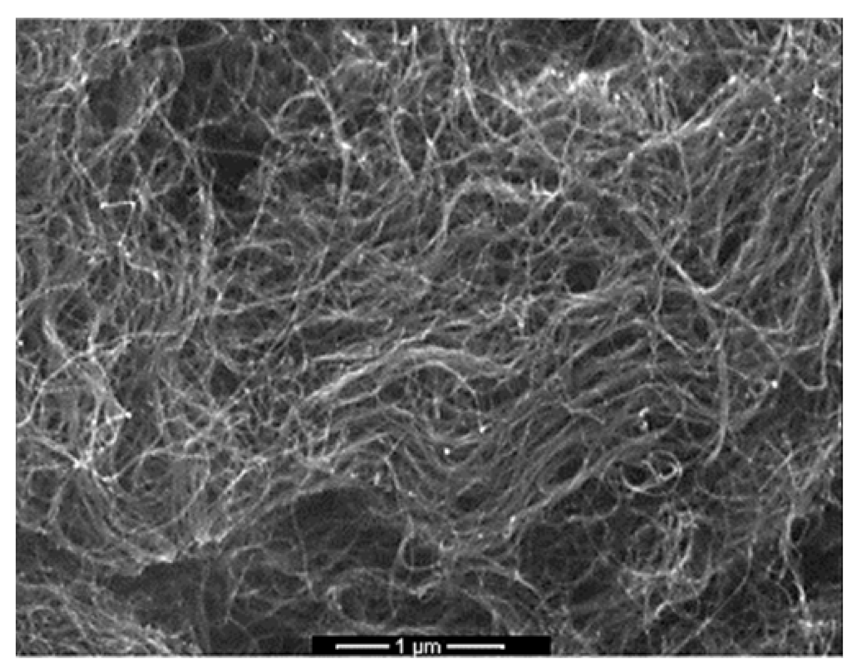
The MWCNTs were received from Grafen (Ankara, Turkey). Surface morphology and manufacturer’s specifications are listed in Table 2. It is found that the aspect ratio (ratio of length to diameter) of MWCNTs is 170. The catalytic chemical vapor deposition technique was used to produce CNTs. This process gives more than 90% carbon nanotubes and less than 10% metal oxides [37].

2.1.3. Synthesis of Glass Fiber-Reinforced Polypropylene-Carbon Nanotube Composites

Molding grade polypropylene (PP) was selected as the matrix material. For excellent mold filling, good shine, high stiffness, and antistatic properties, a homopolymer (density 0.9 g/cm3) was applied. E-glass (UK) chopped strand with an alkali content of less than 1% and polyvinyl acetate coated with a silane binding agent was used. The density of the glass fiber was 2.56 g/cm3, the mean length of the fiber was 2.5 mm, and the diameter was 10 µm, with an aspect ratio of 250.
Glass fiber-reinforced PP MWCNT composites were synthesized and manufactured using extrusion and injection molding processes. The weight percentages of MWCNTs varied between 0 and 8 wt./wt.%. Physical and mechanical properties were measured using tensile tests. The effect of MWCNTs on the melt flow index (MFI) and mechanical properties of PP-GF composites was studied. The fracture surface of PP composites was examined using SEM analysis.

2.1.4. PP-Nanocomposite Processing

Glass fiber (~10 wt.%) was mixed in a co-rotating twin extruder at 200 °C and 270 rpm with PP-MWCNTs as a master batch (1–15%) and pristine PP. The composite was then shredded and processed at 200 °C and 500 bar using injection molding (Allrounder, Arburg, Germany) to produce tensile and sheet sample shapes. Specimens for determination of tensile properties according to ISO 527-4 189 (multidirectional and fiber-reinforced materials) were fabricated as rectangles with dimensions of 25 mm width, 250 mm length, and 3 mm thickness. A tensile evaluation was carried out using a Zwick B066550 universal testing machine (Germany). A 10 kN load cell was employed. The rate of tension at room temperature was 2 mm/s. To investigate the effect of MWCNTs on the PP flow property, the melt flow index was determined.

2.2. Model Wind Turbine

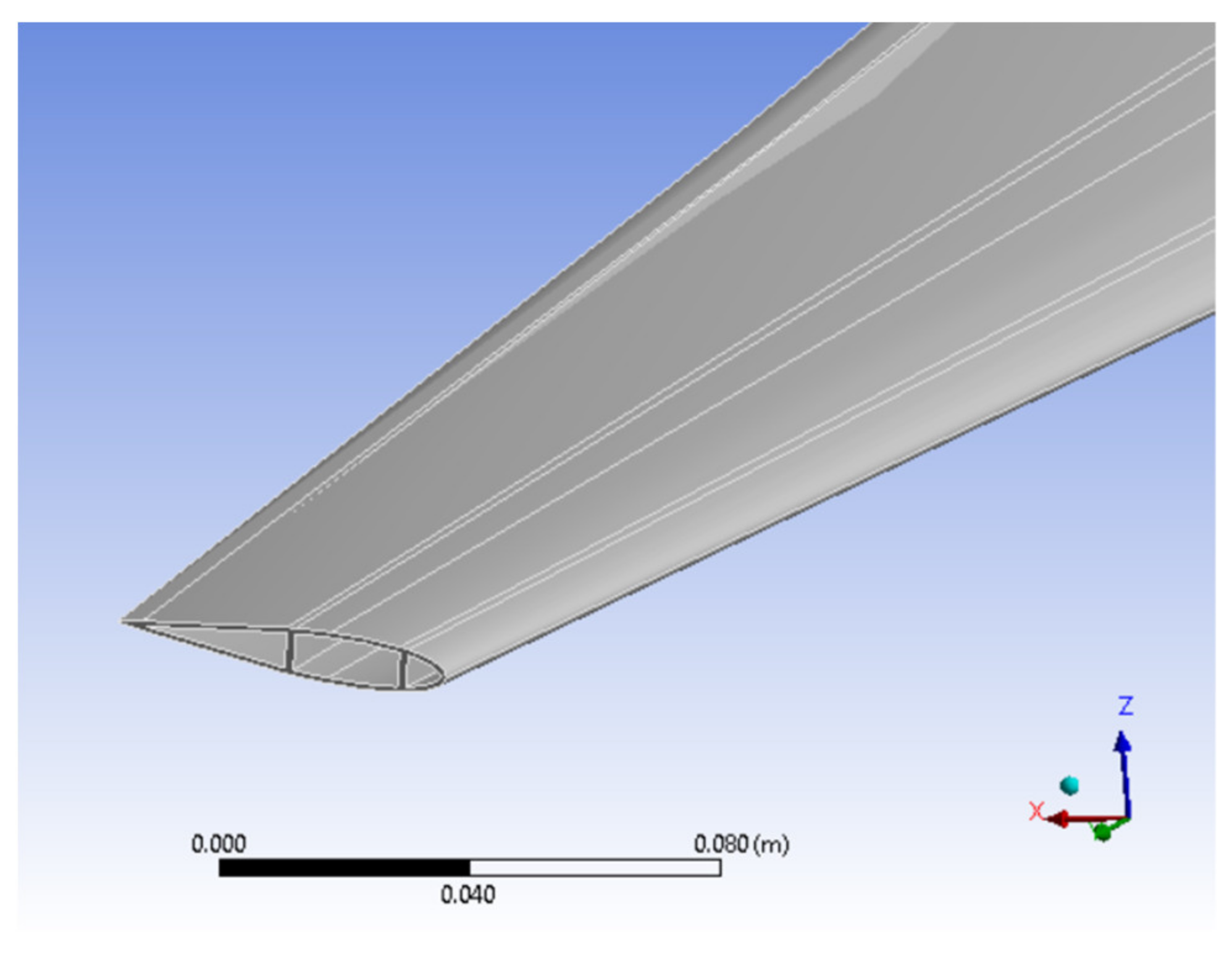
Based on an optimization analysis, the HAWT geometry and its operating conditions were chosen. More information on optimizing wind turbine performance is given below. The HAWT variable is a three-bladed HAWT with a diameter of 1.26 to 2.83 m. Each blade followed the profile of the NACA20015 airfoil and had a blade length between 0.5 and 1.3 m. This gave an aspect ratio of 3, 4, 5, 6, or 7 based on the ratio between the diameter of the turbine and the length of the blade. The turbine rotates at 34.26 rad/s under optimum conditions when the wind speed is 7 m/s. Table 3 shows the key parameters of the optimized turbine. The 3D geometry and main dimensions of the optimized HAWT are shown in Figure 1. The shape of the blade cross-section, comprising two shear webs, is shown in Figure 2.
The tip speed ratio (TSR), which determines the relative wind speed and the blade velocity, is shown in Equation (1):
TSR = ω R C w
where ω is rotor speed (rad/s), R is radius (m), and C w is wind speed (m/s).

3. Results and Discussion

3.1. Tensile Properties of GF-PP-MWCNT Composites

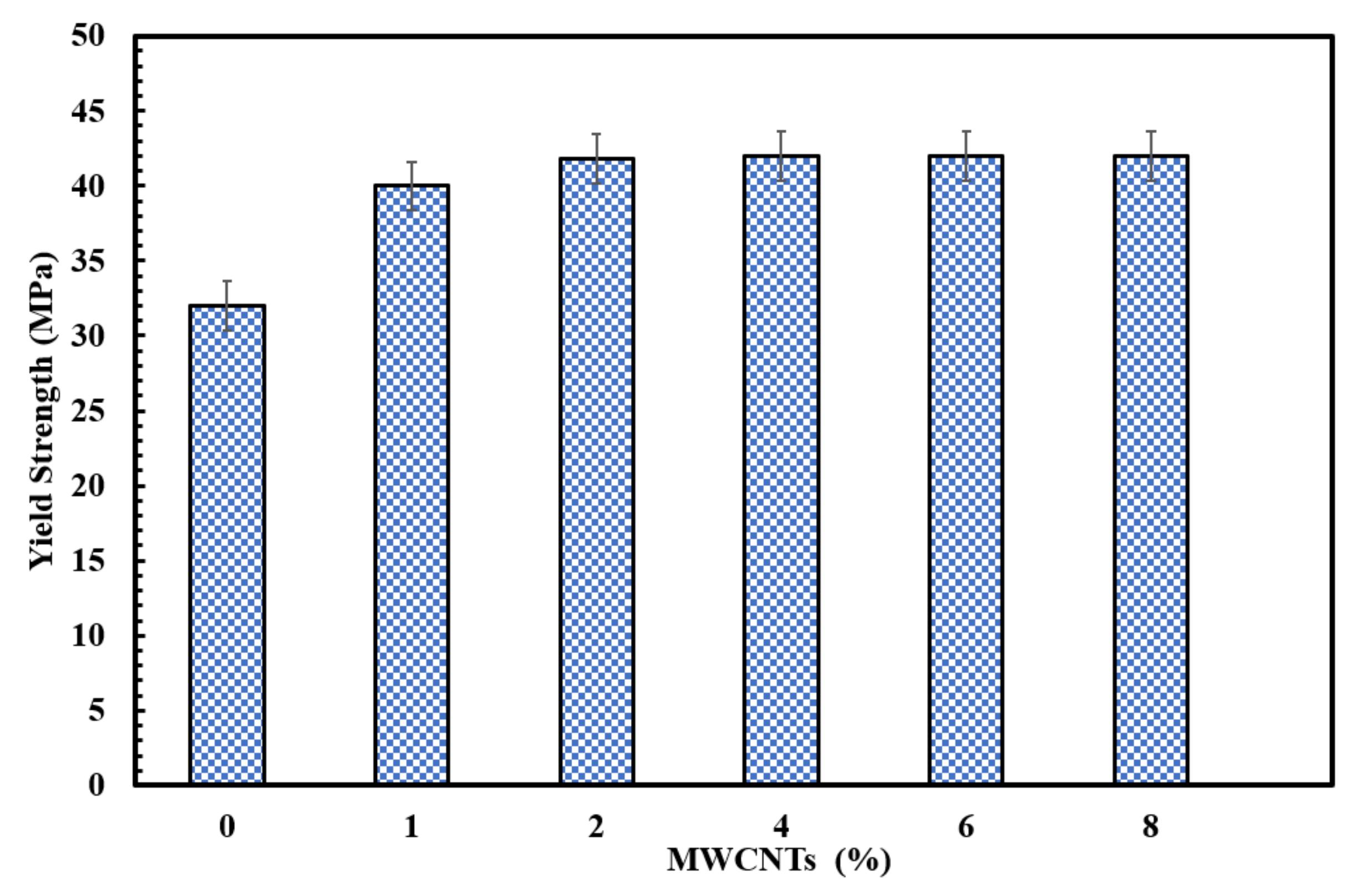
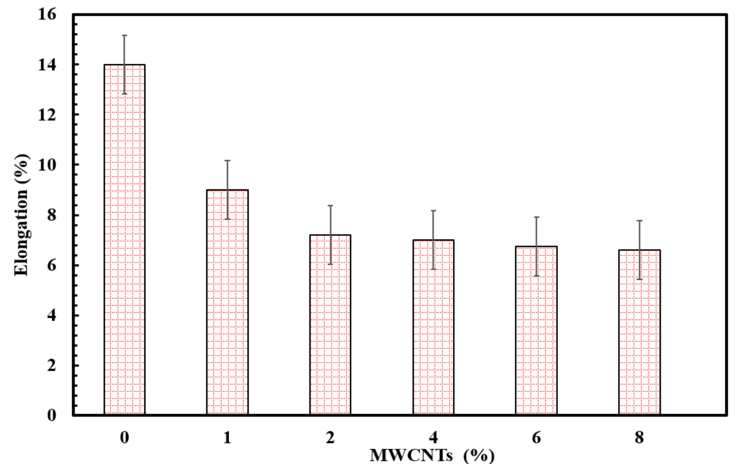
The glass fiber-reinforced PP-MWCNT system showed superior strength compared to PP/GF composites. A substantial improvement (up to 36%) in the strength of GF-reinforced PP was obtained in the presence of MWCNTs (2% wt./wt.) compared to neat polypropylene (31 MPa). At higher CNT loading, the yield strength of GF-PP nanocomposites did not show remarkable improvement, as shown in Figure 3. This can be attributed to the high affinity of CNTs as they create tiny clusters/agglomerates and impact the composite structure. The modulus of elasticity of PP-MWCNTs improved remarkably from 1.5 to 2.5 GPa in the presence of MWCNTs (2% wt./wt), as observed in Figure 4. The loading of MWCNTs showed significant improvement in modulus of elasticity behavior from 1 to 8% wt./wt. It was shown that stiffness did not primarily depend on the filler–matrix interface, but more on the absolute filler content in the direction of tensile loading, as the elastic modulus is determined at low strain values (0.05–0.25%) as a tangent modulus, where no interfacial de-bonding is considered to occur even in the event of weak adhesion [20]. Therefore, the expected enhancement of the bonding of fillers/matrix does not affect the composite stiffness/modulus of elasticity. Around 49% reduction in elongation in the presence of 2% wt./wt. of MWCNTs was recorded, as shown in Figure 5.

3.2. Melt Flow Index of PP-Chopped E-Glass Fiber Composites

Since the PP composites were manufactured using injection molding, the melt flow index (MFI) has a significant influence on their quality. The melt flow index is a single point measurement that gives an indication of the ability of the polymer to flow. To this end, MFI was measured according to ISO 1133 at a temperature of 230 °C and a weight of 2.16 kg. The average of 10 MFI values was considered.
The MFI of PP-MWCNT composites decreased with increased MWCNT %, as shown in Table 4. Higher-density PP composites are obtained as MWCNTs are added. The MFI of the neat PP is around 11 g/10 min. The PP-MWCNT composite samples had much lower MFI values than the neat PP at higher concentrations. Higher MFI correlates with lower viscosity at that fixed shear rate.
Results are in agreement with previous studies that showed lower MFI in the presence of fillers [38].

3.3. Surface Analysis of PP-Glass Fiber Composites

Figure 6 shows the direction and length of the glass fibers using digital microscopy (Keyence VHX-500F, Osaka, Japan). When fiber length is greater than critical length, the tension is expected to rise linearly. It is observed that the average fiber length was reduced to 0.63 mm due to extrusion and injection processes. If the fiber length is less than the critical length, fiber pull-out or matrix–fiber interfacial bond failure can occur. It was reported that PP-glass fiber composite stiffness reached the maximum value with a fiber length of 1 mm [39].

3.4. Surface Morphology

It is possible to visually detect the presence of interfacial adhesion due to chemical coupling. The fracture surface can be investigated by scanning electron microscopy (SEM). Surface morphology analysis can discriminate between uncoupled and chemically bound composites. If the fiber surface is smooth, this means the surface did not adhere to the matrix. There is also confirmation at the base of the glass fiber that de-bonding has taken place.
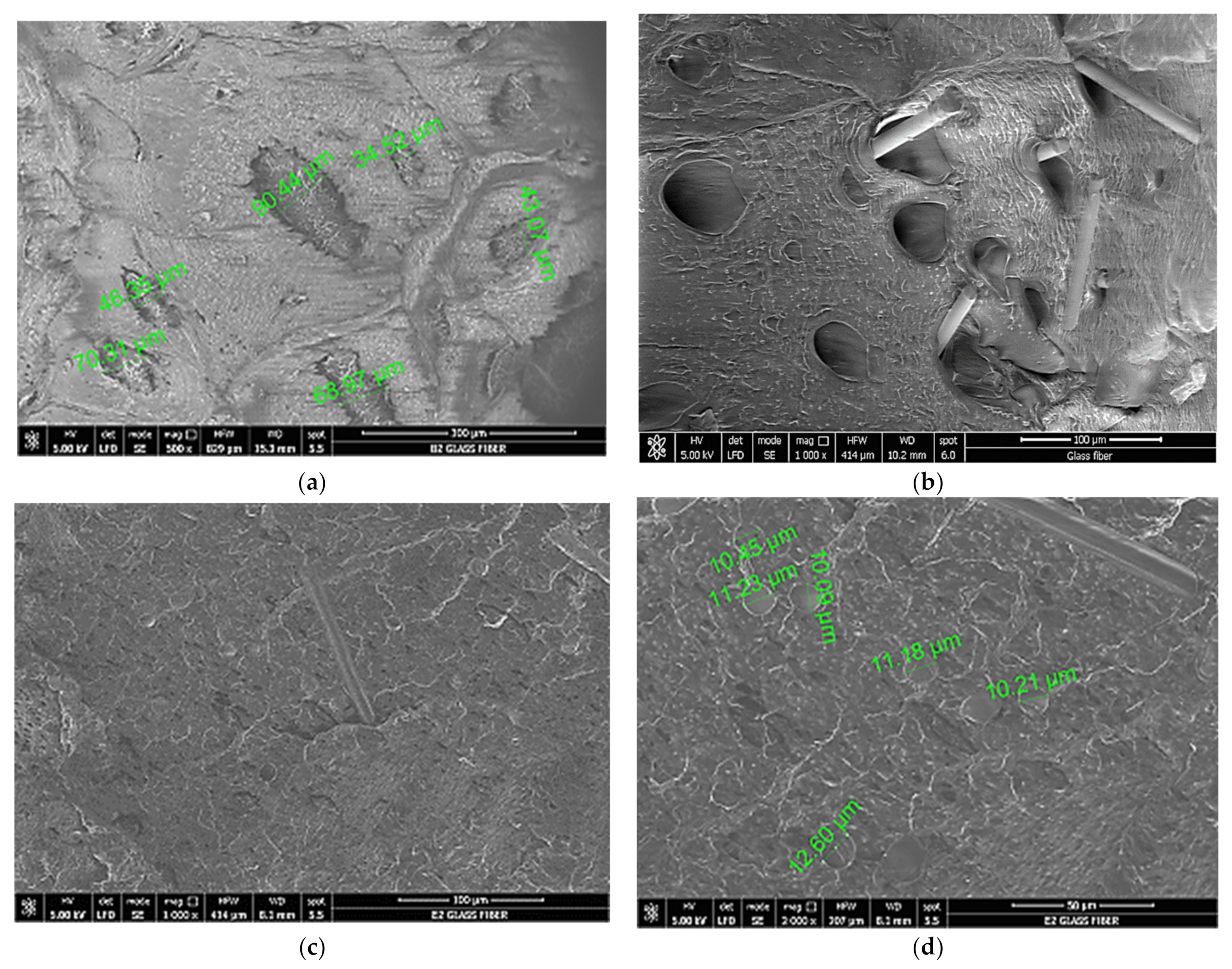
The tensile fracture morphology of the PP–glass fiber interface was studied using SEM at different chopped glass fiber and MWCNTs loadings (Figure 7). In the case of PP-GF (Figure 7a,b), many cavities were observed. Some glass chopped fibers were observed where the fiber pulled out. This indicates poor interfacial bonding between the matrix and the dispersing phase. As the glass fiber content increases, the poor interfacial bonding and the brittleness of the filler affect the tensile property (increasing the modulus). However, the mechanical properties are significantly modified in the presence of modified MWCNTs. Figure 7c,d shows fewer pores at the fracture surface, good glass fiber dispersibility, and matrix layers covering the fiber surface, which reflects good adhesion between polypropylene, glass fiber, and MWCNTs.

3.5. Finite Element Method Modelling

The finite element method (FEM) simulation of the optimized HAWT with composite blades was carried out using the Ansys Static Structural module, a widely used FEA modeling program. To optimize the HAWT geometry, the FEM modeling procedure was applied. A comprehensive overview of the geometry, meshing, materials, and boundary conditions in the FEM model are included in this section.

3.5.1. Geometry

A shaft and three blades form the geometry of the built HAWT as stipulated. The geometry in the SolidWorks software is generated. Figure 8 shows the shape of the HAWT geometry. Table 5 lists the properties of the thermoplastic (PP) and two different composites formulated based on it the FEM mode of the proposed HAWT.

3.5.2. FEA Mesh

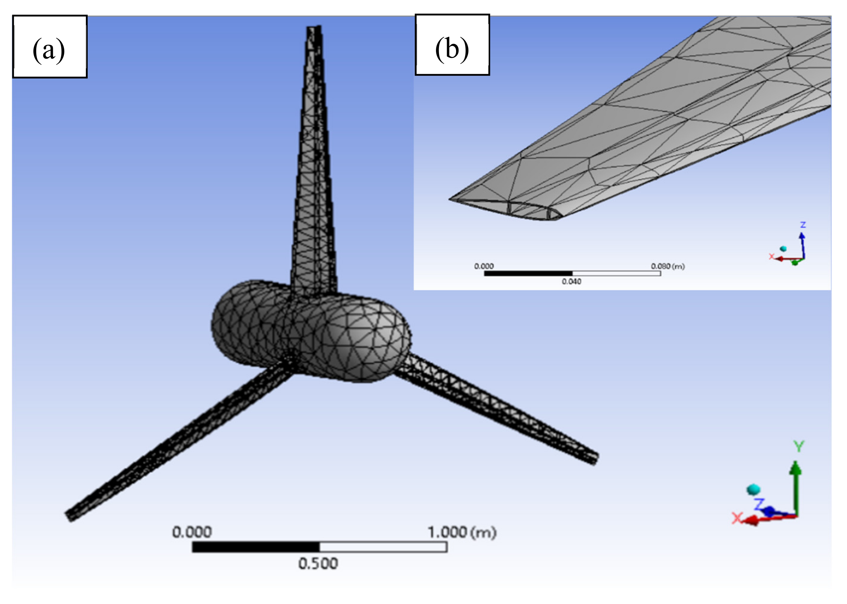
For meshing of the HAWT, the standardized mesh topology was used. The baseline mesh for the entire turbine is shown in Figure 8a, and the standardized mesh for the turbine blade is shown in Figure 8b. In order to select a suitable mesh that would provide good accuracy and have a fair computing cost, a mesh sensitivity analysis was carried out. Three meshes were developed for this analysis: coarse mesh with 33,489 nodes, baseline mesh with 96,700 nodes, and fine mesh with 137,467 nodes. Further details are available in Table 6. Figure 9 shows the effect of mesh size using PP/GF material at the expected maximum deflection for the highest rotational velocity of 26.22 rad/s. It is noted that the baseline and fine mesh predictions were in strong agreement, while in the coarse mesh it is significantly underestimated. The baseline mesh with 96,700 nodes and 20,100 elements was therefore considered to be the appropriate mesh and was used for further research.

3.5.3. Boundary Conditions

Horizontal axis wind turbines (HAWTs) are subjected to several loads, including aerodynamic, gravitational, and centrifugal loads. The current research focuses primarily on the effects of the various structural materials on the blade deflection at different centrifugal loads. Centrifugal loads correspond to the tip speed ratio (TSR). By applying the relevant rotational velocity, these centrifugal loads are applied to the HAWT rotor in the Ansys Static Structural program.

3.5.4. Solution and Post-Process Results

For the solution and post-processing of observations, the Ansys Static Structural program was used. This software, including static and modal analysis, is capable of numerous structural analyses. Several findings, such as blade deformation and stress distribution, can be derived. In the present analysis, the blade deformation is derived from simulations of the static structure.
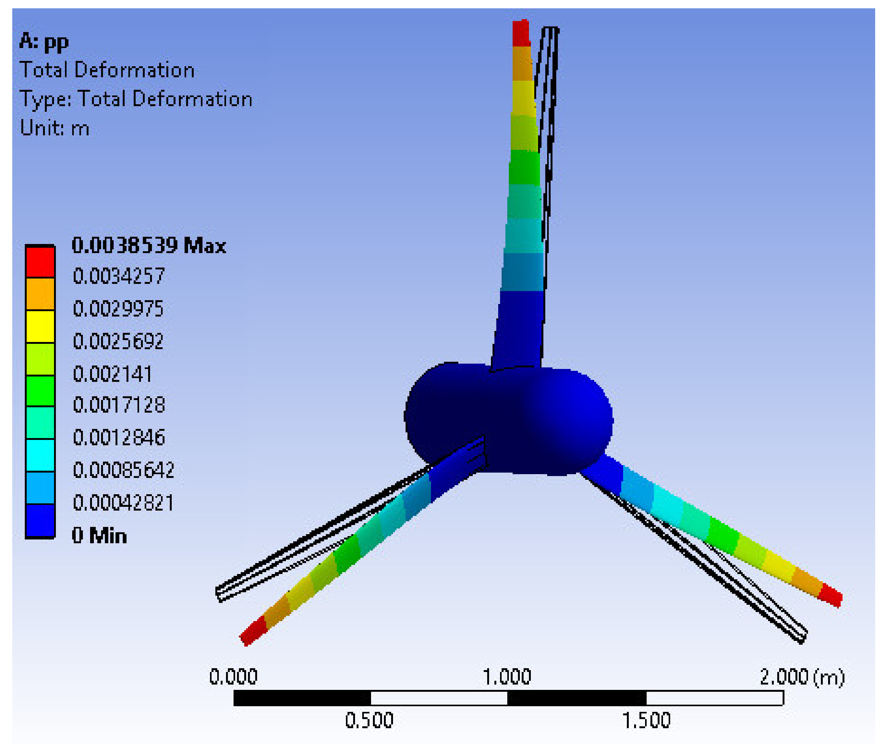
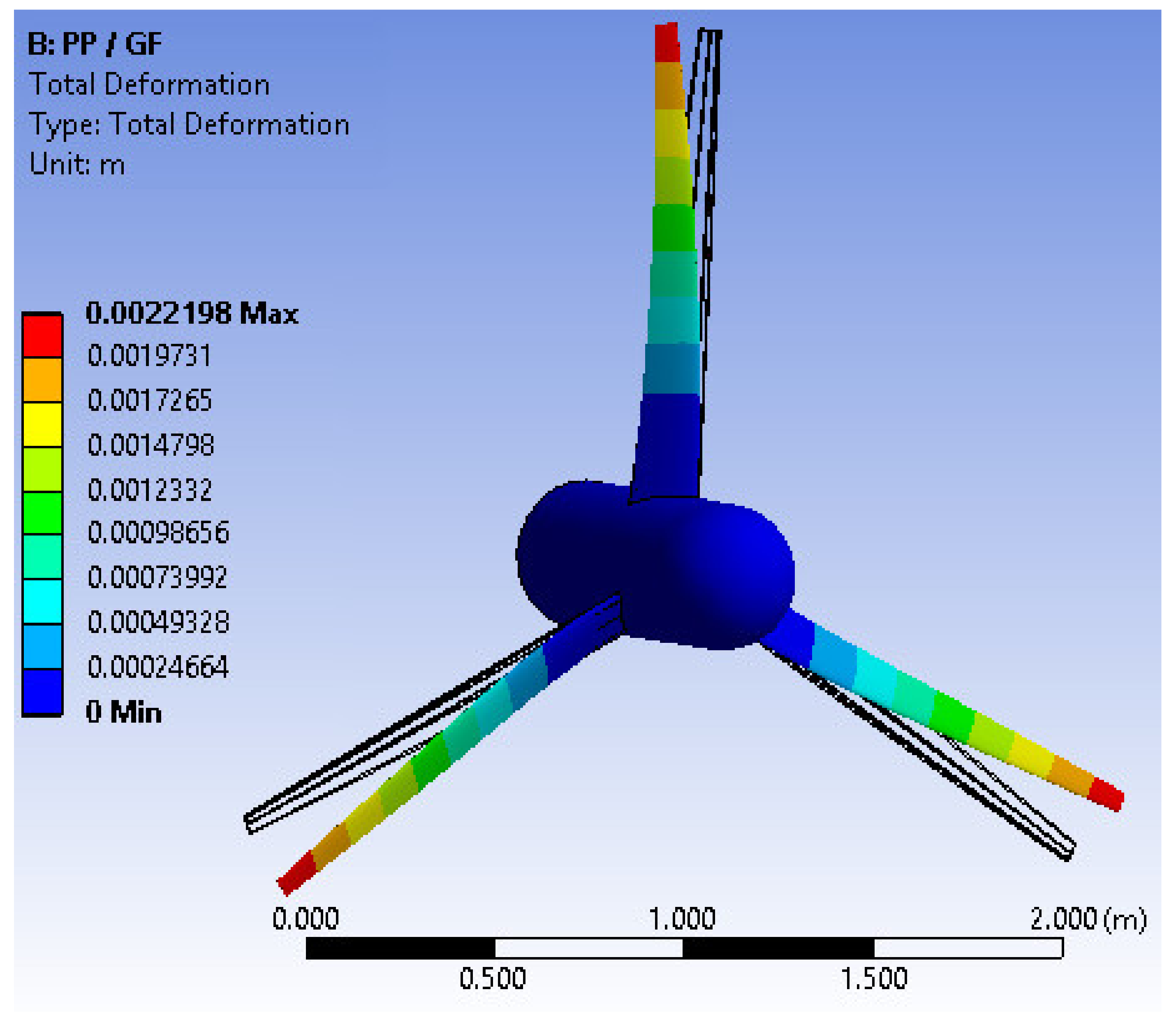
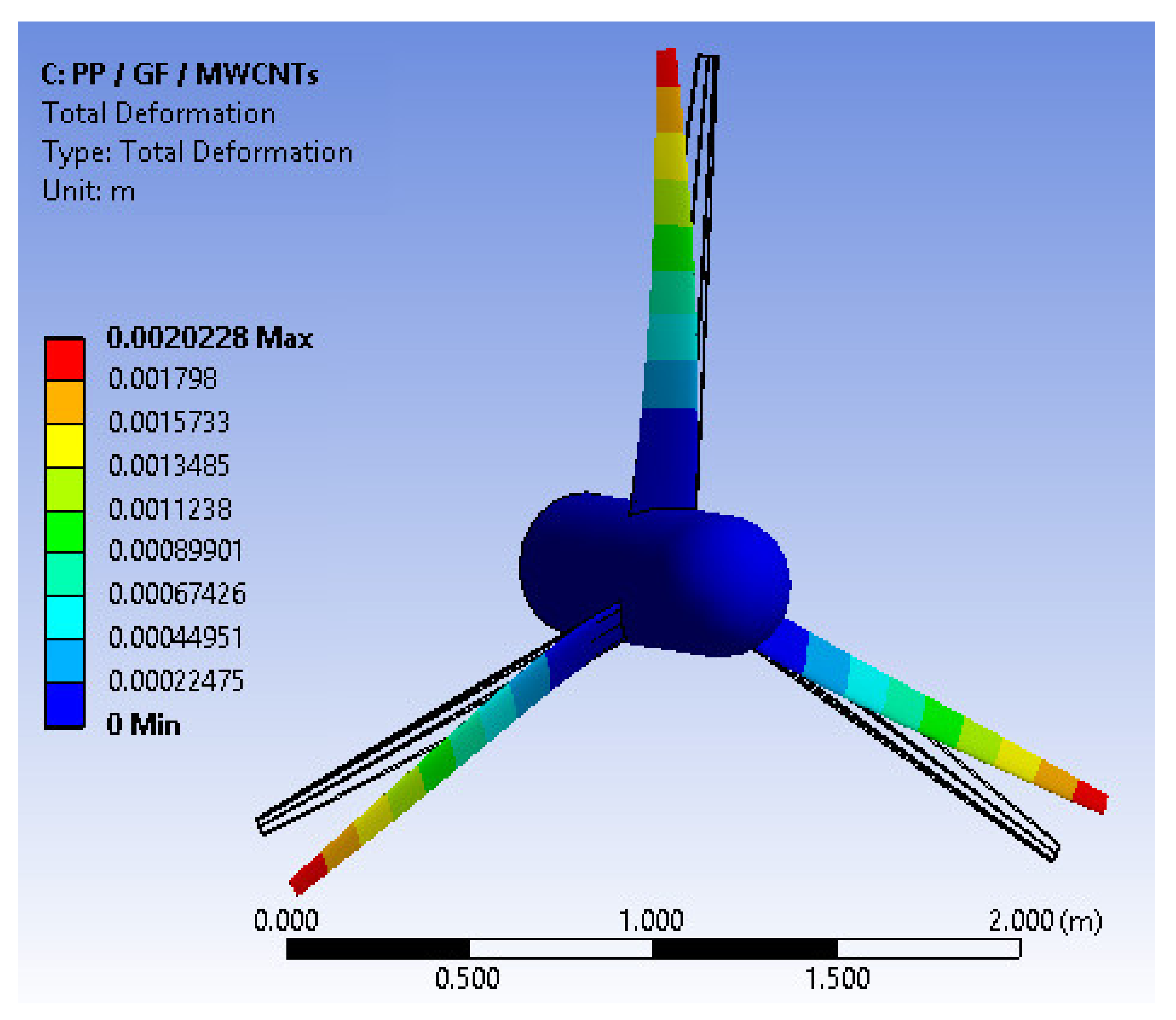
The FEM structure analysis of an optimized HAWT was performed based on the method described in Section 2. Graphical representations of the deformation of turbine blades made with PP, glass fiber-reinforced PP, and glass fiber-reinforced PP-MWCNT materials are shown in Figure 10, Figure 11 and Figure 12, respectively, at an ideal TSR of 3. It was noted that maximum deflections occurred at the blade ends, while strong deflections were observed at the blade midspan. In order to study the impact of applying different materials to maximum deflection at different centrifugal loads, various experiments were carried out. The maximum deflection of the blades at TSR of 7 for different materials is shown in Figure 13.
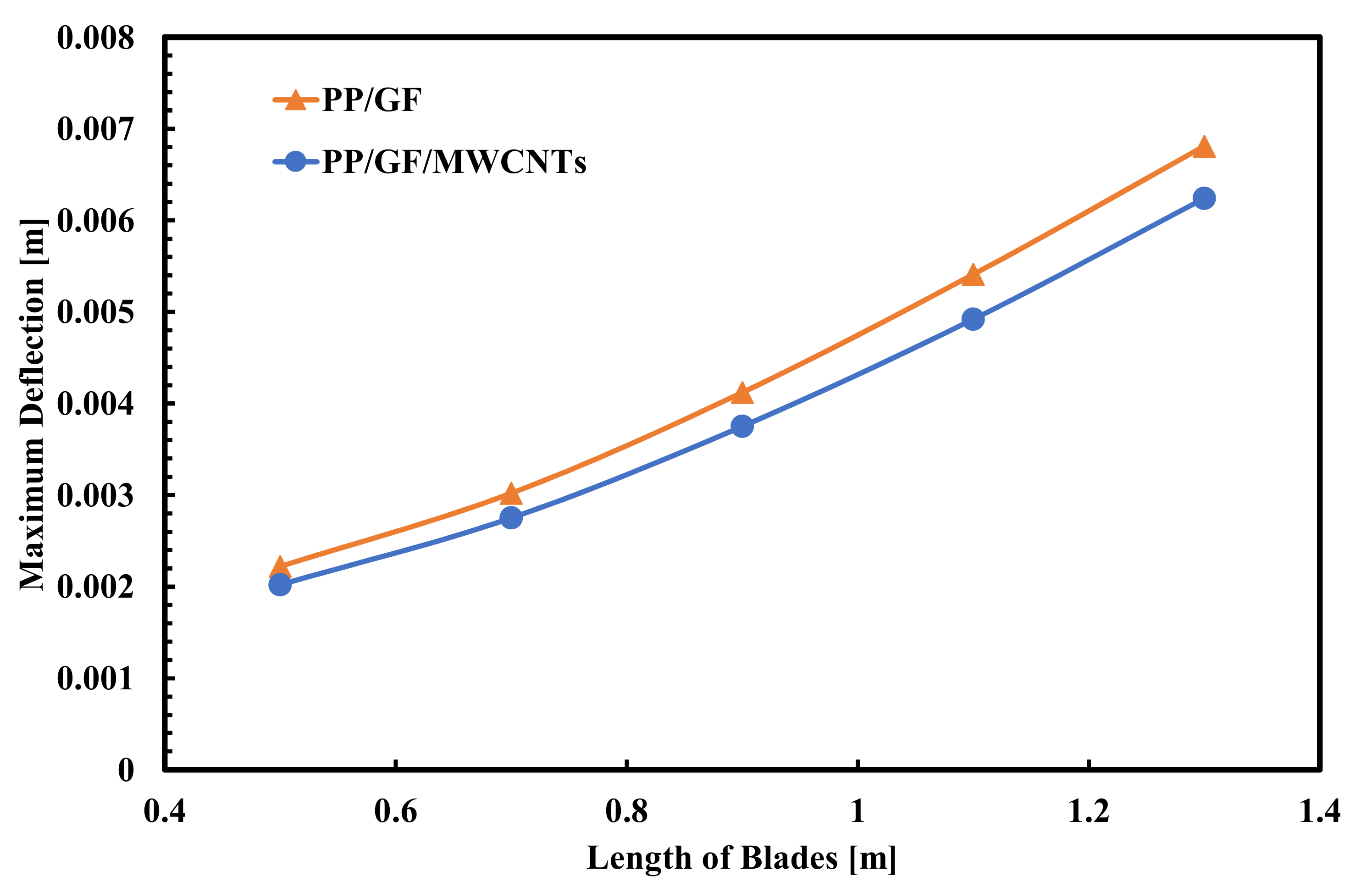
Figure 14 shows the maximum deflections found using the Ansys Static Structural program. It can be seen that adding MWCNTs of 2% to glass fiber-reinforced PP composite material leads a reduction in deflection by 10% compared with GF-reinforced PP.

4. Conclusions

Glass fiber-reinforced polypropylene nanocomposites were fabricated using the injection molding process. Addition of 2 wt./wt.% MWCNTs and 10 wt./wt.% GF to polypropylene yielded remarkable improvement in the tensile strength of polypropylene. Ansys analysis showed enhancement of blade deflection using MWCNTs in wind blades of different lengths. Compared with GF-reinforced PP, the addition of 2 wt./wt.% MWCNTs to glass fiber-reinforced PP composite material contributed to a 10% reduction in deflection. It is found that short glass fiber-reinforced PP nanocomposites can be effectively used to fabricate small/micro wind turbine blades. For larger wind blades, GF-reinforced PP nanocomposites can be used with continuous glass fiber to synthesize hybrid materials with superior mechanical properties.

Author Contributions

Conceptualization, Y.F. and Y.E.; methodology, Y.F.; software, Y.E.; validation, H.M., M.B. and Y.F.; formal analysis, Y.F.; investigation, Y.F. and M.B.; resources, Y.F. and H.M.; data curation, M.B.; writing—original draft preparation, Y.F.; writing—review and editing, M.B.; visualization, Y.E.; supervision, M.B.; project administration, Y.F.; funding acquisition, Y.F. All authors have read and agreed to the published version of the manuscript.

Funding

The authors extend their appreciation to the Deputyship for Research & Innovation, Ministry of Education in Saudi Arabia for funding this research work through the project number (DRI-KSU-1410).

Institutional Review Board Statement

Not applicable.

Informed Consent Statement

Not applicable.

Data Availability Statement

The data presented in this study are available on request from the corresponding author.

Conflicts of Interest

The authors declare no conflict of interest.

References

  1. Zoromba, M.S.; Tashkandi, M.; Alshehri, A.; Abdel-Aziz, M.; Bassyouni, M.; Mahmoud, S.; Ben Slimane, A.; Al-Hossainy, A. Polymer solar cell based on doped o-anthranilic acid and o-aminophenol copolymer. Opt. Mater. 2020, 104, 109947. [Google Scholar] [CrossRef]
  2. Ashby, M.; Bréchet, Y.; Cebon, D.; Salvo, L. Selection strategies for materials and processes. Mater. Des. 2004, 25, 51–67. [Google Scholar] [CrossRef]
  3. Elhenawy, Y.; Hafez, G.; Abdel-Hamid, S.; Elbany, M. Prediction and assessment of automated lifting system per-formance for multi-storey parking lots powered by solar energy. J. Clean. Prod. 2020, 266, 121859. [Google Scholar] [CrossRef]
  4. Marsh, G. Reinforced plastics transform ‘small wind’ market. Reinf. Plast. 2004, 48, 22–26. [Google Scholar] [CrossRef]
  5. Bassyouni, M.; Gutub, S. Materials selection strategy and surface treatment of polymer composites for wind turbine baldes fabrication. Polym. Polym. Compos. 2013, 21, 463–471. [Google Scholar]
  6. Park, H. A study on structural design and analysis of small wind turbine blade with natural fibre (flax) composite. Adv. Compos. Mater. 2015, 25, 1–18. [Google Scholar] [CrossRef]
  7. Habali, S.; Saleh, I. Local design, testing and manufacturing of small mixed airfoil wind turbine blades of glass fibre reinforced plastics: Part I: Design of the blade and root. Energy Convers. Manag. 2000, 41, 249–280. [Google Scholar] [CrossRef]
  8. Sharma, K.; Shukla, M. Three-phase carbon fiber amine functionalized carbon nanotubes epoxy composite: Pro-cessing, characterisation, and multiscale modeling. J. Nanomater. 2014, 2014. [Google Scholar] [CrossRef]
  9. Da Costa, M.S.P.; Clausen, P.D. Structural Analysis of a Small Wind Turbine Blade Subjected to Gyro-scopic Load. J. Phys. Conf. Ser. 2020, 1618, 042006. [Google Scholar] [CrossRef]
  10. Ullah, H.; Ullah, B.; Silberschmidt, V.V. Structural integrity analysis and damage assessment of a long composite wind turbine blade under extreme loading. Compos. Struct. 2020, 246, 112426. [Google Scholar] [CrossRef]
  11. Junaedi, H.; Baig, M.; Dawood, A.; Albahkali, E.; Almajid, A. Mechanical and Physical Properties of Short Carbon Fiber and Nanofiller-Reinforced Polypropylene Hybrid Nanocomposites. Polymers 2020, 12, 2851. [Google Scholar] [CrossRef] [PubMed]
  12. Fanaradelli, T.D.; Rousakis, T.C. 3D Finite Element Pseudodynamic Analysis of Deficient RC Rectan-gular Columns Confined with Fiber Reinforced Polymers under Axial Compression. Polymers 2020, 12, 2546. [Google Scholar] [CrossRef] [PubMed]
  13. Sherif, G.; Chukov, D.I.; Tcherdyntsev, V.V.; Torokhov, V.G.; Zherebtsov, D.D. Effect of Glass Fi-bers Thermal Treatment on the Mechanical and Thermal Behavior of Polysulfone Based Composites. Polymers 2020, 12, 902. [Google Scholar] [CrossRef] [PubMed] [Green Version]
  14. Sommer, V.; Stockschläder, J.; Walther, G. Estimation of glass and carbon fiber reinforced plastic waste from end-of-life rotor blades of wind power plants within the European Union. Waste Manag. 2020, 115, 83–94. [Google Scholar] [CrossRef] [PubMed]
  15. Joustra, J.; Flipsen, B.; Balkenende, R. Structural reuse of high end composite products: A design case study on wind turbine blades. Resour. Conserv. Recycl. 2021, 167, 105393. [Google Scholar] [CrossRef]
  16. Boyano, A.; Lopez-Guede, J.; Torre-Tojal, L.; Fernandez-Gamiz, U.; Zulueta, E.; Mujika, F. Delamination Fracture Behavior of Unidirectional Carbon Reinforced Composites Applied to Wind Turbine Blades. Materials 2021, 14, 593. [Google Scholar] [CrossRef]
  17. Rizk, P.; Al Saleh, N.; Younes, R.; Ilinca, A.; Khoder, J. Hyperspectral imaging applied for the detection of wind turbine blade damage and icing. Remote. Sens. Appl. Soc. Environ. 2020, 18, 100291. [Google Scholar] [CrossRef]
  18. Elhenawy, Y.; Fouad, Y.; Marouani, H.; Bassyouni, M. Performance Analysis of Reinforced Epoxy Functionalized Carbon Nanotubes Composites for Vertical Axis Wind Turbine Blade. Polymers 2021, 13, 422. [Google Scholar] [CrossRef]
  19. Rodrigues, S.; Marta, A. On addressing wind turbine noise with after-market shape blade add-ons. Renew. Energy 2019, 140, 602–614. [Google Scholar] [CrossRef]
  20. Bassyouni, M.; Taha, I.; Abdel-Hamid, S.M.-S.; Steuernagel, L. Physico-mechanical properties of chemically treated polypropylene rice straw bio-composites. J. Reinf. Plast. Compos. 2012, 31, 303–312. [Google Scholar] [CrossRef] [Green Version]
  21. Bassyouni, M.; Sherif, S.A.; Sadek, M.; Ashour, F. Synthesis and characterization of polyurethane–Treated waste milled light bulbs composites. Compos. Part B Eng. 2012, 43, 1439–1444. [Google Scholar] [CrossRef]
  22. Cosco, F.; Serratore, G.; Gagliardi, F.; Filice, L.; Mundo, D. Experimental Characteri-zation of the Torsional Damping in CFRP Disks by Impact Hammer Modal Testing. Polymers 2020, 12, 493. [Google Scholar] [CrossRef] [PubMed] [Green Version]
  23. Feih, S.; Wei, J.; Kingshott, P.; Sørensen, B.F. The influence of fibre sizing on the strength and fracture toughness of glass fibre composites. Compos. Part A Appl. Sci. Manuf. 2005, 36, 245–255. [Google Scholar] [CrossRef]
  24. Thomason, J.; Jenkins, P.; Yang, L. Glass Fibre Strength—A Review with Relation to Composite Recycling. Fibers 2016, 4, 18. [Google Scholar] [CrossRef]
  25. Rehman, S. Wind energy resources assessment for Yanbo, Saudi Arabia. Energy Convers. Manag. 2004, 45, 2019–2032. [Google Scholar] [CrossRef]
  26. Biron, M. Future Prospects for Thermoplastics and Thermoplastic Composites Technical Information for Plastic Users; Elsevier: Oxford, UK, 2007. [Google Scholar]
  27. Chandler, H. Wind Energy, the Facts an Analysis of Wind Energy in the EU-25; European Wind Energy Association: Brussels, Belgium, 2007. [Google Scholar]
  28. Theodore, M.; Hosur, M.; Thomas, J.; Jeelani, S. Influence of functionalization on properties of MWCNT–epoxy nanocomposites. Mater. Sci. Eng. A 2011, 528, 1192–1200. [Google Scholar] [CrossRef]
  29. Sathishkumar, T.P.; Satheeshkumar, S.; Naveen, J. Glass fiber-reinforced polymer composites–A review. J. Reinf. Plast. Compos. 2014, 33, 1258–1275. [Google Scholar] [CrossRef]
  30. Jarukumjorn, K.; Suppakarn, N. Effect of glass fiber hybridization on properties of sisal fiber–polypropylene composites. Compos. Part B Eng. 2009, 40, 623–627. [Google Scholar] [CrossRef]
  31. Arbelaiz, A.; Fernández, B.; Cantero, G.; Llano-Ponte, R.; Valea, A.; Mondragon, I. Mechanical properties of flax fibre/polypropylene composites. Influence of fibre/matrix modification and glass fibre hybridization. Compos. Part A Appl. Sci. Manuf. 2005, 36, 1637–1644. [Google Scholar] [CrossRef]
  32. Huda, M.S.; Drzal, L.T.; Mohanty, A.K.; Misra, M. Chopped glass and recycled newspaper as reinforcement fibers in injection molded poly(lactic acid) (PLA) composites: A comparative study. Compos. Sci. Technol. 2006, 66, 1813–1824. [Google Scholar] [CrossRef]
  33. Wharton, S.; Lundquis, J. Atmospheric stability affects wind turbine power collection. Environmental Res. Lett. 2012, 7, 1–9. [Google Scholar] [CrossRef]
  34. Crowson, R.; Folkes, M.; Bright, P. Rheology of short glass fibre-reinforced thermoplastics and its application to injec-tion moulding I. Fibre motion and viscosity measurement. Polym. Eng. Sci. 2004, 20, 925–933. [Google Scholar] [CrossRef]
  35. Thomason, J. The influence of fibre length and concentration on the properties of glass fibre reinforced polypropylene. 6. The properties of injection moulded long fibre PP at high fibre content. Compos. Part A Appl. Sci. Manuf. 2005, 36, 995–1003. [Google Scholar] [CrossRef] [Green Version]
  36. Kam, T.; Jiang, J.; Yang, H.; Chang, R.; Lai, F.; Tseng, Y. Fabrication and Testing of Composite Sandwich Blades for a Small Wind Power System. In Proceedings of the PEA-AIT International Conference on Energy and Sustainable Development: Issues and Strategies. Asian Institute of Technology, Klong Luang, Thailand, 2–4 June 2010. [Google Scholar]
  37. Wang, X.-D.; Vinodgopal, K.; Dai, G.-P. Synthesis of Carbon Nanotubes by Catalytic Chemical Vapor Deposition. Perspect. Carbon Nanotub. 2019. [Google Scholar] [CrossRef] [Green Version]
  38. Nurul, M.; Mariatti, M. Effect of thermal conductive fillers on the properties of polypropylene composites. J. Thermoplast. Compos. Mater. 2011, 26, 627–639. [Google Scholar] [CrossRef]
  39. Thomason, J. The influence of fibre length and concentration on the properties of glass fibre reinforced polypropylene: 5. Injection moulded long and short fibre PP. Compos. Part A Appl. Sci. Manuf. 2002, 33, 1641–1652. [Google Scholar] [CrossRef]
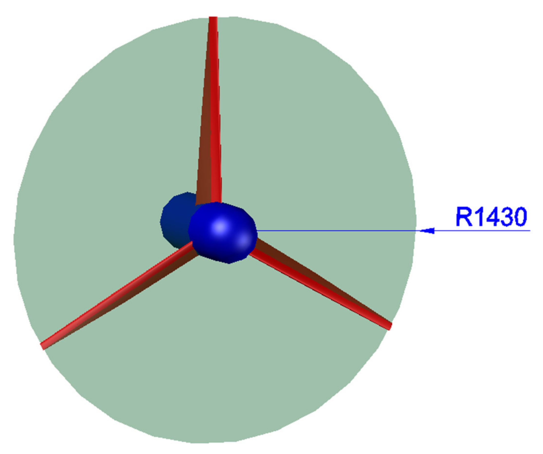
Figure 1. 3D model of geometry of optimized HAWT.
Processes 09 00622 g001
Figure 2. 3D model of geometry of optimized HAWT blade.
Processes 09 00622 g002
Figure 3. Effect of MWCNTs on the yield strength of PP-GF composites.
Processes 09 00622 g003
Figure 4. Effect of MWCNTs on modulus of elasticity of PP-GF composites.
Processes 09 00622 g004
Figure 5. Effect of MWCNTs on elongation of PP-GF nanocomposites.
Processes 09 00622 g005
Figure 6. Glass fiber length and distribution in GF-PP composites using 3-D surface images.
Processes 09 00622 g006
Figure 7. SEM PP composites: (a) cavities, (b) glass fiber surface, (c) PP-GF- modified MWCNTs, (d) fiber distribution in PP GF–modified MWCNTs.
Processes 09 00622 g007
Figure 8. Finite element analysis of mesh: (a) blade; (b) close view of blade tip.
Processes 09 00622 g008
Figure 9. Effect of mesh size using PP/GF material on expected maximum deflection for highest rotational velocity of 26.22 rad/s.
Processes 09 00622 g009
Figure 10. Graphical representation of maximum turbine blade deformation with PP material at TSR = 3.
Processes 09 00622 g010
Figure 11. Graphical representation of maximum turbine blade deformation with PP/GF material at TSR = 3.
Processes 09 00622 g011
Figure 12. Graphical representation of maximum turbine blade deformation with PP/GF/MWCNT content at TSR = 3.
Processes 09 00622 g012
Figure 13. Maximum deflection of blades with various materials at TSR = 7.
Processes 09 00622 g013
Figure 14. Maximum deflection of different blade material.
Processes 09 00622 g014
Table 1. Physical and mechanical properties of glass fiber.
ParameterValue
Tensile strength at break (MPa)Warp: 1555; weft: 1387
Moisture content0.11%
Density (kg/m3)2.55 × 103
Thermal conductivity (W/m °C)1.3
Electrical resistivity (Ω⋅m)1.0 × 10¹⁴
Length (mm)2.5
Diameter (µm)13
Density (kg/m3)2600
Coupling agentPolyvinyl acetate with silane
Table 2. Specifications of multi-walled carbon nanotubes (MWCNTs).
Multi-Walled Carbon NanotubesSEM _MWCNTs
Surface area275 m2/g Processes 09 00622 i001
Carbon purity> 90%
Diameter~10 nm
Length~1.7 μm
Metal oxides9%
Table 3. Main parameters of optimized horizontal axis wind turbine (HAWT).
ParametersValuesUnit
No. of blades3
Radius of rotor (R)r + Lm
Radius of hub (r)0.13m
Length of blade (L)0.5, 0.7, 0.9, 1.1, 1.3m
Rated speed of wind ( C w )7m/s
Rated speed of the rotor ( ω )34.26rad/s
AirfoilNACA0015
Table 4. Effect of MWCNTs on melt flow index (MFI) of polypropylene.
MWCNTs wt.%012468
MFI11.08.46.203.300.470.03
Table 5. Various properties of glass fiber-reinforced thermoplastic composites.
PropertyPPPP/GF (Short Fiber Composite) at 10% wt./wt.PP/GF/MWCNTs
Density (kg/m3)90010201030
Thermal expansion coefficient (µstrain/°C)27.110.49.7
Thermal conductivity (Wm−1k−1)0.880.2670.307
Specific heat capacity (JKg−1k−1)193216501700
Tensile strength (MPa)3234.542
Poisson’s ratio0.430.320.30
Young’s modulus (GPa)1.341.722.5
Table 6. Information on various meshes used in mesh sensitivity analysis.
Coarse MeshBaseline MeshFine Mesh
Nodes33,48996,700137,467
Elements721020,10027,523
Maximum deflection (mm)3.6526.3226.721
Publisher’s Note: MDPI stays neutral with regard to jurisdictional claims in published maps and institutional affiliations.