Article

Flow Characteristics and Energy Loss within the Static Impeller of Multiphase Pump

1
Key Laboratory of Fluid and Power Machinery, Ministry of Education, Xihua University, Chengdu 610039, China
2
State Key Laboratory of Hydroscience and Engineering, Department of Energy and Power Engineering, Tsinghua University, Beijing 100084, China
*
Authors to whom correspondence should be addressed.
Processes 2021, 9(6), 1025; https://doi.org/10.3390/pr9061025
Submission received: 25 April 2021 / Revised: 1 June 2021 / Accepted: 8 June 2021 / Published: 10 June 2021

Abstract

:
The internal flow is very complex in the multiphase pump, especially in the static impeller, where the flow is more disorganized than that in the impeller wheel, and it will cause greater hydraulic losses. In order to investigate deeply the flow rules within the static impeller, all kinds of the flow losses are analyzed quantificationally in the multiphase pump. Based on the standard SST k-ω turbulence model, selected the helical axial flow multiphase pump as the research object, used the three-dimensional modeling software for the three-dimensional modeling of the flow through parts of the multiphase pump, such as impeller wheel, the static impeller, the suction chamber, and the extrusion chamber. The ANSYS software is used to simulate the three-dimensional flow in static impeller, and the ICEM software was used to divide the mesh of suction chamber, press outlet chamber, moving impeller and static impeller respectively. The results show that the flow within the impeller wheel is more uniform than the static impeller, and larger axial vortexes appear in the static impeller. Compared with the impeller wheel, the effect of the flow rate on the flow within the first static impeller is greater. The friction loss is the largest among all kinds of losses in the static impeller, followed by the turbulence dissipation loss. What’s more, the shock loss and the contraction loss are the smallest, they are all less than 20%, and the main loss within the static impeller are the turbulent dissipation loss and friction loss. The proportion of energy losses in the first and second static impeller is almost the same, which is around 50%, respectively. The results can be used as a reference for the improvement of the hydraulic performance of the multiphase pump.

1. Introduction

In recent years, with the massive exploitation of oil fields and minerals, the energy on land is becoming less and less. More experts and scholars pay attention to other new energy and deep-sea energy [1,2,3,4,5]. In the relevant energy exploitation equipment, as an ideal equipment of transporting oil-gas mineral resources, the helical axial-flow multiphase pump has many advantages, such as small volume, high head, simple construction, wide application, conveying medium in the condition of high gas content, and so on. Many researches have been done on this pump in recent years, which have been highly valued in the industry. Compared with other pumps, the multiphase pump is less efficient because the internal flow in this pump is a complex physical process with all kinds of energy losses [6,7,8,9], especially in the static impeller, where the flow is more disorganized. Therefore, the study of the flow losses in static impeller of the multiphase pump can help to improve the hydraulic performance.
Now, there are many scholars studied the multiphase pump. For example, Xiaoqiang Yang [10] conducted an experimental investigation. Experimental results show that, for the multiphase pump at the pressure difference of 0.4 MPa and 1.0 MPa, the flow rate decreased by 18.7% and 25.7% with an increase of the gas volume fraction from 20% to 90%, respectively. Chenhao Li [11] based on the Euler–Euler model, used water and air as the mixed media to study the external characteristic and internal flow of the multiphase pump under different gas volume fractions. LI Chenhao [12] also found that the variation tendency of the pressurization capacity in the multiphase pump is uniform from the first stage to the last stage under the gas-liquid two-phase condition, and the pressurization capacity of the last stage is more variable with different gas volume fractions. Renhui Zhang [13] found the characteristics of flow field in diffuser can be divided into the dissipative modal, basic static modal and high order dynamic modal. Chenhao Li [14] based on the Navier–Stokes equation, studied a three-stage multiphase pump. Jinya Zhang [15] based on the k-ω SST turbulence model, studied a three-stage helico-axial multiphase pump under the different gas volume fraction (GVF). The results show that due to different centrifugal forces on the two phases, the gas is distributed mainly around the hub. Yi Wang [16] based on the characteristics of oil and gas development in the South China Sea, introduced the design and selection of twin-screw multiphase pump in detail. Yao Hu [17] found that using different shape characteristics under the different GVF helps to improve the performance. Wang Kai [18] studied the effect of gas volume fractions (GVF), rotate speed, fluid viscosity on volumetric efficiency of twin-screw multiphase pump. The results indicated that the leakage rate of top and root decreased but the leakage rate of flank decreased first and then increased when the GVF increased from 80%to 95%. Xueqin Li [19] studied the relationships of the fractal dimensions, fractal areas and fractal series between the gas fraction of cross-section, the distribution range of bubble diameter, and gas-liquid distribution rule in the multiphase pump. Jinya Zhang [20] found that the flow pattern of the gas–liquid two phases is presented as uniform bubble flow after the mixture passing through the buffer tank and there is no aggregation of big bubbles.
It can be known from the above literatures, the researches on the multiphase pump are mainly about the impeller wheel, and there are few paper report on the flow analysis and internal energy loss in the static impeller. Therefore, the energy loss in the multiphase pump is studied in this paper according to the research methods of others. For example, Deyou LI [21] found that the runner losses are more consequential to drooping as shown by hydraulic loss analysis. Minguan Yang [22] designed different types of guide cones installed on the impeller, and found that the flow field contraction becomes slow in the outlet passage of the guide cone. Hydraulic loss of different guide cones varied. The head loss of circular cone was lower than the others. Rennian Li [23] analyzed the energy loss within the impeller field from the perspective of energy loss when the transmission medium is pure water and solid-liquid two phase flow. The result shows that the front of impeller is a transition region of energy conversion, and the screw part is the main region of energy increase. Yongxin Jin [24] investigated the internal flow and the energy loss in impeller side chamber of molten salt pump (MSP). The results show that the energy loss of the hub and shroud in the proportion of total energy loss decreases with the increase of flow rate. Xin Shu [25] investigated the energy loss and unsteady flow structures of a self-priming pump experimentally and numerically. The results show that the distribution characteristics of entropy production rate in the pump are basically consistent with the distribution characteristics of hydraulic loss.
Based on the above situations, the author also did some researches about the energy loss within the impeller wheel of multiphase pump [26,27,28], but in fact the most of the energy loss in multiphase pump is from the static impeller, so in this paper mainly studied the energy loss in the static impeller. It takes a helical axial-flow multiphase pump as the research object. First, the numerical calculation method is verified by the test results, and then the energy loss characteristics in the static impeller of the multiphase pump are studied, including the qualitative and quantitative analysis of all kinds of internal losses. The research results can provide some theoretical reference for the hydraulic performance optimization and performance improvement of the multiphase pump.

2. Basic Theory and Governing Equation

2.1. Turbulence Model

The SST k ω turbulence model expression is as follows:
ρ k t + ( ρ u i k ) x i = x j [ ( u + u i σ k ) k x j ] + G k β ρ k ω
t ( ρ ω ) + x j ( ρ u j ω ) = x j [ ( μ + μ t σ w ) ω x j ] + G ω ρ β ω 2 + D ω
ω stands for the turbulent kinetic energy dissipation ratio;
ρ stands for the medium density;
μ stands for the viscosity;
G k stands for the turbulent kinetic energy;
G ω stands for the ω equation;
D ω stands for the orthogonal divergence term.
In order to solve the local excessive turbulence in some flow problems by using SST k ω turbulence model, a new dissipation source term is added to the turbulence dissipation rate equation.
2 ρ ( 1 F 1 ) ω σ ω 2 ( k ω x x + k ω y y + k ω z z )
F 1 stands for the distance from the wall.
The SST k ω turbulence model has the advantages of the k ε turbulence model and the k ω turbulence model not only takes into account the turbulent shear stress, but also does not cause extreme prediction of the eddy viscosity coefficient, so the SST k ω turbulence model is selected in this paper. The SST k-ω turbulence model is mainly suitable for multiphase flow and the k-ε model is mainly suitable for pure liquid medium.

2.2. The Governing Equation

The fluid is assumed to be incompressible, the governing equations are as follows [29,30,31].
The continuity equation:
( α k ρ k w k ) = 0
α k stands for the void fraction;
ρ k stands for the density;
w k stands for the velocity of k phase.
The momentum equation
( α k ρ k w k α k τ ) = α k p + M k + α k ρ k f k
τ stands for the viscous stress tensor;
M k stands for the interphase force;
f k stands for the mass force.

2.3. Energy Loss Computational Methods

Accurate calculation of the energy loss in the multiphase pump is the key to predict the performance of the pump, and the basis for the optimal design of the impeller of the pump.
(1) The shock loss of the static impeller in multiphase pump:
Δ h 1 = k 1 V 1 2 2 g
V1 stand for the absolute speed of static impeller inlet.
(2) The friction loss of the static impeller in multiphase pump:
Δ h 3 = Z × k 2 λ l a D a V a 2 2 g
Z, λ stand for number of blades, linear loss coefficient.
V a stands for the average of absolute velocity, V a = 0.5 ( V 1 + V 2 ) , V 2 stand for the absolute velocity in the static impeller outlet;
l a stands for hydraulic length of flow passage, l a = D 2 + D 1 2 ( sin β 2 + sin β 1 ) ;
D a stands for average of the flow passage diameter, D a = D 2 + D 1 2 .
(3) The contraction loss of static impeller in multiphase pump:
Δ h 4 = k 3 × | V 1 2 V 2 2 | 2 g
(4) The turbulence dissipation loss of the static impeller in the multiphase pump:
Δ h 5 = k 4 v ρ ε d v ρ g Q
ε , ρ stand for turbulence dissipation rate, medium density, respectively.
The value of k1~k4 are selected through a lot of calculations, experiments and analysis from the predecessors. k1, k2, k3, k4 are 0.008, 0.0202, 0.162, 0.1, respectively.

3. Simulation Model and Mesh Generation

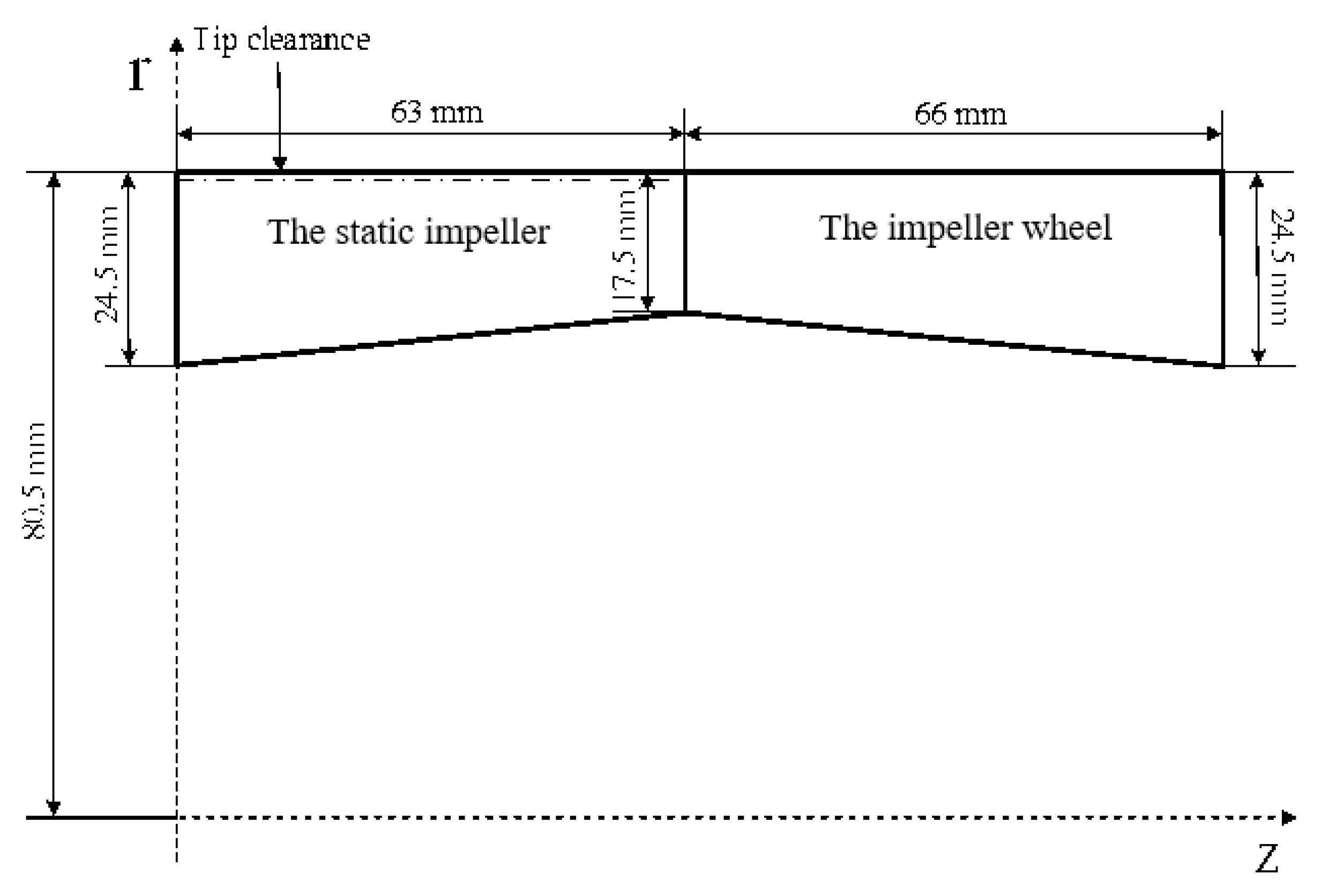
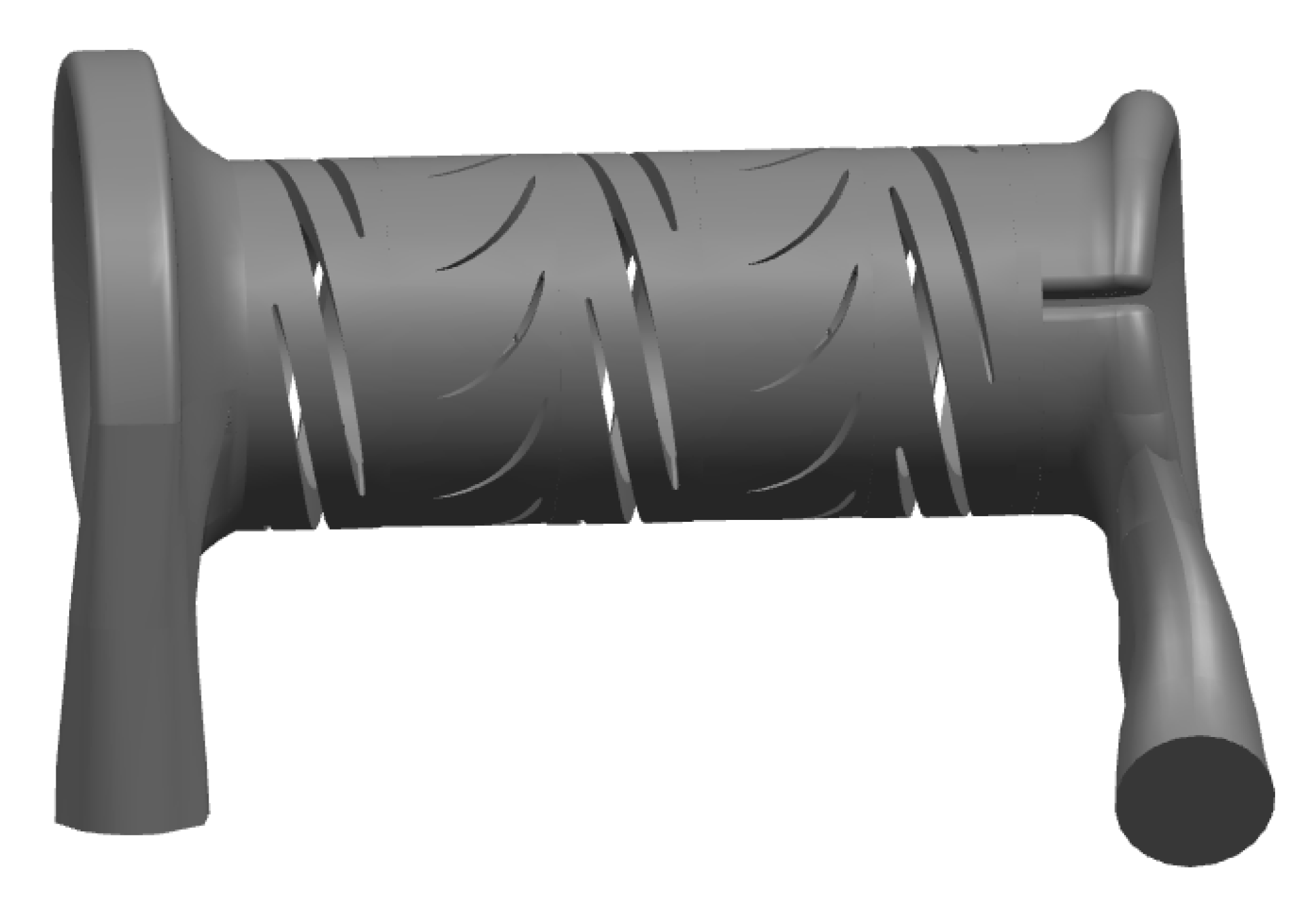
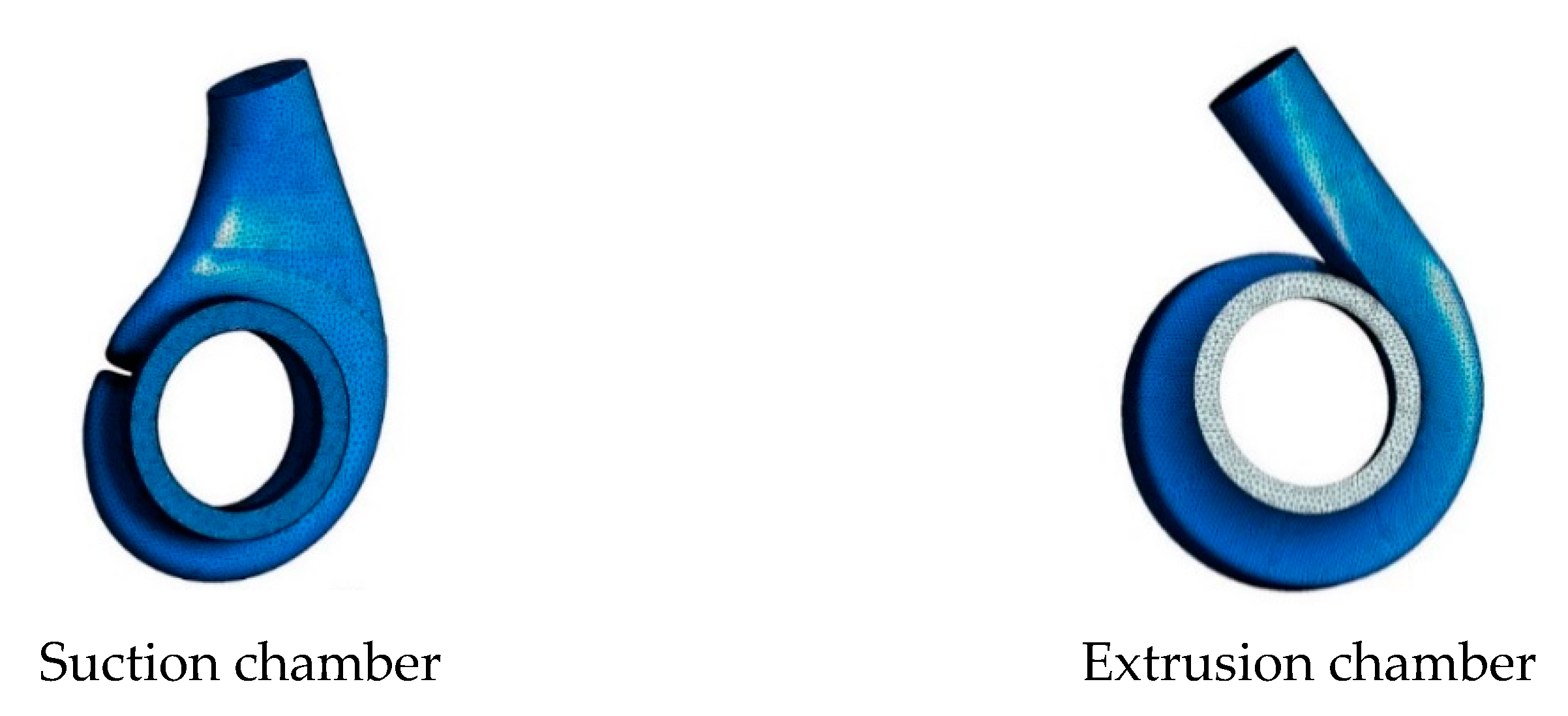
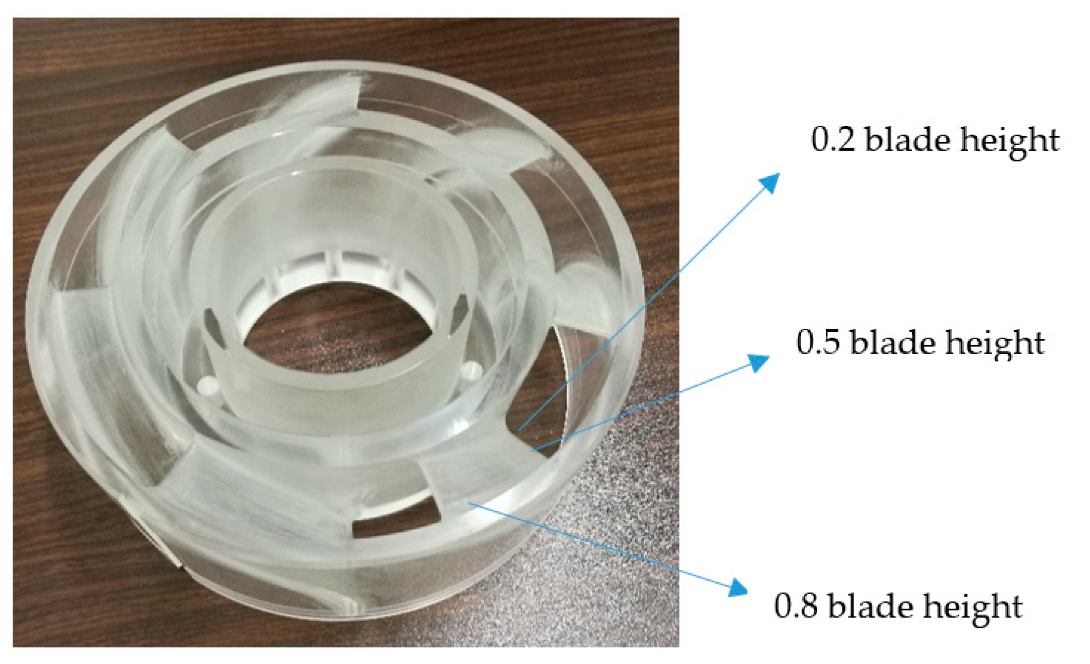
3.1. Simulation Model

Choosing the helical axial-flow multiphase pump as the research subject, and the relevant parameters of the pump are shown in Table 1. The size of the pump is shown in Figure 1. The three-dimensional modeling software is used to build the three-dimensional model of the impeller wheel, the static impeller, the suction chamber and the extrusion chamber, and then assembled as the finished model. The obtained three-dimensional model of the full flow field was shown in Figure 2.

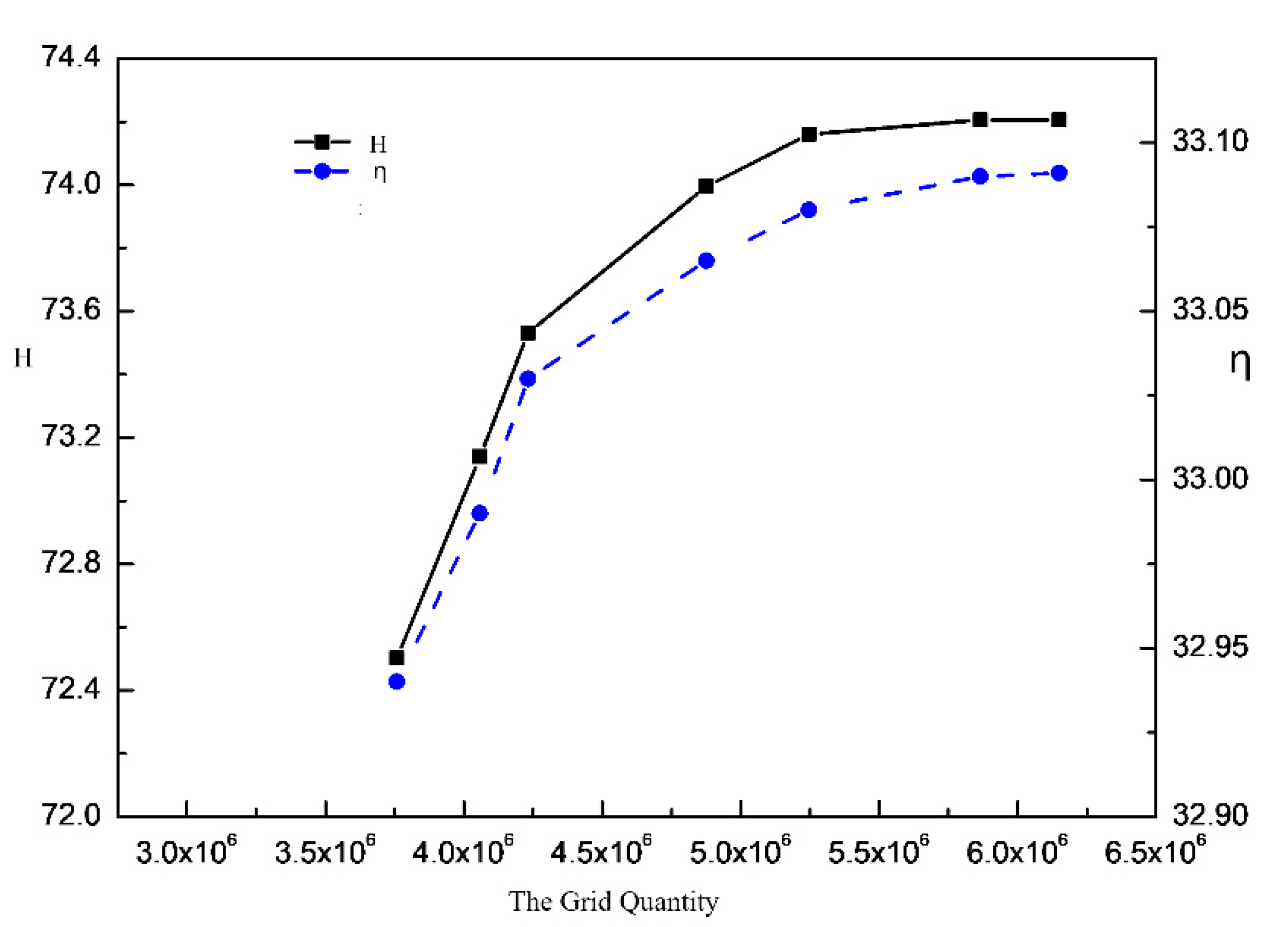
3.2. Mesh Generation and Verification of Irrelevance

The Suction Chamber, the extrusion chamber and three pressurizing units are considered as the fluid domains, and each pressurizing unit consists of an impeller wheel and a static impeller. The ICEM software is used to grid, the flow in the suction chamber and the extrusion chamber of the multiphase pump is relatively stable, therefore, an adaptive unstructured is used to grid partition, as shown in Figure 3. However, the flow in the supercharging unit is complex, so the impeller wheel and static impeller of the pump are divided by the structure grid, which are shown in Figure 4.
In order to eliminate the influence of mesh quality and mesh number on the numerical results and the computational speed, the grid independence was verified before the flow field calculation. Figure 5 shows the efficiency and head vary with the number of grids under the design condition. As can be seen from Figure 5, the head and efficiency increased by only 0.06% and 0.03%, respectively when the number of grids increased from 5.247 million to 6.150 million, which met the extraneous requirements of grids. The influence on the result is very small with the number of grids continuing to increase, and the computational cost would increase, so the 5.247 million is used as the final number of grids, among them, the number of grids in the impeller wheel and static impeller area is about 1.8 million and 1.1 million respectively. The grid quantity of suction chamber, extrusion chamber, the impeller wheel and the static impeller is respectively.

4. Numerical Calculation Method and Solution Setting

Used the standard SST k ω turbulence model, which is the most commonly used model in numerical calculation of the inlet flow in the multiphase pump. The inlet and outlet boundary conditions are respectively set as pressure inlet and quality outlet, the gas holdup ratio of gas-liquid two phases is converted to mass, and then the gas mass and liquid mass of the outlet are set respectively, assuming no energy exchange in gas and liquid two phases. The value of turbulent kinetic energy at the inlet and outlet of the pump and the dissipation rate of turbulent kinetic energy at the inlet and outlet are calculated according to the following formula:
k in = 0.005 u in 2
ε in = c u 3 / 4 k in 3 / 2 l
u in stands for the entrance velocity;
l = 0.07 D inlet , D inlet stands for the inlet diameter.
The wall surface of the impeller wheel adopted the rotating coordinate wall surface, while the others remained stationary. All walls of suction chamber, extrusion chamber, rotating impeller and static impeller are set as non-slip wall. The wall of rotating impeller was rotated and the other walls were stationary in the coordinate system. The reference pressure is set to 101,325 Pa and the convergence standard is set to 10−5. When the inlet-outlet pressure difference tends to be stable, considered that the standard of convergence of residual error is reached.

5. Experimental Setup and Verification

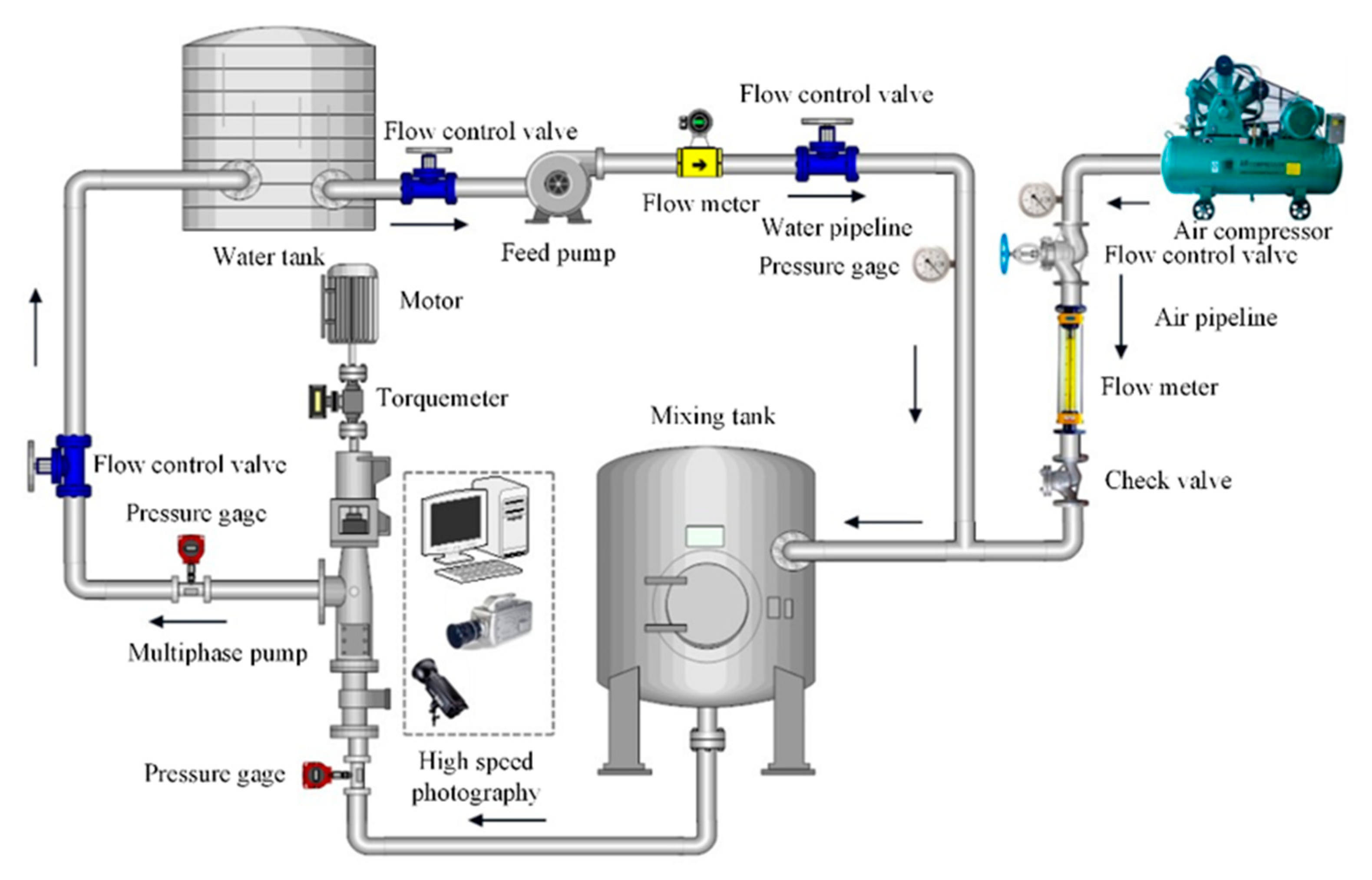
5.1. Experimental Setup

The experimental test system for the multiphase pump consists of the motor, multiphase pump, gas-liquid mixing tank, lubrication system, cooling system, control system, water supply system, gas supply system, test system, pipeline and valves, etc. The experimental system for the multiphase pump is shown in Figure 6.

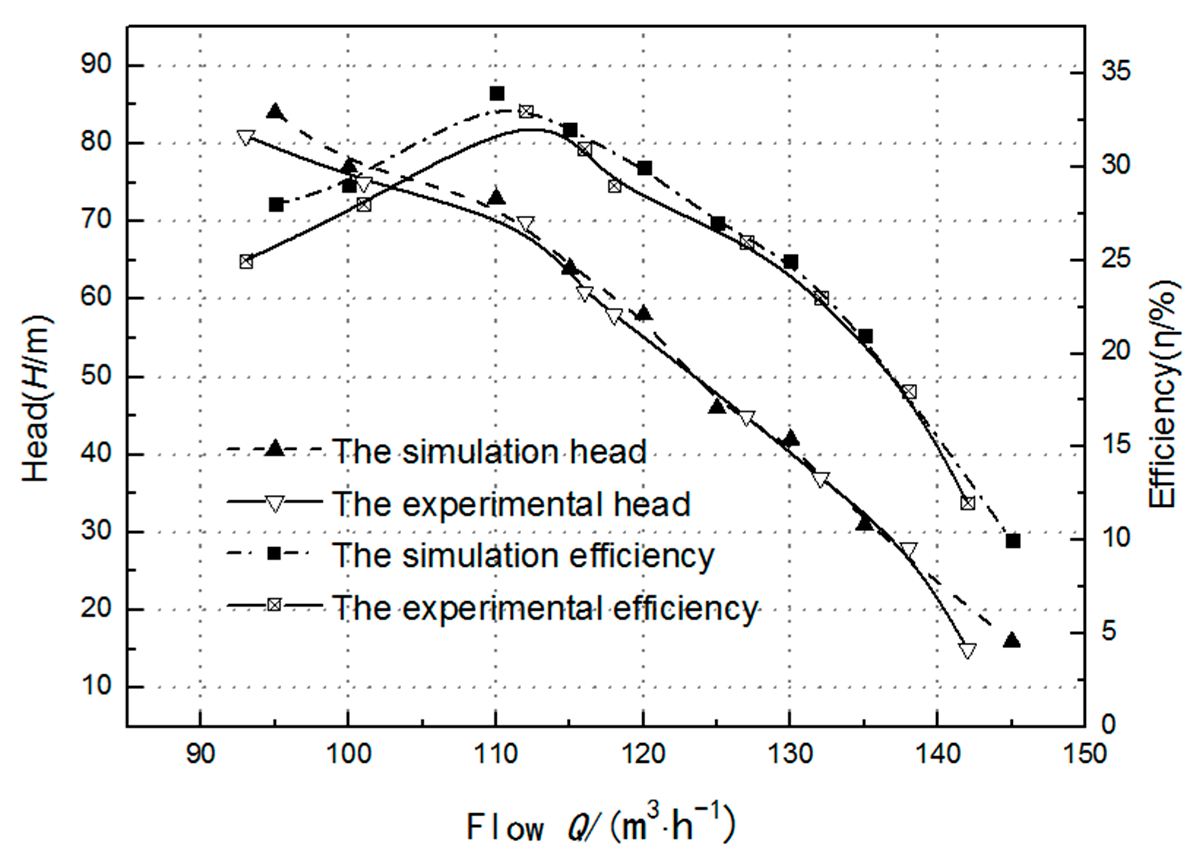
5.2. Experimental Verification

To verify the reliability of the numerical simulation, the results between simulation and experiment with same operating points are compared. Figure 7 shows comparison between the simulation and experiment, and the variation of the head and efficiency in simulation is agreed well with that in experiment. The experimental model and numerical calculation model in Figure 7 is a six-stage multiphase pump. In order to save calculation cost, a three-stage multiphase pump is selected for further research in this paper. Meanwhile, the relative errors of the head and efficiency at the optimal point are 4.1% and 4.1%, respectively. The maximum relative errors of the head and the efficiency are both no more than 5%, and this shows that the simulation in the present work is reliable.

6. Result Analysis

There are many influence factors of the energy conversion characteristics in the multiphase pump. In order to analyze the influence by each factor, the study was conducted under a single variable. Therefore, the energy loss characteristics in the static impeller of multiphase pump is studied under pure water condition.

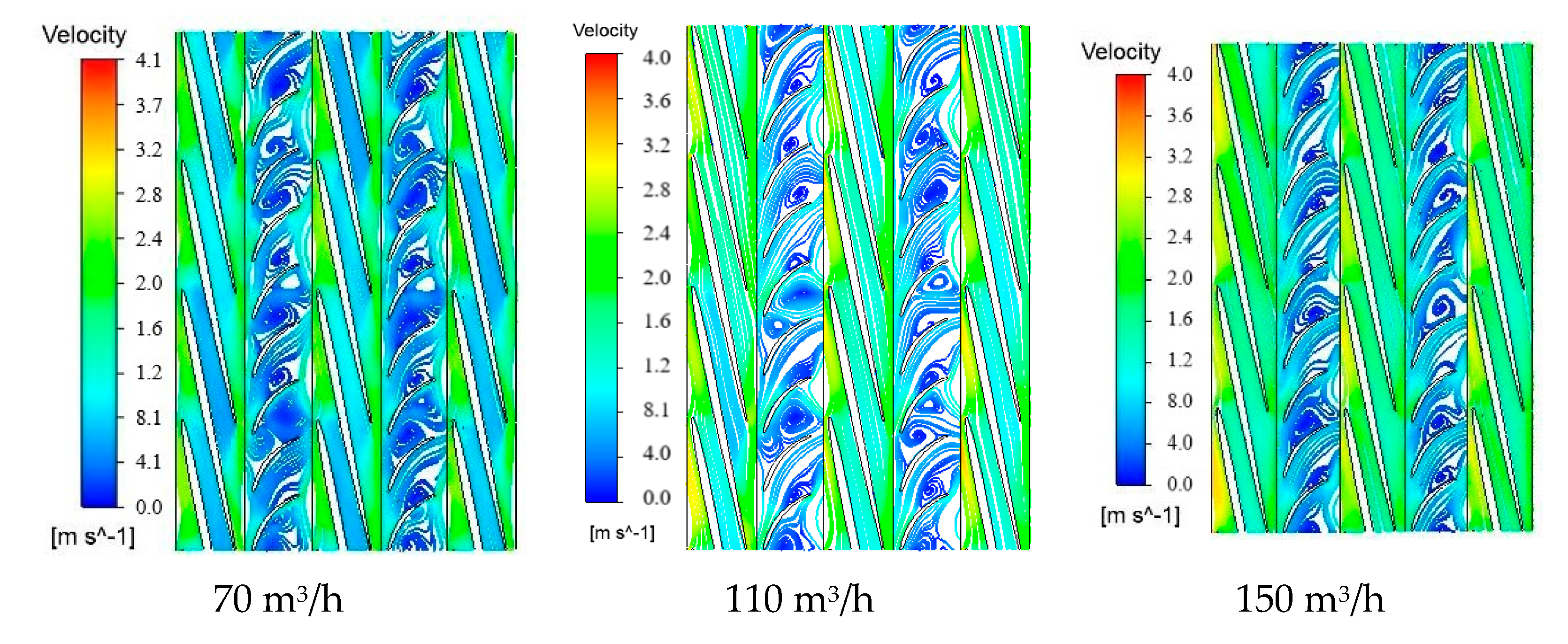
6.1. The Effects of Flow Rate on Velocity Vector in Static Impeller

The Figure 8 shows the different blade height position on the static impeller.
In Figure 9, Figure 10, Figure 11, Figure 12, Figure 13, Figure 14, Figure 15, Figure 16 and Figure 17, the color change from blue to red indicates the trend of velocity change from small to large.
Figure 9 shows the streamline distribution at 0.2 blade height of the pressurizing units of multiphase pump at different flow rate. It can be seen from Figure 9 that, the flow distribution in the flow passage of the static impeller of the multiphase pump is disorder, and a large number of axial vortexes appear near the static impeller near the outlet of the impeller wheel, which is mainly caused by the change of the direction of relative velocity of the fluid after the impeller wheel enters the static impeller. Compared with other flow rate, the axial vortex generated in the low-flow condition is larger. This is because in the low-flow condition, the constraint capacity of the blade on the fluid is weak and large vortexes are prone to appear. With the increase of flow rate, the fluid is constrained by the blade, so the vortex decreases relatively.
Figure 10 shows the streamline distribution at 0.5 blade height of the pressurizing units of multiphase pump at different flow rate. The figure shows that, the flow within the impeller wheel is evener, while there are still a lot of axial vortexes in the static impeller flow passage. What is more, under low-flow condition, the vortexes are almost filled of the static impeller passage, but with the increase of flow rate, the axial vortex moves to the static impeller exit, and the number of vortexes decreases gradually, even disappears in individual flow passage. The reason is the same as Figure 9 mentioned. It is also found that the vortex gradually approaches the suction surface of the blade with the increase of flow rate.
Figure 11 shows the streamline distribution of multiphase pump pressurizing 0.8 times the height of the blade under different flow rate. It can be seen from Figure 11 that the flow separation phenomenon occurs at the inlet of the static impeller under the low flow. That is mainly because the different inflow angle and blade angle cause the impact phenomenon, and this phenomenon disappears gradually with the flow increasing. Near the inlet of the static impeller appearing single or multiple vortexes, and with the flow increasing, the vortex become smaller or disappeared gradually.
Figure 12 shows the streamline distribution of the middle section of the inlet section of the first impeller wheel of the multiphase pump at different flow rate. The streamline distribution of the inlet section of the first impeller wheel of the multiphase pump has a great difference under different flow rate. Specifically, when the flow rate is 70 m3/h, the streamline distribution of the section is relatively uniform, and no vortex appear basically. When the flow rate is 110 m3/h, there are vortexes in individual flow passage, while the flow rate is 150 m3/h, only a few vortexes exist in the streamline of the section. This shows that with the increase of the flow rate, the flow in the inlet section of the first impeller wheel is gradually disorderly, and then gradually uniform. Meanwhile, it also shows the complexity and particularity of the flow in the first impeller wheel of the pump from the side.
Figure 13 shows the streamline distribution of the middle section of the middle section of the first impeller wheel of the multiphase pump at different flow rate. It can be seen from the Figure 13 that the streamline distribution of the middle section of the first impeller wheel is uniform, and the streamline distribution of the cross section almost does not change with the change of the flow rate, which indicates that the flow in the middle section of the first impeller wheel in the multiphase pump is good, and the flow rate has little influence on the flow characteristics of this part.
Figure 14 shows the streamline distribution of the middle section of the outlet section of the first impeller wheel of the multiphase pump at different flow rate. The figure shows that the streamline of the outlet section of the first impeller wheel is more uniform, and the flow in the impeller wheel of the multiphase pump is gradually uniform with the increase of the flow rate.
As can be seen from the synthesis of above three figures that from the impeller wheel inlet section, the middle section to the outlet section, the flow in the impeller wheel of the multiphase pump is first uniform and then disordered. In addition, the change of flow rate has a great influence on the flow in the inlet section of the first impeller wheel of the multiphase pump. However, the influence on the middle section and the outlet section of the pump is small, which indicates that the inlet section of the first impeller wheel is more sensitive to the change of flow rate.
Figure 15 shows the streamline distribution of the middle section of the inlet section of the first static impeller of the multiphase pump. It can be seen that with the increase of the flow rate, the size of the radial vortex in the section gradually decreases, and the center of the vortex gradually moves to the wheel hub. The vortex distribution in the inlet section of the first static impeller is random, and with the increase of the flow rate, the number of flow passages without radial vortex gradually increases. This indicates that with the increase of flow rate, the flow in the inlet section of the first static impeller of the multiphase pump is improved.
Figure 16 shows the streamline distribution of the middle section of the middle section of the first static impeller of the multiphase pump. It can be seen that the streamline distribution in the middle section of the first static impeller is disordered, and there are a lot of radial vortexes. Further, with the increase of the flow rate, the radial vortex of the section decreases first and then increases. In addition, it can be seen that the radial vortex in the section gradually moves towards the wheel hub with the increase of the flow rate.
Figure 17 shows the streamline distribution of the middle section of the outlet section of the first static impeller of the multiphase pump. It can be seen that the streamline of the outlet section of the first static impeller is more uniform under the design flow rate than small flow rate and large flow rate. Besides, large radial vortexes exist in the outlet passages of the first static impeller under the condition of low flow rate. The number of vortexes decreases as the flow rate increases to the design flow rate. Additionally, when the flow rate further increases to a large flow rate, the number of radial vortexes in the outlet section of the first static impeller of the multiphase pump gradually increases.
In the combination analysis from Figure 15, Figure 16 and Figure 17 can be seen that the streamline distribution in the first static impeller of the multiphase pump is more disorderly than that in the first impeller wheel. It can be seen from the streamline distribution of the inlet section, middle section and outlet section of the first static impeller that at different flow rate, the flow in different sections of the first static impeller is relatively chaotic, and the size of the radial vortex gradually increases from the inlet to the outlet section. Therefore, the flow in the first static impeller is more dramatically affected by the flow rate change than that in the impeller wheel, and the flow in the static impeller is more complex, therefore, it is of theoretical significance to study the energy loss in the static impeller to improve the performance of the multiphase pump.

6.2. Analysis of Energy Losses in Static Impeller of Multiphase Pump

Figure 18 shows variation of various energy losses in the static impeller at different flow rate. It can be seen that, with the increase of the flow rate from 70 to 150 m3/s, the overall energy loss in the static impeller shows a decreasing trend, but the shock loss changes very little, and the contraction loss shows an upward trend. Under the low floe rate (70 m3/s), the fraction loss and the turbulence dissipation loss are the maximum values. It can also be seen that friction loss accounts for the largest proportion of all kinds of losses, follow by turbulence dissipation loss, and shock loss and contraction loss are the least.
Figure 19 shows the proportion of each energy loss in the static impeller at different flow rate. It can be seen that with the change of the flow rate, the proportion of the friction loss and the turbulence loss shows the opposite change rule, the proportion of the fraction loss increases gradually with the increase of the flow rate. It also can be seen that, at a different flow rate, the energy loss in the static impeller is mainly the friction losses and the turbulence dissipation loss, especially the friction loss accounted for more than 50%, and the sum of the shock loss and the contraction loss does not exceed 20%

6.3. Comparative Analysis of Energy Loss between Different Stages of Static Impeller

Figure 20 shows the variation trend of energy loss in each stage static impeller at different flow rate. It shows that the energy loss in the static impeller at all stages shows a decreasing trend with the increase of flow rate, at the low flow rate (70 m3/s), the energy loss in each stage static impeller is the largest. It can be seen that with the increase of the flow rate, the flow performance in the static impeller of the multiphase pump gradually improves, and the hydraulic loss in the static impeller also decreases correspondingly.
Figure 21 shows the proportion of the energy loss in the first and second static impellers to the total energy loss at different flow rate. The proportion of energy loss in the first and second static impellers has little difference under different flow rate, and both of them are about 50%, indicating that the position of the static impeller has little influence on the flow condition and energy loss in the static impeller.
Figure 22a shows the shock loss of the static impeller at different flow rate. It can be seen that with the increase of the flow rate, the shock loss at the inlet of the first static impeller first decreases and then increases, and the shock loss fluctuates within a very small range around 0.55 m, and the maximum variation value is not more than 0.01 m.
Figure 22b shows the friction loss of the static impeller at different flow rate. Under the different flow rate, compared with the shock loss in the static impeller, the friction loss in the static impeller is much larger, the shock loss in each stage static impeller is less than 1 m, but the friction loss is more than 40 m. It also can be seen the friction loss in each stage static impeller is not much different, and the change trend of the friction loss in all stages of the static impeller with the flow rate is basically the same, as the flow rate increases from 70 to 130 m3/s, the energy loss in each stage static impeller gradually decreases, when the flow rate continues to increase to 150 m3/s, the loss slightly increases.
Figure 22c shows the contraction loss of the static impeller at different flow rate. It shows that the contraction loss in each stage of the static impeller increases gradually with the increase of flow rate, but the contraction loss in the second static impeller increases steadily, and the contraction loss in the first static impeller fluctuates greatly. When the flow rate is smaller than the design flow rate (110 m3/s), the contraction loss in the first static impeller is smaller than that in the second static impeller. Moreover, when the flow rate is larger than the design flow rate, the contraction loss in the first static impeller is greater than that in the second static impeller.
Figure 22d shows the turbulence dissipation loss of the static impeller at different flow rate. Under the different flow rate, compared with the contraction loss in the static impeller, the turbulence dissipation loss in the static impeller is much larger, the contraction loss in each stage static impeller is less than 1 m, but the turbulence dissipation loss is more than 10 m. It also can be seen that, with the increase of flow rate, the turbulence dissipation loss in each stage of the static impeller decreases gradually, and the turbulence dissipation values in each stage of static impeller are getting closer gradually.

7. Conclusions

(1).
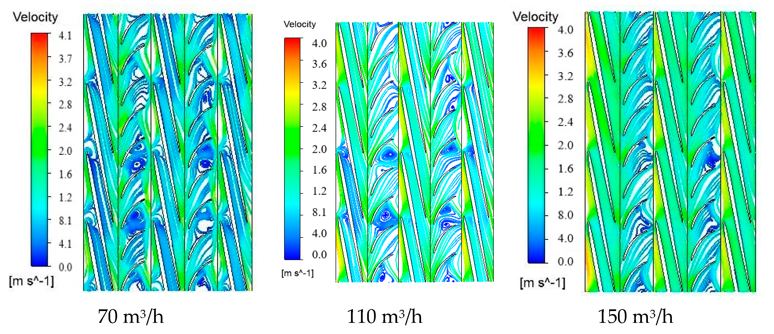
The flow within the impeller wheel is more uniform than the static impeller, and larger axial vortexes appear in the static impeller, and under the condition of low flow rate, the vortex in the static impeller of the multiphase pump almost cover the entire flow passage of the impeller, this is because at this condition, the constraint ability of the blade to the fluid is weak, and large vortices are prone to appear. However, with the increase of the flow rate, the vortex gradually decreases even basically disappear in individual flow passage. Compared with the impeller wheel, the effect of the flow rate on the flow within the first static impeller is greater.
(2).
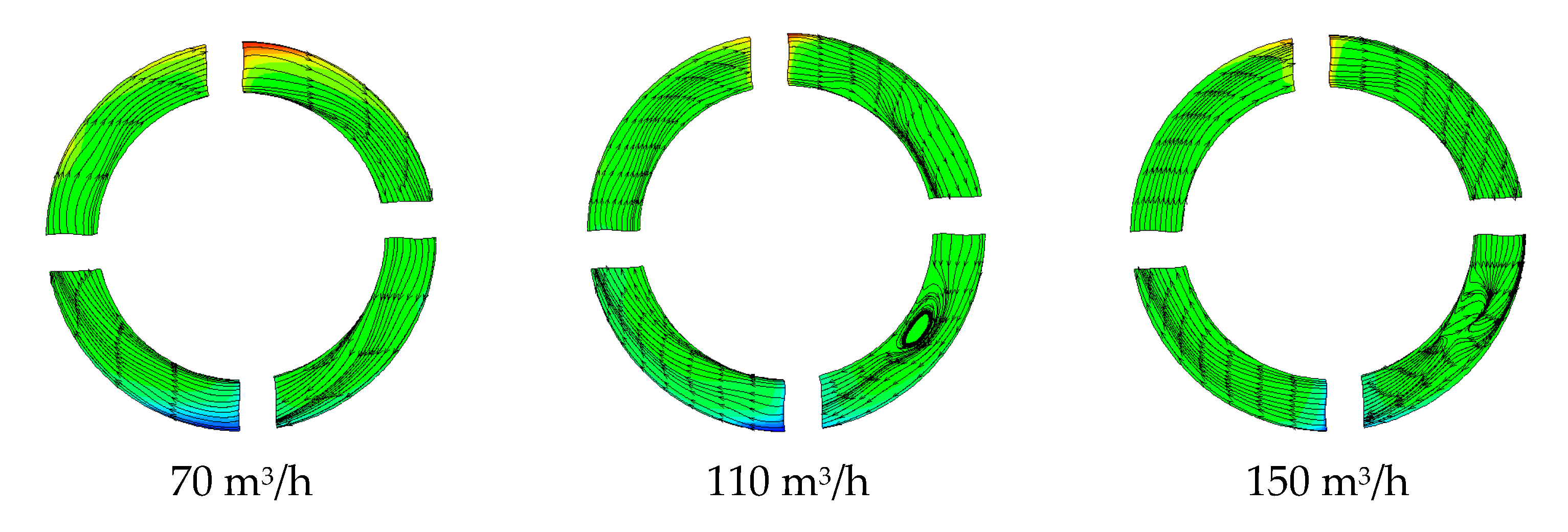
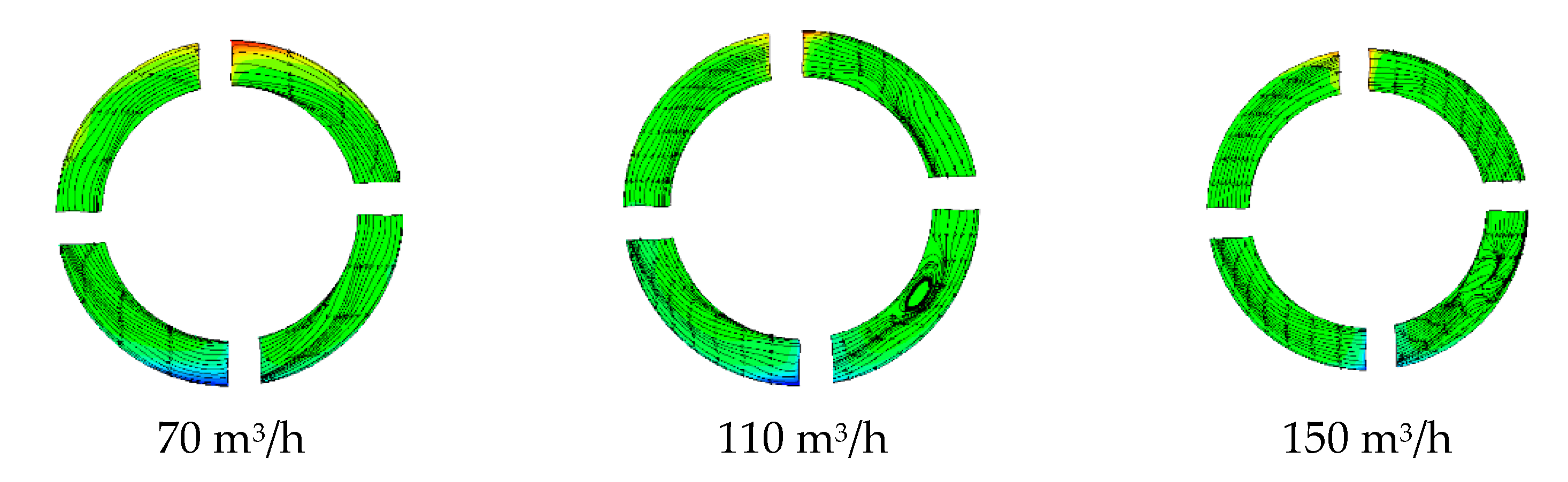
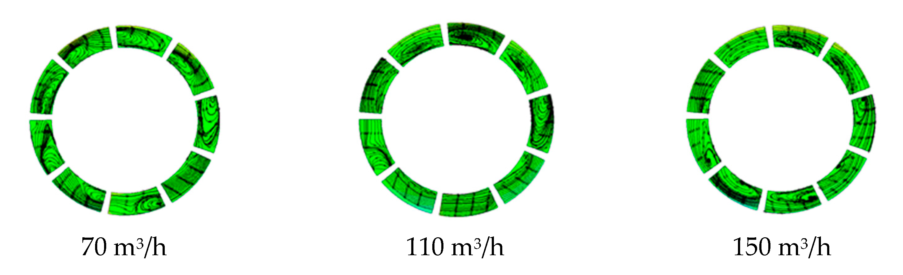
The streamline distribution in the cross section of the impeller wheel of the multiphase pump is more uniform than that in the static impeller. At different flow rate, the flow in different areas of the first static impeller of the multiphase pump is relatively chaotic, and the size of the radial vortex gradually increases from the inlet to the outlet section. It can be seen that the flow in the first static impeller is more obviously affected by the flow change than that in the impeller wheel, and the flow in the static impeller is more complex.
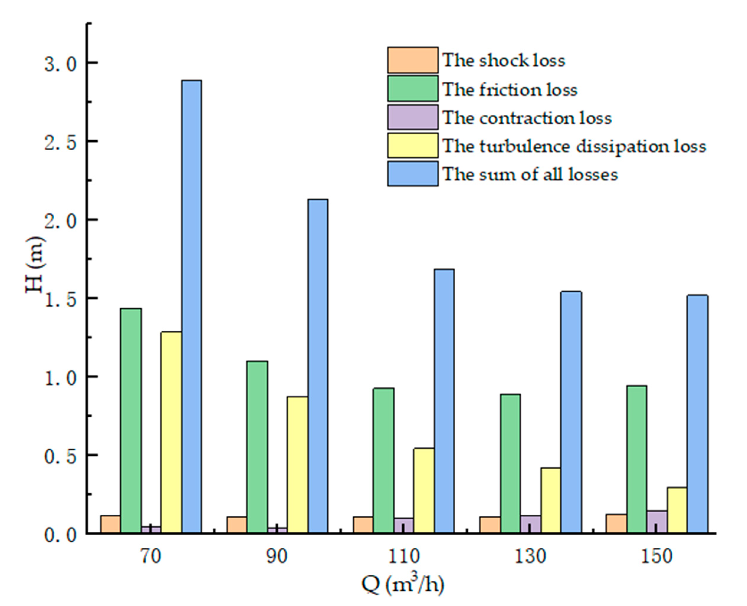
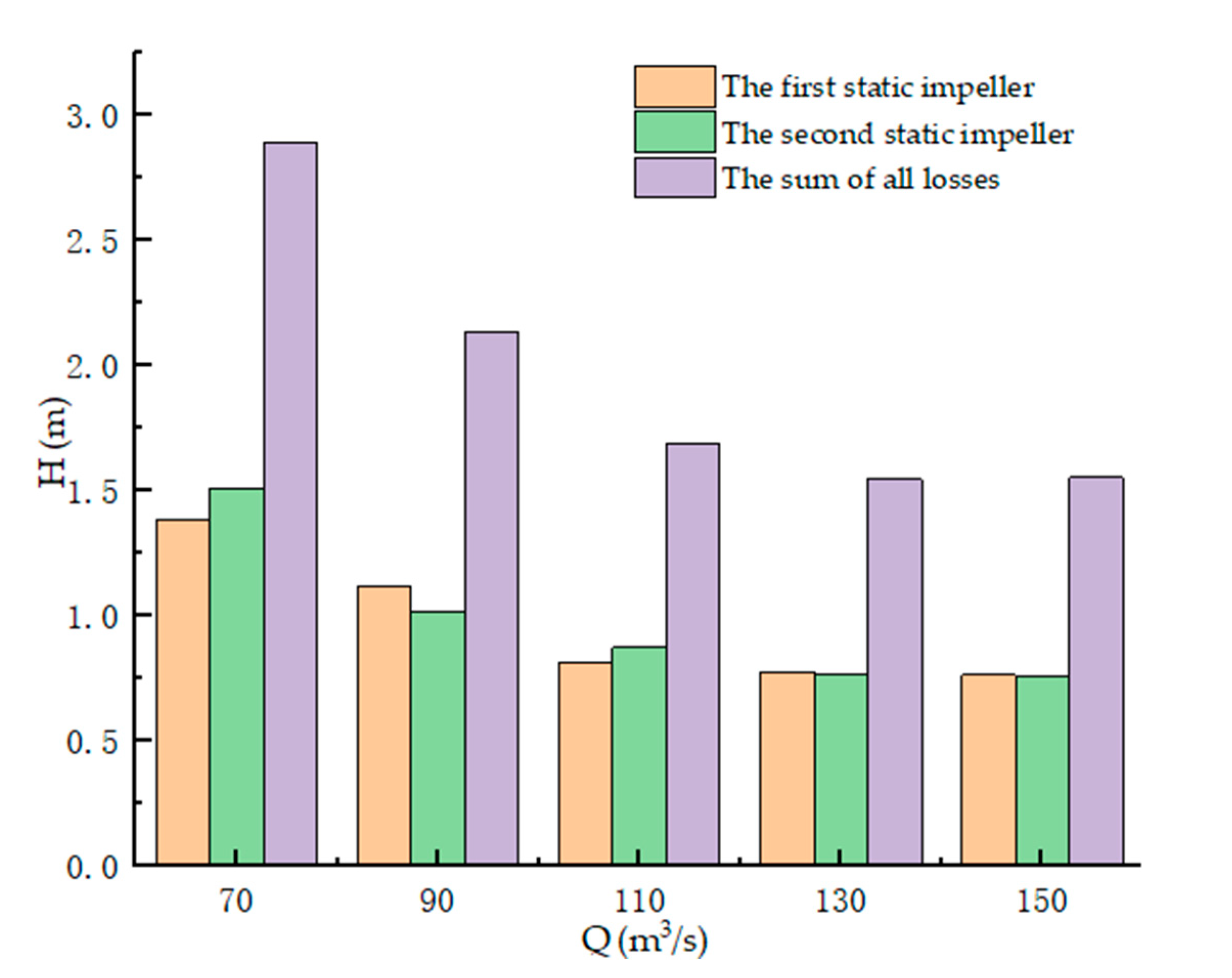
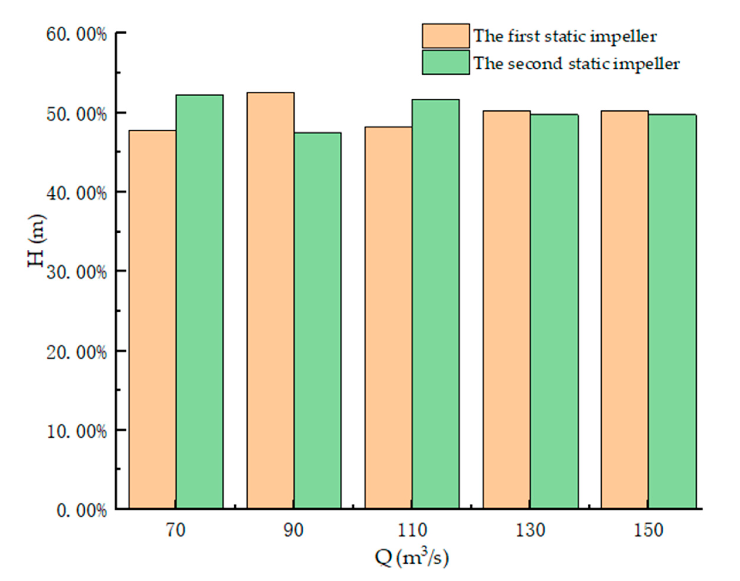
(3).
At the different flow rate, the energy loss in the static impeller is mainly the turbulence dissipation loss and the friction loss, the inlet shock loss and the contraction loss accounted for less than 20%. With the increase of flow rate, the proportion of the inlet shock loss, the friction loss and the contraction loss in the static impeller increases gradually, and the proportion of the turbulence dissipation loss in the static impeller decreases gradually. The proportion of energy loss in the first and second static impellers has little difference under different flow rate, and both of them are about 50%, indicating that the position of the static impeller has little influence on the flow condition and energy loss in the static impeller.
(4).
It can be known from the analysis of the above, the energy loss in multiphase pumps is mainly caused by the change of the flow within the static impeller, and found that the changing rule of energy losses in the static impeller with different flow rate, the different level higher and so on. However, if we simply analyzed the source and the regularity, and did not put forward the solution, in the subsequent research, the performance can be optimized to improve the efficiency of the multiphase pump.
(5).
Because the vortex in the multiphase pump is mainly concentrated in the static impeller, this paper mainly studies the flow characteristics and energy loss in the static impeller, which has important guiding significance to reduce the vortex in the static impeller and improve the hydraulic efficiency of the multiphase pump.

Author Contributions

Conceptualization, Z.J., X.L. and G.S.; methodology, Z.J.; software, Z.J., G.S. and H.L.; validation, G.S., Z.J. and X.L.; formal analysis, G.S. and H.L.; investigation, H.L. and G.S.; resources, Z.J. and G.S.; data curation, G.S. and H.L.; writing—original draft preparation, Z.J. and H.L.; writing—review and editing, Z.J. and H.L.; visualization, H.L.; supervision, X.L.; project administration, Z.J. and G.S.; funding acquisition, G.S. All authors have read and agreed to the published version of the manuscript.

Funding

This work was supported by the National Key Research and Development Program (2018YFB0905200), Open Research Fund Program of State key Laboratory of Hydroscience and Engineering (sklhse-2021-E-03), Education Department Key Project of the Sichuan province of China (Grant No. 17ZA0366), the Key Scientific Research Fund of Xihua University of China (Grant No. Z1510417), Open Research Subject of Key Laboratory of Fluid and Power Machinery, Ministry of Education (Grant No. LTDL2020-008), the National Natural Science Foundation of China (Grant Nos. 52079140,51479093), the National Key Research and Development Program of China (Grant No. 2017YFC0404200), the Key Research and Development Program of Tianjin (Grant No. 18YFZCSF00310), the Key Laboratory of Fluid and Power Machinery (Xihua University) Ministry of Education (Grant No. SZJJ-2018-125).

Institutional Review Board Statement

Thank you for your advice, the study did not involve humans or animals.

Informed Consent Statement

The study did not involve humans.

Data Availability Statement

The study did not report any data.

Conflicts of Interest

The authors declare no conflict of interest.

Nomenclature

ω stands for the turbulent kinetic energy dissipation ratio; ρ stands for the medium density; μ stands for the viscosity; G k stands for the turbulent kinetic energy; G ω stands for the ω equation; D ω stands for the orthogonal divergence term; α k stands for the void fraction; ρ k stands for the density; w k stands for the velocity of k phase. τ stands for the viscous stress tensor; M k stands for the interphase force; f k stands for the mass force; V1 stand for the absolute speed of static impeller inlet; Z, λ stand for number of blades, linear loss coefficient; V a stands for the average of absolute velocity, V a = 0.5 ( V 1 + V 2 ) , V 2 stands for the absolute velocity in the static impeller outlet; l a stands for hydraulic length of flow passage, l a = D 2 + D 1 2 ( sin β 2 + sin β 1 ) ; D a stands for average of the flow passage diameter, D a = D 2 + D 1 2 ; ε stands for turbulence dissipation rate; the value of k1~k4 are selected through a lot of calculations, experiments and analysis from the predecessors. k1, k2, k3, k4 are 0.008, 0.0202, 0.162, 0.1, respectively; u in stands for the entrance velocity; l = 0.07 D inlet , D inlet stands for the inlet diameter.

References

  1. Valizadeh, K.; Farahbakhsh, S.; Bateni, A.; Zargarian, A.; Davarpanah, A.; Alizadeh, A.; Zarei, M. A parametric study to simulate the non-Newtonian turbulent flow in spiral tubes. Energy Sci. Eng. 2020, 8, 134–149. [Google Scholar] [CrossRef] [Green Version]
  2. Shi, G.; Yan, D.; Liu, X.; Xiao, Y.; Shu, Z. Effect of the Gas Volume Fraction on the Pressure Load of the Multiphase Pump Blade. Processes 2021, 9, 650. [Google Scholar] [CrossRef]
  3. Yousefizadeh Dibazar, S.; Salehi, G.; Davarpanah, A. Comparison of Exergy and Advanced Exergy Analysis in Three Different Organic Rankine Cycles. Processes 2020, 8, 586. [Google Scholar] [CrossRef]
  4. Esfandi, S.; Baloochzadeh, S.; Asayesh, M.; Ehyaei, M.A.; Ahmadi, A.; Rabanian, A.A.; Das, B.; Costa, V.A.; Davarpanah, A. Energy, Exergy, Economic, and Exergoenvironmental Analyses of a Novel Hybrid System to Produce Electricity, Cooling, and Syngas. Energies 2020, 13, 6453. [Google Scholar] [CrossRef]
  5. Wang, C.; Zhang, Y.; Zhang, J.; Zhu, J. Flow pattern recognition inside a rotodynamic multiphase pump via developed entropy production diagnostic model. J. Pet. Sci. Eng. 2020, 194, 107467. [Google Scholar] [CrossRef]
  6. Fernández, J.; Marcos, A.; Barrio, R.; Blanco, E.; Parrondo, J. Studies of the flow of air in a mixed-flow pump using numerical simulations. Proc. Inst. Mech. Eng. Part A J. Power Energy 2011, 225, 647–654. [Google Scholar] [CrossRef]
  7. Bing, H.; Tan, L.; Cao, S.; Lu, L. Prediction method of impeller performance and analysis of loss mechanism for mixed-flow pump. Sci. China (Technol. Sci.) 2012, 55, 1988–1998. [Google Scholar] [CrossRef]
  8. Xu, Y.; Tan, L.; Liu, Y.; Hao, Y.; Zhu, B.; Cao, S. Pressure fluctuation and flow pattern of a mixed-flow pump under design and off-design conditions. Proc. Inst. Mech. Eng. Part C J. Mech. Eng. Sci. 2018, 232, 2430–2440. [Google Scholar] [CrossRef]
  9. Oh, H.W. Design parameter to improve the suction performance of mixed-flow pump impeller. Proc. Inst. Mech. Eng. Part A J. Power Energy 2010, 224, 881–887. [Google Scholar] [CrossRef]
  10. Yang, X.; Xia, Y.; Jin, L.; Cao, F. Experimental Study on Pumping Behavior of Twin-Screw Multiphase Pump. J. Xi’an Jiaotong Univ. 2013, 47, 30–35. [Google Scholar]
  11. Li, C.; Luo, X.; Feng, J.; Zhu, G.; Yan, S. Effect of Diversion Cavity Geometry on the Performance of Gas-Liquid Two-Phase Multiphase pump. Energies 2020, 13, 1882. [Google Scholar] [CrossRef]
  12. Li, C.; Luo, X.; Feng, J.; Sun, H.; Zhu, J.; Xue, G. Investigation on the influence of inlet gas volume fraction on the performance of deep-sea multiphase pump. Chin. J. Hydrodyn. 2020, 35, 248–257. [Google Scholar]
  13. Zhang, R.; Wang, S.; Osman Juma S A1. Transient Gas Liquid Flow in Helical Axial Pump Diffuser and Its DMD Analysis. Trans. Chin. Soc. Agric. Mach. 2020, 51, 118–126. [Google Scholar]
  14. Li, C.; Luo, X.; Feng, J.; Zhu, G.; Xue, Y. Effects of Gas-Volume Fractions on the External Characteristics and Pressure Fluctuation of a Multistage Multiphase pump. Appl. Sci. 2020, 10, 582. [Google Scholar] [CrossRef] [Green Version]
  15. Jinya, Z.; Shujie, C.; Hongwu, Z.; Ke, Y.; Rui, Q. Numerical Investigation of Compessible Flow in a Three-stage Helico-axial Multiphase Pump. Trans. Chin. Soc. Agric. Mach. 2014, 45, 89–95. [Google Scholar]
  16. Wang, Y. Study on design and selection of twin-screw multiphase pump for offshore platform. Pump Technol. 2017, 5, 24–27. [Google Scholar]
  17. Hu, Y.; Hu, C.C.; Zhang, J.; Qu, Z.C. Optimization Research on Structure of Synchronal Rotary Multiphase Pumps. Compress. Technol. 2016, 4, 16–21. [Google Scholar]
  18. Wang, K.; Hu, B.; Cao, F.; Wang, W.Y.; Li, Q.G.; Xing, Z.W. Leakage Analysis and Effect on Volumetric Efficiency of Twin-screw Multiphase Pump with Higher Gas Volume Fractions. Fluid Mach. 2011, 39, 10–16. [Google Scholar]
  19. Li, X.Q.; Wang, J.; Zhao, P.; Yu, G.C. A random fractal model of gas-liquid distribution in multiphase pump. J. Guangxi Univ. (Nat. Sci. Ed.) 2010, 35, 756–761. [Google Scholar]
  20. Zhang, J.; Cai, S.; Zhu, H. Visualization Test for Flow Field of Gas-liquid Two-phase in the Entrance of Rotodynamic Multiphase Pump. J. Mech. Eng. 2015, 51, 184–190. [Google Scholar] [CrossRef]
  21. Li, D.Y.; Gong, R.Z.; Wang, H.J.; Fu, W.W.; Wei, X.Z.; Liu, Z.S. Fluid flow analysis of drooping phenomena in pump mode for a given guide vane setting of a pump-turbine model. J. Zhejiang Univ. Sci. A (Appl. Phys. Eng.) 2015, 16, 851–863. [Google Scholar] [CrossRef] [Green Version]
  22. Minguan, Y.; Yu, M.; Bo, G.; Dan, N.; Zhong, L. Design of axial-flow impeller guide cone and simulation on hydraulic performance of its passage. Trans. Chin. Soc. Agric. Eng. 2015, 31, 81–88. [Google Scholar]
  23. Rennian, L.; Zhengjing, S.; Wei, H.; Hui, Q.; Qifei, L. Energy loss analysis of impeller flow of screw centrifugal pump. Trans. Chin. Soc. Agric. Mach. 2014, 45, 125–130. [Google Scholar]
  24. Jin, Y.; Zhang, D.; Shi, L.; Sheng, X.; Shi, W.; Wang, D. Numerical investigation of flow structure and energy loss in impeller side chamber of molten salt pump. Acta Energ. Sol. Sin. 2020, 41, 326–334. [Google Scholar]
  25. Shu, X.; Ren, Y.; Wu, D.; Zhu, Z.; Mou, J. Energy loss and unsteady flow characteristics in a self-priming pump. J. Hydraul. Eng. 2019, 50, 1010–1020. [Google Scholar]
  26. Shi, G.; Li, H.; Liu, Z.; Wang, S. Effect of Hub Ratio on Flow Field Characteristics in Multiphase Pump. Fluid Mach. 2020, 48, 49–54. [Google Scholar]
  27. Shi, G.; Wang, S.; Yao, X.; Li, H. Effect of cavitation on flow characteristics in multiphase pump. Water Resour. Power 2020, 38, 156–159. [Google Scholar]
  28. Shi, G.; Liu, Z.; Xiao, Y.; Wang, Z.; Luo, Y.; Luo, K. Energy conversion characteristics of multiphase pump impeller analyzed based on blade load spectra. Renew. Energy 2020, 157, 9–23. [Google Scholar] [CrossRef]
  29. Pei, J.; Osman, M.K.; Wang, W.; Yuan, J.; Yin, T.; Appiah, D. Unsteady flow characteristics and cavitation prediction in the double-suction centrifugal pump using a novel approach. Proc. Inst. Mech. Eng. Part A J. Power Energy 2020, 234, 283–299. [Google Scholar] [CrossRef]
  30. Pei, J.; Zhang, F.; Appiah, D.; Hu, B.; Yuan, S.; Chen, K.; Asomani, S.N. Performance prediction based on effects of wrapping angle of a side channel Pump. Energies 2019, 12, 139. [Google Scholar] [CrossRef] [Green Version]
  31. Suh, J.W.; Kim, J.W.; Choi, Y.S.; Kim, J.H.; Joo, W.G.; Lee, K.Y. Multi-objective optimization of the hydrodynamic performance of the second stage of a multi-phase pump. Energies 2017, 10, 1334. [Google Scholar] [CrossRef] [Green Version]
Figure 1. Impeller and diffuser meridian parameters.
Processes 09 01025 g001
Figure 2. The three-dimensional model of the multiphase pump.
Processes 09 01025 g002
Figure 3. Mesh generation of suction chamber and extrusion chamber.
Processes 09 01025 g003
Figure 4. Mesh generation of supercharged unit.
Processes 09 01025 g004
Figure 5. The grid independence verification.
Processes 09 01025 g005
Figure 6. Multiphase pump experimental system.
Processes 09 01025 g006
Figure 7. Comparison of experimental and numerical results.
Processes 09 01025 g007
Figure 8. Diagram of different blade heights.
Processes 09 01025 g008
Figure 9. The streamline distribution at 0.2 blade height of multiphase pump pressurizing units.
Processes 09 01025 g009
Figure 10. The streamline distribution at 0.5 blade height of multiphase pump pressurizing units.
Processes 09 01025 g010
Figure 11. The streamline distribution at 0.8 blade height of multiphase pump pressurizing units.
Processes 09 01025 g011
Figure 12. The streamline distribution of the middle section of the inlet section of the first impeller wheel.
Processes 09 01025 g012
Figure 13. The streamline distribution of the middle section of the middle section of the first impeller wheel.
Processes 09 01025 g013
Figure 14. The streamline distribution of the middle section of the outlet section of the first impeller wheel.
Processes 09 01025 g014
Figure 15. The streamline distribution of the middle section of the inlet section of the first static impeller.
Processes 09 01025 g015
Figure 16. The streamline distribution of the middle section of the middle section of the first static impeller.
Processes 09 01025 g016
Figure 17. The streamline distribution of the middle section of the outlet section of the first static impeller.
Processes 09 01025 g017
Figure 18. The energy losses of the static impeller at different flow rate.
Processes 09 01025 g018
Figure 19. The proportion of each energy loss in the static impeller at different flow rate.
Processes 09 01025 g019
Figure 20. The energy loss of the different stages static impeller at different flow rate.
Processes 09 01025 g020
Figure 21. The proportion of each static impeller’s energy losses at different flow rate.
Processes 09 01025 g021
Figure 22. (ad) Variation law of hydraulic loss in static impeller of multiphase pump.
Processes 09 01025 g022
Table 1. The performance geometric parameters of the multiphase pump.
ParameterNumerical Value
Flow rate Q d / ( m 3 / h ) 110
Head H / m 85
Design rotate speed n / ( r / m ) 3000
Stage6
Publisher’s Note: MDPI stays neutral with regard to jurisdictional claims in published maps and institutional affiliations.

