Abstract
(1) Background: Bioreactors mimic the natural environment of cells and tissues by providing a controlled micro-environment. However, their design is often expensive and complex. Herein, we have introduced the development of a low-cost compression bioreactor which enables the application of different mechanical stimulation regimes to in vitro tissue models and provides the information of applied stress and strain in real-time. (2) Methods: The compression bioreactor is designed using a mini-computer called Raspberry Pi, which is programmed to apply compressive deformation at various strains and frequencies, as well as to measure the force applied to the tissue constructs. Besides this, we have developed a mobile application connected to the bioreactor software to monitor, command, and control experiments via mobile devices. (3) Results: Cell viability results indicate that the newly designed compression bioreactor supports cell cultivation in a sterile environment without any contamination. The developed bioreactor software plots the experimental data of dynamic mechanical loading in a long-term manner, as well as stores them for further data processing. Following in vitro uniaxial compression conditioning of 3D in vitro cartilage models, chondrocyte cell migration was altered positively compared to static cultures. (4) Conclusion: The developed compression bioreactor can support the in vitro tissue model cultivation and monitor the experimental information with a low-cost controlling system and via mobile application. The highly customizable mold inside the cultivation chamber is a significant approach to solve the limited customization capability of the traditional bioreactors. Most importantly, the compression bioreactor prevents operator- and system-dependent variability between experiments by enabling a dynamic culture in a large volume for multiple numbers of in vitro tissue constructs.
1. Introduction
Tissue engineering approaches have been recently applied to the design of in vitro models, which are employed to explore fundamental aspects of cell functions and to identify cellular mechanisms involved in wound healing, aging processes or disease progression. Mechanical forces that cells are subjected to their natural micro-environment must be considered while designing experiments with the in vitro models [1]. This fact led researchers to develop bioreactor systems which are developed to mimic the physiological environment of tissues and help to investigate the gap between cellular processes and mechanical loading experienced by cells. The usage of bioreactors confers an advantage of culturing the in vitro models in a more realistic and controlled environment than a simple in vitro conventional culture. This advantage has arisen the prevalence of bioreactor usage and a large variety of bioreactor systems have been developed for addressing a particular cell and tissue phenotype [2].
The design of tissue engineering bioreactors should be completed in a way that they support tissue development, maintain cell viability and cellular functions and provide biochemical and physical signals. Furthermore, there are common principles that should be considered such as easy assembly, sterility, biocompatible material choice, non-toxicity, and usage of pumps or actuators [3]. The incorporation of these principles makes tissue engineering bioreactor systems more expensive and complex. Moreover, current bioreactor systems are not highly customizable and exhibit a lack of force measurement capability [4]. Therefore, there is a huge demand for the design of customizable, low-cost, programmable bioreactor systems with force measurement ability.
The selection of mechanical loading type in the development of bioreactors is determined by which tissue is being examined and what type of mechanical loading that tissue maintains in its physiological behaviour. In the literature, there are several types of bioreactors reported that apply tension, compression, shear using uniaxial, biaxial, and multiaxial loading procedures to the in vitro models to enhance necessary cellular processes and to examine tissue and disease models. Bilgen et al. [5] designed a loading device that applies uniaxial or biaxial mechanical strain for long-term in vitro cultivation of tissue-engineered constructs. Hoffmann et al. [6] developed a perfusion compression bioreactor and proved that dynamic compression loading enhances the maturation process of mesenchymal stem cells toward late hypertrophic chondrocytes, as well as the extracellular matrix mineralization during hypertrophy of cartilaginous constructs. A novel bioreactor system that incorporates perfusion fluid flow and hydrostatic compression has been introduced by Orr et al. [7] demonstrating that this system facilitates the viable growth of cells. Subramanian et al. [8] designed a tensile bioreactor that is capable of applying precise and homogeneous uniaxial strains to 3D cell-encapsulated collagen constructs at physiological loading strains.
Compression and shear bioreactors are mainly developed for cartilage tissue, since they are the main types of mechanical loading in the natural environment of cartilage tissue. The effects of these loads on the cartilage constructs have been extensively examined in the literature to improve the understanding of the mechanical micro-environment of cartilage tissue. Meinert et al. [9] have investigated that the uni- and biaxial mechanical stimulation increase the regulation of hyaline cartilage-specific marker genes in human articular chondrocytes encapsulated in hydrogels. The effect of shear stress on the improvement of in vitro tissue-engineered implants integration was studied by Theodoropoulos et al. [10], demonstrating an increase in the collagen content and the expression of membrane-type 1 matrix metalloproteinase (MT1-MMP), aggrecan and type II collagen in the integration zone between host ad implant. A novel parallel-plate bioreactor was designed by Gemmiti et al. [11] to apply a consistent level of fluid flow-induced shear stress, which increased the total amount of collagen and thereby improved the mechanical properties of tissue-engineered articular cartilage.
Our research aims to develop a compression bioreactor system, implementing a low-cost controlling unit called Raspberry Pi for the application of homogeneous cyclic strains to 3D in vitro cartilage models. This controlling component is operated with a Python-based desktop software connected to a cloud which transmits force and displacement measurements to mobile application for instant data visualization via smartphones. In addition to that, the bioreactor chamber includes a customizable silicone mold cast with a 3D-printed negative form, allowing for the parallel stimulation of 37 samples with an equivalent frequency and amplitude. The feasibility of the compression bioreactor was proven with the conduction of a long-term dynamic loading experiment for 3D in vitro cartilage model which includes a chondrocyte-seeded collagen layer and cell-free collagen-I based implant. Afterwards, the cell viability was determined to confirm the sterility maintenance of the bioreactor during the experiment. The structural stiffness of cell-free collagen implants were calculated with the experimental data which were extracted from the bioreactor software. Furthermore, the cell migration ability of chondrocytes from collagen matrix into cell-free collagen I-based implants were evaluated to investigate whether the bioreactor system supports the cellular functions.
2. Materials and Methods
The motivations behind this project are divided into three main parts:
- Construction and automation of the components of a compression bioreactor;
- Development of software and mobile application to control, monitor and command the compression experiments;
- Conduction of long-term 3D cell culture experiments to examine the functionality and sterility of the newly developed bioreactor.
2.1. Description of the Compression Bioreactor Components and Construction
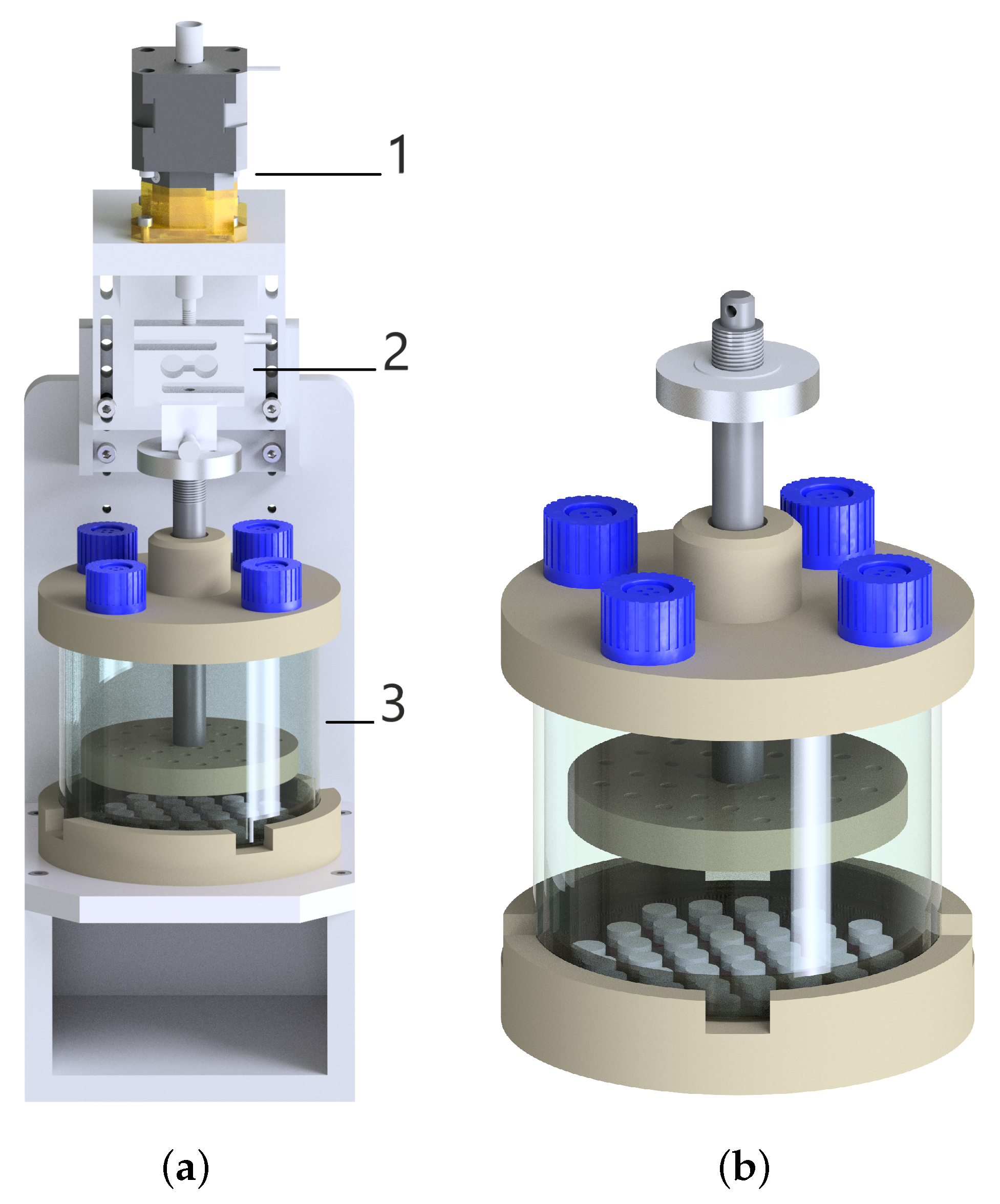
There are four features of the mechanical loading set-up in a bioreactor system: (1) The set-up of actuating and motion-transforming system with good reproducibility, high resolution, and predefined frequency; (2) The maintenance and calibration of the load cell to measure the reaction force; (3) A monitoring and control system that captures the deformation and force data precisely and allows for the change and control of the loading schemes; (4) A chamber for samples should be designed to provide a physiological culture environment for cells and to maintain sterility. Figure 1 represents the schematic image of the bioreactor system with its major components and the cultivation chamber with a cell-seeded collagen matrix.
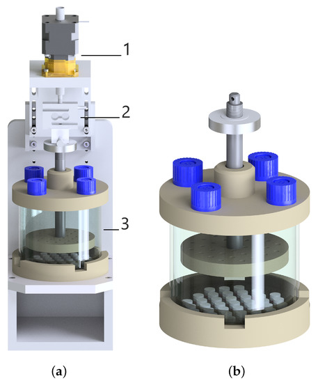
Figure 1.
(a) The technical drawing of the compression bioreactor with its components: linear motor (1), load cell (2), and chamber (3). (b) More focus on the chamber with the petri dish including 37 samples and with the stamp.
The bioreactor components were created in Autodesk Inventor and manufactured firstly as a prototype using a 3D printer. The bioreactor prototype was utilized to test the size of components, the design for the assembly and disassembly. Afterwards, all the components of the bioreactor chamber were produced using medical-grade thermoplastic polyetheretherketone (PEEK), which is an inert and biocompatible material showing excellent mechanical and chemical resistance [12,13]. The main base of the bioreactor to stabilize the entire device was produced with aluminum material. The upper part of the chamber possesses four holes closed with the filter caps of cell culture flasks allowing gas exchange. A custom-made silicone mold is cast using polydimethylsiloxane (PDMS) and placed to the bottom part of the chamber in a sterile Petri dish. The silicone mold includes 37-wells for 3D cell culture, as well as allowing a parallel mechanical stimulation for each sample (see Figure 1). The upper and bottom part of the chamber are connected to each other with a cylindrical glass to ensure a closed, sterile and transparent environment for cell-seeded scaffolds. A stainless-steel flat piston is attached to the load cell, which records the force during mechanical loading. A stamp positioned at the end of the flat piston includes tiny holes to enable medium flow inside them, thereby eliminating the sticking samples on the stamp. The load cell is attached to a linear stepper motor which is placed on the top of the bioreactor.
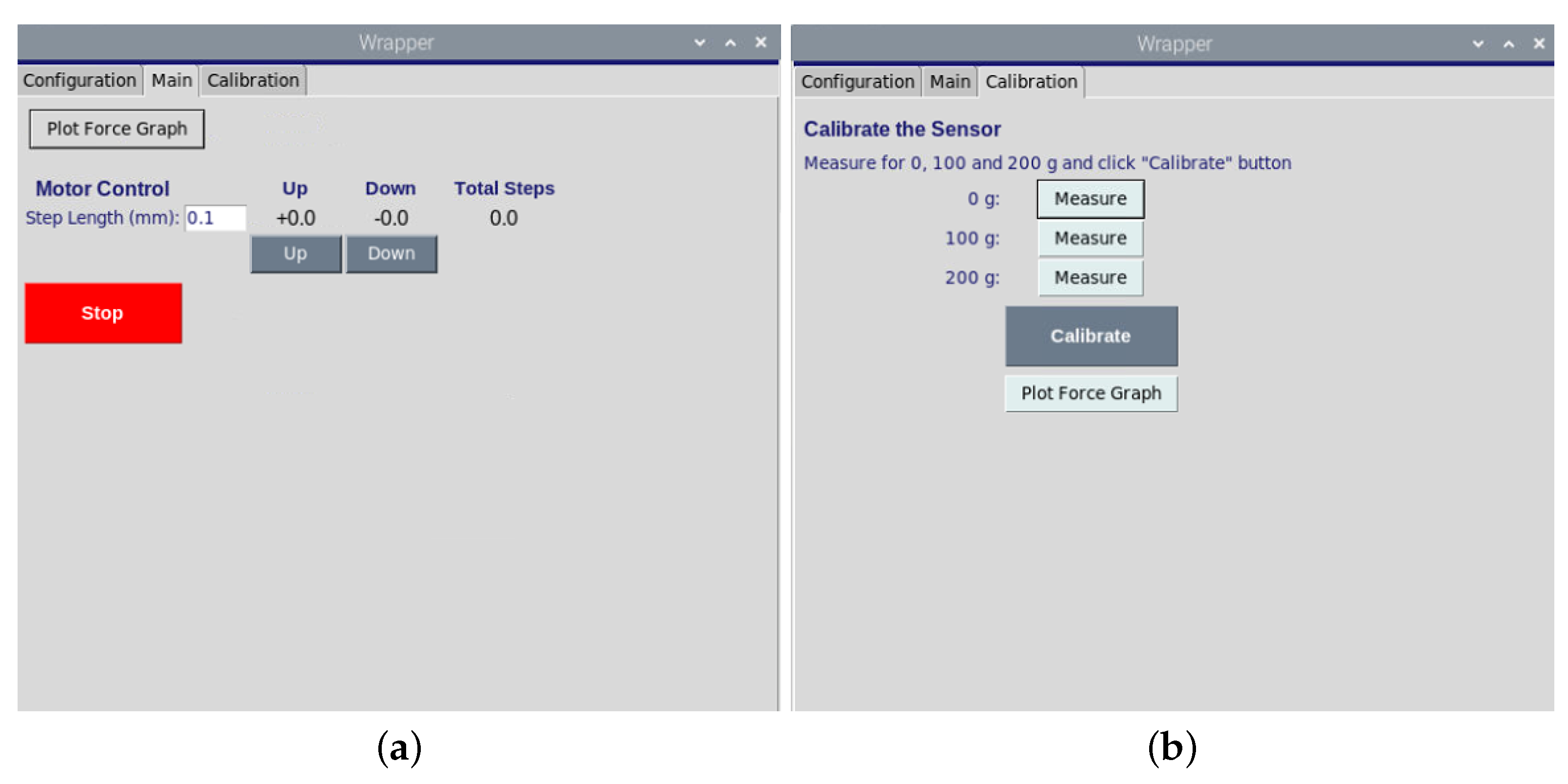
The stepper motor (NEMA, Nanotec, Feldkirchen, Germany) performs a linear motion triggered by the custom-programmed Raspberry Pi which is a low-cost and high-performance microcontroller board. The revolution of the motor is represented by 200 steps, which equal a rotation of 1.8 per step. Here, we applied a micro-stepping control by dividing each full step into smaller steps to help smooth out the motor rotation. The motor speed is controlled by implying a time delay variable between several steps. The stamp can be moved towards samples using the motor up–down component of the software. The measurement of reaction force is important for monitoring pre-stress and to evaluate material stiffness during an experiment. Therefore, the load cells should be well-constructed and calibrated to measure force changes precisely. Here, we used a load cell with a nominal force of 2N (ME Meßsysteme, Hennigsdorf, Germany) which is calibrated using the controlling software. The load cell calibration ensures that the sensor operates an accurate and error-free measurement. After positioning the load cell on the bioreactor and reading the offset value, the known loads are applied to the load cell incrementally, and the output readings are centralized and scaled for each load by the software (see Figure 3). Moreover, the movement of the motor is done without friction since the friction influences the measured force unpredictable.
2.2. Set-Up of the Controlling Software
The desktop software is written in 3.7.0 version of Python [14]. It mainly consists of four interconnected components, namely, motor sequence, wrapper, plotter, and data handler. Each of these components is designed to perform a distinct task. The motor sequence is the main component of the software where the whole processing of the experiment takes place. It works by receiving the parameters of experiments from the wrapper file and then setting up the stepper motor according to these parameters. It consists of three further sub-components which are responsible for finding pre-stress, moving motor down-up and applying motor movements in sine and triangular form during an experiment.
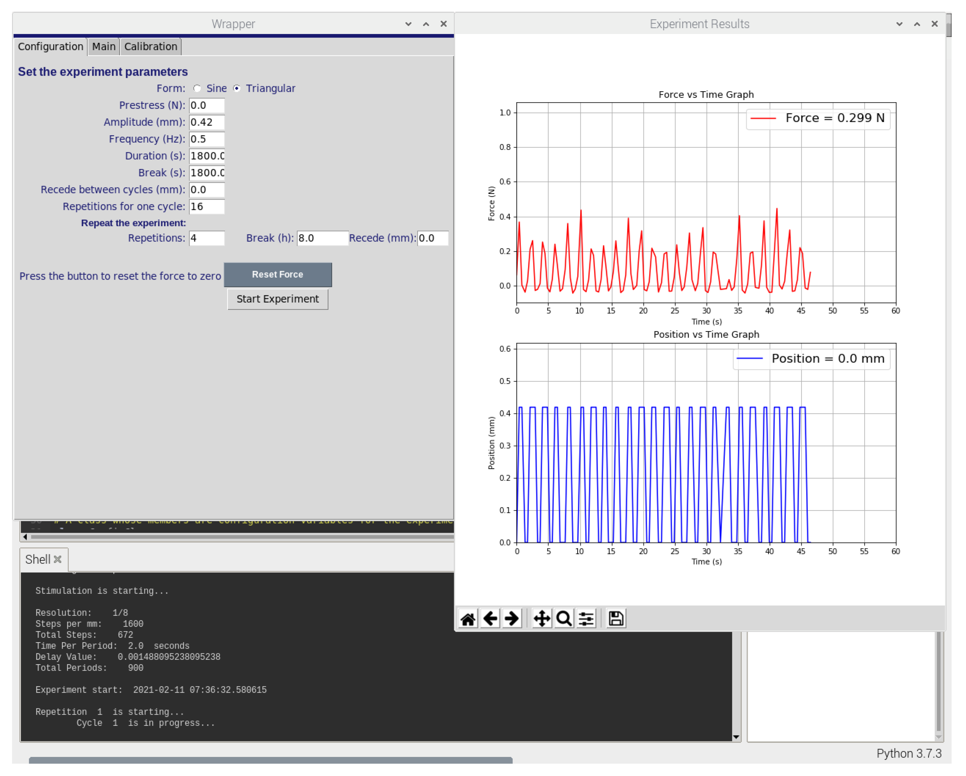
The wrapper component draws the user interface (UI) of the software using the Tkinter package of Python. Figure 2 and Figure 3 display the user interface which can be used to set the experiment parameters, calibrate the force sensor, control the stepper motor and start or stop the experiment. Similarly, the plotter component draws experiment graphs using the Matplotlib package of Python. It collects force data from the force sensor and position data from the stepper motor to plot both against time. It is programmed to do so in real-time and to refresh both graphs after each minute (60 s).
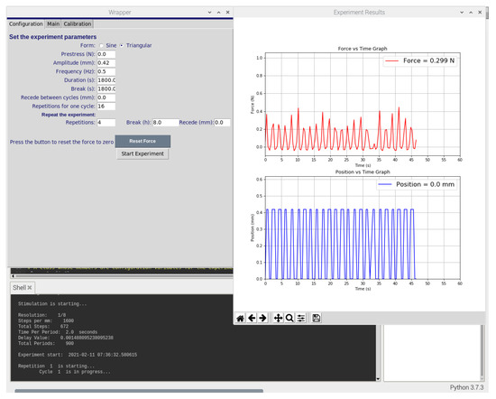
Figure 2.
Screenshot of the software graphical user interface used to control the bioreactor system. The custom-developed software enables the control of actuator position using displacement commands, frequency, time, duration, and repetition of the experiments, as well as providinga graphs of the force and the displacement.
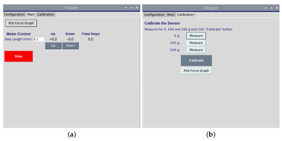
Figure 3.
(a). The graphical user interface of motor movement opposite or toward the samples. (b). The graphical user for the calibration of load sensor.
The data handler component acts as a data transportation bridge between cloud database and python software. At the initialization of the software, it fetches previous experiment parameters from the cloud database and populates them in the user interface. On the contrary, at the start of each experiment, it extracts the experiment parameters from the user interface and sends them to the cloud database. Similarly, during the whole experiment, it stores experiment data i.e., force, position, and time values in a cloud database in real-time.
2.3. Set-Up of the Mobile Application
A custom-built android application was developed to control the bioreactor on a smartphone in real-time. The application consists of multiple screens, where each screen has its own user interface file, called layout. Furthermore, every layout file is linked to a corresponding activity file where its backend functionality is written. The linked activity file is the core of each layout. The source code of the mobile application is written in Java language while layouts are developed in XML language. The application was compiled and tested on an android device with a software development kit (SDK) version 29. However, its application package (APK) is designed to be fully functional on Android devices with a much lower SDK version.
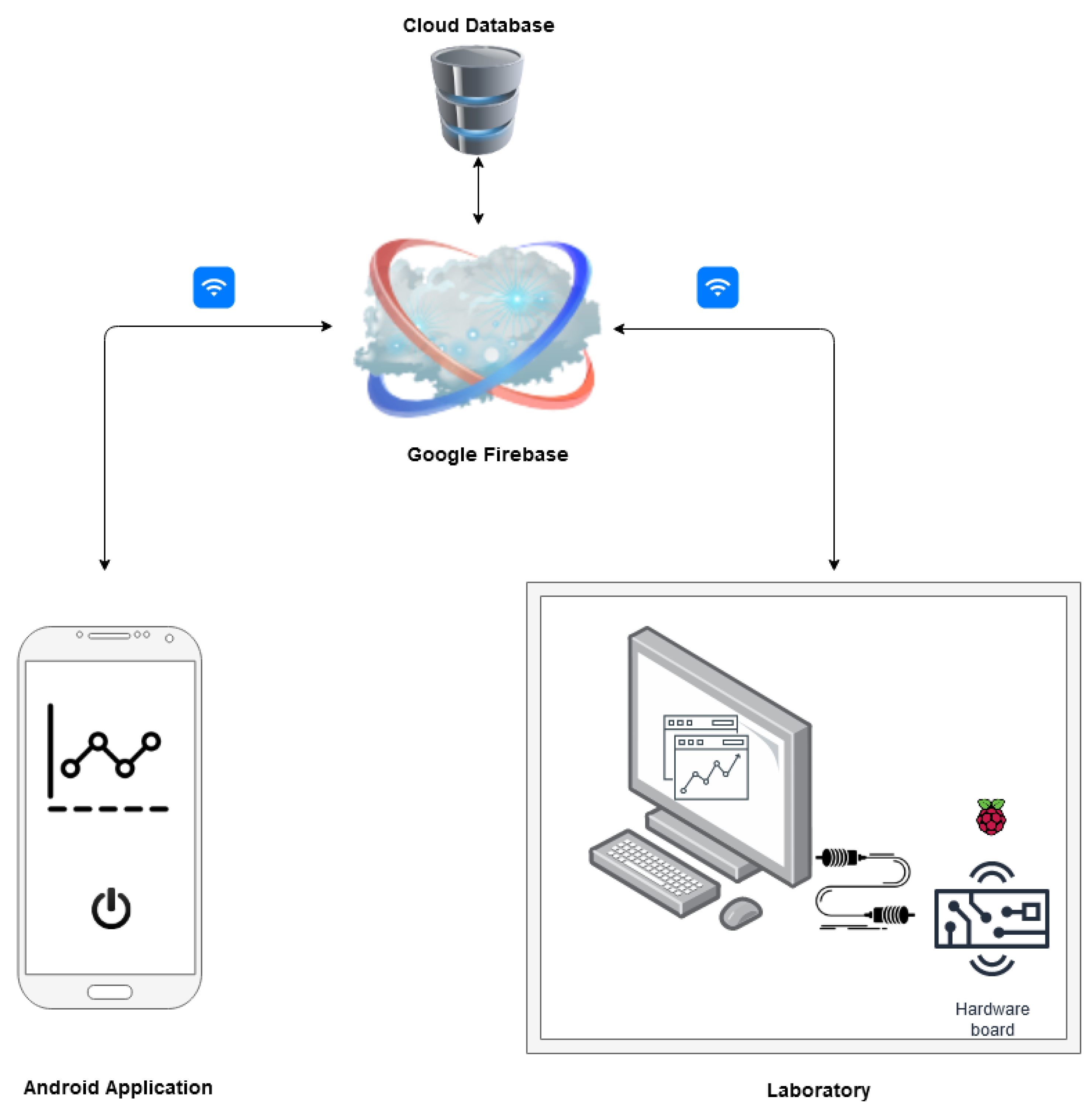
The application is connected with a cloud database which acts as a real-time data communication bridge between Raspberry Pi and the android application (see Figure 4). The database contains the information including login credentials, the status of the bioreactor, experiment parameters and the experiment data. It also stores the data points from previous experiments. The database is hosted by Google Firebase, a cloud-based platform, which guarantees real-time data access. The database uses no SQL and uses JSON format to store data.
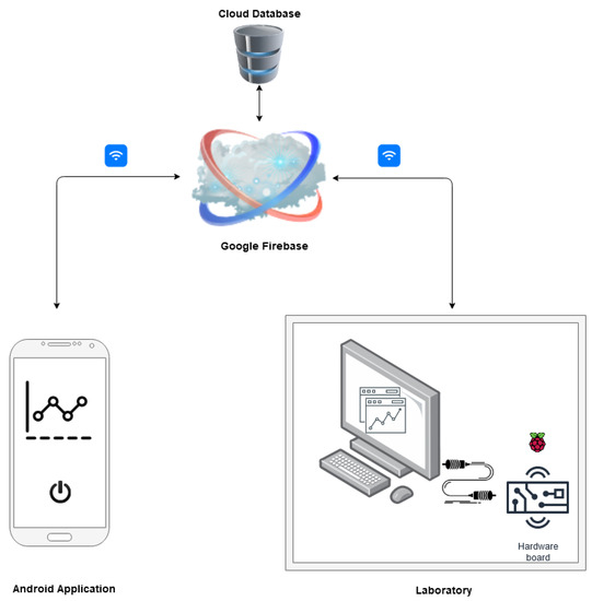
Figure 4.
Overview of the connection between mobile application and controlling software.
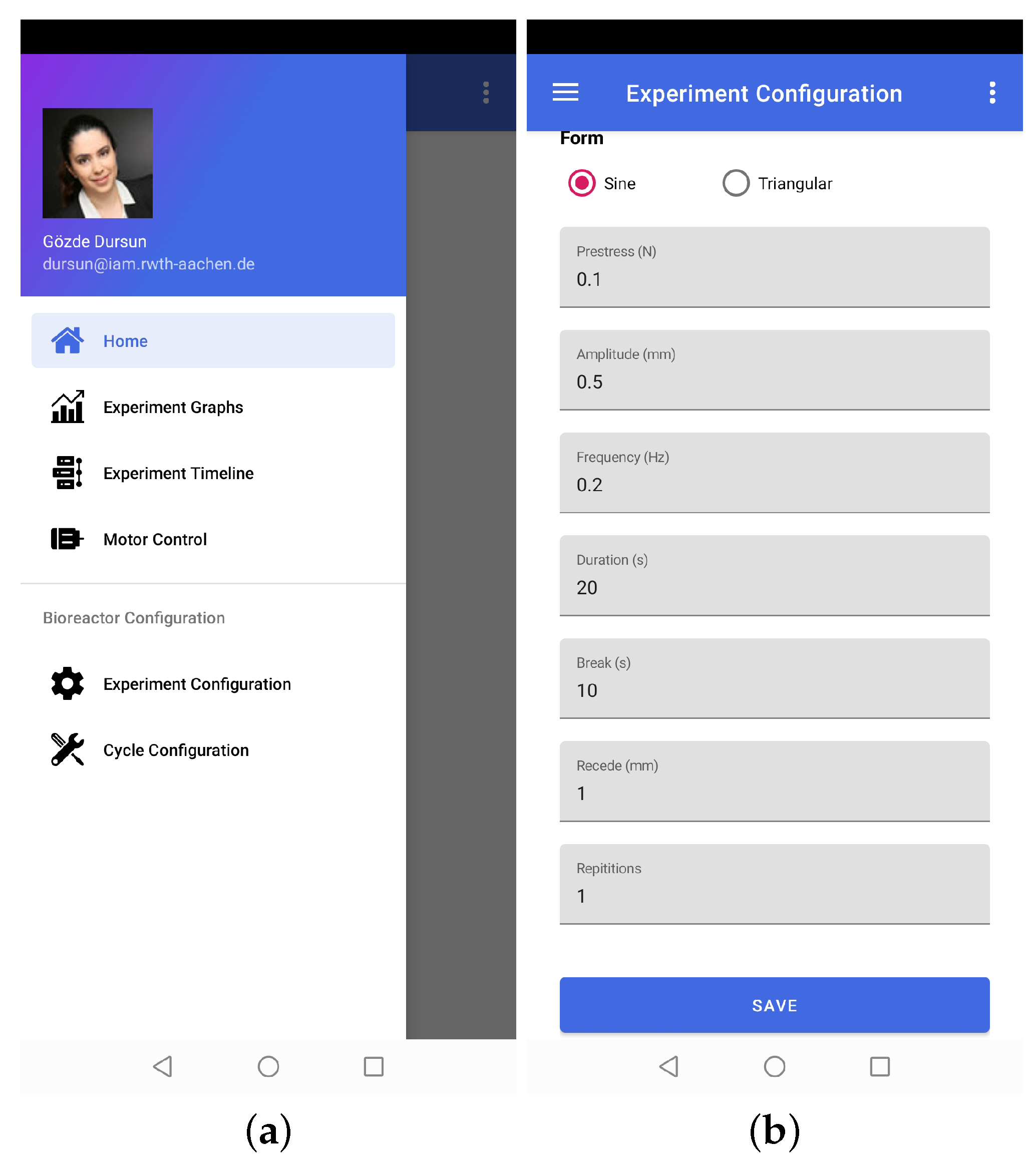
The functionalities of the application can be divided into two broad categories, i.e., experiment control and data visualization. The experiment-control-related functionalities include entering experiment parameters, positioning the stepper motor, starting/closing the experiment, viewing experiment graphs, and checking the status of the bioreactor (see Figure 5). Data visualization functionality refers to retrieving historical experiment data from a cloud database and recreating experiment graphs. That is how the application remotely provides full control of the experiments and bioreactor.
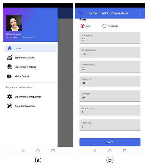
Figure 5.
Representative screenshots of the mobile application. (a). The graphical user interface which shows the main menu of the mobile application. (b). The experiment configuration layer enable to control and change the experiment parameters.
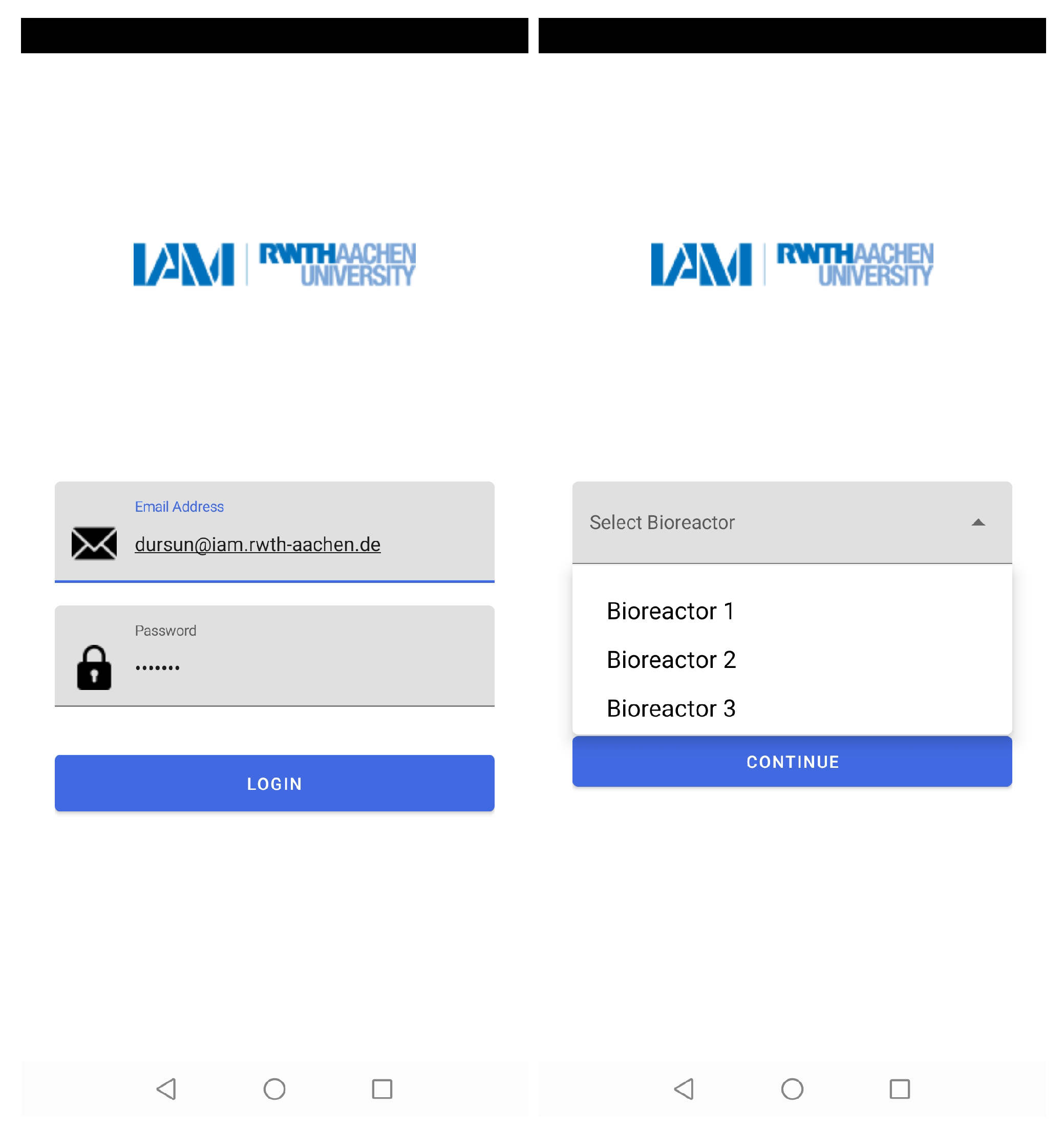
The mobile application authorizes users to access different bioreactors at the same time. Thus, the number of experiments that could be conducted in parallel and real-time data could be assessed by multiple users at their workplace or home (see Figure 6).
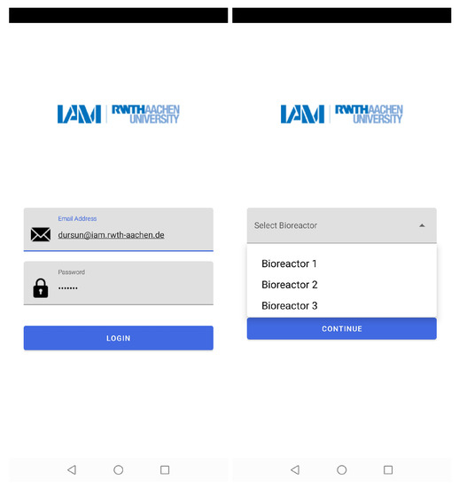
Figure 6.
The layers of the mobile application which show the access of different users by mail addresses and choice of bioreactor with their corresponding numbers.
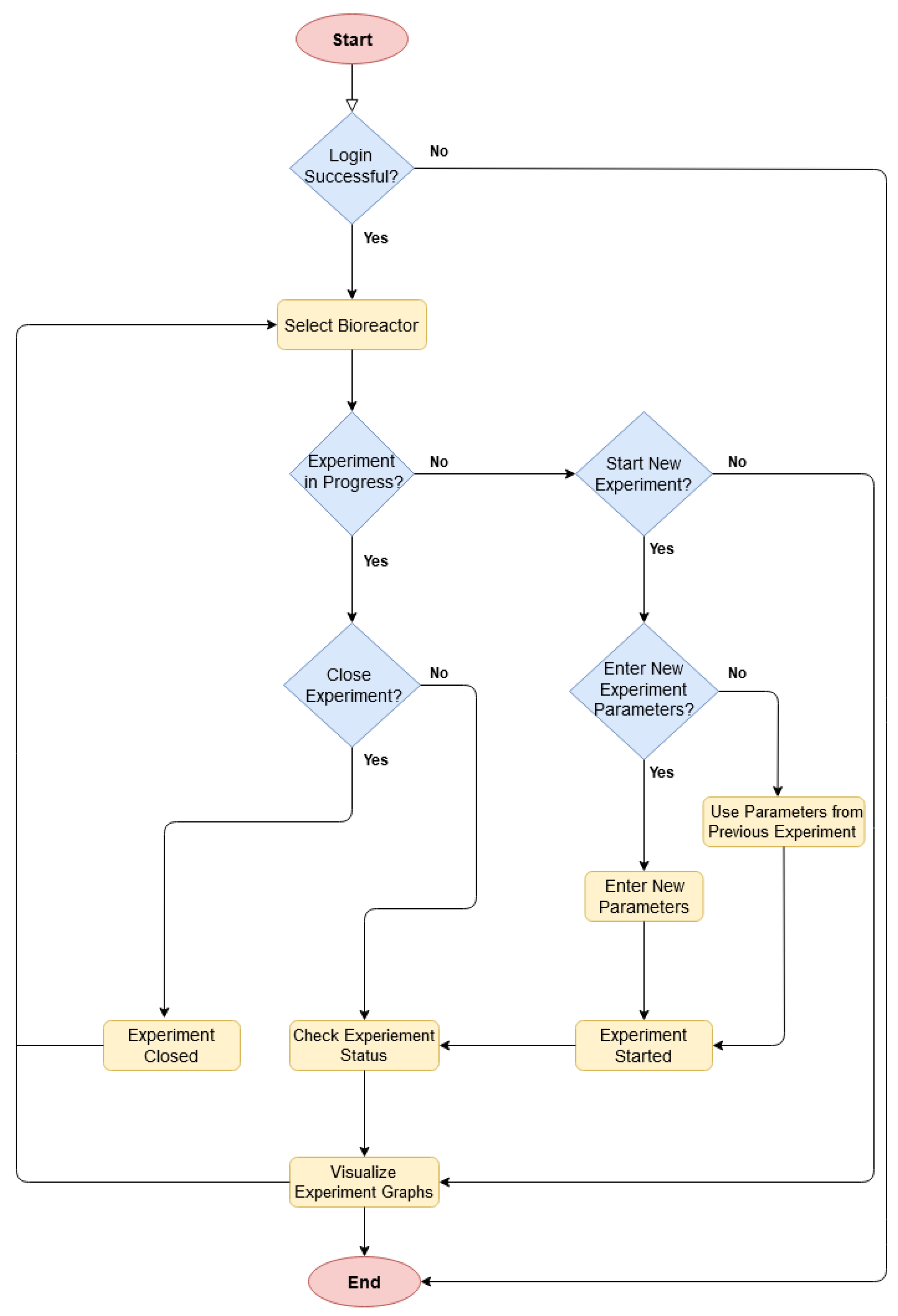
Figure 7 represents the workflow of the mobile application. The application starts with a login page, which is followed by the selection of the desired bioreactor. If an experiment is already in progress on the selected bioreactor, then it shows the current status and relevant data graphs. It also allows the user to close the experiment. Otherwise, if no experiment is running, the user can make a choice to either start a new experiment or to visualize data graphs from the previous experiments. If the user proceeds with a new experiment, then he/she needs to either enter new experiment parameters or reuse them from the previous experiment. Once the experiment is conducted, the user can see the data graphs and current status.
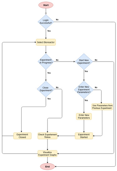
Figure 7.
Source code algorithm of the mobile application.
2.4. Conduction of Three Dimensional Cell Culture Experiments in the Compression Bioreactor
The functionality of the newly designed compression bioreactor is examined with the conduction of cell culture experiments using the 3D in vitro cartilage model. The 3D in vitro tissue model includes two main layers: the first layer mimics the cartilage tissue and the second layer contains a cell-free collagen-I-based implant which is used for the treatment of chondral defects. The first layer is prepared inside the wells of sterile custom-made polydimethylsiloxane (PDMS) mold by mixing human chondrocytes (Promocell, Heidelberg, Germany) in passage three with 100 µL collagen solution of 4 mg/mL ((PureCol EZ gel, Advanced BioMatrix Inc., Troisdorf, Germany). The cell concentration of 100,000 cells/mL is taken for each in vitro 3D tissue model. As a second layer, 3D collagen type-I based cell-free implants (Meidrix Biomaterials GmbH, Esslingen, Germany) are fabricated by mixing an acidic collagen solution of 10 mg/mL and a gel neutralisation solution in a ratio of 4:1. Besides, this collagen mixture is further diluted in a ratio of 3:1 with Dulbecco’s Phosphate Buffered Saline (DPBS, Gibco by ThermoFisher Scientific GmbH, Waltham, MA, USA) The diluted collagen mixture of 8 mg/mL and 6 mg/mL is cast into a cylindrical shape, with an 8 mm diameter and a 4 mm height. Following the gelation process, the implants are brought into contact with the cell-seeded matrix.
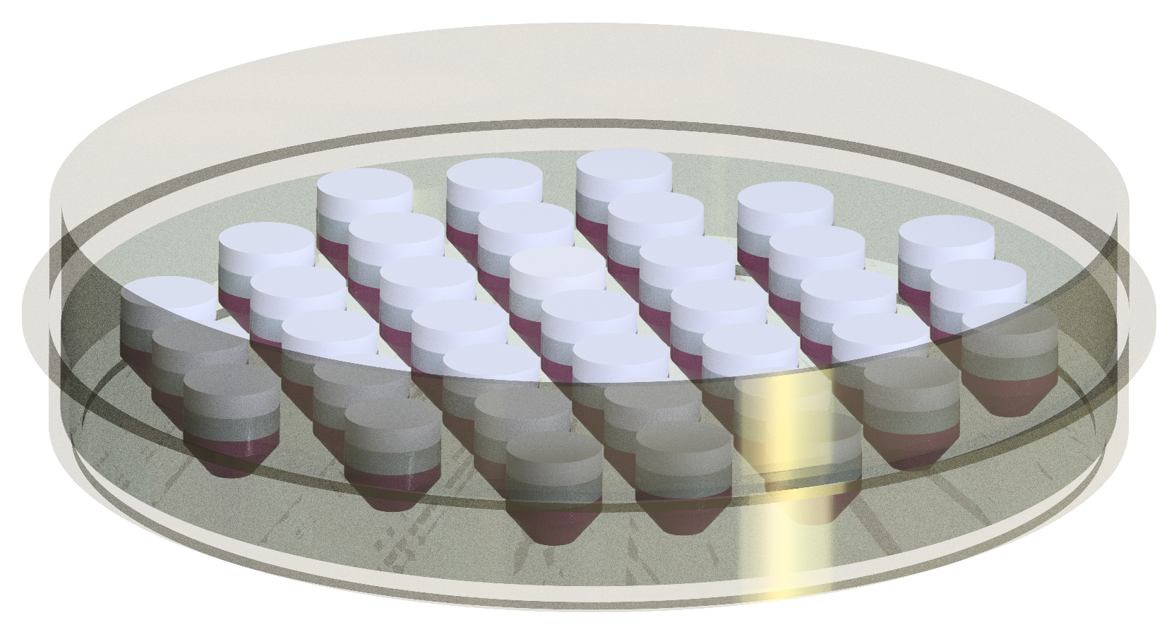
The petri dish seen in Figure 8, including the silicone mold with 3D in vitro tissue models, is put inside the compression bioreactor, which was placed in an incubator with 5% CO at 37 C, while the static culture of the 3D in vitro tissue model was kept only in the incubator. During dynamic and static cultivation, the specimens were fully immersed in a culture medium prepared with Dulbecco’s Modified Eagle Medium/Nutrient Mixture F-12 (DMEM-F12, Gibco by ThermoFisher Scientific GmbH, Waltham, MA, USA) supplemented with 10 % fetal bovine serum (FBS, Gibco by ThermoFisher Scientific GmbH, Waltham, MA, USA), 1% penicillin-streptomycin (Gibco by ThermoFisher Scientific GmbH, Waltham, MA, USA), 1% amphotericin (Gibco by ThermoFisher Scientific GmbH, Waltham, MA, USA). Dynamic cultures were compressed unconfined and displacement-controlled with an initial strain of 15% in a vertical direction and a frequency of 0.5 Hz for 2 weeks. The stimulation was applied as a block of 30 min stimulation and 30 min break in total 16 times on a daily basis, after which a resting period of 8 h was introduced.
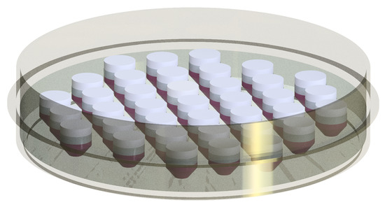
Figure 8.
The technical drawing of the highly customizable PDMS mold placed in a petri dish with 37 in vitro 3D models.
2.5. Determination of Cell Viability and Migration
Cell-free collagen-I based implants were analysed using the Live/Dead cell assay which stains the live cells green and the dead cells red. At the end of the experiment period, specimens were washed in PBS at room temperature, followed by incubation with 5 M Calcein AM (ThermoFisher Scientific, Waltham, MA, USA) for 30 min and 5 M PI (ThermoFisher Scientific, Waltham, MA, USA) for 10 min. Cell distributions inside the cell-free implants were monitored by taking pictures with an inverted fluorescence phase-contrast microscope (Keyence BZ 8100). A z-stack with a thickness of 10 m was collected for each specimen in order to determine the maximal depth of cell migration in the implants. The maximal depth was calculated depending on the number of images in the z-stack. The percentage of the maximal depth in the implant was determined using the corresponding implant height which was measured with a digital calliper after the experiments. The 3D visualization of the cell migration depths was created using Fiji [15] image analyzing program. To determine the migrated cell amount and cell viability, the number of green cells and red cells in the first layer of the cell-free implants were counted using Fiji [15] image analyzing program. The corresponding alive and dead cell numbers were used to calculate the cell viability in percentage.
3. Results and Discussion
In this study, we developed a new bioreactor system which can help to investigate the effect of cyclic homogeneous compression on the cellular processes using our own experience in this field [16,17]. Stoffel et al. [18] have introduced four types of bioreactors that perform physiologically realistic motions to determine the material properties of distinct replacement materials and natural tissues. Further, the tissue compression bioreactor has been used to understand the migration behaviours of chondrocytes [19,20]. This study shows the further development of compression bioreactor in a large volume which provides homogeneous uniaxial compression on the multiple in vitro models at the same time and thereby prevents operator and system dependent variability. Moreover, it is a great advantage that the low-costing controlling system can be easily applied to other mechanical loading system types such as tensile or shear.
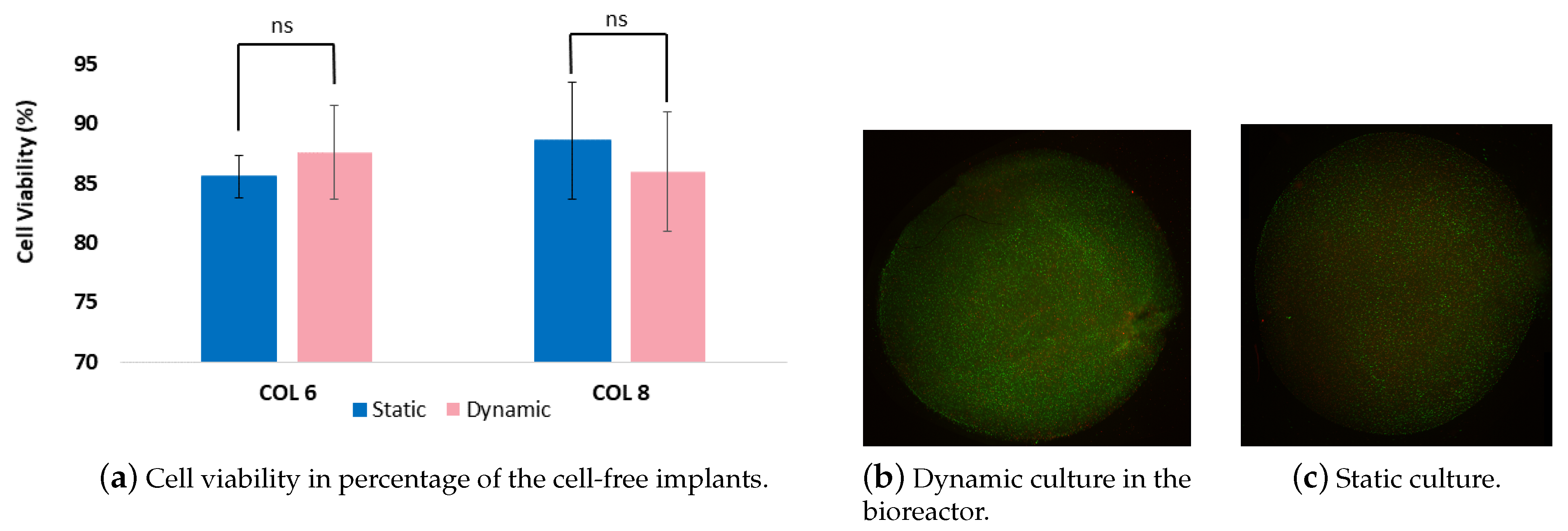
Cultivation chambers provide an appropriate physiological environment for the cell/tissue constructs as well as maintain sterile conditions during the experiment span [21]. This led us to the choice of materials that are biocompatible, suitable for cleaning and sterilizing. Following the long-term dynamic and static experiments, the cell viability in the 3D in vitro cartilage models were determined since it is an indicator of cell health. As it is seen in Figure 9, the cell viability was above 85% for both dynamic and static cultured cell-free implants of the in vitro model. However, there is no significant difference was observed between dynamic and static culture. Our cell viability results indicate that the compression bioreactor system supports the cellular growth in two weeks period and does not cause a significant decrease in viable cell density, which is comparable with the results of Nachtsheim et al. [19]. Nachtsheim et al. have similarly determined a high percentage of chondrocytes viability at minumum of 80% after three weeks of dynamic loading. In addition, Gamez et al. [22] reported higher cell viability in collagen scaffolds by 93.5% upon 24 h loading which is much shorter than our loading regimes. It should be noted that the long-term experiments tend to imply a higher risk of cell apoptosis. Further, we analysed the cell-seeded parts of an in vitro model that were cultured with the cell-free implants conjointly. Although the cell viability percentages were not determined, the pictures displayed in Figure 9 indicate that the intensity of the green color was higher than the red color, meaning that the density of the alive cells was more than the dead cells In addition to cell viability results, there was no contamination detected during the experiments. Our results reveal that the cultivation chamber supports and maintains the cell experiments with the required cultivation parameters for two weeks.
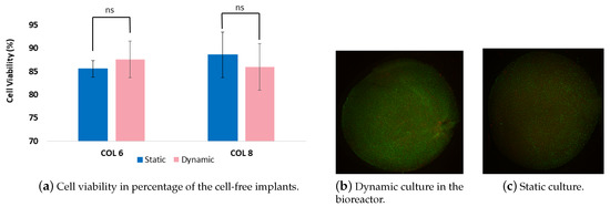
Figure 9.
(a). The graph shows cell viability percentages of cells which migrated from the cell-seeded collagen scaffolds into cell-free collagen-I-based implants. (b,c). Randomly chosen pictures taken from the chondrocyte-seeded collagen matrix were cultured dynamically (b) and statically (c).
Recently, 3D printing techniques have been used for the bioreactor design to fabricate low-cost and customizable systems [23,24]. Here, Here, a silicone mold for the cultivation of the 3D in vitro models was produced with a negative form which was developed using 3D printing technology. This method enables us to design highly customizable silicone molds, and thereby investigate different implants in distinct sizes and shapes. Moreover, the culture well-based structure of the molds allowed for the cultivation of 37 separate in vitro models (see Figure 8) The customizable structure of these silicone molds holds an advantage for the examination of different adjustment of cell concentration and cell types. Further, collagen material is used in this study to create the in vitro model due to our research interest. However, it should be noted that the developed bioreactor system is compatible with different tissue engineering scaffolds such as alginate, chitosan, and elastin. Furthermore, the bioreactor prototypes manufactured using 3D printer enable simplicity in the design of bioreactors, where the bioreactor can be easily assembled and disassembled. This ensures that the contamination risk in the cultivation chamber is minimized since the sampling and maintenance of the in vitro models can be performed in the short term out of incubator.
One of the interests in this work is the accurate control and monitoring of the stimulation parameters due to time and amplitude by the implementation of a simple and low-cost controlling unit. Our Python-based controlling software provides real-time information including the time, the reaction force and the displacement. The measured data can be stored either on Raspberry Pi as a plain text file or on the cloud as JSON file, and can be plotted easily as seen in Figure 10.

Figure 10.
The force-displacement diagram for the first six minutes of 30 min experiment cycle.
Hydrogels are of great interest as biomaterials in tissue engineering since their composition and mechanical properties are similar to biological tissues [25]. They are mechanically characterized as viscoelastic materials, which exhibit an elastic behaviour conferred by a solid network surrounded by an aqueous solution, which is associated with their viscous behaviour [26]. Figure 10 depicts the viscoelastic behavior of the material under consideration. During cyclic compression performed on in vitro cartilage models, the initial deformation generates a high peak stress at the beginning of the compression test, which leads to the diffusion of water through the material pores. This is followed by the most substantial decrease in the reaction force, called stress relaxation. After the stress relaxation phase seen at the beginning of the experiment, where the reaction force varies between 0 and , this force approaches a stage that varies between the two fixed values of around and . Due to the culture medium in which the in vitro cartilage models are immersed, the stamp produces a slight tension when it is removed from the specimen. This may lead to this force variation.
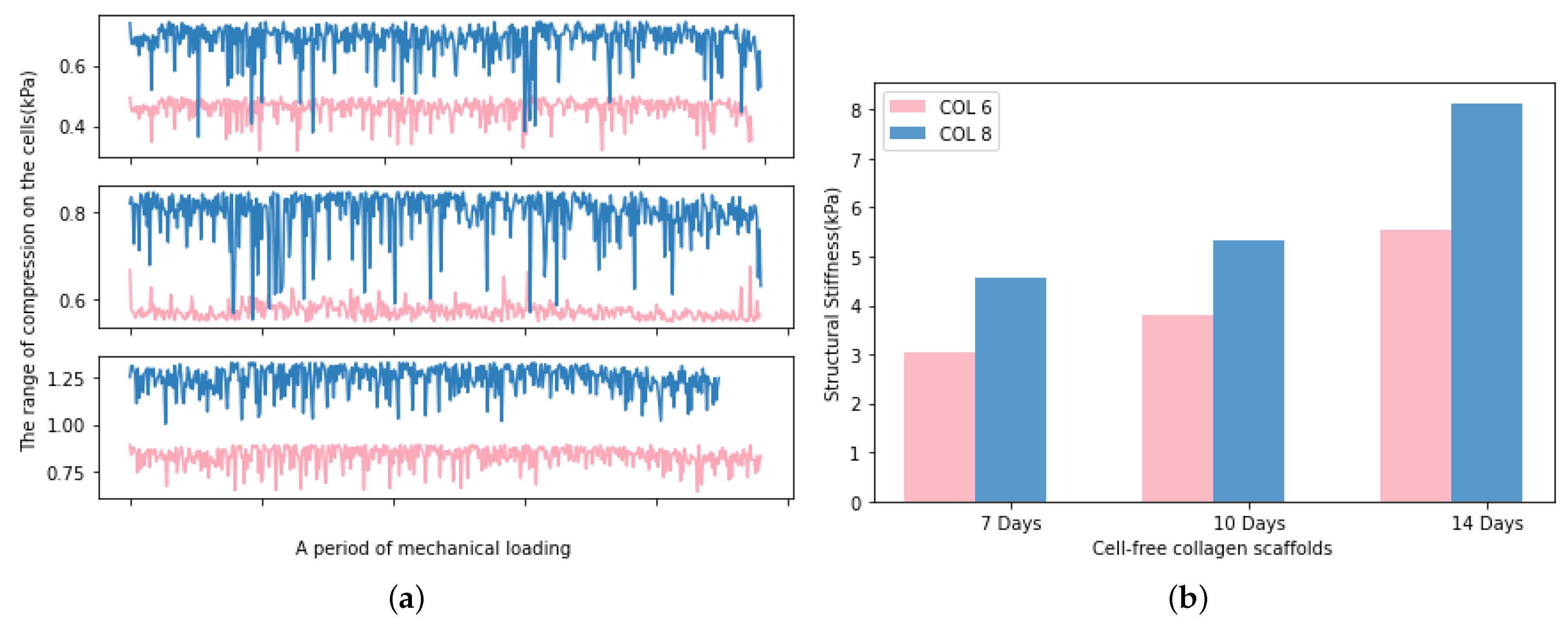
The real-time monitoring of the mechanical stimulation has a clear advantage over endpoint testing, which is the possibility to make adjustments to bioreactor conditions in response to changes in implant structural stiffness [27]. In this study, the developed software enables the monitoring of the real-time compression range on the samples, and the structural stiffness can be calculated from the extracted data of force and displacement. As presented in Figure 11a, the average compressive modulus of the samples is increasing with the cultivation time. The limitation of these measurements is the impossibility of diameter measurement during mechanical loading since the implants were located in a cultivation chamber. Therefore, the diameter is kept as a constant value in the calculation of structural stiffness. Figure 11b indicates the increased structural stiffness of the implants during the mechanical loading. This can be explained by the cell colonisation into the implants. However, we need to take into consideration that the height of the implant reduces during the mechanical stimulation period and the water concentration of implants decreases because of the compression. These facts led to the determination of a slight increment in the compressive modulus of COL-6 and COL-8 implants in respect to cultivation time.
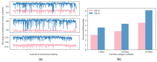
Figure 11.
(a). The average compression values determined in the cells, the upper subgraph displays the first 7 days, the middle one displays 10 days and the bottom one displays the 14 days. (b). The average structural stiffness of COL-6 and COL-8 implants during 7 days, 10 days, and 14 days, respectively.
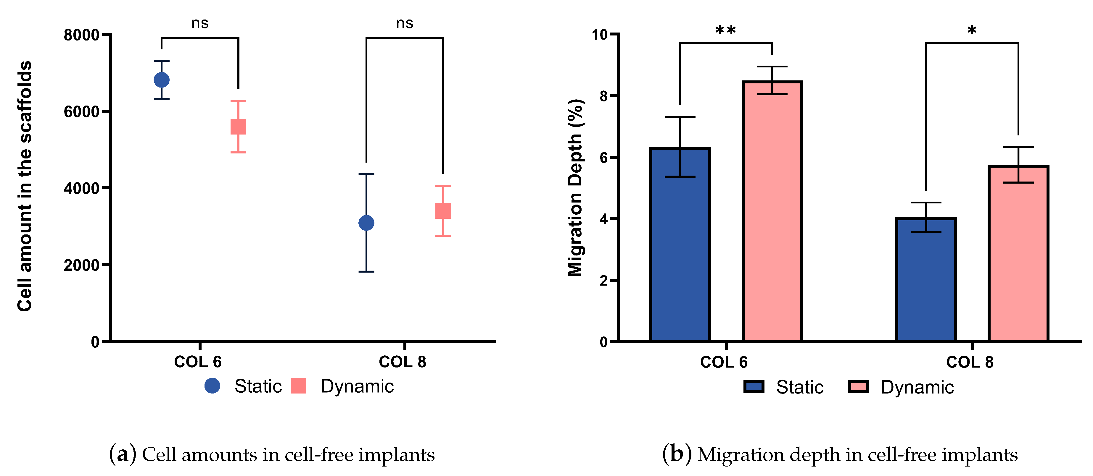
The compression bioreactor system is also very effective in supporting the cell migration process into cell-free collagen-I-based implants. The graph represented in Figure 12a shows the number of cells located on the outer surface of cell-free implants. There are no statistical difference in the cell amounts between COL-6 and COL-8, as well as dynamically and statically cultured in vitro models. In parallel, the migration depth graph represented in Figure 12b indicates that the cell migration depth was higher in the dynamically cultured COL-6 and COL-8 implants than statically cultured samples. This proves that the dynamic culture of in vitro models in the compression bioreactor system promotes active cell migration from the cell-seeded collagen matrix into the different concentrations of cell-free collagen-I-based implants, COL-6 and COL-8. Furthermore, it should be emphasized that the COL-6 implants may possess larger pore sizes inside the material in comparison to the COL-8 implants since the lower collagen fiber concentration of COL-6 implants is lower and thereby water content is higher. This may lead to a faster cell migration inside COL-6 implants, as well as a difference in the structural stiffness of the implants represented in Figure 11b. The higher structural stiffness of COL8 can be explained by its more densely packed collagen fibers due to its higher collagen and lower water concentration. The variation in cell migration between COL-6 and COL-8 implants, statically and dynamically cultured, may correlate with the pore size and structural stiffness of implants since cellular and tissue functions are modulated by the physical properties of the substrate.
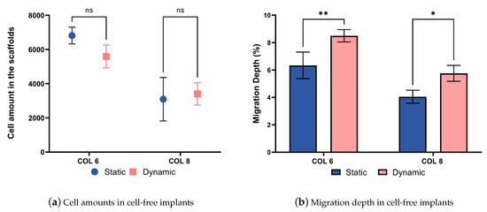
Figure 12.
(a). Alive cell amounts migrated from the cell-seeded collagen construct to the COL-6 and COL-8 implants. (b). The migration depth in percentages between the static and dynamic culture of COL-6 and COL-8 implants. statistically difference.*: p ≤ 0.05; **: p≤ 0.01.
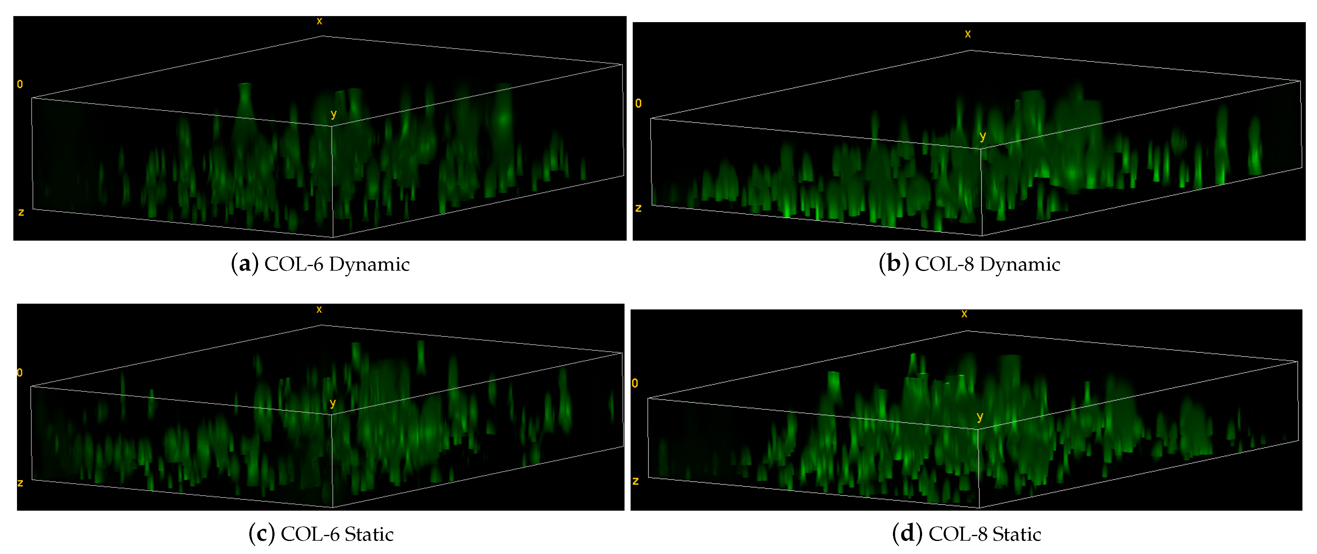
The cell migration is further confirmed by the 3D images which indicate local cell migration inside the cell-free implants for the dynamic and static culture of COL-6 and COL-8 implants (see Figure 13). The migration direction is from the bottom to the upper part of implants. As seen in the 3D images, there are more cells located in the bottom part, where the cell-seeded collagen matrix is cultivated adjacently to the implants. These data prove that COL-6 and COL-8 implants support cell viability and migration. It should be also noted that cell migration occurs more actively in the dynamic cultures, although there is no significant difference between cell amounts between dynamic and static cultures.
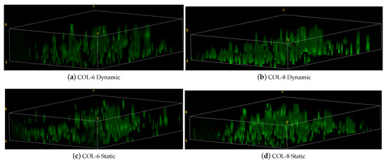
Figure 13.
Representative 3D images of z-stacks in the static and dynamic culture of COL-6 and COL-8 implants.
4. Conclusions
Here, we have developed a compression bioreactor that is highly simple and customizable to construct in a cost-effective manner. The in-house software of the bioreactor provides an opportunity for faster implementation of desirable changes to the controlling unit, as well as transmits instant experimental data to the cloud. The bioreactor mobile application enables users to display and control the experiment information remotely through smartphones. A practical cleaning and sterilization of the bioreactor compartments minimize the contamination risk and provide a user-friendly functionality. Our experiment results have ensured that this is a compatible system for performing long-term cell culture experiments with minimal maintenance and high cellular activity. The cells seeded in a collagen scaffold and cultured in a dynamic setting showed improved cell activities by deeper colonisation inside the cell-free collagen-I-based implants. This study proves that the unique design of the compression bioreactor is a powerful and real-time controllable tool for mechanobiology studies. Since the cartilage tissue is under compression and shear loading in its natural environment, future work will aim to implement shear forces in the bioreactor design.
Author Contributions
Conceptualization, G.D.; Formal analysis, B.M. and M.S.; Funding acquisition, G.D. and M.S.; Investigation, G.D.; Methodology, G.D.; Project administration, G.D. and M.S.; Resources, B.M.; Software, M.U.; Supervision, M.S.; Visualization, G.D., M.U. and B.M.; Writing—original draft, G.D.; Writing—review & editing, M.S. All authors have read and agreed to the published version of the manuscript.
Funding
This research was funded by the Excellence Initiative of the German federal and state governments.
Acknowledgments
We would like to thank the Department of Anatomy and Cell Biology, Uniklinik RWTH Aachen University for their contribution by providing us an access to their confocal fluorescence microscope.
Conflicts of Interest
The authors declare no conflict of interest.
References
- Caddeo, S.; Boffito, M.; Sartori, S. Tissue engineering approaches in the design of healthy and pathological in vitro tissue models. Front. Bioeng. Biotechnol. 2017, 5, 40. [Google Scholar] [CrossRef] [PubMed]
- Obregón, R.; Ramón-Azcón, J.; Ahadian, S. Bioreactors in tissue engineering. Tissue Eng. Artif. Organs Regen. Med. Smart Diagn. Pers. Med. 2017, 1, 169–213. [Google Scholar]
- Zhao, J.; Griffin, M.; Cai, J.; Li, S.; Bulter, P.E.; Kalaskar, D.M. Bioreactors for tissue engineering: An update. Biochem. Eng. J. 2016, 109, 268–281. [Google Scholar] [CrossRef]
- Fu, L.; Li, P.; Li, H.; Gao, C.; Yang, Z.; Zhao, T.; Chen, W.; Liao, Z.; Peng, Y.; Cao, F.; et al. The Application of Bioreactors for Cartilage Tissue Engineering: Advances, Limitations, and Future Perspectives. Stem Cells Int. 2021, 2021, 6621806. [Google Scholar] [CrossRef]
- Bilgen, B.; Chu, D.; Stefani, R.; Aaron, R.K. Design of a biaxial mechanical loading bioreactor for tissue engineering. J. Vis. Exp. 2013, 74, e50387. [Google Scholar] [CrossRef]
- Hoffmann, W.; Feliciano, S.; Martin, I.; de Wild, M.; Wendt, D. Novel perfused compression bioreactor system as an in vitro model to investigate fracture healing. Front. Bioeng. Biotechnol. 2015, 3, 10. [Google Scholar] [CrossRef]
- Orr, D.E.; Burg, K.J. Design of a modular bioreactor to incorporate both perfusion flow and hydrostatic compression for tissue engineering applications. Ann. Biomed. Eng. 2008, 36, 1228. [Google Scholar] [CrossRef]
- Subramanian, G.; Elsaadany, M.; Bialorucki, C.; Yildirim-Ayan, E. Creating homogenous strain distribution within 3D cell-encapsulated constructs using a simple and cost-effective uniaxial tensile bioreactor: Design and validation study. Biotechnol. Bioeng. 2017, 114, 1878–1887. [Google Scholar] [CrossRef]
- Meinert, C.; Schrobback, K.; Hutmacher, D.W.; Klein, T.J. A novel bioreactor system for biaxial mechanical loading enhances the properties of tissue-engineered human cartilage. Sci. Rep. 2017, 7, 1–14. [Google Scholar] [CrossRef]
- Theodoropoulos, J.S.; DeCroos, A.J.; Petrera, M.; Park, S.; Kandel, R.A. Mechanical stimulation enhances integration in an in vitro model of cartilage repair. Knee Surg. Sport. Traumatol. Arthrosc. 2016, 24, 2055–2064. [Google Scholar] [CrossRef] [PubMed]
- Gemmiti, C.V.; Guldberg, R.E. Shear stress magnitude and duration modulates matrix composition and tensile mechanical properties in engineered cartilaginous tissue. Biotechnol. Bioeng. 2009, 104, 809–820. [Google Scholar] [CrossRef]
- Savaris, M.; Carvalho, G.A.; Falavigna, A.; Santos, V.d.; Brandalise, R.N. Chemical and thermal evaluation of commercial and medical Grade PEEK sterilization by Ethylene oxide. Mater. Res. 2016, 19, 807–811. [Google Scholar] [CrossRef]
- Kumar, A.; Yap, W.T.; Foo, S.L.; Lee, T.K. Effects of sterilization cycles on PEEK for medical device application. Bioengineering 2018, 5, 18. [Google Scholar] [CrossRef] [PubMed]
- Van Rossum, G.; Drake, F.L. Python 3 Reference Manual; CreateSpace: Scotts Valley, CA, USA, 2009. [Google Scholar]
- Schindelin, J.; Arganda-Carreras, I.; Frise, E.; Kaynig, V.; Longair, M.; Pietzsch, T.; Preibisch, S.; Rueden, C.; Saalfeld, S.; Schmid, B.; et al. Fiji: An open-source platform for biological-image analysis. Nat. Methods 2012, 9, 676–682. [Google Scholar] [CrossRef]
- Stoffel, M.; Yi, J.H.; Weichert, D.; Zhou, B.; Nebelung, S.; Müller-Rath, R.; Gavenis, K. Bioreactor cultivation and remodelling simulation for cartilage replacement material. Med. Eng. Phys. 2012, 34, 56–63. [Google Scholar] [CrossRef]
- Nebelung, S.; Gavenis, K.; Rath, B.; Tingart, M.; Ladenburger, A.; Stoffel, M.; Zhou, B.; Mueller-Rath, R. Continuous cyclic compressive loading modulates biological and mechanical properties of collagen hydrogels seeded with human chondrocytes. Biorheology 2011, 48, 247–261. [Google Scholar] [CrossRef] [PubMed]
- Stoffel, M.; Willenberg, W.; Azarnoosh, M.; Fuhrmann-Nelles, N.; Zhou, B.; Markert, B. Towards bioreactor development with physiological motion control and its applications. Med. Eng. Phys. 2017, 39, 106–112. [Google Scholar] [CrossRef] [PubMed]
- Nachtsheim, J.; Dursun, G.; Markert, B.; Stoffel, M. Chondrocyte migration in an acellular tissue-engineered cartilage substitute. PAMM 2018, 18, e201800425. [Google Scholar] [CrossRef]
- Dursun, G.; Markert, B.; Stoffel, M. Experimental Study on Cell-free Approach for Articular Cartilage Treatment. Curr. Dir. Biomed. Eng. 2019, 5, 171–174. [Google Scholar] [CrossRef]
- Lei, Y.; Ferdous, Z. Design considerations and challenges for mechanical stretch bioreactors in tissue engineering. Biotechnol. Prog. 2016, 32, 543–553. [Google Scholar] [CrossRef]
- Gamez, C.; Schneider-Wald, B.; Schuette, A.; Mack, M.; Hauk, L.; Khan, A.U.M.; Gretz, N.; Stoffel, M.; Bieback, K.; Schwarz, M.L. Bioreactor for mobilization of mesenchymal stem/stromal cells into scaffolds under mechanical stimulation: Preliminary results. PLoS ONE 2020, 15, e0227553. [Google Scholar] [CrossRef]
- Raveling, A.R.; Theodossiou, S.K.; Schiele, N.R. A 3D printed mechanical bioreactor for investigating mechanobiology and soft tissue mechanics. MethodsX 2018, 5, 924–932. [Google Scholar] [CrossRef] [PubMed]
- Banik, B.L.; Brown, J.L. 3D-printed bioreactor enhances potential for tendon tissue engineering. Regen. Eng. Transl. Med. 2020, 6, 419–428. [Google Scholar] [CrossRef]
- Hoffman, A.S. Hydrogels for biomedical applications. Adv. Drug Deliv. Rev. 2012, 64, 18–23. [Google Scholar] [CrossRef]
- Cacopardo, L.; Guazzelli, N.; Nossa, R.; Mattei, G.; Ahluwalia, A. Engineering hydrogel viscoelasticity. J. Mech. Behav. Biomed. Mater. 2019, 89, 162–167. [Google Scholar] [CrossRef] [PubMed]
- Popp, J.R.; Roberts, J.J.; Gallagher, D.V.; Anseth, K.S.; Bryant, S.J.; Quinn, T.P. An instrumented bioreactor for mechanical stimulation and real-time, nondestructive evaluation of engineered cartilage tissue. J. Med. Devices 2012, 6, 21006. [Google Scholar] [CrossRef]
Publisher’s Note: MDPI stays neutral with regard to jurisdictional claims in published maps and institutional affiliations. |
© 2021 by the authors. Licensee MDPI, Basel, Switzerland. This article is an open access article distributed under the terms and conditions of the Creative Commons Attribution (CC BY) license (https://creativecommons.org/licenses/by/4.0/).

