Article

Effect of a Baffle on Bubble Distribution in a Bubbling Fluidized Bed

1
Institute for Chemicals and Fuels from Alternative Resources, Department of Chemical and Biochemical Engineering, Western University, Ilderton, ON NOM 2A0, Canada
2
Department of Chemical Engineering and Technology, Tianjin University, Tianjin 300072, China
3
Department of Mechanical and Material Engineering, Western University, London, ON N6A 3K7, Canada
*
Authors to whom correspondence should be addressed.
Processes 2021, 9(7), 1150; https://doi.org/10.3390/pr9071150
Submission received: 20 May 2021 / Revised: 22 June 2021 / Accepted: 29 June 2021 / Published: 30 June 2021
(This article belongs to the Section Energy Systems)

Abstract

:
In this study, the multi-phase Eulerian–Eulerian two-fluid method (TFM) coupled with the kinetic theory of granular flow (KTGF) was used to investigate the hydrodynamics of particle flows (Geldart Group B) in a lab-scale bubbling fluidized bed. The goal was to improve the bubble flow behavior inside the fluidized bed to improve the distribution of an injected liquid, by increasing the flow of bubbles entering the spray jet cavity and, thus, reduce the formation of wet agglomerates. The effects of a baffle on both the injection level and the whole fluidized bed were studied. Different baffle geometries were also investigated. Adding a fluxtube to a baffle can improve the bubble flows and a long fluxtube works best at redirecting gas bubbles. Baffles tend to smooth out variations in the gas distribution caused by the non-uniform inlet gas distribution. A gas pocket appears under all the baffles.

1. Introduction

Fluidization is a process that allows solid particles to be handled like a fluid [1]. Gas–solid fluidized beds are widely applied in chemical and process industries, such as the synthesis of fuels and chemicals, gasification of coal or biomass, and combustion [2,3,4]. Fluidized beds are also used for drying, coating, and granulation in pharmaceutical and food processes [2,5]. A fluidized bed is characterized by vigorous mixing of gas and solids, uniform temperature, controllable handling of solids, and excellent mass and heat transfer. Nevertheless, the complexity of the gas–solid flow structure has been challenging to the researchers and led to numerous studies of the gas–solid hydrodynamics.
Inserting baffles is one of the main methods applied in fluidized bed to modify gas solid dynamic. Baffles can reduce solids bypassing in circulating fluidized beds [6,7], limit the gas backmixing [8,9], and improve the mixing of particles in a certain direction [10,11,12,13,14]. Horizontal baffles can provide staging for solids mixing [8]. As for the fluidized bed with liquid injection, baffles have shown a positive advantage on improving the distribution of injected liquid on fluidized particles and the performance of strippers [15,16,17,18]. Baffles can also improve the distribution of the injected feedstock and reduce gas bypassing in risers [19,20], and enhance gas–solid mass transfer by breaking gas bubbles. Besides, baffles can also be used to promote particle segregation [9,21,22,23].
A typical industrial application of baffles is in the Fluid CokingTM process and its variant, FlexicokingTM, which upgrade heavy oils to lighter products. In the Fluid CokingTM process, heavy oil is sprayed with atomization steam into a bubbling fluidized bed with hot coke particles. Hot coke conveyed from a burner vessel provides the heat required for the thermal cracking and evaporation of hydrocarbons in the reactor vessel [24,25,26]. Imperfect dispersion of the sprayed liquid on the fluidized particles leads to the formation of wet agglomerates that decrease heat and mass transfer rates, thereby causing operating problems, especially in the stripper section where hydrocarbons vapors are removed from the coke particles just before they exit the reactor vessel [27,28,29]. A significant proportion of the injected liquid can be trapped in agglomerates that rapidly bypass the reaction section and contact the stripper sheds, causing their accelerated fouling [27,28,29]. This bypassing can be significantly reduced by using baffles [7,30]. Sanchez et al. [31] used radioactive particle tracking to study the effects of internal baffles in the stripping section of the Fluid CokingTM, and discovered that using a baffle can increase the time that wet agglomerates spend above the baffle and reduce fouling on the sheds of the stripper section. Some studies also suggested that baffles can be used to modify the bubble distribution in the spray region to improve the liquid distribution on the particles in order to reduce the agglomerate formation [15,32].
However, experimental methods always faced the high-cost problems. Numerical modelling of multiphase flows in a fluidization process has snowballed in recent years with the rapid development of computer technology. Different numerical methods have been applied to study the effect of inserting baffle on the fluidized bed performance [10,33,34,35,36]. There are two basic numerical approaches: Eulerian–Eulerian (EE) and Eulerian–Lagrangian (EL). The EE approach has been used to simulate the bubble dynamic in the bubbling fluidized bed systems [37,38,39,40,41]. Compared to the EL method, the EE approach costs less in computational time and resource, which is the main reason that makes it more favorable for the simulation of large-scale fluidized bed. Li et al. [42] simulated the cold model of Fluid CokingTM unit by a multi-Eulerian–Eulerian method. Both FCC and coke particles were used to study the hydrodynamics. The reactor section was designed to be both geometrically and dynamically similar to the commercial Fluid CokingTM unit. The radial voidage profiles were compared with the experimental data. Besides, single gas jet and multi gas jets in a bubbling fluidized bed were also simulated by the Eulerian–Eulerian method in a three-dimensional fluidized bed. Moreover, the jet penetrations as well as the interactions between the jet and the surrounding gas, solids, bubbles, and other jets were investigated [43,44]. The chemical stripping process in a fluid catalytic cracking stripper were also investigated by the Eulerian–Eulerian two-fluid model coupled with modified drag model [45]. Benzarti et al. [46] found out that both types of baffles (circular and trapezoidal) can improve the solid mixing in the Circulating Fluidized Bed by the Eulerian–Eulerian method. However, to the best of our knowledge, there are still not enough studies of baffled bubbling fluidized bed, especially to explore a baffle with fluxtube.
The aim of this paper was to study the impact of a baffle on the bubble flow patterns in a 2D fluidized bed. The main goal was to optimize the novel baffle with fluxtube to maximize its function on modifying the gas bubble distribution and then applying the results in the Fluid CokingTM process to reduce the wet agglomerates.

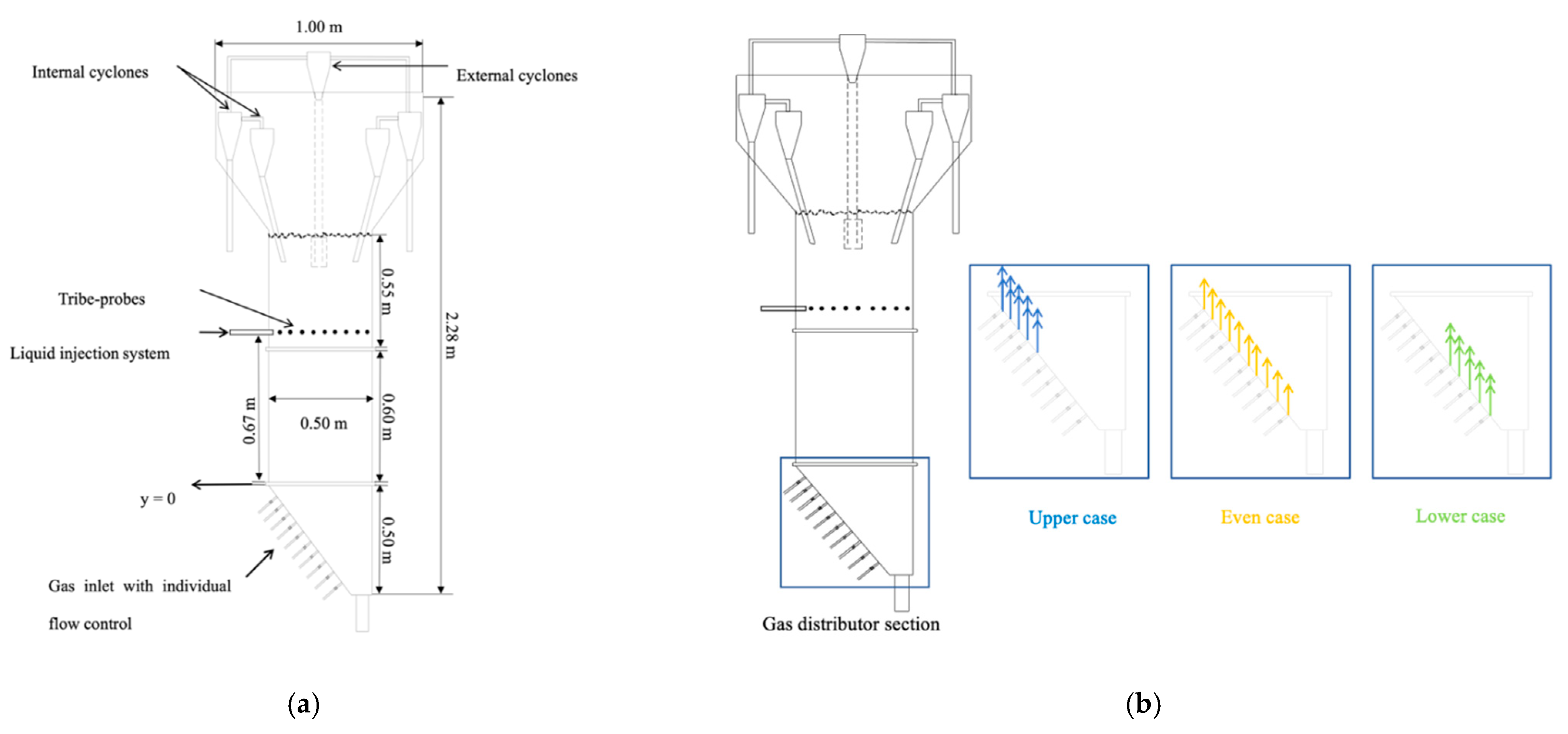
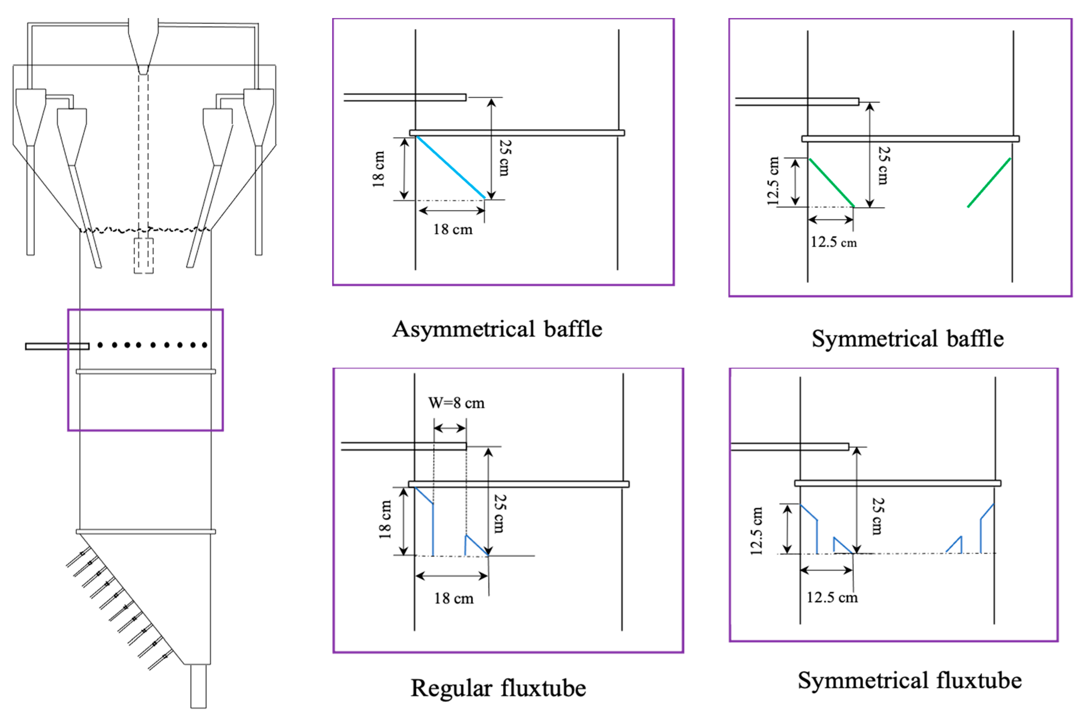
2. Configuration of the Fluidized Bed

The numerical simulations of a lab-scale bubbling fluidized bed reactor with a rectangular cross-section were carried out and the experimental data from Li et al. [15] were used to validate the numerical model.
The experimental setup is shown in Figure 1a, and consisted of a fluidized bed section and an expansion section. The bed thickness was 0.1 m in both sections. The total height of the unit was 2.28 m, and the unit width expanded from 0.5 m in the lower bed section to 1.0 m in the expansion section. Initially, the bed was filled with about 100 kg of silica sand with a Sauter-mean diameter of 190 μm. Air at ambient conditions with relative humidity below 12% was used as the fluidizing agent. The gas distributor consisted of two rows of 10 tuyeres, for a total of 20 tuyeres, distributed on an angled slope, as shown in Figure 1b. Each tuyere was supplied by a dedicated sonic orifice to maintain the required gas mass flow rate, which, in this study, was the same for each active tuyere. The minimum fluidization velocity was 0.033 m/s [15]. Three different inlet gas distribution cases were considered in the experiment as shown in Figure 1b. The base case is the even distributor in which the ten active gas tuyeres are evenly distributed. The second gas distribution case is the upper distributor with ten active tuyeres near the left-hand side of the column, and the third gas distribution is the lower distributor with ten active tuyeres near the right-hand side of the column. The gas bubble distribution was characterized from the lateral profile of the local gas bubble flux, i.e., the local volumetric flow of bubble gas per unit of column cross-sectional area.
Fluxtubes, which Wyatt et al. [30] patented, are used on industrial ring baffles to help reduce fouling of the stripping section of the Fluid Cokers by slowing down the downward motion of wet oil–coke agglomerates more effectively than baffles without fluxtubes. Different types of baffles were used in the bed, as shown in Figure 2 and Figure 3. The lower tip of each baffle was always at the height of 0.92 m from the bottom of the bed. The asymmetrical baffle was an open-ended right triangle shape baffle with an internal angle of 45°, which spanned the entire depth of the bed, from wall to wall. The dimensions of the asymmetrical baffle were 0.18 m × 0.18 m × 0.10 m on the left-hand side. The symmetrical baffles were at the same height on both sides of the bed with a relatively smaller size, which was 0.125 m × 0.125 m × 0.10 m. The baffle with fluxtube normally has a vertical tube inside it to provide the flow passage for the descending solids [30]. The dimensions of the symmetrical baffle with and without fluxtube are shown in Figure 2. Different fluxtube lengths and different fluxtube diameters, as shown in Figure 3, were also studied numerically in this paper.

3. Numerical Simulations

3.1. Computational Domain

All the simulations were carried out in a two-dimensional domain of the lab-scale fluidized bed reactor. Rather than using a uniform flat inlet boundary condition, which was implemented widely in other fluidized bed simulations, a specific gas inlet geometry was used based on the nozzle opening used in the experiments. In the experimental column, two rows of 10 tuyeres were used to supply gas over the whole column depth. For the purpose of this 2D simulation, a single row of the gas inlet was used to represent each couple of side-by-side tuyeres in the third direction. In the even case, all ten inlets were open to inject gas. For the upper case, only five inlets near the left-hand side of the fluidized bed reactor were open. In the lower case, five inlets near the right-hand side were open. To obtain the same inlet superficial velocity, the gas flow rate through each inlet in the lower and upper cases was double of the gas flowrate through each inlet in the even case, i.e., the total flow rates for all three cases were the same.

3.2. Governing Equations and Numerical Methods

The Euler–Euler approach was applied to simulate the flow in a gas–solid fluidized bed. Since the gas and solid phases could be present at the same time in the same computational volume, the volume fraction for each phase [47] was introduced in the governing equations. The governing equations for the two phases are summarized in Table 1. Other constitutive equations for the two-phase flows based on the kinetic theory of granular flow are listed in Table 2. The drag model takes into consideration the interactions between the gas and solid phases during the fluidization process. The momentum exchange coefficient between the phases, Kgs, was determined based on the Syamlal and O’Brien drag model [48]. The equations for the drag coefficient are shown in Table 3. The Syamlal and O’Brien drag model is based on the single-particle terminal velocity and adjusted based on the fluid properties and the expected minimum fluidization velocity.

3.3. Boundary Conditions

In each single inlet, the uniform gas velocity inlet condition was used. The inlet gas velocity was specified based on the superficial gas velocity used in the experiment. The atmosphere pressure was selected at the outlet boundary condition for the reactor. The no-slip boundary condition was used for the gas phase and the Johnson and Jackson [49] slip boundary condition was used for the solid phase.
The specularity coefficient φ is an empirical parameter that represents the particle–wall collision. The value of the specularity coefficient depends on the wall roughness. φ = 0 means a perfect specular collision, and φ = 1 means perfectly diffusion collision. Moreover, the value of 0.0001 is chosen based on an earlier study [50]. The details of the boundary conditions for the gas and solid phases are listed in Table 4.

4. Results and Discussion

The simulations were carried out using the unsteady solver. All results presented are the time-averaged results after the simulations reached a steady state.

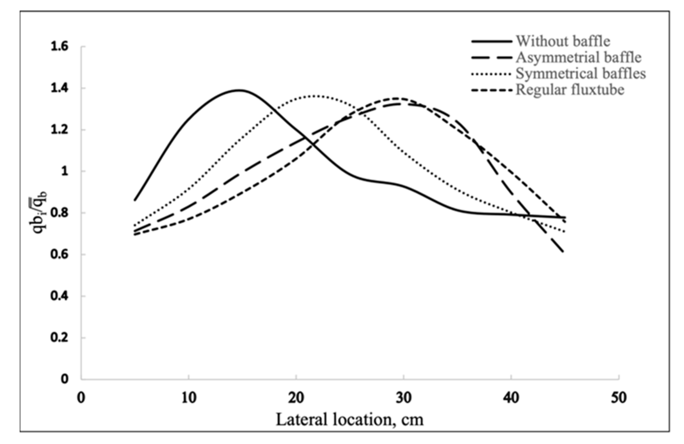
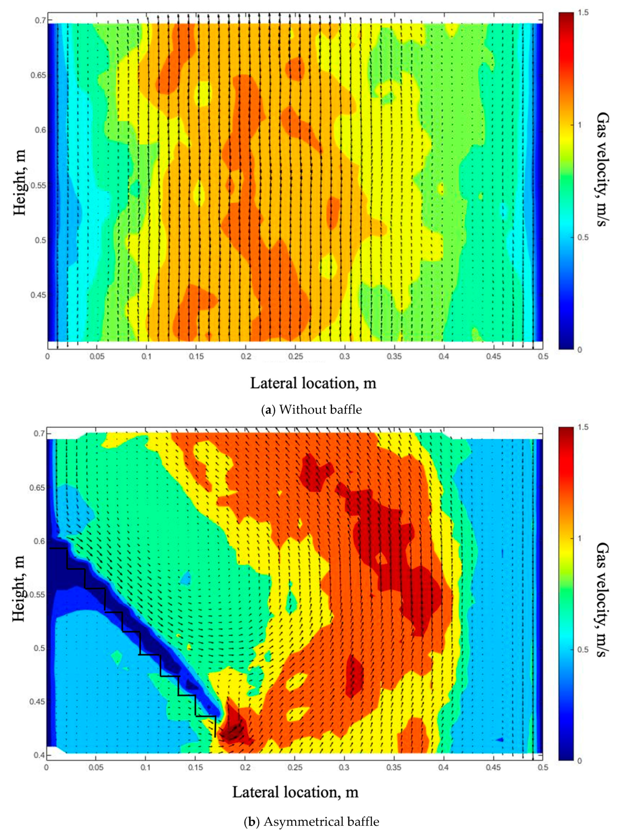
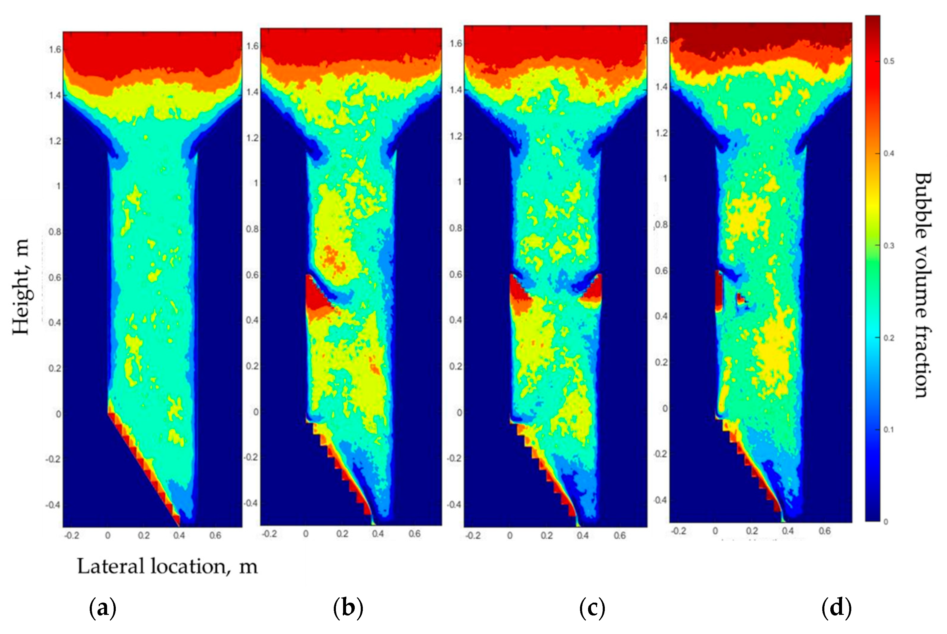
4.1. Effect of Baffles on the Gas Bubble Distribution

This section presents the results of the effect of baffles and fluxtubes on hydrodynamics in the bubble bed. Figure 4 shows the comparison of the lateral profiles of the gas bubble flux at the injection level for the cases with and without baffles and fluxtube. The use of the symmetrical baffle changes the asymmetrical bubble distribution in the case without a baffle to a profile that is nearly perfectly symmetrical. The bubble flow peak is moved from the left-hand side to the right-hand side when the asymmetrical baffle with and without the fluxtube is used compared to the case without a baffle. Figure 5 shows the bubble volume fraction in the baffle zone (0.40 m < y < 0.70 m) with and without baffle and regular fluxtube under an inlet superficial gas velocity of 0.4 m/s, which is near the transition from the bubbling to turbulent fluidization regimes. A “gas pocket” with a high gas concentration appears beneath all baffle types. Simultaneously, a denser, lower voidage region appears on the top of the baffle. The gas pocket under the baffle and the denser region on top of the baffle are greatly reduced when using the fluxtube, as shown in Figure 5d.
Figure 6 shows the contour of the gas velocity magnitude with the vector direction indicated by arrows. Without a baffle, it can be seen from Figure 6a that the bed can be separated into two zones: in the central core region, the gas moves quickly upward, and in the annulus region near the wall, the gas moves slowly upward or downward. However, with baffles, clear gas internal recirculation can be seen above both the asymmetrical baffle with and without the fluxtube and the symmetrical baffle, as shown in Figure 6b–d. It is also noticed that the gas internal recirculation patterns above the two symmetrical baffles are not symmetrical, because the gas flow from the sloped distributor is not symmetrical. The velocity contour for the case using the asymmetrical baffle with the fluxtube (Figure 6d) shows that the time-averaged velocity in the region outside of the recirculation zone is upward, indicating that gas bubbles mostly go up through the tube.
Figure 7 shows the contours of the gas bubble distribution in the fluidized bed with and without baffles. It shows that all the baffles tested, with or without the fluxtube, can affect the gas bubble flow in the entire bed. The use of the baffles results in an increase in the volume fraction of gas bubbles both below and above the baffles compared with the case without baffles.
The symmetrical baffle works better than other baffles on concentrating gas bubbles into the center part and the asymmetrical baffle with or without fluxtube works better on moving the bubble flow peak. By applying the asymmetrical baffle with fluxtube into the fluidized bed, it greatly improves the uneven distribution condition caused by baffle in the baffle zone.

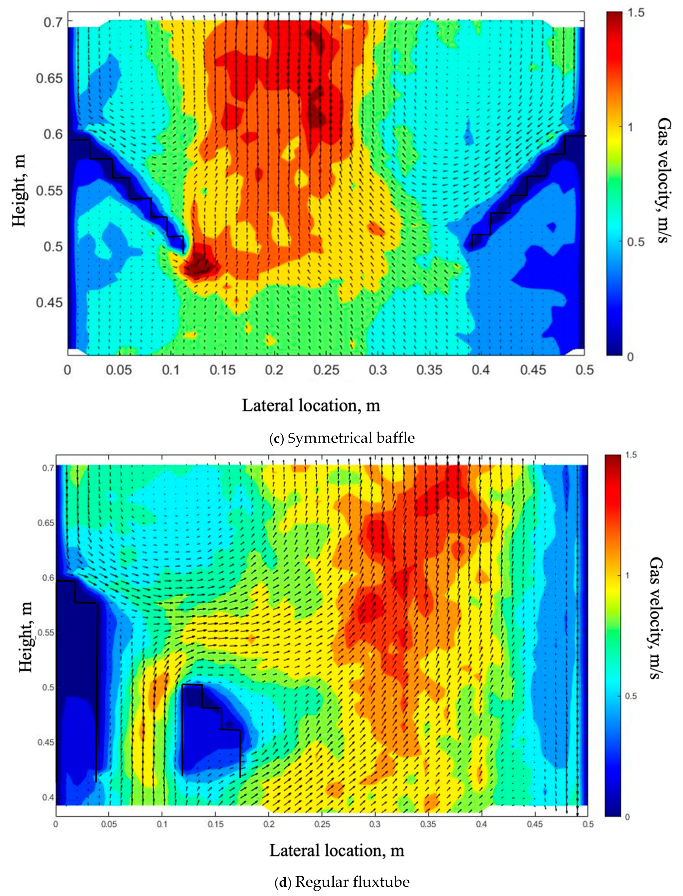
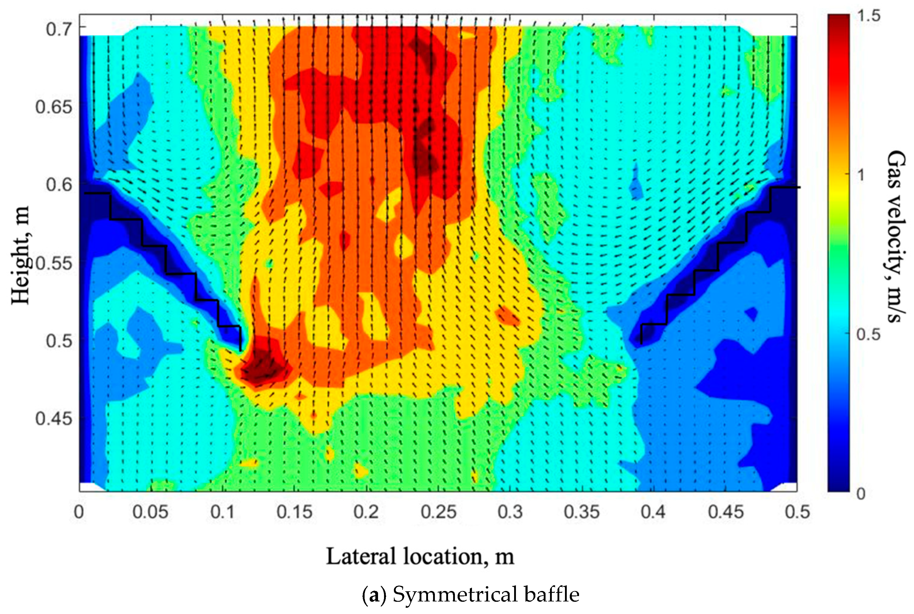
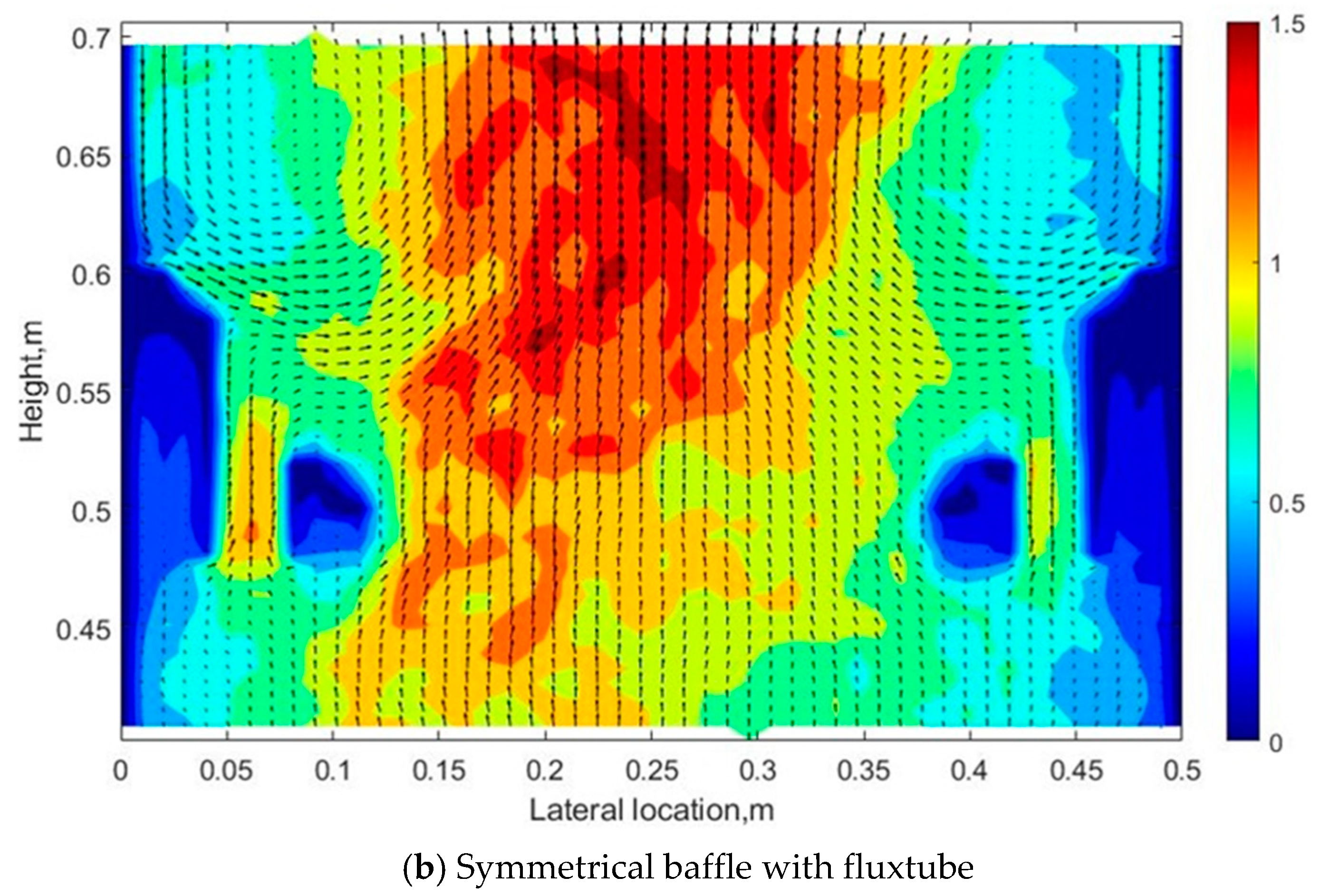
4.2. Effect of the Symmetrical Baffle

The effects of the symmetrical baffle with and without fluxtubes on the bubble distribution are compared in this section. Figure 8 shows the comparison of the lateral profiles of the gas bubble flux at the injection level for the cases with symmetrical baffles and fluxtube, which shows a similar bubble distribution profile as the baffle with and without fluxtube on the injection level. Figure 9 shows that with the symmetrical baffle, the use of the fluxtube reduces the sizes of both the “gas pocket” below the baffle and of the dense region above the baffle compared with the case without the fluxtube. According to Figure 9, the gas pocket under the baffle, with and without the fluxtube, is larger on the left-hand side than on the right-hand side, which is likely caused by the sloped gas inlet distributor that results in more gas bubbles on the left-hand side.
Figure 10 indicates that the presence of the fluxtube can also increases the bubble volume fraction throughout the bed. The gas bubbles flow towards the central region and their rise velocity increases in the central region due to the symmetrical baffle with and without the fluxtube, as shown in Figure 11. The relatively high gas velocity in the central region is due to the smaller opening area between the baffle tips and large recirculation of the gas above the baffle.
As for the gas bubble distribution on the injection level, the baffle with fluxtube does not improve the performance of the baffle. For the baffle zone, the baffle with fluxtube obviously decreases the “gas pocket” below the baffle and of the dense region above it, which is the same as for the asymmetrical baffle with fluxtube.

4.3. Effect of the Fluxtube Length

This section and the next one will explore the effect of the fluxtube configuration parameters on the bubble distributions in the bed and the even case is used for comparisons between different fluxtube parameters. This section focuses on the impact of the fluxtube length.
Three different fluxtube lengths—inside lengths of 18 cm (long), 16 cm (regular), and 12 cm (short)—with the same fluxtube diameter (8 cm) were considered in this study. Figure 12 shows that the regular fluxtube does not greatly change the impact of the baffle on the gas bubble flux on the injection level. On the other hand, both the long and short flux tubes enhance the shifting of the bubble gas flux towards the wall opposite of the baffle. However, the short fluxtube results in a more evenly distributed gas flow when compared to others, which seems consistent with the contours of the baffle zone (Figure 13). It seems that by interrupting the baffle and providing a channel for the motion of gas and solids, the fluxtube reduces the impact of the baffle. Additionally, the length of the fluxtube affects the function of the fluxtube as a channel.
It can be seen from Figure 13 that the “gas pocket” under the baffle with different fluxtube lengths is always much smaller than that without a fluxtube. The shortest fluxtube works best on reducing the size of the high solid holdup region on the top of the baffle. This is likely due to the agitation provided by the bubbles rising through the fluxtube, and it is easier for the gas bubbles to flow up thorough a shorter fluxtube. Figure 13 also shows that more gas bubbles are going through the short fluxtube than through the other two fluxtubes, since the gas holdup in the short fluxtube is higher than the other two fluxtubes. Figure 14 shows that the gas is more evenly distributed through the whole bed using the short fluxtube.

4.4. Effect of the Fluxtube Diameter

Different fluxtube diameters, with an inside width of 2 cm, 6 cm, and 8 cm, were considered. Figure 15 shows that the different diameters of fluxtube do not influence the gas bubble distribution on the injection level. Figure 16 shows that both the “gas pocket” below the baffle and the dense region above the baffle appear in all fluxtube diameters. Figure 16 and Figure 17 show that the gas holdup within the tube is larger for the smaller tube diameter. Accordingly, the change in the diameter of fluxtube does not affect the gas bubble profile at the injection level.

4.5. Combined Baffle and Gas Inlet Configuration

When there is no baffle, the effect of the inlet gas distributor configuration on the gas holdup in the baffle zone, where the baffle would otherwise be located, is not very significant, as shown in Figure 18a–c, although a gradual decrease in gas holdup from the left-hand side to the right-hand side appears for the lower distributor. On the other hand, when a baffle is present, one can see the gas distributions using a baffle with the three different gas distributors, as Figure 18d–f shows. It can be seen that the gas bubbles are concentrated in the central region due to the use of a baffle, and in all cases, there is a “gas pocket” below the baffle and a dense region above the baffle.
For all gas distributors, the fluxtube reduces the size of the “gas pocket” below the baffle and the dense region above the baffle, as shown in Figure 18g–i. The fluxtube also reduces the gas holdup in the baffle zone when compared to the baffle without a fluxtube for all three inlet gas distributors (Figure 18). Figure 19a–c shows the effect of different inlet gas distributor configurations on the gas holdup distribution throughout the fluidized bed. With the upper inlet gas distributor configuration, a region with a low gas holdup is found near the bottom of the bed as shown in Figure 19a, and Figure 19d,g shows that this region is reduced by the gas recirculation induced due to the baffle and is reduced significantly by the baffle with a fluxtube. Figure 19 confirms that the gas hold up is greatly increased by the baffle for all gas distributors, with a smaller increase in the bubble volume fraction using the fluxtube.

5. Conclusions

In this paper, a multi-phase Eulerian–Eulerian two-fluid method (TFM) coupled with the kinetic theory of granular flow (KTGF) was used to study the impact of baffles and fluxtube on the hydrodynamic of the gas–solid fluidized bed.
  • Adding a baffle can change the gas bubble radial distribution. A symmetrical baffle works better on concentrating bubbles to the center and an asymmetrical baffle works better on moving the gas bubble peak location.
  • An asymmetrical baffle with a fluxtube works better on evening the gas bubble distribution.
  • There is a “gas pocket” that appeared under the baffle, and a denser region appeared above the baffle under all gas inlet configurations.
  • A baffle can also increase the gas holdup throughout the bed, and this increase can be moderated by adding a fluxtube to the baffle.
  • The length of the fluxtube has a stronger impact on the column hydrodynamics than its diameter. The gas bubble distribution above the baffle can be changed by modifying the length of the fluxtube.

Author Contributions

Writing—original draft preparation, X.X.; writing—review and editing, C.B., L.Z. and C.Z.; supervision, C.B., C.Z., Y.S. and B.J. All authors have read and agreed to the published version of the manuscript.

Funding

This research was funded by China Scholarship Council (CSC).

Data Availability Statement

Not applicable.

Acknowledgments

The authors would like to acknowledge the NSERC-Syncrude Industrial Research Chair in Fluid Coking Technologies.

Conflicts of Interest

The authors declare no conflict of interest.

Nomenclature

α g volume fraction of gas phase
α s volume fraction of solid phase
ρ g gas density, kg m−3
ρ s solid density, kg m−3
ϑ g gas velocity, m s−1
ϑ s Solid velocity, m s−1
ε s gas volume fraction
ε g gas volume fraction
K g s Gas-solid momentum exchange coefficient
PPressure, Pa
p s particulate phase pressure, Pa
tflow time, s
U m f minimum fluidization velocity
U t particle terminal velocity
μshear viscosity
Θ s granular temperature, m2 s−2

References

  1. Yang, W. Handbook of Fluidization and Fluid-Particle Systems; Marcel Dekker: New York, NY, USA, 2003. [Google Scholar]
  2. Geldart, D. Fluidization Engineering, 2nd ed.; Butterworth-Heinemann: Oxford, UK, 1969. [Google Scholar]
  3. Yates, J.G.; Lettieri, P. Fluidized-Bed Reactors: Processes and Operating Conditions; Springer: New York, NY, USA, 2016. [Google Scholar]
  4. Grace, J.R.; Bi, X.; Ellis, N. Essentials of Fluidization Technology; Wiley: Hoboken, NJ, USA, 2020. [Google Scholar]
  5. Smith, P.G. Applications of Fluidization to Food Processing; John Wiley & Sons: Hoboken, NJ, USA, 2008. [Google Scholar]
  6. Wyatt, J.T.; Jones, E.N.; Chen, A.U.; Sutton, R.; Healy, T.M.; Suryo, R.; Lampert, L.; Miller, J. Circulating Fluidized Bed Reactor With Improved Circulation. U.S. Patent 8,435,452 B2, 14 June 2016. [Google Scholar]
  7. Cochet, Y.; Briens, C.; Berruti, F.; McMillan, J.; Careaga, F.S. Impact of column geometry and internals on gas and particle flows in a fluidized bed with downward solids circulation: Effect of lateral injection profile and baffles. Powder Technol. 2020. [Google Scholar] [CrossRef]
  8. Zhang, Y.; Lu, C.; Grace, J.R.; Bi, X.; Shi, M. Gas back-mixing in a two-dimensional baffled turbulent fluidized bed. Ind. Eng. Chem. Res. 2008, 47, 8484–8491. [Google Scholar] [CrossRef]
  9. Zhang, Y.; Grace, J.R.; Bi, X.; Lu, C.; Shi, M. Effect of louver baffles on hydrodynamics and gas mixing in a fluidized bed of FCC particles. Chem. Eng. Sci. 2009, 64, 3270–3281. [Google Scholar] [CrossRef]
  10. Wang, S.; Luo, K.; Hu, C.; Fan, J. CFD-DEM study of the effect of ring baffles on system performance of a full-loop circulating fluidized bed. Chem. Eng. Sci. 2019, 196, 130–144. [Google Scholar] [CrossRef]
  11. Rossbach, V.; Utzig, J.; Decker, R.K.; Noriler, D.; Soares, C.; Martignoni, W.P.; Meier, H.F. Gas-solid flow in a ring-baffled CFB riser: Numerical and experimental analysis. Powder Technol. 2019, 345, 521–531. [Google Scholar] [CrossRef]
  12. Shah, M.T.; Pareek, V.K.; Evans, G.M.; Utikar, R.P. Effect of baffles on performance of fluid catalytic cracking riser. Particuology 2018, 38, 18–30. [Google Scholar] [CrossRef]
  13. Chalermsinsuwan, B.; Samruamphianskun, T.; Piumsomboon, P. Effect of operating parameters inside circulating fluidized bed reactor riser with ring baffles using CFD simulation and experimental design analysis. Chem. Eng. Res. Des. 2014, 92, 2479–2492. [Google Scholar] [CrossRef]
  14. Chen, Y.-M. Recent advances in FCC technology. Powder Technol. 2006, 163, 2–8. [Google Scholar] [CrossRef]
  15. Li, Y.; Careaga, F.S.; Briens, C.; Berruti, F.; McMillan, J. Impact of local fluidized bed hydrodynamics on the distribution of liquid sprayed into the bed. Powder Technol. 2020, 367, 326–335. [Google Scholar] [CrossRef]
  16. Veluswamy, G.K.; Upadhyay, R.K.; Utikar, R.P.; Tade, M.; Evans, G.; Glenny, M.E.; Roy, S.; Pareek, V.K. Hydrodynamic study of fluid catalytic cracker unit stripper. Ind. Eng. Chem. Res. 2013, 52, 4660–4671. [Google Scholar] [CrossRef]
  17. Careaga, F.S.; Briens, C.; Berruti, F.; McMillan, J.; Gray, M. Agglomerate behavior in a recirculating fluidized bed with sheds: Effect of sheds. Adv. Powder Technol. 2018, 29, 1758–1770. [Google Scholar] [CrossRef]
  18. Sadeghbeigi, R. Fluid Catalytic Cracking Handbook, 3rd ed.; Butterworth-Heinemann: Oxford, UK, 2020. [Google Scholar]
  19. Fan, Y.; Chenglin, E.; Shi, M.; Xu, C.; Gao, J.; Lu, C. Diffusion of feed spray in fluid catalytic cracker riser. AIChE J. 2009. [Google Scholar] [CrossRef]
  20. Issangya, A.S.; Reddy Karri, S.B.; Knowlton, T.M. Effect of Baffles on Jet Streaming in Deep Fluidized Beds of Group a Particles; Particulate Solid Research, Inc.: Chicago, IL, USA, 2008. [Google Scholar]
  21. Zhang, Y.; Wang, H.; Chen, L.; Yang, Y.; Lu, C. Effect of Baffle Type on Particle Segregation in a Binary Gas-Solids Fluidized Bed; Chemical Industry Press: Beijing, China, 2014; pp. 91–97. [Google Scholar]
  22. Zhang, Y.; Wang, H.; Chen, L.; Lu, C. Systematic investigation of particle segregation in binary fluidized beds with and without multilayer horizontal baffles. Ind. Eng. Chem. Res. 2012, 51, 5022–5036. [Google Scholar] [CrossRef]
  23. Yang, S.; Li, H.; Zhu, Q. Experimental study and numerical simulation of baffled bubbling fluidized beds with Geldart A particles in three dimensions. Chem. Eng. J. 2015, 259, 338–347. [Google Scholar] [CrossRef]
  24. Pardo Reyes, L.A.; Reyes, L.A.P. Effect of Temperature and Successive Sprays on Liquid Distribution in Fluidized Beds. Master’s Thesis, Western University, London, ON, Canada, 28 July 2015. [Google Scholar]
  25. Yang, N.; Zhou, Y.L.; Qi, T.Y.; Lu, Z.Y. Bitumen cracking using liquid injection. Pet. Sci. Technol. 2016, 34, 1164–1171. [Google Scholar] [CrossRef]
  26. Canada’s Oil & Natural Gas Producers (CAPP). Oil Sands Oil Sands; Canada’s Oil & Natural Gas Producers (CAPP): Celgary, AB, Canada, 2018. [Google Scholar]
  27. House, P.K.; Saberian, M.; Briens, C.L.; Berruti, F.; Chan, E. Injection of a liquid spray into a fluidized bed: Particle-liquid mixing and impact on fluid coker yields. Ind. Eng. Chem. Res. 2004, 43, 5663–5669. [Google Scholar] [CrossRef]
  28. Montes, A. Factors Affecting Bed Agglomeration in Bubbling Fluidized Bed Biomass Boilers. Master’s Thesis, Western University, London, ON, Canada, 20 August 2014. [Google Scholar]
  29. Morales, C.B. Development and Application of an Experimental Model for the Fluid Coking Process. Master’s Thesis, Western University, London, ON, Canada, 16 August 2013. [Google Scholar]
  30. Wyatt, J.T.; Jones, E.N.; Chen, A.U.; Sutton, C.R.; Healy, T.M.; Suryo, R.; Lampert, L.; Miller, J. Circulating Fluid Bed Reactor with Improved Circulation. U.S. Patent 843,545,2B2, 7 May 2007. [Google Scholar]
  31. Javier Sanchez, F.C. Hydrodynamics in Recirculating Fluidized Bed Mimicking the Stripper Section of the Fluid Coker. Ph.D. Thesis, Western University, London, ON, Canada, 10 December 2013. [Google Scholar]
  32. Jahanmiri, M. Use of a Baffle to Enhance the Distribution of a Liquid Sprayed into a Gas-Solid Fluidized Bed. Master’s Thesis, Western University, London, ON, Canada, 24 April 2017. [Google Scholar]
  33. Yang, Z.; Zhang, Y.; Zhang, H. CPFD simulation on effects of louver baffles in a two-dimensional fluidized bed of Geldart A particles. Adv. Powder Technol. 2019. [Google Scholar] [CrossRef]
  34. Samruamphianskun, T.; Piumsomboon, P.; Chalermsinsuwan, B. Effect of ring baffle configurations in a circulating fluidized bed riser using CFD simulation and experimental design analysis. Chem. Eng. J. 2012, 210, 237–251. [Google Scholar] [CrossRef]
  35. Nagata, K.; Tadama, T.; Murase, K.; Bando, Y.; Nakamura, M.; Toyama, S. Simulation of gas and particle behaviors in moving-fluidized bed with inclined baffle plates by two-fluid model. J. Chem. Eng. Jpn. 1999, 32, 816–820. [Google Scholar] [CrossRef]
  36. Yang, S.; Peng, L.; Liu, W.; Zhao, H.; Lv, X.; Li, H.; Zhu, Q. Simulation of hydrodynamics in gas-solid bubbling fluidized bed with louver baffles in three dimensions. Powder Technol. 2016, 296, 37–44. [Google Scholar] [CrossRef]
  37. Cloete, S.; Zaabout, A.; Johansen, S.T.; Annaland, M.V.S.; Gallucci, F.; Amini, S. The generality of the standard 2D TFM approach in predicting bubbling fluidized bed hydrodynamics. Powder Technol. 2013, 235, 735–746. [Google Scholar] [CrossRef] [Green Version]
  38. Wang, Y.; Zou, Z.; Li, H.; Zhu, Q. A new drag model for TFM simulation of gas–solid bubbling fluidized beds with Geldart-B particles. Particuology 2014, 15, 151–159. [Google Scholar] [CrossRef]
  39. Huilin, L.; Wentie, L.; Feng, L.; Guangbo, Z.; Yurong, H. Yurong, Eulerian simulations of bubble behaviour in a two-dimensional gas-solid bubbling fluidized bed. Int. J. Energy Res. 2002, 26, 1285–1293. [Google Scholar] [CrossRef]
  40. Askaripour, H.; Dehkordi, A.M. Simulation of 3D freely bubbling gas–solid fluidized beds using various drag models: TFM approach. Chem. Eng. Res. Des. 2015, 100, 377–390. [Google Scholar] [CrossRef]
  41. Ullah, A.; Hong, K.; Gao, Y.; Gungor, A.; Zaman, M. An overview of Eulerian CFD modeling and simulation of non-spherical biomass particles. Renew. Energy 2019, 141, 1054–1066. [Google Scholar] [CrossRef]
  42. Li, T.; Grace, J.; Bi, X.; Reid, K.; Wormsbecker, M. Numerical investigation of FLUID COKINGTM units, Part I: Hydrodynamics of a scaled cold flow model. Can. J. Chem. Eng. 2012, 90, 442–456. [Google Scholar] [CrossRef]
  43. Li, T.; Pougatch, K.; Salcudean, M.; Grecov, D. Numerical simulation of single and multiple gas jets in bubbling fluidized beds. Chem. Eng. Sci. 2009, 64, 4884–4898. [Google Scholar] [CrossRef]
  44. Li, T.; Pougatch, K.; Salcudean, M.; Grecov, D. Mixing of secondary gas injection in a bubbling fluidized bed. Chem. Eng. Res. Des. 2009, 87, 1451–1465. [Google Scholar] [CrossRef]
  45. Liu, Y.; Yang, J.; Lan, X.; Gao, J. Numerical simulation of chemical stripping process in resid fluid catalytic cracking stripper. Int. J. Chem. React. Eng. 2014, 12, 525–537. [Google Scholar] [CrossRef]
  46. Benzarti, S.; Mhiri, H.; Bournot, P. Numerical simulation of baffled circulating fluidized bed with Geldart B particles. Powder Technol. 2021, 380, 629–637. [Google Scholar] [CrossRef]
  47. ANSYS Inc. ANSYS Fluent Theory Guide; ANSYS Inc.: Canonsburg, PA, USA, 2016; pp. 1–812. [Google Scholar]
  48. Syamlal, M.; Rogers, W.; O’Brien, T.J. MFIX Documentation Theory Guide; Technical Note; USDOE Morgantown Energy Technology Center: Morgantown, WV, USA, 1993. [Google Scholar]
  49. Johnson, P.C.; Jackson, R. Frictional–collisional constitutive relations for granular materials, with application to plane shearing. J. Fluid Mech. 1987, 176, 67–93. [Google Scholar] [CrossRef]
  50. Hong, K.; Wang, W.; Zhou, Q.; Wang, J.; Li, J. An EMMS-based multi-fluid model (EFM) for heterogeneous gas-solid riser flows: Part, I. Formulation of structure-dependent conservation equations. Chem. Eng. Sci. 2012, 75, 376–389. [Google Scholar] [CrossRef]
Figure 1. (a) Lab-scale bubbling fluidized bed; (b) Different gas inlet distributor configurations.
Processes 09 01150 g001
Figure 2. Location and dimensions of different baffles.
Processes 09 01150 g002
Figure 3. Baffle with fluxtubes of different sizes.
Processes 09 01150 g003
Figure 4. Lateral gas bubble distributions at the injection level with and without baffle and regular fluxtube under the superficial gas velocity of 0.4 m/s using the even inlet configuration.
Processes 09 01150 g004
Figure 5. Bubble contours in the baffle zone (0.40 m < y < 0.70 m) with and without baffle and regular fluxtube under the superficial gas velocity of 0.4 m/s using the even gas inlet distributor configuration.
Processes 09 01150 g005
Figure 6. Gas velocity magnitude contours with velocity vectors at the baffle zone (0.40 m < y < 0.70 m) with and without baffle and regular fluxtube under the superficial gas velocity of 0.4 m/s using the even inlet gas distributor.
Processes 09 01150 g006aProcesses 09 01150 g006b
Figure 7. Gas holdup contours in the entire fluidized bed reactor with and without baffle and regular fluxtube under the superficial gas velocity of 0.4 m/s using the even case inlet configuration. (a) Without baffle; (b) Asymmetrical baffle; (c) Symmetrical baffle; (d) Asymmetrical baffle with the regular fluxtube.
Processes 09 01150 g007
Figure 8. Radial gas bubble distribution profiles at injection level using the symmetrical baffle with and without the fluxtube under the superficial gas velocity of 0.4 m/s for the even gas inlet configuration.
Processes 09 01150 g008
Figure 9. Gas holdup contours at the baffle zone (0.40 m < y < 0.70 m) using the symmetrical baffles with and without the regular fluxtube under the superficial gas velocity of 0.4 m/s for the even gas inlet configuration.
Processes 09 01150 g009
Figure 10. Gas holdup contours in the entire fluidized bed reactor using the symmetrical baffle with and without and the regular fluxtube under the superficial gas velocity of 0.4 m/s for even gas inlet configuration.
Processes 09 01150 g010
Figure 11. Gas velocity magnitude contours with velocity directions at the baffle zone (0.40 m < y < 0.70 m) using the symmetrical baffle with and without the regular fluxtube under the superficial gas velocity of 0.4 m/s for the even gas inlet configuration.
Processes 09 01150 g011aProcesses 09 01150 g011b
Figure 12. Radial gas bubble distributions at injection level using the asymmetrical baffle without a fluxtube and with fluxtube baffles of different lengths under the superficial gas velocity of 0.4 m/s for the even gas inlet configuration.
Processes 09 01150 g012
Figure 13. Bubble volume fraction contours at the baffle zone (0.40 m < y < 0.70 m) using the asymmetrical baffle without a fluxtube and with fluxtubes of different lengths under the superficial gas velocity of 0.4 m/s for the even gas inlet configuration.
Processes 09 01150 g013
Figure 14. Bubble volume fraction contours in the entire fluidized bed reactor using the asymmetrical baffle without a fluxtube and with fluxtubes baffle of different lengths under the superficial gas velocity of 0.4 m/s for the even gas inlet configuration.
Processes 09 01150 g014
Figure 15. Radial gas bubble distribution profile at injection level using the asymmetrical baffle without a fluxtube and with fluxtubes of different widths under the superficial gas 0.4 m/s with even gas inlet configuration.
Processes 09 01150 g015
Figure 16. Bubble volume fraction contours at the baffle zone (0.40 m < y < 0.70 m) using the asymmetrical baffle without a fluxtube and with fluxtubes of different widths under the superficial gas velocity of 0.4 m/s for the even gas inlet configuration.
Processes 09 01150 g016
Figure 17. Bubble volume fraction contours in the entire fluidized bed reactor using the asymmetrical baffle without a fluxtube and with fluxtubes of different widths under the superficial gas velocity of 0.4 m/s for the even gas inlet configuration.
Processes 09 01150 g017
Figure 18. Bubble volume fraction contours at the baffle zone (0.40 m < y < 0.70 m) using the asymmetrical baffle without a fluxtube and with the regular fluxtube for different gas inlet configurations under the superficial gas velocity of 0.4 m/s.
Processes 09 01150 g018
Figure 19. Bubble volume fraction contours in the entire fluidized bed reactor without and with baffle and fluxtube for different gas inlet configurations under the superficial gas velocity of 0.4 m/s, a. Upper, b. Even, c. Lower, d. Upper (Asymmetrical baffle), e. Even (Asymmetrical baffle), f. Lower (Asymmetrical baffle), g. Upper (Fluxtube), h. Even (Fluxtube), i. Lower (Fluxtube).
Processes 09 01150 g019aProcesses 09 01150 g019b
Table 1. Governing equations.
Gas Phase
Continuity t ( α g ρ g ) + ( α g ρ g ϑ g ) = 0 , (1)
Momentum t ( α g ρ g ϑ g ) + ( α g ρ g ϑ g ϑ g ) = α g p +   τ = g + α g   ρ g g + K g s ( ϑ s ϑ g ) , (2)
Volume fraction α s + α g = 1 ,
Solid Phase
Continuity t ( α s ρ s ) + ( α s ρ s ϑ s ) = 0 , (3)
Momentum t ( α s ρ s ϑ s ) + ( α s ρ s ϑ s ϑ s ) = α s p +   τ = s + α s   ρ s g + K g s ( ϑ g ϑ s ) , (4)
Table 2. Constitutive equations.
The granular temperature transport equation:
3 2 [ t ( ρ s α s Θ s ) + · ( ρ s α s ϑ s Θ s ) ] = ( p s I = + τ = s ) : ϑ s + · ( k Θ s Θ s ) +   φ l s (5)
Where
( p s I = + τ = s ) : ϑ s is the generation of energy by the solid stress tensor;
k Θ s Θ s is the diffusion of energy;
γ Θ s is the collisional dissipation of energy;
φ l s is the energy exchange between the lth solid phase and the sth solid phase;
The stress tensors for gas and solid phase are:
τ = g = α g μ g ( ν g + ν g T ) 2 3 μ g · ν g I = ,(6)
τ = s = α s μ s ( ν s + ν s T ) + α s ( λ s 2 3 μ s ) · ν s I = ,(7)
Solid shear viscosity:
μ s = μ s , c o l + μ s , k i n + μ s , f r ,(8)
Collisional viscosity:
μ s , c o l = 4 5 α s ρ s d s g 0 , s s ( 1 + e s s ) ( Θ s π ) 1 / 2 α s ,(9)
Kinetic viscosity:
μ s , k i n = α s d s ρ s Θ s π 6 ( 3 e s s ) [ 1 + 2 5 ( 1 + e s s ) ( 3 e s s 1 ) α s g 0 , s s ] ,(10)
Frictional viscosity:
μ s , f r = P f r i c t i o n sin φ 2 I 2 D , (11)
Solid bulk viscosity:
λ s = 4 3 α s 2 ρ s d s g 0 , s s ( 1 + e s s ) ( Θ s π ) 1 2 , (12)
Solid pressure:
p s = α s ρ s Θ s + 2 ρ s ( 1 + e s s ) α s 2 g 0 , s s Θ s , (13)
Radial distribution function:
g 0 , s = [ 1 ( α s α s , m a x ) 1 3 ] 1 , (14)
Diffusion coefficient of granular temperature (Syamlal–O’Brien):
k Θ s = 15 d s ρ s α s Θ s π 4 ( 41 33 η ) [ 1 + 12 5 η 2 ( 4 η 3 ) α s g 0 , s s + 16 15 π ( 41 33 η ) η α s g 0 , s s ] ,(15)
η = 1 2 ( 1 + e s s ) , (16)
Table 3. Momentum exchange coefficient.
Syamlal–O’Brien Drag Function
K g s = 3 α s α g ρ g 4 ν r , s 2 d s C D ( R e s ν r , s ) | ν s ν g | , (17)
ν r , s = 0.5 ( A 0.06 R e s + ( 0.06 R e s ) 2 + 0.12 R e s ( 2 B A ) + A 2 ) , (18)
A = α g 4.14 ,
B = c 1 · α g 1.28 for α g 0.85 ,
B = α g d 1          for α g > 0.85 ,
Where d 1 = 1.28 + log 10 C 1 log 10 0.85
C D = ( 0.63 + 4.8 ( R e s ν r , s ) ) ,
R e s = ρ g d s | ν s ν g | μ g ,
Where CD is the drag coefficient and Res is the Reynolds number
Table 4. Boundary conditions.
Inlet of Gas Phase
Superficial gas velocity
Wall
Gas-phaseNo-slip velocity
Solid-phasePartial-slip
Specularity coefficient:0.0001
Particle-wall restitution coefficient: 0.9
Outlet
Gas-phasePressure-outlet
Solids phasePressure-outlet
Publisher’s Note: MDPI stays neutral with regard to jurisdictional claims in published maps and institutional affiliations.

