Article

Study on Hazardous Areas of Hydrogen Fluoride Diffusion Based on CFD Simulation

1
Department of Safety Science and Engineering, University of Science and Technology Beijing, Beijing 100083, China
2
North Industries Group Pinance Company LTD., Beijing 100032, China
*
Author to whom correspondence should be addressed.
Processes 2021, 9(9), 1545; https://doi.org/10.3390/pr9091545
Submission received: 24 July 2021 / Revised: 17 August 2021 / Accepted: 23 August 2021 / Published: 30 August 2021
(This article belongs to the Special Issue Recent Advances in Chemical Process Safety)

Abstract

:
Hydrogen fluoride (HF) is a typical dangerous gas in the fluorine chemical industry. Its leakage is one of the most common types of accidents in this industry, and it poses a serious threat to personnel safety and health, environmental sanitation, and social stability. In this paper, the process and consequences of an HF leakage accident in a fluorine chemical plant were simulated by using computational fluid dynamics (CFD) simulation software, and hazardous areas (lethal area, severe injury area, light injury area, and maximum allowable concentration area) of HF diffusion were determined according to the HF concentration corresponding to the degree of personal injury. Moreover, the effects of wind speed and height on hazardous areas were analyzed. The research results of this paper provide model support for similar enterprises to predict the consequences of harmful gas leakage accidents, and give suggestions on emergency evacuation and rescue work, which have practical application significance.

1. Introduction

Hazardous gas leakage and diffusion accidents have a wide range and can cause large losses [1,2,3,4]. Hydrogen fluoride (HF) is a typical dangerous gas in the fluorine chemical industry. There have been many HF leakage accidents. In 2009, in the United States, thousands of people were evacuated urgently because of a hydrofluoric acid leakage in a fluorine chemical plant. In 2012, a HF leakage accident occurred in Gumi, South Korea, which caused necrosis of vegetation within 1 km and toxic gas staying for more than ten days [5]. In 2018, three deaths in China occurred due to HF poisoning.
In the 1970s and 1980s, many scholars conducted field experiments on gas leakage and diffusion, such as Burro [6,7,8,9], Coyote [10,11], Thorney Island [12,13,14,15,16,17], Maplin Sands [18], and Goldfish [19]. The general law of gas diffusion was concluded through the analysis of gas phenomena. However, high experimental cost, complex influencing factors, and toxic properties of the gases set a limit for field experiments.
Considering the cost and uncontrollability of harmful gas leakage and diffusion experiments, the current main research method in this field is computational fluid dynamics (CFD) simulation [20,21,22,23]. In 2011, Tauseef et al. [24] used data from the 26th experiment of Thorney Island in the United States to study the accuracy of various CFD turbulence models. The research results showed that the gas diffusion calculated by the realizable k-ε model was the closest to the actual situation. The realizable k-ε model can not only capture the gravity drop related to the diffusion of heavy gases, but also clearly describe the gas movement in the presence of obstacles. In 2016, Fiates et al. [25] conducted a leakage and diffusion experiment of carbon dioxide. Then, they used CFD software to reproduce the experiment, and the simulation results were in good agreement with the experimental results. In 2017, Yang et al. [5] used CFD software to recover an HF leakage accident in South Korea in 2012 and studied the environmental impact of the accident. The above studies show that the CFD simulation method is reliable and can accurately describe the phenomenon of harmful gas diffusion in various scenarios. In order to analyze the serious consequences and influencing factors of harmful gas diffusion, in 2013, Wang et al. [26] explored the diffusion law of oil gas after leakage through experiments and simulations, and set the area where the oil gas concentration exceeded the minimum concentration of strong explosion as a hazardous area. The effect of the leakage flow rate on the hazardous area was also discussed in the research. In 2014, Dadashzadeh et al. [27] simulated the diffusion of carbon monoxide, nitrogen dioxide, and methane in a specific area and divided the risk area for a single person according to the highest concentration of different gases that do not cause harm to the human body. In 2019, Souza et al. [28] proposed a method for quickly estimating the extension volume of hazardous areas based on CFD software and studied the effects of transport properties, orifice size, gas molar mass, temperature, pressure, and lower explosion limit on the extension of hazardous areas. In 2020, Barros et al. [29] discussed the effects of wind direction and speed on the volume of gas clouds based on the results of CFD calculations, and predicted the hazard level of the area according to relevant international standards. Overall, the harmful gas diffusion phenomenon has been widely studied, but little attention has been paid to the specific harmful effects of the gases on the human body. Moreover, the changes in the gas hazardous area are affected by many factors. The distribution and changing laws of various hazardous areas at different heights are still unclear.
To improve understanding of how the harmful effects of HF on the human body are reflected in the hazardous area, in this paper, the method of dividing the hazardous area of the fluorine chemical plant according to the maximum allowable concentration in the HF occupational exposure scenarios and the concentrations that cause light, severe, and lethal human injuries is proposed. In addition, in order to explore the influencing factors more comprehensively, the changing law of various hazardous areas at different heights is investigated through CFD software calculation and visualization methods. The results can provide a technical basis for the research and judgment of the risk situation of harmful gases leakage accidents in fluorine chemical enterprises. Safety workers can refer to the prediction model to deploy emergency resources, implement emergency rescue measures, and plan escape routes and safe areas.

2. Methodology

2.1. Modeling and Verification

To verify the reliability of the CFD simulation method, Fluent was used in this study to restore the Goldfish HF leakage and diffusion experiment.

2.1.1. The CFD Model

Fluent is a solver based on the finite element volume method. The priority of this method is to solve the convection-diffusion equation in the form of the Navier–Stokes equation (momentum conservation equation) which is shown in Equation (1). The basis for judging the convergence of the solution result is that the fluid reaches the conservation of mass, momentum, and energy in each control unit (grid) in the computational domain. The mass and energy conservation equations are shown in Equations (2) and (3) [30],
t ρ u   +       ρ u u   = p +     τ =   +   ρ g
ρ t +     ρ u   = 0
ρ c v T t +     ρ u c p T   =     k T T
where ρ is the density, t is the time, u is the velocity, p is the pressure, τ is the shear stress, g is the gravity acceleration, c v and c p are the specific heats, T is the temperature, and k T is the thermal conductivity.
The gas diffusion process is complicated. A suitable turbulence model can more accurately calculate the actual situation. Fluent provides many turbulence models, such as the standard k-ε model [31], realizable k-ε model [32], and Reynolds stress model [33]. Some studies have shown that the standard k-ε model is more suitable for gas flow scenarios outside complex buildings [30,34]. Therefore, this paper chooses the standard k-ε model, which is shown in Equations (4) and (5) [35],
t ρ k   +   x j ρ k u ¯ j   =   x j μ + ρ C μ k 2 σ k ε k x j   +   ρ C μ k 2 ε u ¯ i x j + u ¯ j x i u ¯ i x j ρ ε
t ρ ε   +   x j ρ ε u ¯ j   =   x j μ + ρ C μ k 2 σ ε ε ε x j   +   C 1 ε ε k ρ C μ k 2 ε u ¯ i x j + u ¯ j x i u ¯ i x j     C 2 ε ρ ε 2 k
where k is the turbulent kinetic energy, ε is the rate of dissipation, C 1 ε , C 2 ε and C μ are constants, 1.44, 1.92, and 0.09, respectively, and σ k and σ ε are the turbulent Prandtl numbers for k and ε, 1.0 and 1.3, respectively.

2.1.2. Model Validation

Considering the size of the computational domain of the simulation in this study, the HF concentration data of the Goldfish 2, 3 experiments at 300 m from the leak source [5] were selected in this paper for reliability verification.
In the Goldfish 2 and 3 experiments, HF was stored in a tank in liquid form. The density of the fluid was 956.50 kg/m3, and the gauge pressure of the tank was 6.67 × 10⁵ Pa. The liquefied HF transformed into a gaseous state at the moment of leakage. The research by Yang et al. [5] showed that there was not much difference between the results of single-phase and two-phase simulations. Therefore, the single-phase simulation method was adopted in this paper. The leakage direction was consistent with the wind direction, the atmospheric stability grade was D, and the ground surface roughness was 0.003. Other relevant information and data are shown in Table 1 [19].
The final calculation domain had a length of 360 m, a width of 50 m, and a height of 30 m. The leaking storage tank was simplified as a cylinder with a diameter of 2 m and a height of 2 m. After the grids were divided in the ICEM software, the total number of grids obtained was 445,304. Fluent calculation results showed that the corresponding concentrations of GF2 and 3 were 2.3587 × 10⁻⁵ kg/m3 and 2.2021 × 10⁻⁵ kg/m3, respectively. The comparison with the actual experimental measurement values is shown in Table 2.
The relative error of the data is within the acceptable range. Therefore, the simulation method can be applied to divide and analyze the hazardous areas of a certain plant area after an HF leakage accident.

2.2. Simulation Application Background

In this study, a fluorine chemical plant in Quzhou City, Zhejiang Province is selected for numerical simulation of the HF leakage accident. According to the wind direction and wind speed data of Quzhou in 2019 and 2020 published by the China Meteorological Administration, the most common wind direction in this area was the northeast wind. In 2019, it accounted for 65.48% of the annual days, and in 2020, it accounted for 39.08% of the annual days. The most common wind speed was 1.6–5.4 m/s. In 2019, it accounted for 35.62% of the annual days, and in 2020, it accounted for 60% of the annual days. Therefore, the simulated wind direction in this study is the northeast wind, and the simulated wind speed is 0, 1, 2, 4, and 6 m/s, respectively. The storage conditions of HF are the same as the Goldfish 2, 3 experiments, and the simulation is still single-phase. According to the actual situation of the local environment, the model parameters are revised. This study establishes a HF leakage model with a length of 570 m, a width of 400 m, and a height of 100 m. The total number of grids is 823,302.
Based on the human injuries caused by HF [36,37], the diffusion area is divided into four categories: lethal area, severe injury area, light injury area, and maximum allowable concentration area (MAC area). The description of these areas is listed in Table 3.

3. Results and Discussion

3.1. Diffusion Law of HF under Different Wind Speeds

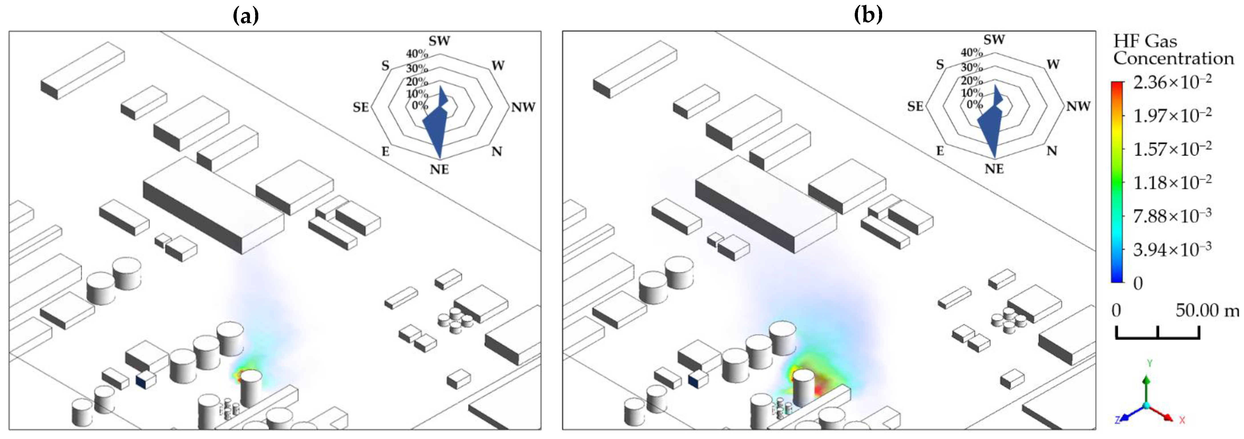
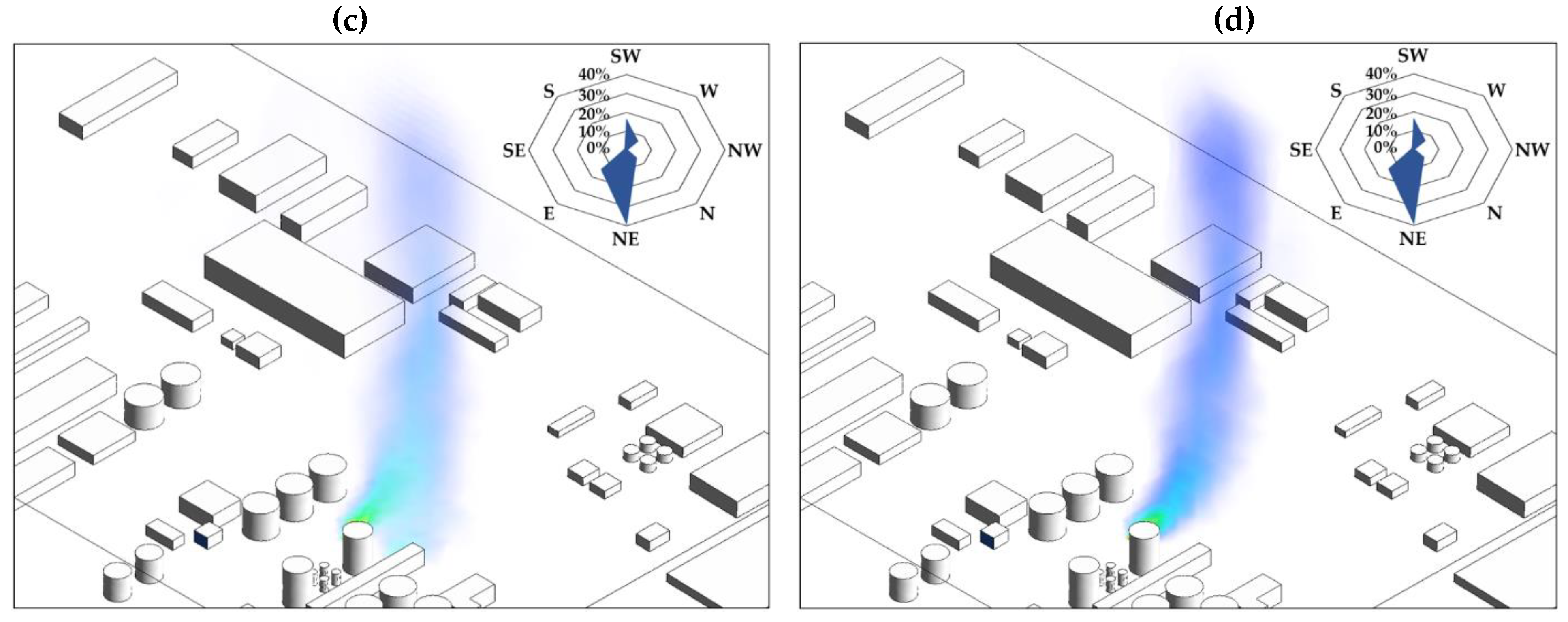
This study calculates the HF leakage diffusion process when the wind speed is 0, 1, 2, 4, and 6 m/s. In the calculation results, the phenomena at wind speeds of 1 m/s and 4 m/s are very typical. Figure 1 and Figure 2 show the three-dimensional concentration distribution changes of the HF diffusion process under these two conditions. As shown in Figure 1, when the wind speed is 1 m/s, HF diffuses in all directions after leaking, forming a planar influence zone. The closer to the leak hole, the higher the HF concentration. The closer to the bottom of the buildings, the higher the HF concentration. When the wind speed is 4 m/s, the three-dimensional concentration distribution changes of HF are shown in Figure 2. After HF leaks, it spreads to the downward wind direction and forms a band-shaped influence zone at 420 s. The closer to the leak hole, the higher the HF concentration. However, compared with the wind speed of 1 m/s, HF no longer accumulates at the bottom of buildings near the leak hole, but spreads far away.
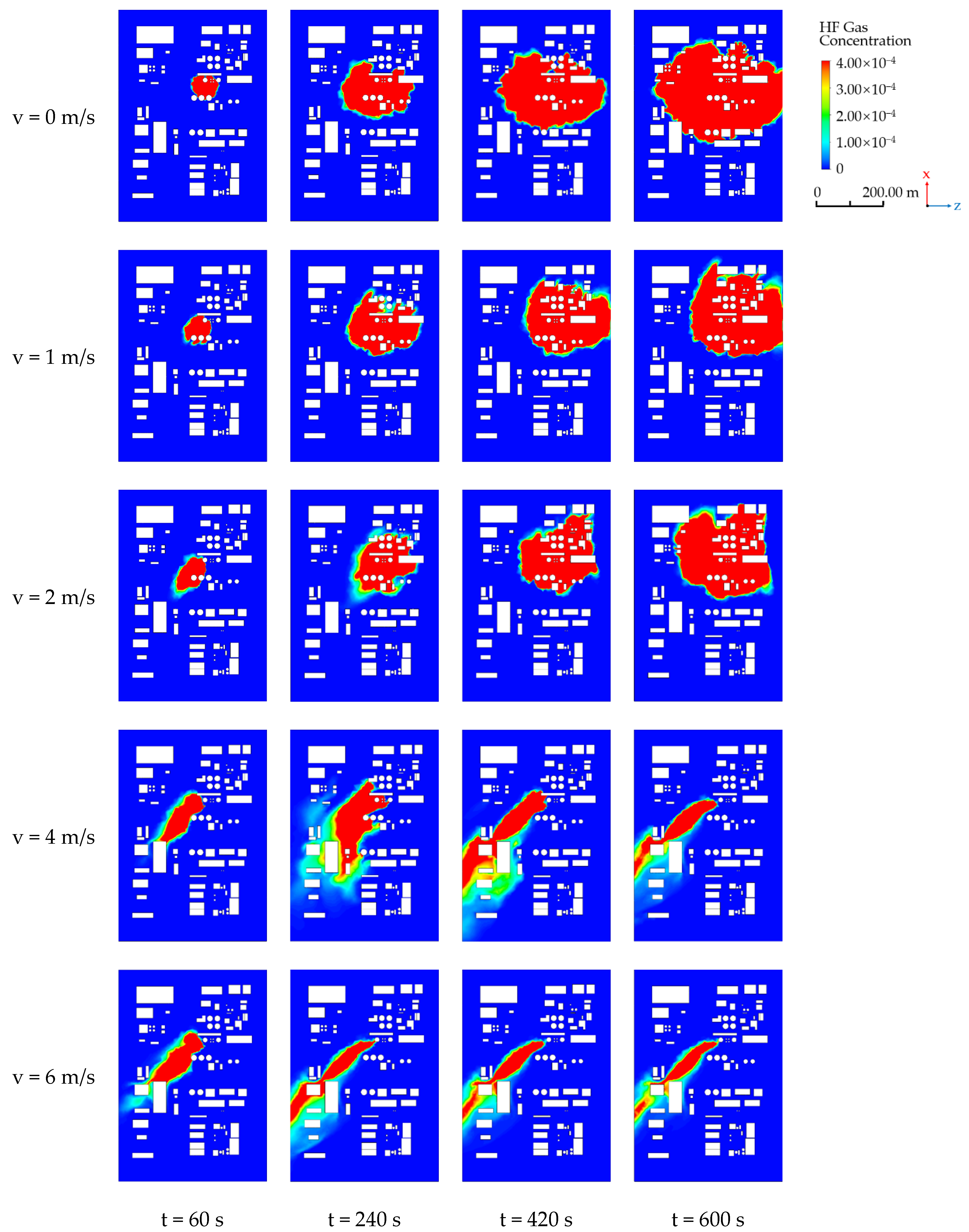
To accurately understand the harmful effects of HF on humans, this study simulates the diffusion of HF at a height of 1.8 m (1.8 m is the most common height for workers in the fluorine chemical plant) under different wind speeds. The results are shown in Figure 3. In a no-wind environment, the leaked HF spreads more evenly in all directions. The denser the buildings, the slower the dispersion rate. After 240 s, the distance that HF disperses in the z-axis direction is greater than the distance that it diffuses in the x-axis direction. When the wind speed is 1–2 m/s, the HF diffusion law is less affected by the wind, which is similar to the outcome of the no-wind environment. Due to the blocking effect of dense buildings, HF tends to disperse in the upward wind direction after 240 s. When the wind speed is 4–6 m/s, the wind speed has a greater effect on the diffusion of HF. HF forms a band-shaped area in the downwind dispersion process, and the greater the wind speed, the narrower the band area.

3.2. The Changing Law of Hazardous Areas at Different Heights

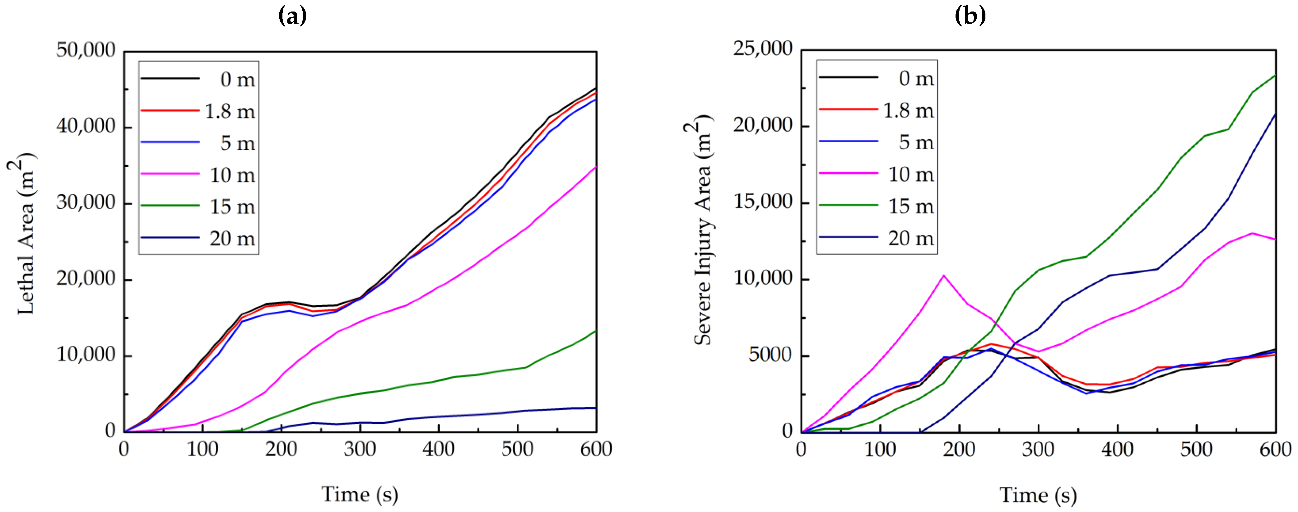
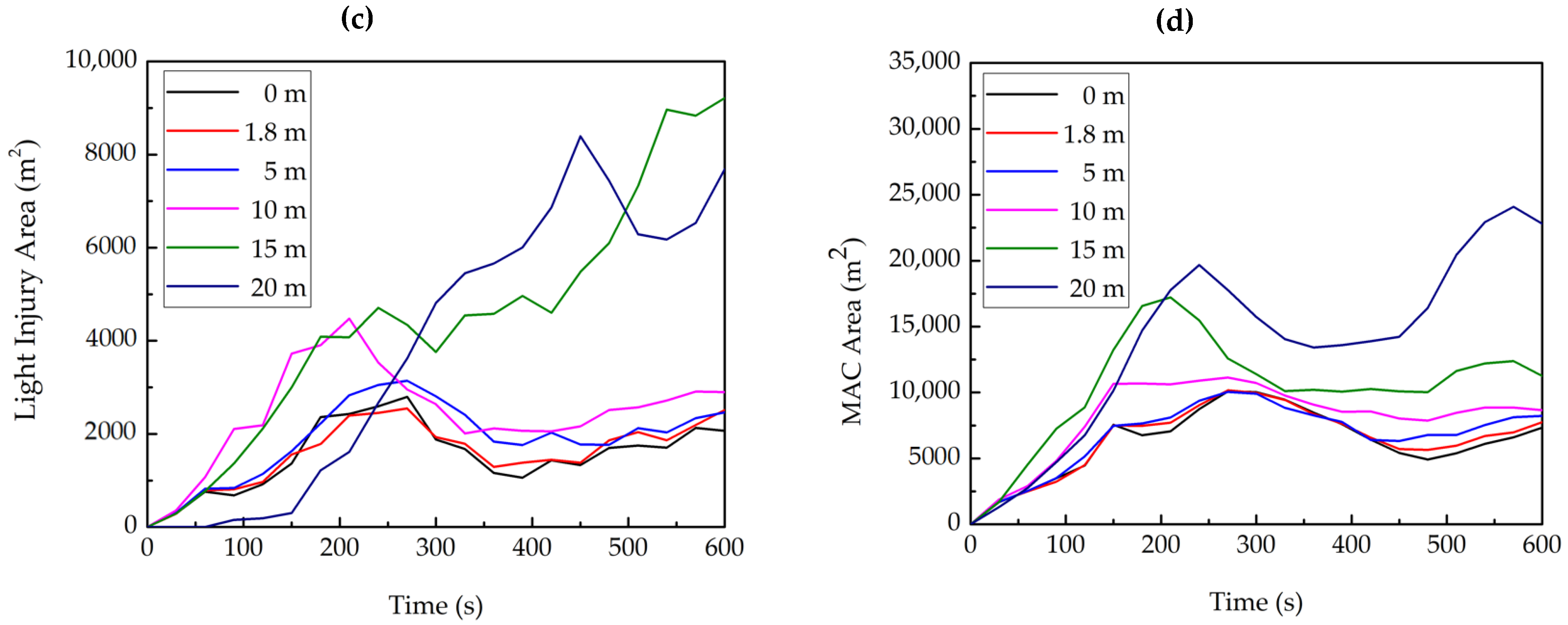
To analyze the effect of height on hazardous areas, the changes in four kinds of hazardous areas at heights of 0 m, 1.8 m, 5 m, 10 m, 15 m, and 20 m when the wind speed is 2 m/s are calculated, respectively. The calculation results are shown in Figure 4.
Figure 4a shows that when the time is 600 s, the lethal areas at heights of 0 m, 1.8 m, 5 m, 10 m, 15 m, and 20 m are 45,211 m2, 44,617 m2, 43,751 m2, 34,902 m2, 13,331 m2, and 3202 m2, respectively. When the height is less than 5 m, the lethal areas change little with the height. When the height is more than 5 m, the lethal areas decrease significantly with an increase in height.
Figure 4b,c show that when the time is 600 s, the severe injury areas at heights of 0 m, 1.8 m, 5 m, 10 m, 15 m, and 20 m are 5458 m2, 5088 m2, 5294 m2, 12,612 m2, 23,378 m2, and 20,895 m2. The light injury areas are 2065 m2, 2514 m2, 2463 m2, 2901 m2, 9212 m2, and 7689 m2. When the height is less than 5 m, the change in the severe and light injury areas is like that of the lethal areas. When the height is more than 5 m, their areas fluctuate greatly, but the changing trend also increases first and then decreases with an increase in the height.
Figure 4d shows that when the time is 600 s, the MAC areas at heights of 0 m, 1.8 m, 5 m, 10 m, 15 m, and 20 m are 7343 m2, 7751 m2, 8219 m2, 8668 m2, 11,252 m2, and 22,806 m2. When the height is less than 5 m, the changing trend of the MAC areas is like that of the other kinds of hazardous areas. When the height is more than 5 m, the MAC areas will increase significantly as the height increases.

3.3. The Changing Law of Hazardous Areas under Different Wind Speeds

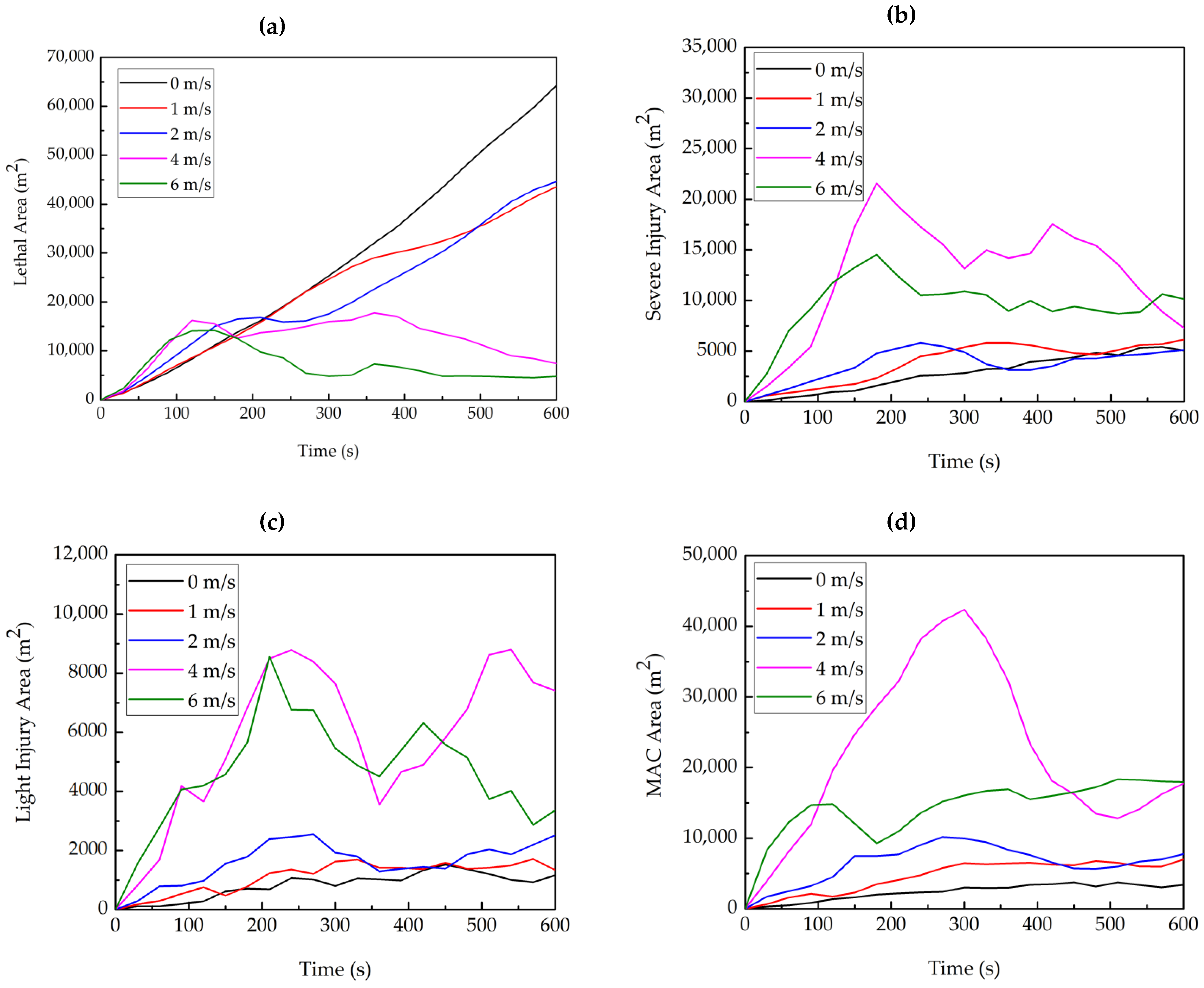
To study the effect of wind speed on hazardous areas, the changes of four kinds of hazardous areas at the height of 1.8 m when the wind speed is 0 m/s, 1 m/s, 2 m/s, 4 m/s, and 6 m/s are, respectively, analyzed. The results are shown in Figure 5.
When the wind speed is 0–2 m/s, the growth rate of the four hazardous areas is relatively flat, which is due to the uniform diffusion of HF in all directions after leakage at low wind speeds. The reason for the small fluctuation is that the dense buildings on the dispersion path block the HF. When the wind speed is 4–6 m/s, four hazardous areas fluctuate greatly. This is because HF spreads in the downward wind direction in a band shape at high wind speeds, which can be greatly affected by the wind.
Figure 5a shows that in 0–150 s, the greater the wind speed, the larger the lethal area. This is because, at the initial stage of diffusion, the wind transmits a large amount of high-concentration HF to the fluorine chemical plant area. The greater the wind speed, the faster the transmission speed. In 150–500 s, the greater the wind speed, the smaller the lethal area. When the wind speed is 0–2 m/s, the largest lethal area is 887.13% larger than that when the wind speed is 4–6 m/s. The reason for this difference is that in the middle and late periods of dispersion, the greater the wind speed, the greater the dilution effect on HF. After 500 s, due to the blocking effect of dense buildings on the dispersion path, the size relationship of the lethal area under different wind speeds is unstable.
According to Figure 5b–d, the greater the wind speed, the larger the severe injury area, the light injury area, and the MAC area. This is because when the wind speed is 0–2 m/s, the HF spreads uniformly in all directions in a planar shape, and the main body of the planar shape is the lethal area. The severe injury, light injury, and MAC areas are ring-shaped surrounding the lethal area. When the wind speed is 4–6 m/s, the lethal concentration of HF forms a band-shaped area. The greater the wind speed, the narrower the band-shaped area, the smaller the lethal area, and the larger the severe injury area, light injury area, and MAC area.
When the wind speed is 4–6 m/s, the changes in the severe injury area, the light injury area, and the MAC area are extremely unstable. This is because greater wind speeds have greater disturbance to HF diffusion, and dense buildings on the dispersion path have a blocking effect on it.

4. Conclusions

In this paper, CFD simulation software was used to predict the process and consequences of an HF leakage accident in the fluorine chemical plant. The diffusion law of HF under different wind speeds was studied. After fully considering the injury effect of HF on the human body, the affected area was divided into lethal area, severe injury area, light injury area, and MAC area. The effects of wind speed and height on hazardous areas were discussed. The main conclusions can be drawn as follows:
  • When the wind speed is less than 2 m/s, HF diffuses in all directions in a planar shape. When the wind speed is greater than 4 m/s, HF spreads in a downward wind direction in a band. The greater the wind speed, the greater the effect on HF diffusion.
  • When the wind speed is 2 m/s and the height is less than 5 m, the change in hazardous areas is almost independent of the height. At 600 s, the lethal area fluctuates within 43,751–45,211 m2, the severe injury area fluctuates within 5088–5458 m2, the light injury area fluctuates within 2065–2514 m2, and the MAC area fluctuates within 7343–8219 m2. When the height is greater than 5 m, as the height increases, the lethal area gradually decreases, the MAC area gradually increases, and the severe and light injury areas first increase and then decrease.
  • When the height is 1.8 m and the wind speed is 0–2 m/s, the growth rate of hazardous areas is flat. When the wind speed is 4–6 m/s, the hazardous areas fluctuate greatly. The reason for this difference is that at low wind speeds, HF spreads uniformly in all directions. However, under high wind speeds, HF diffuses in a band shape. The severe injury area, light injury area, and MAC area increase with the increase in wind speed. For the lethal area, the area increases with the increase in wind speed in the range of 0–150 s and decreases with the increase in wind speed in the range of 150–500 s.

Author Contributions

Conceptualization, S.C. and Z.Z.; methodology, S.C. and Z.Z.; software, S.C.; validation, S.C. and Z.Z.; formal analysis, S.C. and Z.Z.; investigation, S.C., Y.M. and L.Z.; resources, Z.Z. and Y.Z.; data curation, S.C.; writing—original draft preparation, S.C.; writing—review and editing, Z.Z., T.W. and S.W.; visualization, S.C., Y.M. and L.Z.; supervision, Z.Z. and Y.Z.; project administration, Z.Z.; funding acquisition, Z.Z. All authors have read and agreed to the published version of the manuscript.

Funding

This research was funded by the National Key Research and Development Program of China (Grant No. 2018YF0808600) and the National Natural Science Foundation of China (NNSFC) (Grant No. 11802160).

Institutional Review Board Statement

Not applicable.

Informed Consent Statement

Not applicable.

Data Availability Statement

All data included in this study are available upon request by contact with the corresponding author.

Conflicts of Interest

The authors declare no conflict of interest.

References

  1. Braun, J.; Stoss, H.; Zober, A. Intoxication following the inhalation of hydrogen fluoride. Arch. Toxicol. 1984, 56, 50–54. [Google Scholar] [CrossRef]
  2. Peters, D.; Miethchen, R. Symptoms and treatment of hydrogen fluoride injuries. J. Fluor. Chem. 1996, 79, 161–165. [Google Scholar] [CrossRef]
  3. Rhodes, C.S. Effects of fluorides in animals. Can. Vet. J. 1974, 16, 150. [Google Scholar]
  4. Stevens, D.P.; McLaughlin, M.J.; Alston, A.M. Phytotoxicity of hydrogen fluoride and fluoroborate and their uptake from solution culture by lycopersicon esculentum and avena sativa. Plant Soil 1998, 200, 175–184. [Google Scholar] [CrossRef]
  5. Yang, S.; Jeon, K.; Kang, D.; Han, C. Accident analysis of the gumi hydrogen fluoride gas leak using CFD and comparison with post-accidental environmental impacts. J. Loss Prev. Process Ind. 2017, 48, 207–215. [Google Scholar] [CrossRef]
  6. Ermak, D.L.; Chan, S.T.; Morgan, D.L.; Morris, L.K. A comparison of dense gas dispersion model simulations with burro series LNG spill test results. J. Hazard. Mater. 1982, 6, 129–160. [Google Scholar] [CrossRef]
  7. Koopman, R.P.; Cederwall, R.T.; Ermak, D.L.; Goldwire, H.C.; Hogan, W.J.; Mcclure, J.W.; Mcrae, T.G.; Morgan, D.L.; Rodean, H.C.; Shinn, J.H. Analysis of burro series 40-m3 LNG spill experiments. J. Hazard. Mater. 1982, 6, 43–83. [Google Scholar] [CrossRef]
  8. Morgan, D.L., Jr. Dispersion phenomenology of LNG vapor in the burro and coyote LNG spill experiments. J. Heat Transf. 1987, 109, 952–960. [Google Scholar] [CrossRef]
  9. Rodean, H.C. Effects of a spill of LNG on mean flow and turbulence under low wind speed, slightly stable atmospheric conditions. In Atmospheric Dispersion of Heavy Gases and Small Particles; Ooms, G., Tennekes, H., Eds.; Springer: Berlin/Heidelberg, Germany, 1983; pp. 157–166. [Google Scholar]
  10. Sklavounos, S.; Rigas, F. Simulation of coyote series trials—Part I: CFD estimation of non-isothermal LNG releases and comparison with box-model predictions. Chem. Eng. Sci. 2006, 61, 1434–1443. [Google Scholar] [CrossRef]
  11. Rigas, F.; Sklavounos, S. Simulation of coyote series trials—Part II: A computational approach to ignition and combustion of flammable vapor clouds. Chem. Eng. Sci. 2006, 61, 1444–1452. [Google Scholar] [CrossRef]
  12. Puttock, J.S.; Colenbrander, G.W. Thorney island data and dispersion modelling. J. Hazard. Mater. 1985, 11, 381–397. [Google Scholar] [CrossRef]
  13. Davies, M.E.; Singh, S. Thorney island: Its geography and meteorology. J. Hazard. Mater. 1985, 11, 91–124. [Google Scholar] [CrossRef]
  14. Mcquaid, J. Design of the thorney island continuous release trials. J. Hazard. Mater. 1987, 16, 1–8. [Google Scholar] [CrossRef]
  15. Hartwig, S. Improved understanding of heavy gas dispersion due to the analysis of the thorney island trials data. J. Hazard. Mater. 1985, 11, 417–423. [Google Scholar] [CrossRef]
  16. Brighton, P.W.M.; Prince, A.J. Overall properties of the heavy gas clouds in the thorney island phase II trials. J. Hazard. Mater. 1987, 16, 103–138. [Google Scholar] [CrossRef]
  17. Havens, J.A.; Schreurs, P.J.; Spicer, T.O. Analysis and simulation of thorney island trial 34. J. Hazard. Mater. 1987, 16, 139–148. [Google Scholar] [CrossRef]
  18. Puttock, J.S.; Blackmore, D.R.; Colenbrander, G.W. Field experiments on dense gas dispersion. J. Hazard. Mater. 1982, 6, 13–41. [Google Scholar] [CrossRef]
  19. Havens, J. Review of dense gas dispersion field experiments. J. Loss Prev. Process Ind. 1992, 5, 28–41. [Google Scholar] [CrossRef]
  20. Hajji, Y.; Jouini, B.; Bouteraa, M.; Elcafsi, A.; Belghith, A.; Bournot, P. Numerical study of hydrogen release accidents in a residential garage. Int. J. Hydrogen Energy 2015, 40, 9747–9759. [Google Scholar] [CrossRef]
  21. Kim, E.; Park, J.; Cho, J.H.; Moon, I. Simulation of hydrogen leak and explosion for the safety design of hydrogen fueling station in korea. Int. J. Hydrogen Energy 2013, 38, 1737–1743. [Google Scholar] [CrossRef]
  22. Malakhov, A.A.; Avdeenkov, A.V.; Toit, M.H.; Bessarabov, D.G. CFD simulation and experimental study of a hydrogen leak in a semi-closed space with the purpose of risk mitigation. Int. J. Hydrogen Energy 2020, 45, 9231–9240. [Google Scholar] [CrossRef]
  23. Zhou, N.; Cui, W.; Wang, K.; Zhao, H. Numerical simulation analysis of dangerous heavy gas leakage and diffusion. Adv. Mater. Res. 2013, 726–731, 1354–1357. [Google Scholar] [CrossRef]
  24. Tauseef, S.M.; Rashtchian, D.; Abbasi, S.A. CFD-based simulation of dense gas dispersion in presence of obstacles. J. Loss Prev. Process Ind. 2011, 24, 371–376. [Google Scholar] [CrossRef]
  25. Fiates, J.; Santos, R.R.C.; Neto, F.F.; Francesconi, A.Z.; Simoes, V.; Vianna, S.S.V. An alternative CFD tool for gas dispersion modelling of heavy gas. J. Loss Prev. Process Ind. 2016, 44, 583–593. [Google Scholar] [CrossRef]
  26. Wang, D.; Jiang, X.; Ou, Y.; Zhou, J. Numerical simulation analysis on hazardous area of oil gas leakage and dispersion in underground fuel depot. Adv. Mater. Res. 2013, 827, 220–223. [Google Scholar] [CrossRef]
  27. Dadashzadeh, M.; Khan, F.; Abbassi, R.; Hawboldt, K. Combustion products toxicity risk assessment in an offshore installation. Process Saf. Environ. Prot. 2014, 92, 616–624. [Google Scholar] [CrossRef]
  28. Souza, A.O.; Luiz, A.M.; Neto, A.T.; Araujo, A.C.; Silva, H.B.; Silva, S.K.; Alves, J.J. A new correlation for hazardous area classification based on experiments and CFD predictions. Process Saf. Prog. 2019, 38, 21–26. [Google Scholar] [CrossRef] [Green Version]
  29. Barros, P.L.; Luiz, A.M.; Nascimento, C.A.; Neto, A.T.; Alves, J.J. On the non-monotonic wind influence on flammable gas cloud from CFD simulations for hazardous area classification. J. Loss Prev. Process Ind. 2020, 68, 104278. [Google Scholar] [CrossRef]
  30. Pontiggia, M.; Landucci, G.; Busini, V.; Derudi, M.; Alba, M.; Scaioni, M.; Bonvicini, S.; Cozzani, V.; Rota, R. CFD model simulation of LPG dispersion in urban areas. Atmos. Environ. 2011, 45, 3913–3923. [Google Scholar] [CrossRef]
  31. Jones, W.P.; Launder, B.E. The prediction of laminarization with a two-equation model of turbulence. Int. J. Heat Mass Transf. 1972, 15, 301–314. [Google Scholar] [CrossRef]
  32. Shih, T.H.; Liou, W.W.; Shabbir, A.; Yang, Z.; Zhu, J. A new k-ϵ eddy viscosity model for high reynolds number turbulent flows. Comput. Fluids 1995, 24, 227–238. [Google Scholar] [CrossRef]
  33. Launder, B.E.; Reece, G.J.; Rodi, W. Progress in the development of a reynolds-stress turbulence closure. J. Fluid Mech. 1975, 68, 537–566. [Google Scholar] [CrossRef] [Green Version]
  34. Blocken, B.; Stathopoulos, T.; Saathoff, P.; Wang, X. Numerical evaluation of pollutant dispersion in the built environment: Comparisons between models and experiments. J. Wind Eng. Ind. Aerod. 2008, 96, 1817–1831. [Google Scholar] [CrossRef] [Green Version]
  35. Siddiqui, M.; Jayanti, S.; Swaminathan, T. CFD analysis of dense gas dispersion in indoor environment for risk assessment and risk mitigation. J. Hazard. Mater. 2012, 209–210, 177–185. [Google Scholar] [CrossRef]
  36. Chen, Y.H. Analysis of hazardous and harmful factors of hydrogen fluoride leakage and evaluation of poisoning model. Petrochem. Saf. Environ. Prot. Technol. 2010, 26, 19–21. (In Chinese) [Google Scholar]
  37. National Health Commission of the People’s Republic of China. Occupational Exposure Limits for Hazardous Agents in the Workplace—Part 1: Chemical Hazardous Agents; GBZ 2.1-2019; National Health Commission of the People’s Republic of China: Beijing, China, 2019; p. 11. (In Chinese)
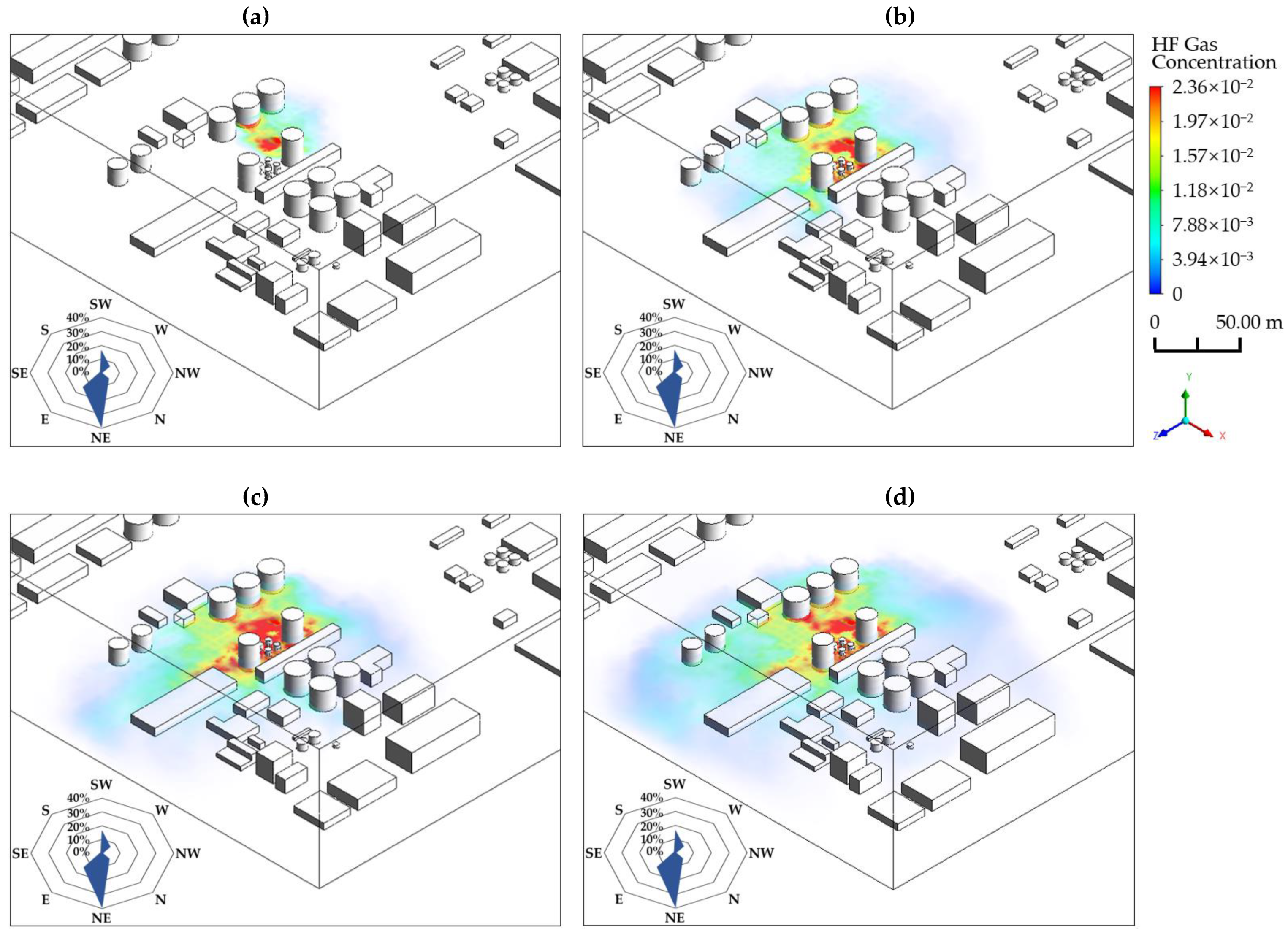
Figure 1. Changes in hydrogen fluoride (HF) three-dimensional concentration distribution with time when the wind speed is 1 m/s (the x-axis represents the north direction, and the z-axis represents the east direction): (a) t = 60 s; (b) t = 240 s; (c) t = 420 s; (d) t = 600 s.
Processes 09 01545 g001
Figure 2. Changes in HF three-dimensional concentration distribution with time when the wind speed is 4 m/s: (a) t = 60 s; (b) t = 240 s; (c) t = 420 s; (d) t = 600 s.
Processes 09 01545 g002aProcesses 09 01545 g002b
Figure 3. Changes in HF concentration distribution with time at 1.8 m height under different wind speeds (The red area is the lethal area).
Processes 09 01545 g003
Figure 4. Changes in hazardous areas with time at different heights when the wind speed is 2 m/s: (a) lethal area; (b) severe injury area; (c) light injury area; (d) maximum allowable concentration area (MAC area).
Processes 09 01545 g004aProcesses 09 01545 g004b
Figure 5. Changes in hazardous areas with time under different wind speeds at a height of 1.8 m: (a) lethal area; (b) severe injury area; (c) light injury area; (d) maximum allowable concentration area (MAC area).
Processes 09 01545 g005
Table 1. Goldfish 2, 3 experiment information.
Spill Rate
(m3/s)
Gas Density
(kg/m3)
Air Density
(kg/m3)
Wind Speed
(m/s)
Ambient Temperature (°C)Leak Source Diameter (m)Leak Source Height
(m)
GF20.0112.141.014.2036.00.0252.00
GF30.0112.201.045.4026.50.0252.00
Table 2. Comparison of simulation and experiment results.
Simulation Results
(×10−5 kg/m3)
Experiment Results
(×10−5 kg/m3)
Relative Error
GF22.35871.939621.61%
GF32.20211.859618.42%
Table 3. Division and basis of hazardous areas.
HF Concentration
(×10−6 kg/m3)
DescriptionHazardous Area Definition
400Acute poisoning deathLethal area
100Can only tolerate 1 minSevere injury area
50Skin and mucous membrane irritationLight injury area
2Maximum allowable concentration in occupational exposure scenariosMaximum allowable concentration area (MAC area)
Publisher’s Note: MDPI stays neutral with regard to jurisdictional claims in published maps and institutional affiliations.