Article

The Long-Term Mitigating Effect of Horizontal Ground-Source Heat Exchangers on Permafrost Thaw Settlement

1
Department of Civil Engineering, University of Manitoba, Winnipeg, MB R3T 5V6, Canada
2
Department of Civil, Geological and Mining Engineering (CGM), Polytechnique Montréal, Montréal, QC H3C 3A7, Canada
3
KGS Group, Winnipeg, MB R3T 5P4, Canada
*
Author to whom correspondence should be addressed.
Processes 2021, 9(9), 1636; https://doi.org/10.3390/pr9091636
Submission received: 23 June 2021 / Revised: 23 August 2021 / Accepted: 28 August 2021 / Published: 10 September 2021
(This article belongs to the Special Issue Numerical Modeling in Civil and Mining Geotechnical Engineering)

Abstract

:
This study investigated the long-term effect of horizontal Ground-Source Heat Exchangers (GSHEs) on mitigating permafrost thaw settlement. In the conceptual system, a fan coil was used to chill the recirculating fluid in the linear High-Density Polyethylene (HDPE) ground loop system. A fully coupled thermo-hydro-mechanical finite element framework was employed to analyze multiphysics processes involved in the thaw settlement phenomenon. To investigate the sustainability of the system, a period of 50 years was simulated. Two operational modes were defined: one without and the other with HDPE. Different heat carrier velocities and inlet temperatures, and heat exchanger depths were examined to explore their effects on the thaw settlement rate. It was concluded that the proposed system can effectively alleviate the predicted permafrost thaw settlement over the study period. Moreover, the heat carrier temperature was found to have a prominent impact on the thaw settlement rate amongst other parameters.

1. Introduction

Permafrost is ground (solid, sediment, rock) that remains frozen for at least two consecutive years [1]. Over the last 30 years, the mean annual temperature in the Arctic has risen at a rate of 0.54 °C per decade, a triple increase compared to the global average temperature [2]. This rapid increase in air temperature is leading the permafrost to thaw at an unprecedented rate. Permafrost thaw settlement as a consequence of climate change causes considerable damages to the northern infrastructures. Therefore, the assessment of permafrost thaw settlement is of paramount importance in investigating the resiliency of northern infrastructures and selecting the most sustainable mitigation strategies.
Permafrost thaw settlement involves heat and mass transfer, pore water pressure dissipation, deformation, and strength evolution. It is indeed a complex multiphysics process involving thermal (T), hydraulic (H), and mechanical (M) analyses, which is hereafter referred to as thermo-hydro-mechanical (THM) analysis [3]. The first complete thaw consolidation theory was introduced and developed by Morgenstern and Nixon [4], where they formulated the settlement based on the small-strain consolidation theory. However, the proposed model cannot be applied to an ice-rich permafrost where the soil undergoes large strain settlements [5]. Foriero and Ladanyi [6] overcame this shortcoming by developing a large-strain consolidation theory which allows finite strains and considers the variation of hydraulic conductivity and compressibility during the consolidation process.
Besides the effort in modelling the permafrost thaw settlement process, numerous climate change adaptation strategies and mitigation solutions have been developed in the last few decades. These techniques are generally classified into three main groups: (i) limiting the heat transfer from the atmosphere into permafrost (e.g., providing shades, vegetation, etc.), (ii) extracting heat to cool down permafrost, and (iii) reinforcing the infrastructure against settlement [7]. Among a wide range of permafrost stabilization methods, thermosiphons have been most widely used due to their simple structure, high efficiency, and low fabrication costs [8]. This technology comes under the second category that aims to extract heat out the system and lessen the temperature of degrading permafrost. Chen et al. [9] studied the effect of thermosiphons on reducing thaw settlement of an embankment built on a sandy permafrost. They found that the thermosiphon performance in mitigating thaw settlement highly depends on the mean annual air temperature.
Ground-Source Heat Exchangers (GSHEs) with a similar function of heat extraction to thermosiphons have been traditionally used for heat energy supply and the heating/cooling demand of buildings. However, their effects on permafrost stabilization have rarely been studied. Fontaine et al. [10] presented a new analytical model to study the effect of a spiral-shaped horizontal ground heat exchanger on permafrost stabilization. However, their model overestimated the summer ground temperature and thaw depth. Only a short-term (5 years) analysis was carried out and the long-term performance of the GSHE system was not investigated.
In this paper, the effectiveness of a horizontal GSHE system as a long-term and sustainable solution for permafrost stabilization was evaluated. The study site was located in a wastewater lagoon facility in Ross River, Yukon, Canada, where the huge heat leakage from the wastewater was expected to induce permafrost degradation and significant thaw settlement. The proposed system consisted of a horizontal closed-loop system that circulates an anti-freeze coolant to cool down the ground and mitigate the thawing permafrost beneath the base of the lagoon.

2. Materials and Methods

2.1. Study Area

This research was carried out on a freeze-back system at the Ross River’s wastewater lagoon in a permafrost rich area, Yukon, Canada (Figure 1a). The Ross River community (61°32′, 132°35′) is located within the zone of extensive discontinuous and mostly warm permafrost. The present wastewater lagoon for the community is located to the west of the community, approximately 700 m south of the Pelly River. The lagoon system was constructed in fall 2017 and consisted of two cells—a primary cell and a secondary cell with the base dimensions of 75 m × 15 m and 75 m × 35 m, respectively, to provide continuous treatment efficiency and ensure no raw, untreated influent discharges. The lagoon base was placed 3 m below the original ground level through excavation, and the maximum lagoon depth was 3 m, as well. The wastewater lagoon system was designed for the wastewater production per capita of 110 L/day/person, the annual wastewater production of 17,000 m3/year, and 10-month storage volume of 14,000 m3/year [11]. The 3 m depth of excavation for the construction of the wastewater lagoon exposed the underlying permafrost to a downward heat flux from the lagoon base. The lagoon heat regime comes from the solar radiation into the wastewater in the lagoon, leading the lagoon to maintain a temperature above the freezing temperature all year round. Lagoon operation will also impede seasonal freeze back within the active layer in the winter.
A geotechnical investigation [12] reported that the site stratigraphy consists of approximately 2 to 3 m of sandy gravel overlying a 3.2 to 4 m thick clayey silt layer. Ice lensing with a maximum thickness of 20 mm had been detected within the clayey silt. According to the field observation from the two boreholes of BH18-05 and BH18-06 (Figure 1b), the average permafrost layer started at 8 m below the original ground level and 5 m below the lagoon base, extending to 22 m in depth (Figure 1c). The investigation also reported that the water content was 8% and 30% in the sandy gravel and clayey silt layer, respectively.

2.2. Specification and Conceptual Model of the Proposed GSHE System

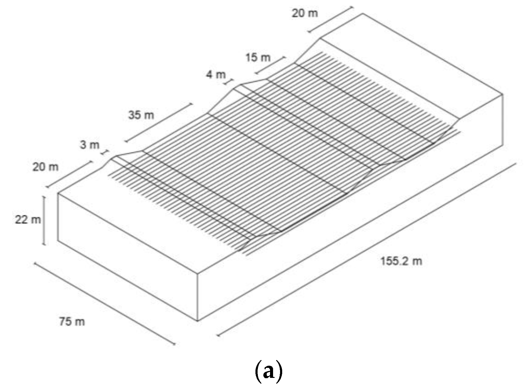
The studied GSHE system consisted of horizontal HDPE pipes, each 50 mm in diameter and 45 and 70 m long, which were horizontally placed 2 m away and 1.5 m below the lagoon’s base (4.5 m from the original ground level) under the primary and secondary cells, respectively (Figure 2a). Using the symmetry in the layout of the HDPE pipes, only one repeated block of the soil domain with five embedded heat exchangers (Figure 2b) was considered to decrease the computational time [13]. The coolant fluid was a 30% ethanol-water blend with a velocity and inlet temperature of 0.4 m/s and −5 °C, respectively. Different pipe burial depths, heat exchanger velocities, and temperatures were modelled to understand their effects on the efficiency of system. For this purpose, 3 different pipe depths (1.5, 2.5, and 3.5 m), 3 heat exchanger inlet velocities (0.2, 0.4, and 0.6 m/s) and 4 heat exchanger inlet temperatures (−1, −5, −10, and −15 °C) were tested. Due to the considerable lagoon heat flux and significant permafrost thaw rate, the GSHE system operated year round. Although the extracted geothermal heat can be pumped to nearby buildings, the heat recovery from the Ross River Lagoon was not used for residential or industrial buildings as they were not located within close distance to the lagoon. According to the field observation from BH18-05, the initial soil temperature (2019) was rather stable in permafrost at −0.2 °C and gradually increased in the shallower areas, reaching 8 °C at the ground surface.
The top boundary of the domain was in contact with the surrounding air and the lagoon base. Because of the exposure to the ambient air, a forced convective heat flux ( q a ) was applied to the parts of the top boundary exposed to the air. The boundary condition at the interface between the lagoon base and the soil was also defined by a convective heat flux ( q l ) [14]. The lagoon temperature varies with a rather sinusoidal pattern, starting from 4 °C in mid-winter to 20 °C in mid-summer [11].
In addition, a constant upward heat flux ( q b ) was assigned to the bottom of the domain to represent the geothermal heat flux that exists at the site. The sides of the domain were defined as adiabatic boundaries as shown in Figure 2c.
Mechanical boundary condition consisted of an overburden pressure equivalent to the weight of the wastewater under the lagoon’s full operational mode, applied on the lagoon’s bottoms and walls. To model the elastoplastic soil behavior, the initial stress was defined as the sum of the overburden pressure and the soil total stress (multiplied by lateral pressure coefficient at rest ( k 0 ) for the initial stress in the X-direction). The bottom of the domain was set to the fixed support and the domain’s sides were defined as roller support with a degree of freedom in the vertical direction. Darcy’s law was utilized to model the hydraulic boundaries and initial conditions. The bottom and sides of the domain were defined as no-flow boundaries and an initial hydrostatic pressure was assigned to the entire domain.
A series of 2D multiphysics finite element (FE) simulations of a GSHE system, including thermal analyses of heat exchangers and the THM process in foundation permafrost, was conducted in COMSOL Multiphysics v5.4 (COMSOL INC, Stockholm, Södermanland and Uppland, Sweden). Thaw settlement and possible frost heave (due to the seasonal freezing) were calculated based on a THM model which accounts for the evolution of strength, porosity, hydraulic conductivity, and pore water pressure during the freeze–thaw cycles. To eliminate unwanted effects of boundaries on the analysis and avoid erroneous results, different distances from the outermost dike edge, including 10, 20, and 30 m, and from the permafrost bottom level, including 0, 10 m, and 20 m, were examined (Figure 3). The thermal analysis showed that the model with a 20 m horizontal distance from the outermost dike edge and 0 m vertical distance from the permafrost bottom level resulted in consistent results in the permafrost temperature distribution even if larger distances were selected. The study period was 50 years, starting from 2019 and ending in 2069, with 15-day time intervals. To study the remedial effect of the proposed GSHE system in reducing thaw settlement, two scenarios were introduced: one without GHSEs and the other with GSHEs, and the results were compared.

2.3. Governing Equations

The thaw settlement phenomenon consists of different physics interacting with each other, including: (1) the porous nature of soil and its temperature-dependent physical and mechanical properties, (2) heat transfer mechanism in porous soil, (3) mechanical behavior of the thawing soil, and (4) heat and mass transfer mechanism of the pore fluid. To study the effectiveness of the GSHE on limiting the thaw settlement, the pipe flow and heat exchange (through its walls) must be coupled with the above-mentioned physics. Described in the following subsection.

2.3.1. Heat Transfer within Degrading Permafrost during Freeze–Thaw Cycle

Conductive Heat Transfer Considering Pore Water Phase Change

The transient heat conduction in the soil by considering the latent heat of pore water can be described as [13]:
C a p p T t + · q = Q
where T (K) is the soil temperature, Q (W/m3) is the heat source/sink, = ( x , y , z ) is the gradient operator, t (s) is time, and q (W/m2) is the conductive heat flux defined by Fourier’s law:
q = λ T
where (W/(m. K)) is the thermal conductivity of the saturated frozen medium. The term C_app is defined as the apparent heat capacity (J/(kg. K)), expressed as:
C a p p = 1 ρ ( ρ p h C p h L f ρ i θ i t )
where L f (kJ/kg) is the latent heat per unit mass of water, ρ (m/kg3) is the bulk density of the porous medium, ρ i (m/kg3) is the density of ice, and θ i is the volumetric fraction of ice in pores. The term ρ p h C p h (J/(m3. K)) denotes the volumetric heat capacity of the soil mixture which can be calculated by the sum of the volumetric heat capacity of each constituent of the saturated freezing medium (solid skeleton, water, and ice) multiplied by its volumetric fraction ( θ ) as follows:
ρ p h C p h = ρ s C s θ s + ρ w C w θ w + ρ i C i θ i
where s, w, and i denote solid skeleton, water, and ice, respectively. Similarly, thermal conductivity ( λ ) and the bulk density ( ρ ) of the saturated frozen soil mixture can be defined as Equations (5) and (6), respectively:
λ = ρ s θ s λ s + ρ w θ w λ w + ρ i θ i λ i
ρ = ρ s θ s + ρ w θ w + ρ i θ i
where ρ s , ρ w , and ρ i and λ s ,   λ w , and λ i are are the density and thermal conductivity of soil, water, and ice, respectively.

2.3.2. Mechanical Behavior of the Soil during Freeze–Thaw Cycles

Kinematic Formulation

The linearized form of Green–Lagrange strain tensor ( ε i j ) for infinitesimal deformations is formulated as:
ε i j = 1 2 ( u i , j + u j , i )
in which u i and u j are the displacement vector in the i and j direction, respectively.

Constitutive Model

The effective stress is defined as the difference between the total stress ( σ i j ) and the pore water pressure ( u ):
σ i j = σ i j α u δ i j
where α is the Biot coefficient.
The effective stress is averaged over the solid mineral particles and ice. The equation of equilibrium is formulated as:
σ j i , j + F i = 0
where F i is the body force.
The mass conservation principle is:
θ w t + ρ i ρ w θ i t + q w + ε v t = 0
where ε v is the volumetric strain and q w is water flux governed by Darcy’s law.
Pore ice ratio ( e i p ) as a key parameter in describing the behavior of the frozen soil [3] is introduced as:
e i p = V i V s
in which V i and V s are the pore ice and soil skeleton volume, respectively. Moreover, to describe the volumetric changes of the soil, specific volume is defined as follows:
υ = V V s = 1 + e
where, υ is the total volume of the soil and e is the void ratio. The mean effective stress ( p ) is defined as:
p = 1 3 σ k k           k = 1 , 2 , 3
where σ k k is the principal stresses of the effective stress tensor.
The changes in the void ratio (and thus specific volume) versus effective stress is non-linear over the range of stresses in practice [5,14]. Experimental studies demonstrated that this behavior can truly be captured by a semi-logarithm relationship, formulated as follows [5]:
υ = υ 0 λ ln p p r
where υ 0 is the specific volume at the reference pressure p r (MPa) and λ is the slope of the normally consolidation line (NCL) for unfrozen soil. The elastic changes of the specific volume in the unloading-reloading line (URL) is:
d υ e = κ d p p
where k is the slope of URL.
The increase in the soil strength is a function of pore ice ratio ( e i p ). The subsequent relationships for the slope of NCL and URL for frozen soil are:
λ f = λ exp ( α 1 e i p )
κ f = κ exp ( α 2 e i p )
where α 1 and α 2 are the soil constants [3]. Slopes λ and k for the unfrozen soil and λ f and k f for the frozen soil can be obtained from isotropic compression tests in a triaxial apparatus.
The pre-consolidation pressure increases during freezing process and reaches p 0 f for frozen soil which can be obtained from the following equation:
P 0 f p r = exp ( β e i p λ f κ f ) ( p 0 p r ) ( λ κ f λ f κ f )
where β is a function of p r which can be obtained from isotropic compression test in a triaxial apparatus.

Non-Isothermal Heat Transfer from Pipe Flow

In order to couple the heat transfer in a solid with the heat transfer from the pipe flow, the following differential energy equation must be satisfied [15]:
ρ A C a p p T t + ρ f A C p f v ¯ T = Δ A λ f T + ρ 2 d h | v ¯ | 3 + Q w a l l
where A is pipe cross section area (m2), C p f (J/kg. K) is the heat capacity of the fluid at constant pressure, v ¯ (m/s), T (K), and λ f (W/(m·K)) are the fluid velocity, temperature, and thermal conductivity, and d h (m) is the hydraulic diameter. The term Q w a l l (W/m3) is the external heat source/sink term through the pipe wall.

Convective Heat Flux

To model the seasonal temperature variation on the soil temperature, the below convective heat flux was assigned to the area of the top domain boundary with a contact to the ambient air:
Heat   Flux :   q t ( t ) = h c o n v ( a ) ( T a ( t ) T s ( t ) )
where h c o n v ( a ) (W/m2°C) is the convection heat transfer coefficient for the domain area exposed to the ambient air. T s (°C) is the ground surface temperature (calculated in each time step) and T a (°C) is the air temperature at the ground surface. The boundary conditions at the interface between the lagoon base and the ground surface are also defined by a convective heat flux, formulated as follows:
Heat   Flux :   q l ( t ) = h c o n v ( l ) ( T l ( t ) T s ( t ) )
where T l (°C) is the lagoon temperature and h c o n v ( l ) is the lagoon heat transfer coefficient. The wastewater lagoon bottom and walls are made of concrete. Since the value of the heat transfer coefficient for the concrete between wastewater and soil does not exist in the literature, in this study this value was quantified numerically using finite element analysis. The result of the stationary heat transfer analysis yielded 4.0 and 5.0 (W/m2°C), for the heat transfer coefficient of the inclined sides and horizontal bottom boundary, respectively.

2.4. Numerical Modeling

2.4.1. Soil Properties

Since no geotechnical laboratory tests had been conducted to determine the in situ soil properties of the site, the average values for clay/sandy soils [16] were considered, as given in Table 1. Other parameters including water, ice, and coolant fluid thermal properties were taken from previous studies [3,16]. The required parameters for modelling the heat transfer in a porous matrix and non-isothermal pipe flow are given in Table 2. In addition, the associated parameters of the thaw settlement for clayey soil are as follows: λ = 0.35, k = 0.07, p 0 = 650 MPa, α 1 = 0.4, α 2 = 1.8, p r = 0.1 MPa, and β = 0.18 [3].

2.4.2. Mesh Sensitivity Analysis

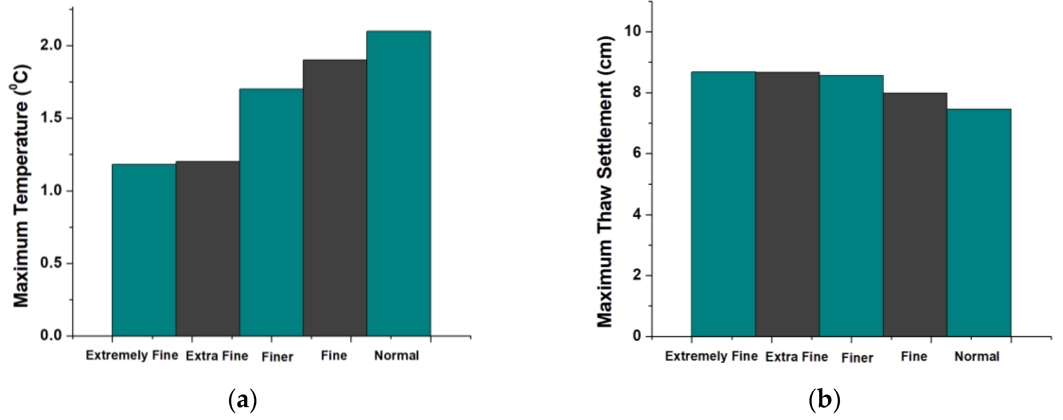
The triangular Lagrange finite elements were applied for the heat transfer, non-isothermal pipe models and solid mechanics [18]. The mesh consistency testing showed that the nodal distance associated with “extra fine” mesh in COMSOL Multiphysics resulted in consistent results in the maximum temperature and surface thaw settlement even if a smaller nodal distance was selected (Figure 4). Moreover, “extremely fine” meshing was assigned to the area close to the lagoon base and GSHEs to increase the precision in the analysis (Figure 5).

2.5. Model Validation

A laboratory test conducted by Wang et al. [19] on the settlement of the sandy clay, similar to Ross River soil stratigraphy, was used to verify the results of the numerical simulation. In this experiment, a cylindrical sandy clay sample with 100 mm diameter and 112.8 mm height was tested with a dry density of 1400 kg/m3 and 20.9% water content. The initial temperature of the sample was set to −1 °C and a simplified thermal boundary was defined on the top boundary as:
T t o p ( C ) = 5.0 sin ( 1.047 t + 1.57 )
where t (h) is time. In addition, a constant temperature of 1 °C was applied on the bottom boundary. The study period was 100 h with 30-min time intervals. Further information regarding the material, hydraulic, and mechanical properties of the tested frozen soil can be found in [19].
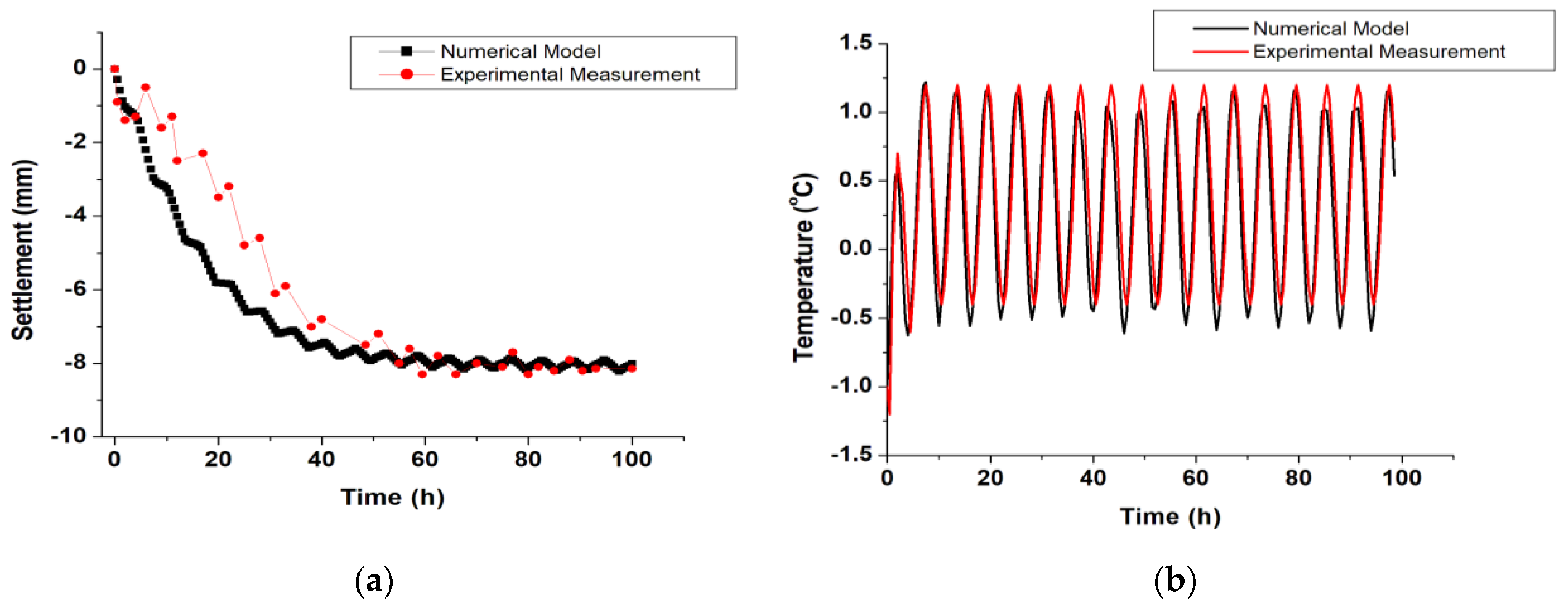
In a similar manner to the above laboratory experiment, a finite element simulation was carried out. The experimental and numerical results of the thaw settlement at the top domain and the temperature variation of a point at the depth of 6 cm, both located on the centerline, are plotted in Figure 6.
The maximum difference in the vertical thaw settlement between the experimental measurement and numerical results (Figure 6a) was 2.68 mm, which accounts for 2.68% of the initial height of the sample. In addition, the final settlement value (8 mm) was consistent in both numerical analysis and the lab test. The maximum difference in the temperature of the selected point was 0.54 °C after the 45th hour (Figure 6b). Given the marginal difference between the experimental measurement and the numerical model, a satisfactory level of accuracy was obtained. Therefore, the same numerical modelling procedure was implemented for estimating the long-term thaw settlement under the Ross River wastewater lagoon. The soil properties, model geometry, thermal boundaries, and study time were adjusted accordingly.

3. Results and Discussion

3.1. Thaw Settlement Due to the Lagoon Heat Flux and Climatic Conditions without Embedded GHSE System

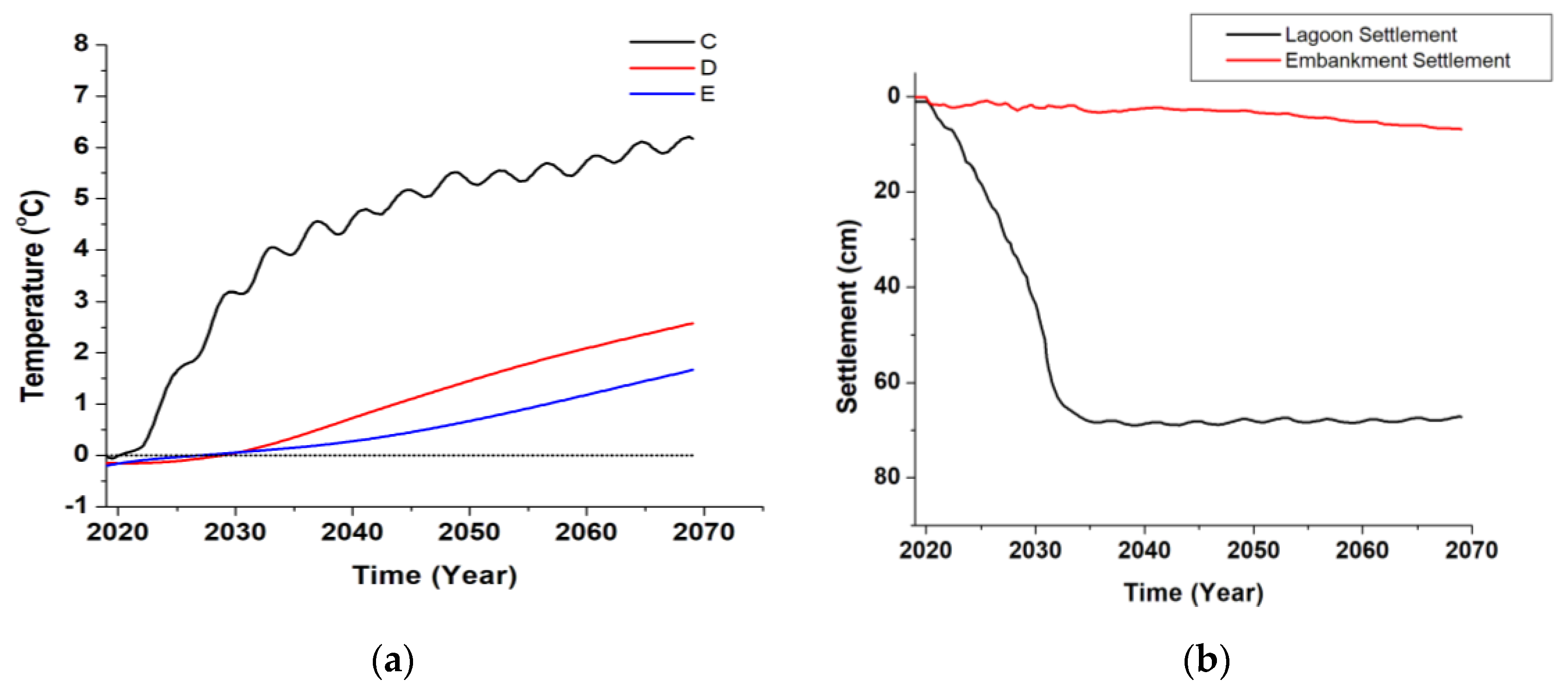
First, the temperature variation of different points at three depths were studied to investigate the thaw settlement. These three points were chosen at the depth of −5 (point C), −12 (point D), and −18 m (point E), which were representative of the top, middle, and bottom of the permafrost, respectively (Figure 7). The 50-year temperature variation of the selected points (Figure 8a) indicates that Point C, D, and E reached the above-freezing temperature after 1, 10, and 7 years, respectively. Thaw at point E took place earlier than point D due to the upward geothermal heat flux which existed at the model bottom.
Thaw settlement at the lagoon elevation and the embankment was studied comparing points A and B, respectively (Figure 8b). Uneven settlement is one of the main contributing factors in damaging the functionality of the wastewater lagoon. The results indicate that the thaw settlement under the wastewater lagoon was initiated immediately after the lagoon operation due to its heat leakage and reached 69 cm in 2034, a year in which all permafrost thawed.
The permafrost thaw settlement of the embankment gradually increased over the 50-year study time. Unlike the permafrost underneath the lagoon which would disappear by 2031, permafrost under the embankment thawed at a slower rate and some permafrost existed even after 50 years. The maximum embankment settlement was 6 cm in 2069, which was 63 cm less than that of lagoon at the end of the 50-year study period. The maximum difference in the settlement under the lagoon and the embankment was 66 cm in 2039. However, the difference in the thaw settlement of the lagoon and embankment decreased over time.

3.2. Effect of Horizontal GSHE System on Permafrost Preservation

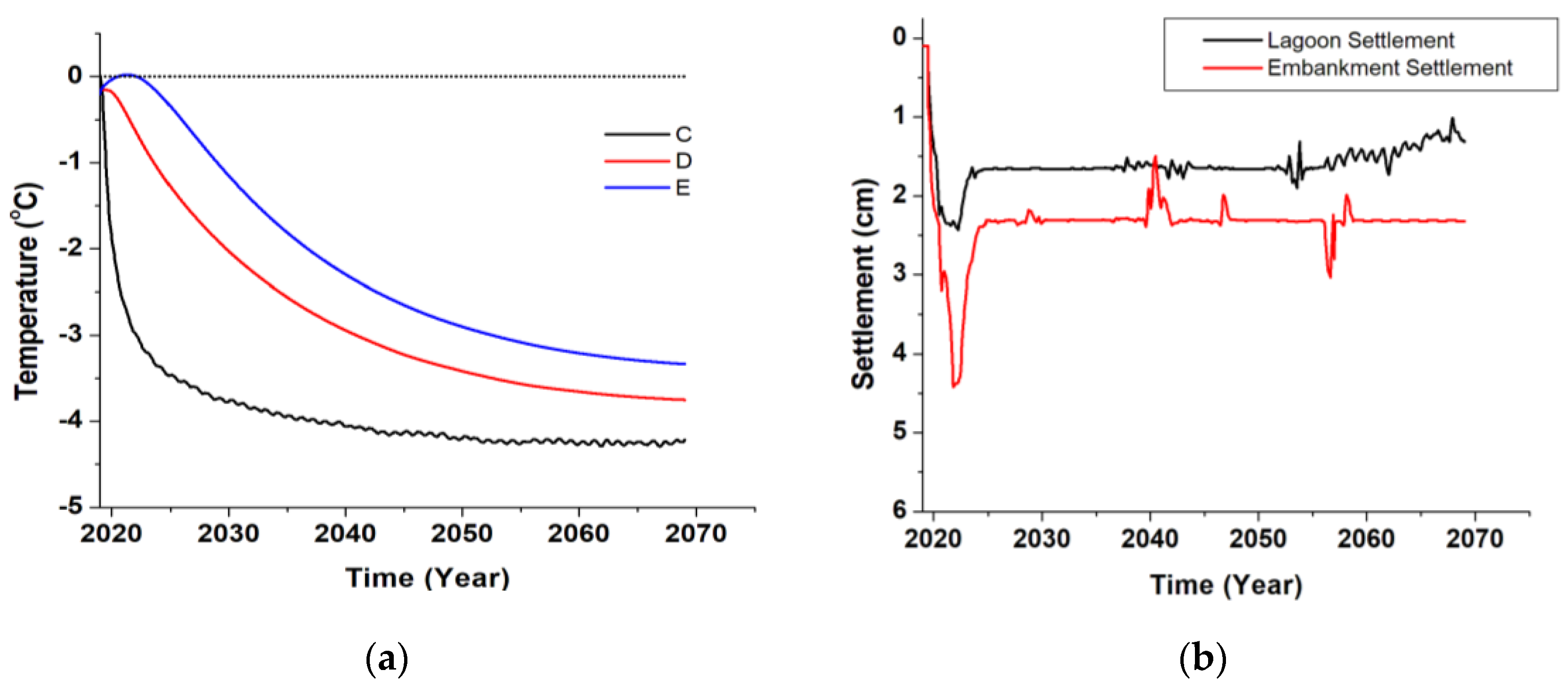
The horizontal HDPE heat exchangers were embedded within the domain to see the effect of GSHEs on the thaw settlement. Temperature variation of the three points illustrate that the GSHEs can considerably reduce the permafrost temperature at different points (Figure 9a). Using horizontal GSHEs maintained the temperature of points C and D in the freezing range throughout the 50-year study time. However, the temperature of point E (the furthest point to the pipes) rose to above zero by 2021 and it took the freezing effect of the pipes 2 years to neutralize the upward geothermal heat flux from the model bottom. As a result, by 2021 the lagoon and embankment underwent 2.4 and 4.4 cm thaw settlement, respectively, a 96% and 28% reduction in the maximum settlement compared to the case when no GSHE was used. The maximum difference in the thaw settlement between the lagoon and embankment also decreased by 97%. It should be noted that the thaw settlement of the embankment was greater than the lagoon due to being away from the GSHEs. Following that, the freezing effect of the pipes induced some level of heave in both lagoon and embankment. The heave in the lagoon was 0.8 cm by 2037, followed by a growth to a maximum of 1.3 cm by 2069 due to the combined effect of the lagoon temperature and GSHEs. The heave in the embankment surface was 2.3 cm and stayed almost constant with the exception of some fluctuations in 2041 and 2058. The induced heave compensated for the thaw settlement to some extent, resulting in the net settlement reaching 1.3 and 2.6 cm in the lagoon and embankment, respectively.

3.3. Effect of Operational Parameters of the Horizontal GSHE System on the Heat Extraction Power and Thaw Settlement

Analyzing different operational parameters given in Table 3 proved that these parameters have a significant impact on the heat extraction power and permafrost thaw settlement.
As expected, the heat extraction power increased when lower fluid inlet temperatures were used. Based on Equation (2), larger temperature gradient between the fluid coolant and the surrounding soil leads to higher heat transfer quantities. Conversely, the fastest coolant did not contribute to the highest heat extraction power and 1.4% decrease was observed when the fluid inlet velocity changed from 0.4 to 0.6 m/s. Similar to the inlet temperature, changing the burial depth resulted in significant variation of the heat extraction power and compared to 1.5 m burial depth, 32% and 41% reduction was observed with 2.5 and 3.5 m pipe burial depths. Deeper operational pipes were further from the lagoon heat flux and therefore they were exposed to smaller temperature gradient.
With regard to settlement, using a −5 °C coolant instead of −1 °C reduced the lagoon thaw settlement by 57%. Similarly, the embankment settlement decreased from 7.4 to 2.4 cm, and the maximum difference in the lagoon and embankment declined by 91%. Colder fluids with a temperature of −10 and −15 °C resulted in larger heave in the lagoon bottom which could initiate cracks in the wastewater facility. In the embankment, using −10 °C fluid temperature increased the settlement by 1.1 cm compared to −5 °C fluid. The smallest embankment settlement occurred when −15 °C fluid temperature was used. In light of the above, a heat carrier temperature of −5 °C provided the best results.
Changing the heat carrier inlet velocity from 0.4 to 0.2 m/s and from 0.4 to 0.6 m/s resulted in 0.3 and 0.2 cm increase in the final thaw settlement of the lagoon, respectively. Greater differences emerged in the embankment thaw settlement, where changing the fluid inlet velocity from 0.4 to 0.2 m/s resulted in a roughly 12-fold increase in the thaw settlement. Changing this parameter to 0.6 m/s resulted in a fourfold increase in the thaw settlement. A faster heat carrier passes the domain in a shorter time, so it loses the cold much less. Therefore, the passing fluid stays cold enough along the system to freeze back the permafrost. However, when this parameter reaches a certain value, no improvement is achieved as the friction forces produce thermal energy in the pipes. Therefore, 0.4 m/s fluid velocity was the optimum value for permafrost stabilization in this research.
Pipe burial depth variation only caused marginal differences in the lagoon thaw settlement. The embankment thaw settlement, on the other hand, increased to 16.3 cm with GSHE located at the depth of 2.5 m. Burial depth of 3.5 m caused an 8.5 cm growth in the embankment thaw settlement, a smaller increase compared to 2.5 m burial depth. While the deeper pipes can still maintain the soil below the lagoon frozen, their influence becomes trivial for the areas underlying the embankment as they go deeper.
It can be concluded that no predictable relationship exists between the increasing/decreasing GSHE operational parameters and the GSHE performance. In other words, the optimum value for each operational parameter should be investigated separately and through trial and error. These optimum values can also vary from project to project, depending upon soil thermal, hydraulic, and mechanical properties, as well as permafrost depth and temperature.

4. Conclusions

This research investigated the long-term performance of the horizontal GSHE system and the effect of some of its operational parameters on mitigating permafrost thaw settlement. The study site was Ross River, Yukon, Canada, where the huge heat leakage in a conventional lagoon was expected to induce permafrost degradation and significant thaw settlement. The results indicated that the entire permafrost would thaw after twelve years under the climatic and lagoon heat fluxes. The thaw rate was more significant under the lagoon in the long term, resulting in an uneven settlement in the subsurface. Using the GSHE system proved to efficiently maintain the permafrost temperature within the freezing temperature and significantly reduce the thaw settlement in both lagoon and embankment. GSHE operational parameters marginally differentiated the final lagoon settlement value. However, these parameters contributed to resulting in more notable changes in the embankment final settlement. Heat extraction power is greatly affected due to the changes in the fluid inlet temperature and the pipe burial depth. It should be noted that the relationship between increasing/decreasing the operational parameters and the heat extraction power/final thaw settlement cannot be predicted without analyzing them and the optimum values of these parameters should be found through trial and error.

Author Contributions

Conceptualization, A.F.G., P.M., H.M.H. and R.S.; methodology, A.F.G., P.M. and H.M.H.; software, A.F.G.; validation, A.F.G.; formal analysis, A.F.G.; investigation, A.F.G.; resources, P.M. and H.M.H.; data curation, A.F.G.; writing—original draft preparation, A.F.G.; writing—review and editing, A.F.G., P.M., H.M.H., R.S., R.K. and M.S.; supervision, P.M. and H.M.H.; project administration, P.M. and H.M.H.; funding acquisition, P.M. and H.M.H. All authors have read and agreed to the published version of the manuscript.

Funding

This research was funded by Mitacs [IT19450] and KGS Group.

Institutional Review Board Statement

Not applicable.

Informed Consent Statement

Not applicable.

Acknowledgments

The authors acknowledge the support of KGS Group for providing data on Ross River wastewater lagoon.

Conflicts of Interest

The authors declare no conflict of interest.

References

  1. Subcommittee, P. Glossary of permafrost and related ground-ice terms. In Associate Committee on Geotechnical Research; National Research Council of Canada: Ottawa, ON, Canada, 1988; p. 156. [Google Scholar]
  2. GISTEMP Team. G. S. T. A. G., version 4. NASA Goddard Institute for Space Studies. Available online: https://data.giss.nasa.gov/gistemp/ (accessed on 25 January 2021).
  3. Zhang, Y.; Michalowski, R.L. Thermal-hydro-mechanical analysis of frost heave and thaw settlement. J. Geotech. Geoenviron. Eng. 2015, 141, 04015027. [Google Scholar] [CrossRef]
  4. Morgenstern, N.T.; Nixon, J. One-dimensional consolidation of thawing soils. Can. Geotech. J. 1971, 8, 558–565. [Google Scholar] [CrossRef]
  5. Dumais, S.; Konrad, J.-M. One-dimensional large-strain thaw consolidation using nonlinear effective stress–void ratio–hydraulic conductivity relationships. Can. Geotech. J. 2018, 55, 414–426. [Google Scholar] [CrossRef] [Green Version]
  6. Foriero, A.; Ladanyi, B. FEM assessment of large-strain thaw consolidation. J. Geotech. Eng. 1995, 121, 126–138. [Google Scholar] [CrossRef]
  7. Doré, G.; Niu, F.; Brooks, H. Adaptation methods for transportation infrastructure built on degrading permafrost. Permafr. Periglac. Process. 2016, 27, 352–364. [Google Scholar] [CrossRef]
  8. Jiao, B.; Qiu, L.; Zhang, X.; Zhang, Y. Investigation on the effect of filling ratio on the steady-state heat transfer performance of a vertical two-phase closed thermosyphon. Appl. Therm. Eng. 2008, 28, 1417–1426. [Google Scholar] [CrossRef]
  9. Chen, L.; Yu, W.; Lu, Y.; Liu, W. Numerical simulation on the performance of thermosyphon adopted to mitigate thaw settlement of embankment in sandy permafrost zone. Appl. Therm. Eng. 2018, 128, 1624–1633. [Google Scholar] [CrossRef]
  10. Fontaine, P.-O.; Marcotte, D.; Pasquier, P.; Thibodeau, D. Modeling of horizontal geoexchange systems for building heating and permafrost stabilization. Geothermics 2011, 40, 211–220. [Google Scholar] [CrossRef]
  11. Sinclair, R.; Kenton, T. Ross River Wastewater Treatment System, Ross River, Yukon; Final Design Report; KGS Group: Winnipeg, MB, USA, 2014. [Google Scholar]
  12. Tetra Tech EBA. Geothermal Evaluation-Proposed Wastewater Disposal Facilities; Tetra Tech EBA: Ross River, YT, Canada, 2014. [Google Scholar]
  13. Fatolahzadeh Gheysari, A.; Holländer, H.M.; Maghoul, P.; Shalaby, A. Sustainability, climate resiliency, and mitigation capacity of geothermal heat pump systems in cold regions. Geothermics 2021, 91, 101979. [Google Scholar] [CrossRef]
  14. Konrad, J.-M. Hydraulic conductivity changes of a low-plasticity till subjected to freeze–thaw cycles. Géotechnique 2010, 60, 679–690. [Google Scholar] [CrossRef]
  15. Dacquay, C.; Holländer, H.M.; Kavgic, M.; Maghoul, P.; Liu, H.; Fujii, H. Evaluation of an integrated sewage pipe with ground heat exchanger for long-term efficiency estimation. Geothermics 2020, 86, 101796. [Google Scholar] [CrossRef] [Green Version]
  16. Bergman, T.L.; Lavine, A.; Incropera, F.P.; Dewitt, D.P. Fundamentals of Heat and Mass Transfer; John Wiley Sons: New York, NY, USA, 2017. [Google Scholar]
  17. Saaly, M.; Sinclair, R.; Kurz, D.; Maghoul, P.; Holländer, H.; Gheisari, A.F. Assessment of a Closed-Loop Geothermal System for Seasonal Freeze-Back Stabilization of Permafrost. GeoVirtual 2020. Available online: https://geovirtual2020.ca/wp-content/files/343.pdf (accessed on 15 July 2021).
  18. Liu, H.; Maghoul, P.; Shalaby, A.; Bahari, A. Thermo-hydro-mechanical modeling of frost heave using the theory of poroelasticity for frost-susceptible soils in double-barrel culvert sites. Transp. Geotech. 2019, 20, 100251. [Google Scholar] [CrossRef]
  19. Wang, S.; Qi, J.; Yin, Z.; Zhang, J.; Ma, W. A simple rheological element based creep model for frozen soils. Cold Reg. Sci. Technol. 2014, 106, 47–54. [Google Scholar] [CrossRef]
Figure 1. (a) Ross River, Yukon, (b) site plan of the Ross River wastewater lagoon and the borehole locations, and (c) site stratigraphy, elevation level from average sea level and permafrost table [8].
Processes 09 01636 g001
Figure 2. (a) The whole domain, (b) the repeated block of porous matrix and the embedded GSHEs, and (c) model thermal boundaries.
Processes 09 01636 g002aProcesses 09 01636 g002b
Figure 3. Model different dimensions from the outermost dike edges and the permafrost bottom level.
Processes 09 01636 g003
Figure 4. The influence of mesh sizes on (a) temperature of permafrost top surface and (b) lagoon thaw settlement.
Processes 09 01636 g004
Figure 5. Mesh distribution.
Processes 09 01636 g005
Figure 6. (a) Thaw settlement and (b) temperature variation of numerical results versus experimental results of [18].
Processes 09 01636 g006
Figure 7. Point locations.
Processes 09 01636 g007
Figure 8. (a) Temperature variation and (b) thaw settlement without embedded GSHE system.
Processes 09 01636 g008
Figure 9. (a) Temperature variation and (b) thaw settlement in the presence of the embedded GSHE system.
Processes 09 01636 g009
Table 1. Properties of the soils and fluids [16].
MaterialThermal Conductivity
(W/(m. K))
Mass Heat Capacity
(J/kg. K)
Density
(kg/m3)
Sandy Gravel2.312552300
Clayey Silt1.259421900
Water0.5641881000
Ice2.22093917
Coolant0.414250955
Table 2. Properties of the soils and fluids [3,17].
PropertyValue
Latent heat of water (Lf) (kJ/kg)334
Phase change temperature (Tpc) (°C)0
Upward heat flux (W/m2)0.075
HDPE pipe wall thickness (mm)2
HDPE pipe wall thermal conductivity (W/(m. K))0.46
Table 3. The effect of operational parameters on the heat extraction power permafrost thaw settlement.
Operational ParameterValueHeat Extraction 1 (MW·h)Final Thaw Settlement (cm)
LagoonEmbankment
Fluid Temperature (°C)−13285.17.4
−55732.22.4
−10954−0.5 (Heave)3.5
−151339−1.9 (Heave)2.3
Fluid Velocity (m/s)0.25472.528.9
0.45732.22.4
0.65652.49.8
Burial Depth (m)1.55732.22.4
2.53872.116.3
3.53362.210.9
1 Heat extraction power of a set of GSHP (one below the primary and one below the secondary cell) in their 50-year lifetime.
Publisher’s Note: MDPI stays neutral with regard to jurisdictional claims in published maps and institutional affiliations.