Article

On the Performance of Intelligent Reconfigurable Surfaces for 6G Indoor Visible Light Communications Systems

by
Milton Román Cañizares
1,
Pablo Palacios Játiva
2,
Javier Guaña-Moya
3,*,
William Villegas-Ch
4 and
Cesar Azurdia-Meza
5
1
Communication Engineering Department, Universidad de Málaga, 29010 Málaga, Spain
2
Escuela de Informática y Telecomunicaciones, Universidad Diego Portales, Santiago 8370191, Chile
3
Facultad de Ingeniería, Pontificia Universidad Católica del Ecuador, Quito 17012184, Ecuador
4
Escuela de Ingeniería en Ciberseguridad, Facultad de Ingeniería y Ciencias Aplicadas, Universidad de Las Américas, Quito 170503, Ecuador
5
Department of Electrical Engineering, Universidad de Chile, Santiago 370451, Chile
*
Author to whom correspondence should be addressed.
Photonics 2023, 10(10), 1117; https://doi.org/10.3390/photonics10101117
Submission received: 14 August 2023 / Revised: 7 September 2023 / Accepted: 13 September 2023 / Published: 4 October 2023
(This article belongs to the Special Issue Visible Light Communications)

Abstract

:
Indoor visible light communication (VLC) systems have been extensively studied; however, they present some problems when the main propagation channel component, called Line-of-Sight (LoS), is partially or totally blocked. The effect of this blockage can cause degradation of the received optical signal and decrease the performance of the VLC system. Therefore, in recent years, research has focused on proposing solutions to mitigate this issue. Under this context, in this paper, we propose the use and implementation of intelligent reconfigurable surfaces (IRS) in the VLC indoor system to improve the propagation channel component produced by reflections, called non-line-of-sight (Non-LoS). Furthermore, we have analyzed and established the mathematical expressions of the channel components, including the effect of the IRS on the VLC system. These expressions have been evaluated in a simulated indoor VLC scenario in terms of the channel impulse response (CIR) and the bit error rate (BER). The findings achieved allow us to demonstrate that the use of IRS in the VLC system improves the performance of the system in terms of the parameters evaluated. These results also allow us to highlight the possible use of improvements in the VLC system for inclusion as a 6G enabling technology.

1. Introduction

The accelerated growth of traffic in wireless communications due to several emerging applications is saturating the electromagnetic spectrum intended for traditional wireless communications, highlighting the limitations of existing fifth-generation (5G) mobile networks. The indicated restrictions are manifested through parameters such as latency, reliability, availability, performance, data rate, connection density, and coverage [1]. Research trends suggest that sixth-generation (6G) mobile networks will find solutions to these problems, which has motivated the research for new alternatives for wireless communications. These can be accomplished by moving up in frequency, with terahertz (THz) communications and optical wireless communication (OWC) as potential contenders, with a special focus on visible light communications (VLC), or by integrating new technologies such as artificial intelligence (AI), intelligent reconfigurable surfaces (IRS), among others [2,3]. In terms of VLC-related work, this technology is a promising option, due to its unlicensed wide bandwidth, absence of interference with radio frequency (RF) communications, and the possibility of reusing high frequencies [4]. However, VLC systems also face some difficulties due to short coverage and a large path loss [5]. Advantageously, these challenges can be addressed using IRS solutions to improve system performance [4,6].
In VLC systems, the three main components are the light-emitting diode (LED) in the transmit stage, the optical channel, which is modeled as a Lambertian channel, and the photodiodes (PD) in the receive stage [7]. The most common modulation/demodulation technique for this system is intensity modulation with direct detection (IM/DD). Various VLC application scenarios, such as indoor, outdoor, Vehicle to Vehicle (V2V), underground mines, and underwater, assisted by IRS, among others, have been analyzed [5]. In these scenarios, some characteristics inherent to visible light, such as blockages due to the wavelengths that are handled, may cause a drastic attenuation of the signal power, degrading communication, and lighting. These effects become even more pronounced in dynamic environments, which may limit their applicability [4,8].
Implement IRS which can improve signal propagation and coverage even in challenging NLOS scenarios. In a real scenario, the implementation of this technique could involve the following steps:
  • Site Survey and Analysis: Identify areas with poor LoS or Non-LoS conditions where the VLC system performance is degraded. These could be areas with obstacles or signal blocks.
  • IRS Placement and Configuration: Determine suitable locations to install IRS panels. These locations should enable optimal reflection of VLC signals towards the receiver. Furthermore, it is necessary to configure the IRS panels according to the specific environment.
  • Adaptive Adjustment: Use real-time channel information to adaptively adjust the IRS configuration. This could involve dynamic phase shifting to counteract changing obstacles or interferences.
  • System Integration: Integrate the IRS system with the VLC infrastructure. This includes connecting IRS control mechanisms to the VLC transmitter and receiver.
Furthermore, several scenarios suitable for IRS implementation include the following:
  • Indoor Environments: Environments with walls, partitions, and other obstacles can experience significant signal degradation. IRS can reflect signals around these obstacles, enhancing coverage.
  • Large Public Spaces: Areas like shopping malls, airports, and convention centers often have challenging signal propagation due to their size and architectural features. IRS can help overcome these challenges.
  • Smart Cities: In urban environments with tall buildings and signal interference, IRS can be strategically deployed to improve signal coverage and connectivity.
  • Underground Areas: Basements, parking lots, and tunnels often have poor signal penetration. IRS can redirect signals to improve communication.
In this context, by incorporating an IRS into indoor VLC systems, significant improvements can be achieved in terms of resistance to LoS link blockages between the receiver and the transmitter, which means improvements in lighting, communication quality, location services, energy harvesting, and interference mitigation [9,10]. IRSs make it possible to convert the physical propagation space, over which there is no control, into a fully controllable and customizable space, considering that the cost and energy consumption parameters are low [8,11], using adjustable surfaces consisting of metasurfaces or sets of mirrors, which can induce certain phase shifts and/or amplitude modifications in electromagnetic waves. This transformation occurs by changing the properties of the incident light wave, such as its phase, amplitude, polarization, dispersion, and momentum [12]. Using these surfaces, wave propagation behavior can be altered, thus improving desired signals, and mitigating or eliminating unwanted signals, to achieve an improvement in the capacity and reliability of wireless communication [4,13].
In IRS-aided VLC systems, the improvement also occurs in the lighting field. IRSs are generally flat surfaces composed of many passive reflective elements, each of which can independently induce a controllable phase and/or amplitude change in the incident signal [14]. Typically, these surfaces in the range of light waves can be grouped into three categories, namely metasurface, mirror array, and liquid crystal switch.
The metasurface is a material made up of arrays of subwavelength dielectric or metallic structures that are used to modify the propagation of light in anomalous ways compared to classical optical devices. These surfaces are the two-dimensional equivalent of metamaterials, consisting of adjacent patches, where each patch can dynamically manipulate the incident wave in terms of amplitude, phase, dispersion, momentum, and polarization, independently from the other patches. The generalized Snell law supports reflection on these surfaces and is commonly referred to as anomalous reflection, where the angle of reflection can be adjusted and controlled and is no longer equal to the angle of incidence [15,16]. Liquid crystal switch-based IRSs, sometimes classified as a particular case of the metasurfaces, consist of any reflector covered by a layer composed of arrays of liquid crystal molecules, which determines whether the reflected wave can spread. For this scenario, the specular Non-LoS paths can be managed electrically, and the configuration of these surfaces is simplified to a binary problem [17].
A mirror array consists of multiple adjacent small mirrors, where each small mirror can adjust its rotation to affect the propagation of the light wave. This reflection is based on the Snell law of reflection, where the angle of reflection is equal to the angle of incidence.
A basic schematic of an IRS-aided VLC system based on metasurfaces is shown in Figure 1. We can see that, when the LoS component of the channel is blocked, the light wave reaches the PD through the IRS. Therefore, several otherwise Non-LoS components are mirrored in a controlled manner using the IRS, where an element called the IRS controller handles the control and programming of the tunable surfaces for phase shift and/or amplitude modification.
Motivated by the potential of IRSs to enhance the performance in the aforementioned scenarios, we believe that it is necessary to further explore, investigate, and analyze indoor scenarios that combine VLC communication and IRS technology. Therefore, in this article, we present the following contributions:
  • We present an in-depth analysis of the behavior of an optical signal in a VLC system assisted by an IRS on metasurfaces.
  • We obtain mathematical expressions of the LoS and Non-LoS channel components, including the effect of the reflection of the optical signal in the IRS and obstacles and obstacles that can cause shadowing.
  • We evaluated the VLC system in terms of relevant metrics for wireless communication systems, such as the Channel Impulse Response (CIR) and the Bit Error Rate (BER).

Related Works

Until now, extensive work has been developed on the use of IRS technology in RF communications; however, few works have successfully studied and incorporated IRS into VLC systems [3]. The techniques developed for RF cannot be directly adapted to VLC systems, mainly due to some characteristics that these systems involve, such as real and non-negative amplitude and channel correlation, as well as lighting parameters [4,8]. IRS systems are recognized to have great potential to improve wireless communications, but at the same time, they are also known to involve new challenges, including channel estimation, reflection enhancement, and integration of lighting requirements into communication systems [14].
In [18], a VLC model is proposed that consists of a simple nano-slit metasurface, whose purpose is to mitigate interference between the transistors, formed by a pair of neighboring LEDs of a VLC system. A mathematical analysis is performed for electromagnetic fields and Poynting’s theorem, in order to obtain performance metrics, based on the received signal power and the Signal-to-Interference plus Noise Ratio (SINR). The proposed solution focuses on the radiation pattern and behavior of the metasurface.
In [15], a framework is presented to integrate indoor VLC systems with IRS is presented. This work consists of an overview of the IRS, including a description of the deployment and integration of the IRS, acquisition of Channel State Information (CSI), passive beam-forming design, and real-time IRS control. Furthermore, a categorization of the types of IRS into mirror-based and metasurface-based schemes is presented, including their potential applications and benefits for VLC systems.
In [9], two configurations for intelligent reflective systems are proposed, the first based on programmable metasurfaces and the second on mirror arrays. The purpose of both methods is to direct the incident optical signal toward a specific VLC receiver. The analysis considers the use of IRS for noncoherent VLC systems, using the known IM/DD technique. The proposal consists of an analytical framework that allows studying the capacities of both the metasurface and the mirror array solutions to focus and direct the radiated energy towards a specific detector.
In the field of IRS optimization for free-space optical (FSO)/VLC systems, the consideration of multiple parameters introduces a level of complexity that requires a careful formulation of optimization problems. These problems aim to strike a balance between the many parameters while meeting specific performance goals. Such optimization challenges can be addressed through various techniques and methodologies. One way to formulate these optimization problems is through mathematical models [12]. Furthermore, the need for IRS statistical characterization becomes important in scenarios involving FSO/VLC systems [19]. The performance of these systems is greatly influenced by atmospheric turbulence, which can cause fluctuations in signal strength and quality. Statistical models, such as the Fisher-Snedecor F-distribution model, provide a way to accurately characterize the impact of turbulence on signal propagation. In [20], the authors illustrate the importance of this statistical characterization. By incorporating the statistical properties of turbulence into the optimization process, a more accurate representation of real-world conditions is achieved. It is also important to mention that there are methods that allow us to optimize the operation of the IRS in optical systems. For example, in the literature, there are some works such as the wide Field of View (FoV) method that allows high VLC system operation capabilities and the Spatial Light Modulator (SLM) method that integrates well with the IRS to maximize the achievable angle of the receiver [21,22]. These solutions demonstrate the good fit that IRS has with each component of the VLC system.
Finally, in [12], an IRS is analyzed to reduce the LoS requirement of an FSO system. The authors present a theoretical analysis of an IRS for an FSO link, considering an IRS system, which allows electronic adjustment and achieves anomalous reflections in the desired direction without having to perform mechanical movements. This IRS model considers a Gaussian laser beam and proposes an equivalent mirror-assisted FSO model, which is used to study the system performance in terms of the outage probability. The focus of this work is intended for FSO environments, where the transmitter is made by a laser diode, whose beams are narrow, while our work involves VLC environments, whose main transmitter is the LED, which emits non-directional light.
The structure of the remainder of this document is organized as follows. Section 2 defines the basic setup for a downlink VLC communication system. Then, an IRS is integrated into the system model and the overall CIR is derived and presented in Section 3. The simulation results and their discussion are analyzed in Section 4. Finally, Section 5 consists of the most important conclusions that have been obtained from the investigation.

2. System Model

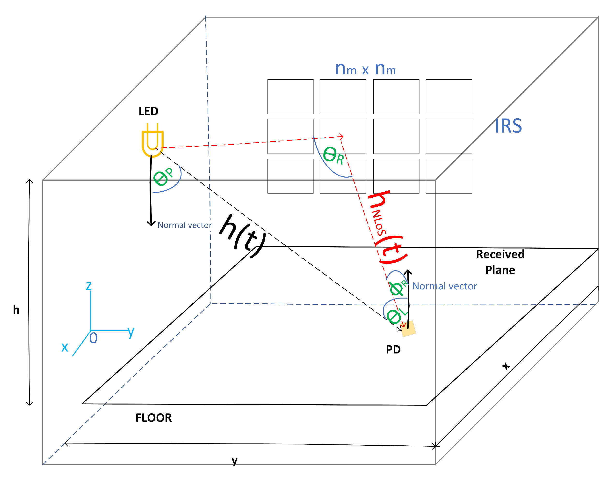
The scenario under consideration comprises a SISO downlink VLC system. We consider a noncoherent LED transmitter, oriented horizontally downwards and installed on the ceiling of the ideal indoor environment at a vertical distance from the horizontal plane containing the receiver, made up of a PD pointing vertically upwards as shown in Figure 2. Furthermore, we assume that the LED emulates a uniformly distributed planar radiation source distributed throughout its area, such as  A L = w L l L  with  w L  and  l L  being the sources distributed along the x-direction and the y-direction, respectively.
By adhering to a widely accepted convention, each individual point on the transmitter’s aperture exhibits a characteristic radiation pattern, conforming to the principles of Lambertian emission. This radiation pattern is characterized by a Lambertian order denoted as m. This concept is of particular significance in the domain of optical and communication systems and contributes to the uniform distribution of light and signals emitted across space.
The Lambertian radiation pattern captures the behavior of light emitted from a point source in a manner that adheres to Lambert’s cosine law. This law dictates that the radiant intensity of light varies with the cosine angle between the observer’s line of sight and the direction of emission. By extension, the Lambertian radiation pattern encapsulates the way light disperses more broadly when emitted from a surface. The parameter m defines the degree of Lambertian behavior, ranging from fully Lambertian ( m = 0 ) to less Lambertian-like as m increases. Therefore, the radiance of a general point on the LED is defined as [23]:
L ( θ L ) = P t ( m + 1 ) 2 π A L 2 cos m 1 ( θ L ) ,
where  m = 1 / log 2 [ cos ( ϕ 1 / 2 ) ] ϕ 1 / 2  is the half power beam-width,  θ L  is the radiance angle of the LED, and  P t  is the power transmitted by the LED.
On the other hand, we assume a vertically upward-oriented PD, which is based on hemispherical lenses that follow a Lambertian detection pattern with a respective FoV. The PD optical gain, denoted  g ( θ P ) , is given as follows [24]:
g ( θ P ) = η 2 s i n 2 ( θ P ) , if 0 θ P Θ 0 , if θ P Θ ,
where  η  is the reflective index of the PD,  θ P  is the incidence angle on the PD, and  Θ  is the FoV.
Once the LED emission and PD reception models have been defined, the LoS CIR of the VLC channel that governs the proposed scenario can be expressed as [25,26]
h ( t ) = A eff ( m + 1 ) 2 π d 2 cos m ( θ L ) cos ( θ P ) δ ( t d 0 c ) ,
where  A eff  is the effective signal collection area for the LoS path, c is the speed of the light in free space, and  δ ( t d 0 c )  represents the signal propagation delay.
In general, in real indoor scenarios, there are obstacles or obstructions that significantly affect the LoS component. In this context, a physical phenomenon that conditions these environments is shadowing. Due to its significant dependence on having a line of sight, the direct light component is very affected by the effect of this phenomenon. In general, people, immobile objects, and moving elements produce shadowing, so we consider it coherent to introduce an error probability coefficient in the mathematical expression of the LoS component, as follows [24,27,28]:
h ( t ) s h = h ( t ) P ,
where P is a weighting function that represents the probability that the LoS link will not be blocked [24,27,28]. This coefficient is a parameterized value between 0 and 1. That is, if there is a total blockage of the LoS link, its value will be 0. Otherwise, it will be 1 if there is no blockage. In this research, we have considered obtaining P based on a Gaussian Bimodal distribution, assuming that the greatest number of obstacles that can be produced on the scene will be people walking between the transmitter and receiver at certain times [29].

3. Intelligent Reconfigurable Surface Model

In the proposed VLC scenario, we consider that there are Non-LoS channel components, which are generated by reflections of light beams on reflective surfaces. In our case, to generate higher gains based on the resiliency to LoS blockages between the LED and the PD, we consider IRS as reflective surfaces. Specifically, we will assume smart metasurface reflectors. For this purpose, the IRS scenario consists of an array  n m × n m  of identical rectangular optical smart metasurface patches, with patch width  w m  and patch height  h m  located on a vertical surface perpendicular to the ground, as shown in Figure 2. It is important to mention that the position and shape of the IRS have the potential to influence signal propagation, coverage, and overall system efficiency. By carefully optimizing IRS placement within an indoor environment, signal quality can be maximized, leading to improved communication performance and user experience. This optimization could involve algorithms that take into account factors such as signal strength, interference, and line-of-sight conditions. Also, the choice of the shape of the IRS, specifically rectangular, deserves a discussion. Although it is true that a parabolic IRS could potentially improve reflection quality due to its focusing properties, practicality, and implementation complexities must also be considered. Rectangular IRS panels are more feasible to manufacture, install, and integrate into interior environments. The simplicity of its structure facilitates deployment and scalability, which are vital considerations in real-world scenarios. Furthermore, we assume that the phase discontinuity ( ϕ m ) of each element of the metasurface is independent of each of the patches. Therefore, it is assumed that the phase gradient will remain constant at each metasurface, such that [9]
δ ϕ m δ x = C k , l x x R k , l M S ,
δ ϕ m δ z = C k , l z z R k , l M S ,
where  R k , l M S k , l  represents the set of points located on an arbitrarily chosen meta-surface element in the k-th row and l-th column of the array of intelligent reflecting surfaces.
In order to minimize the transmittance for the IRS used in the VLC scenario, in addition to measuring and quantifying the gains and characteristics of the optical signals when interacting with these surfaces, we consider the following assumptions:
  • Reflective elements must have thicknesses much higher than the penetration depths of the metal used. To avoid polarization sensitivity, IRS is constructed without birefringent or dichroic materials.
  • The dimensions of the IRS must be much larger than the wavelength of visible light. Therefore, we adopt as in [9] a macroscopic model for each IRS, which allows us to consider them as equivalent anomalous reflective rectangular blocks. This approach makes it possible to harness and direct most of the incident light in a direction imposed by the generalized law of reflection. In addition, it implies the dependence of only two variables,  θ L  and  ϕ m  of the IRS.
  • The function of  ϕ m  for each IRS patch is adjusted so that the incident light beam from the LED strikes and reflects off the center of the reflector.
  • We have adjusted the duration of the symbol in the transmitter to avoid intersymbol interference.
  • IRS is perfectly smooth, so that nonspecular reflections can be neglected.
  • The IRS phase gradient is smooth for all directions found on the surface.
  • Data are transported on a white light beam to avoid reflection spectral dependencies.
Based on these considerations, we will derive the angles of incidence and radiance of the light beam on the IRS.

3.1. IRS Incidence and Radiance Angles

Prior to the derivation of the IRS incidence and radiance angles, it is important to mention that by means of the generalized reflection law (generalized Snell’s law) a relativistic relationship can be provided between the direction of the reflected and incident rays with respect to the normal to the surface and the IRS phase discontinuity. Therefore, the generalized reflection law can be written as [9]
cos ( θ R ) sin ( ϕ R ) = λ 2 π n R δ ϕ m δ r ,
sin ( θ R ) sin ( θ I ) = λ 2 π n R δ ϕ m δ i ,
where  θ R  is the angle between the reflected light beam and its projection on the plane orthogonal to the plane of incidence and the IRS patch,  ϕ R  is the angle between the vector normal to the IRS and the projection of the reflected light beam in the plane orthogonal to both the plane of incidence and the IRS,  λ  denotes the wavelength,  n R  represents the refractive index of the incidence medium,  r  is the counterclockwise rotated version of the x axis about the y axis,  θ I  is the incidence angle on the IRS, which is considered as the angle between the incident light beam and the vector normal to the IRS, and  i  represents the counterclockwise rotated version of the z axis about the y axis.
The generalized relativistic expressions of Snell’s law can be developed in terms of the Cartesian coordinates of the scenario and use basic trigonometric identities. Therefore, we can obtain a closed-form representation of  θ R  and  ϕ R  as follows:
sin ( θ ) sin ( ϕ ) sin ( θ R ) sin ( ϕ R ) = λ 2 π n R δ ϕ m δ x ,
sin ( θ ) sin ( ϕ ) sin ( θ R ) cos ( ϕ R ) = λ 2 π n R δ ϕ m δ z ,
or, finding the expressions in terms of  θ R  and  ϕ R ,
θ R = sin 1 sin ( θ ) sin ( ϕ ) λ 2 π n R δ ϕ m δ x 2 + sin ( θ ) cos ( ϕ ) λ 2 π n R δ ϕ m δ z 2 1 2 ,
ϕ R = tan 1 sin ( θ ) sin ( ϕ ) λ 2 π n R δ ϕ m δ x sin ( θ ) cos ( ϕ ) λ 2 π n R δ ϕ m δ z + π I sin ( θ ) cos ( ϕ ) λ 2 π n R δ ϕ m δ z ,
where  θ  denotes the angle between the normal to the IRS and the reflected ray,  ϕ  represents the angle between the projection of the reflected ray onto the IRS and a ray parallel to the z-axis lying in that plane, and  I ( s )  is an indicator function with a binary behavior, depending on whether the condition s is satisfied  I ( s ) = 1  or not  I ( s ) = 0 .

3.2. Reflective Channel Component

Due to the diffuse optical component, the sum of all reflections arriving at the PD generates the non-LoS component, namely  h N L o S ( t )  [25]. In this work, we consider only the first bounce of the reflections of the IRS model for practical and analytical purposes, based on the paradigm that the reflections caused by a large number of bounces are negligible, so the first bounce becomes the most important component that affects the received power and its temporal dispersion [25]. Therefore, the CIR of the Non-LoS component can be expressed as follows [25]:
h N L o S ( t ) = ( m + 1 ) 2 π k = 1 n m l = 1 n m ϕ m d k , l 2 cos m ( θ L ) c o s ( θ I ) c o s ( ϕ R k , l ) cos ( θ R k , l ) δ t d k , l c ,
where the Euclidean distances between the LED and the effective area of the IRS path, and between the effective area of the IRS path and the PD are given by  d k , l .
Finally, the total CIR for the VLC channel  ( h t ( t ) )  is the sum of the LoS (Equation (4)) and Non-LoS (Equation (13)) components, namely,
h t ( t ) = h ( t ) s h + h N L o S ( t ) .

4. Simulation Results and Discussion

In this section, we evaluate the performance of the VLC system implemented with an IRS applied to a typical indoor environment. To achieve this goal, we studied typical performance metrics of the communications systems, such as CIR and BER. The results are obtained through computational simulations through Matlab software, the ray-tracing methodology by varying the number of Non-LoS links (reflections) that reach the receiver, and the Monte Carlo simulation scheme. The parameters used for the simulations are summarized in Table 1.

4.1. Bit Error Rate of the System

Based on the IEEE 802.15.7 standard and the type of optical signal to comply with the IM/DD paradigm [30], in our work, the ON-OFF keying modulation (OOK) was used as shown in Table 1. Furthermore, the receiver location is varied and goes through the entire scenario to obtain the results. Finally, the shot and thermal noises widely used in typical VLC environments are considered [25,26].
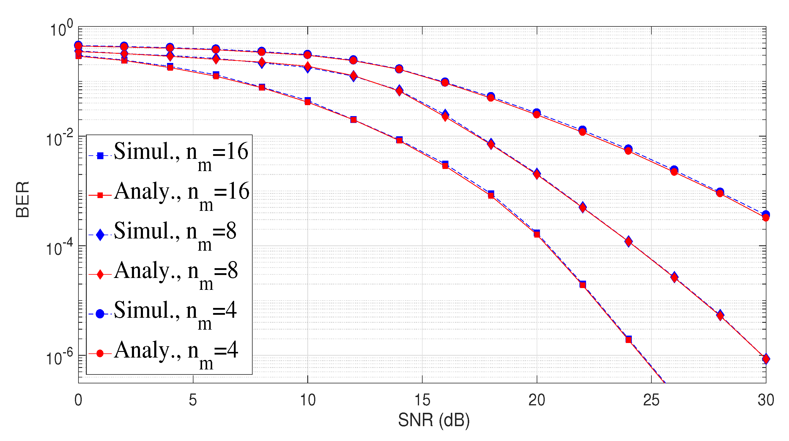
The BER was estimated using Monte Carlo simulations with the direct error counting method, that is, 21 runs of  10 5  bits were performed to have a confidence interval of 95% [25]. In this context, we measure the BER of the VLC system using typical standard equations and parameters for OOK modulation [25]. The simulated BER curves are shown in Figure 3, which measure the performance of the system based on the channel model proposed in Equation (14), the proposed VLC scenario, and the variation of  n m  for different Signal-to-Noise-Ratio (SNR) values. For validation purposes, we adjust the value of P based on a Gaussian Bimodal distribution [29] and explicitly compare the curves obtained through simulations with the analytical BER evaluation, showing excellent agreement.
From Figure 3, we can see that the best performance in terms of BER is obtained for  n m = 16 . This result shows that the greater the number of rectangular optical smart metasurface patches that make up the IRS matrix, the greater the probability that they reach the receiver properly. This is due to the angular variation capacity so that when there is blocking of the LoS component, the Non-LoS component is the one that predominates, thus maintaining the power quality of the received signal. Therefore, this effect would improve the performance of the implemented VLC system. For example, for a BER of  9 × 10 4 , the SNR obtained is approximately 20 dB. On the other hand, for the same SNR value, we obtain an approximate BER of  9 × 10 3  for  n m = 8  and  9 × 10 2  for  n m = 4 . These results demonstrate the positive effect of having a greater number of rectangular optical smart metasurface patches in the IRS. In order to obtain a complete approach to the variability of system performance according to changes in the PD position, we consider providing information on the BER standard deviation in our results. For  n m  = 4 a standard deviation of 0.00154 was obtained, while for values of  n m  = 8 and  n m  = 16 values of 0.00143 and 0.00123 were obtained, respectively. This statistic allows us to intuit that the fluctuation of the BER in terms of the positions is appropriate for this type of system.
Finally, we have observed that the value of  n m  has a significant impact on the IRS about its performance in the VLC system. With higher values of  n m , IRS could achieve higher precision, for example, in phase modulation, which in turn allows for an improvement in the quality of the reflected signal and a reduction in BER. However, it is also important to note that there are practical limits associated with increasing  n m . Among these limits are the complexity of the implementation, the amount of resources required, and the ability to control the phases in real-time.

4.2. Channel Impulse Response of the VLC System

We consider a number of coherent optical paths (rays) to obtain relevant results without consuming excessive computational resources. Furthermore, we calculate the received power and the Euclidean distance between the LED and the PD to obtain the length of each of the optical rays and assume the value of P based on the Gaussian Bimodal Distribution [29]. This methodology involves the variation of the position of the PD throughout the scenario and its effect on the system performance by changing the distance between the PD with the LED and the PD with the IRS. Finally, these variables are processed by theoretical calculations to obtain the BER considering the average of all PD positions and the total CIR in the scenario and for various values of P. For simulation purposes, we assume that the transmitted power is 20 watts.
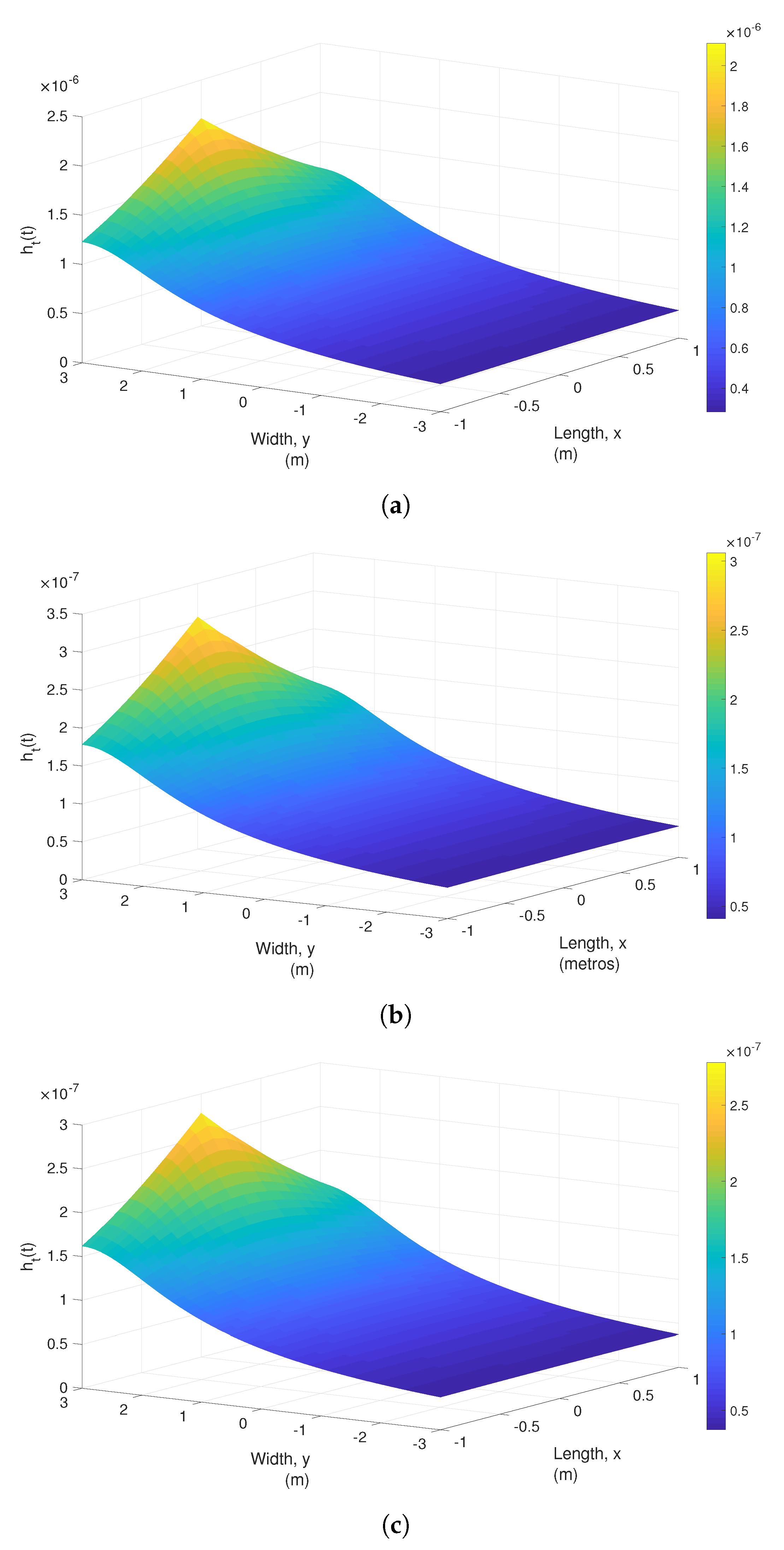
Figure 4 shows the distribution of CIR throughout the simulated environment for some values of  n m . We can see that, as with the BER, for a value of  n m = 16  (Figure 4a), the best CIR results are obtained in terms of their amplitude value. Indeed, we can see that the maximum and minimum CIR values obtained in the indoor scenario are 2.2 ×  10 6  and 0.25 ×  10 6 , respectively. These values are the best obtained if we compare them with the values obtained for  n m = 8  (Figure 4b) and  n m = 4  (Figure 4c). Therefore, these findings reinforce our criteria to improve system performance by increasing the values of  n m . We can also notice in all scenarios that the magnitudes of the CIR are not uniform; this is due to the different distances between the LED and the PD and their effect on reception, as well as the distances between the LED, the IRS, and the PD. Another important factor that produces the nonuniformity of the CIR in the scenario is the probability of blocking the LoS signal. At the signal blocking points, we can observe a lower CIR, in which the Non-LoS component produced by the reflections in the IRS prevails. This gives us a positive effect on the performance of the system, since there is never a total loss of optical signal around the indoor scenario.
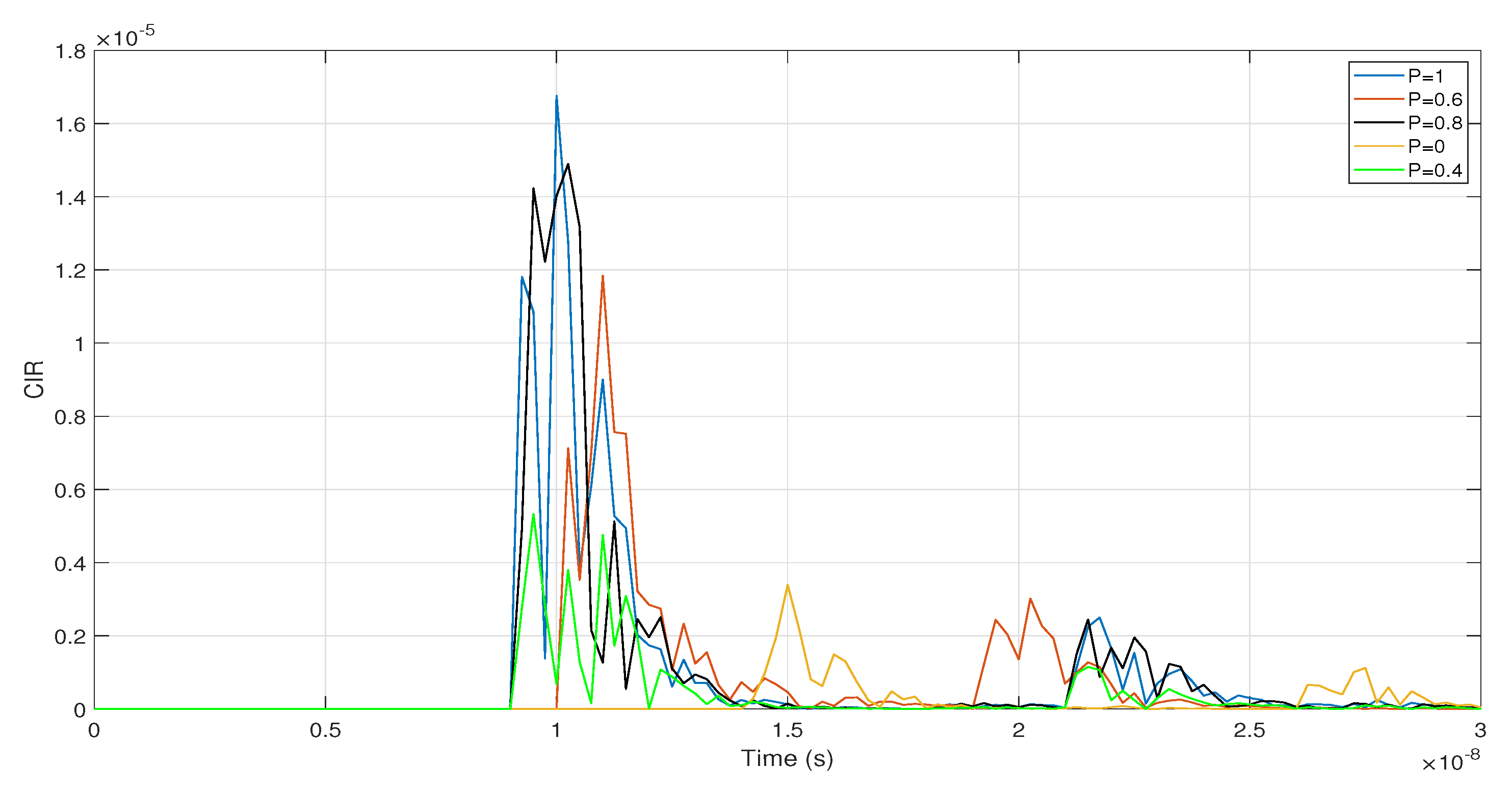
Finally, Figure 5 shows the CIR curves obtained by varying the P values for a PD located in the center of the scenario. As we can see, when the values of P decrease (i.e., the probability of nonblocking of the optical link decreases), the maximum magnitude obtained by the initial LoS component also decreases. This effect is coherent since the partial or total blocking of this component is a critical factor in the received power. However, we realize that, despite the fact that there is blocking of the optical signal, the reflection components produced by the IRS are maintained and differ very little in magnitude for the different values of P. In fact, for a value of  P = 0  (full blocking), the components produced by the IRS remain at a good level. This allows us to analyze and identify the constructive effect of these elements in keeping a VLC system stable in performance.

5. Conclusions

In this article, IRS use was analyzed and evaluated in the indoor VLC system to identify possible improvements in the performance of the VLC environment. Furthermore, analytical expressions were presented to include the effect of IRS on the light beam, the probability that the LoS link will not be blocked, and proposed more realistic theoretical optical components. The performance of the VLC system was evaluated and compared in terms of CIR and BER by varying the number of rectangular optical smart metasurface patches in the IRS. Specifically for  n m = 16 , we have maximum and minimum CIR values of 2.2 ×  10 6  and 0.25 ×  10 6 , respectively, which are the best values obtained compared to the scenarios for  n m = 8  and  n m = 4 . The results obtained through computer simulations of the VLC scenario show that having a greater number of rectangular optical smart metasurface patches in the IRS, also increases the probability that light beams contributing to the Non-LoS component will reach the receiver optimally. Therefore, the system improves its performance in terms of the metrics evaluated. This would imply that the presented solution is quite promising to implement an efficient VLC system as an enabling technology for 6G. Finally, as future work, the position of the IRS and the  ϕ m  parameter will be optimized in scenarios based on experimental test beds to generate more efficient practical applications in indoor environments. In addition, more accurate channel models for IRS systems with direct and non-direct optical links will be studied and developed.

Author Contributions

Conceptualization, M.R.C. and P.P.J.; methodology, M.R.C. and P.P.J.; software, M.R.C. and P.P.J.; validation, J.G.-M., W.V.-C. and C.A.-M.; formal analysis, M.R.C. and P.P.J.; investigation, M.R.C. and P.P.J.; resources, J.G.-M., W.V.-C. and C.A.-M.; data curation, M.R.C. and P.P.J.; writing—original draft preparation, M.R.C. and P.P.J.; writing—review and editing, J.G.-M., W.V.-C. and C.A.-M.; supervision, J.G.-M., W.V.-C. and C.A.-M.; project administration, J.G.-M., W.V.-C. and C.A.-M.; funding acquisition, J.G.-M., W.V.-C. and C.A.-M. All authors have read and agreed to the published version of the manuscript.

Funding

This research was funded by ANID FONDECYT Regular No. 1211132, and Facultad de Ingeniería, Pontificia Universidad Católica del Ecuador.

Institutional Review Board Statement

Not applicable.

Informed Consent Statement

Not applicable.

Data Availability Statement

The data presented in this study are available on request from the corresponding author.

Acknowledgments

This work was supported by SENESCYT “Convocatoria abierta 2014-primera fase, Acta CIBAE-023-2014”; Escuela de Ingeniería en Ciberseguridad, FICA, Universidad de Las Américas, and Escuela de Informática y Telecomunicaciones, Universidad Diego Portales. The authors thank F. Javier López-Martnez for his help and insightful discussion of this work.

Conflicts of Interest

The authors declare no conflict of interest.

Abbreviations

The following abbreviations are used in this manuscript:
BERBit Error Rate
CIRChannel Impulse Response
CSIChannel State Information
DDDirect Detection
FoVField-of-View
FSOFree Space Optical
IMIntensity Modulation
IRSIntelligent Reconfigurable Surfaces
LEDLight-Emitting Diode
LoSLine-of-Sight
Non-LoSNon-Line of Sight
OOKON-OFF Keying
PDPhoto-Diode
RFRadio Frequency
SINRSignal to Interference plus-Noise-Ratio
SLMSpatial Light Modulator
SNRSignal-to-Noise-Ratio
SISOSingle Input Single Output
VLCVisible Light Communication
V2VVehicle to Vehicle

References

  1. De Alwis, C.; Kalla, A.; Pham, Q.V.; Kumar, P.; Dev, K.; Hwang, W.J.; Liyanage, M. Survey on 6G frontiers: Trends, applications, requirements, technologies and future research. IEEE Open J. Commun. Soc. 2021, 2, 836–886. [Google Scholar] [CrossRef]
  2. Porambage, P.; Gür, G.; Osorio, D.P.M.; Liyanage, M.; Gurtov, A.; Ylianttila, M. The roadmap to 6G security and privacy. IEEE Open J. Commun. Soc. 2021, 2, 1094–1122. [Google Scholar] [CrossRef]
  3. Aboagye, S.; Ndjiongue, A.R.; Ngatched, T.M.; Dobre, O.A.; Poor, H.V. RIS-assisted visible light communication systems: A tutorial. IEEE Commun. Surv. Tutor. 2022, 25, 251–288. [Google Scholar] [CrossRef]
  4. Sun, S.; Wang, T.; Yang, F.; Song, J.; Han, Z. Intelligent reflecting surface-aided visible light communications: Potentials and challenges. IEEE Veh. Technol. Mag. 2021, 17, 47–56. [Google Scholar] [CrossRef]
  5. Zhu, X.; Wang, C.X.; Huang, J.; Chen, M.; Haas, H. A Novel 3D Non-Stationary Channel Model for 6G Indoor Visible Light Communication Systems. IEEE Trans. Wirel. Commun. 2022, 21, 8292–8307. [Google Scholar] [CrossRef]
  6. Ndjiongue, A.R.; Ngatched, T.M.; Dobre, O.A.; Haas, H. Toward the use of re-configurable intelligent surfaces in VLC systems: Beam steering. IEEE Wirel. Commun. 2021, 28, 156–162. [Google Scholar] [CrossRef]
  7. Román Cañizares, M.; Palacios Játiva, P.; Azurdia-Meza, C.A.; Montejo-Sánchez, S.; Céspedes, S. Impact of diversity combining schemes in a multi-cell VLC system with angle diversity receivers. Photonic Netw. Commun. 2022, 43, 13–22. [Google Scholar] [CrossRef]
  8. Abumarshoud, H.; Mohjazi, L.; Dobre, O.A.; Di Renzo, M.; Imran, M.A.; Haas, H. LiFi through reconfigurable intelligent surfaces: A new frontier for 6G? arXiv 2021, arXiv:2104.02390. [Google Scholar] [CrossRef]
  9. Abdelhady, A.M.; Salem, A.K.S.; Amin, O.; Shihada, B.; Alouini, M.S. Visible light communications via intelligent reflecting surfaces: Metasurfaces vs mirror arrays. IEEE Open J. Commun. Soc. 2020, 2, 1–20. [Google Scholar] [CrossRef]
  10. Shafique, T.; Tabassum, H.; Hossain, E. Stochastic geometry analysis of IRS-assisted downlink cellular networks. IEEE Trans. Commun. 2022, 70, 1442–1456. [Google Scholar] [CrossRef]
  11. Zhou, X.; Yan, S.; Wu, Q.; Shu, F.; Ng, D.W.K. Intelligent reflecting surface (IRS)-aided covert wireless communications with delay constraint. IEEE Trans. Wirel. Commun. 2021, 21, 532–547. [Google Scholar] [CrossRef]
  12. Najafi, M.; Schmauss, B.; Schober, R. Intelligent reflecting surfaces for free space optical communication systems. IEEE Trans. Commun. 2021, 69, 6134–6151. [Google Scholar] [CrossRef]
  13. Yuan, X.; Zhang, Y.J.A.; Shi, Y.; Yan, W.; Liu, H. Reconfigurable-intelligent-surface empowered wireless communications: Challenges and opportunities. IEEE Wirel. Commun. 2021, 28, 136–143. [Google Scholar] [CrossRef]
  14. Wu, Q.; Zhang, S.; Zheng, B.; You, C.; Zhang, R. Intelligent reflecting surface-aided wireless communications: A tutorial. IEEE Trans. Commun. 2021, 69, 3313–3351. [Google Scholar] [CrossRef]
  15. Arfaoui, M.A.; Ghrayeb, A.; Assi, C. Integration of IRS in Indoor VLC Systems: Challenges, Potential and Promising Solutions. arXiv 2021, arXiv:2101.05927. [Google Scholar]
  16. Nemati, A.; Wang, Q.; Hong, M.; Teng, J. Tunable and reconfigurable metasurfaces and metadevices. Opto-Electron. Adv. 2018, 1, 180009. [Google Scholar] [CrossRef]
  17. Sun, S.; Yang, F.; Song, J.; Zhang, R. Intelligent reflecting surface for MIMO VLC: Joint design of surface configuration and transceiver signal processing. IEEE Trans. Wirel. Commun. 2023, 22, 5785–5799. [Google Scholar] [CrossRef]
  18. Valagiannopoulos, C.; Tsiftsis, T.A.; Kovanis, V. Metasurface-enabled interference mitigation in visible light communication architectures. J. Opt. 2019, 21, 115702. [Google Scholar] [CrossRef]
  19. Mohsan, S.A.H.; Khan, M.A.; Amjad, H. Hybrid FSO/RF networks: A review of practical constraints, applications and challenges. Opt. Switch. Netw. 2023, 47, 100697. [Google Scholar] [CrossRef]
  20. Stefanovic, C.; Morales-Céspedes, M.; Armada, A.G. Performance analysis of RIS-assisted FSO communications over Fisher–Snedecor F turbulence channels. Appl. Sci. 2021, 11, 10149. [Google Scholar] [CrossRef]
  21. Gomez, A.; Shi, K.; Quintana, C.; Sato, M.; Faulkner, G.; Thomsen, B.C.; O’Brien, D. Beyond 100-Gb/s Indoor Wide Field-of-View Optical Wireless Communications. IEEE Photonics Technol. Lett. 2015, 27, 367–370. [Google Scholar] [CrossRef]
  22. Jian, Y.H.; Wang, C.C.; Chow, C.W.; Gunawan, W.H.; Wei, T.C.; Liu, Y.; Yeh, C.H. Optical Beam Steerable Orthogonal Frequency Division Multiplexing (OFDM) Non-Orthogonal Multiple Access (NOMA) Visible Light Communication Using Spatial-Light Modulator Based Reconfigurable Intelligent Surface. IEEE Photonics J. 2023, 15, 1–8. [Google Scholar] [CrossRef]
  23. Palacios Játiva, P.; Azurdia-Meza, C.A.; Sánchez, I.; Zabala-Blanco, D.; Dehghan Firoozabadi, A.; Soto, I.; Seguel, F. An Enhanced VLC Channel Model for Underground Mining Environments Considering a 3D Dust Particle Distribution Model. Sensors 2022, 22, 2483. [Google Scholar] [CrossRef] [PubMed]
  24. Játiva, P.P.; Azurdia-Meza, C.A.; Sánchez, I.; Seguel, F.; Zabala-Blanco, D.; Firoozabadi, A.D.; Gutiérrez, C.A.; Soto, I. A VLC Channel Model for Underground Mining Environments with Scattering and Shadowing. IEEE Access 2020, 8, 185445–185464. [Google Scholar] [CrossRef]
  25. Ghassemlooy, Z.; Popoola, W.; Rajbhandari, S. Optical Wireless Communications: System and Channel Modelling with Matlab®; CRC Press: Boca Raton, FL, USA, 2017. [Google Scholar]
  26. Palacios Játiva, P.; Román Cañizares, M.; Azurdia-Meza, C.A.; Zabala-Blanco, D.; Dehghan Firoozabadi, A.; Seguel, F.; Montejo-Sánchez, S.; Soto, I. Interference mitigation for visible light communications in underground mines using angle diversity receivers. Sensors 2020, 20, 367. [Google Scholar] [CrossRef]
  27. Becerra, R.; Azurdia-Meza, C.A.; Palacios Játiva, P.; Soto, I.; Sandoval, J.; Ijaz, M.; Carrera, D.F. A Wavelength-Dependent Visible Light Communication Channel Model for Underground Environments and Its Performance Using a Color-Shift Keying Modulation Scheme. Electronics 2023, 12, 577. [Google Scholar] [CrossRef]
  28. Xiang, Y.; Zhang, M.; Kavehrad, M.; Chowdhury, M.S.; Liu, M.; Wu, J.; Tang, X. Human shadowing effect on indoor visible light communications channel characteristics. Opt. Eng. 2014, 53, 86113. [Google Scholar] [CrossRef]
  29. Játiva, P.P.; Azurdia-Meza, C.A.; Cañizares, M.R.; Sánchez, I.; Seguel, F.; Zabala-Blanco, D.; Carrera, D.F. Performance analysis of IEEE 802.15. 7-based visible light communication systems in underground mine environments. Photonic Netw. Commun. 2022, 43, 23–33. [Google Scholar] [CrossRef]
  30. Jativa, P.P.; Azurdia-Meza, C.A.; Zabala-Blanco, D.; Gutiérrez, C.A.; Sanchez, I.; Castillo-Soria, F.R.; Seguel, F. Bit Error Probability of VLC Systems in Underground Mining Channels with Imperfect CSI. AEU-Int. J. Electron. Commun. 2022, 145, 154101. [Google Scholar] [CrossRef]
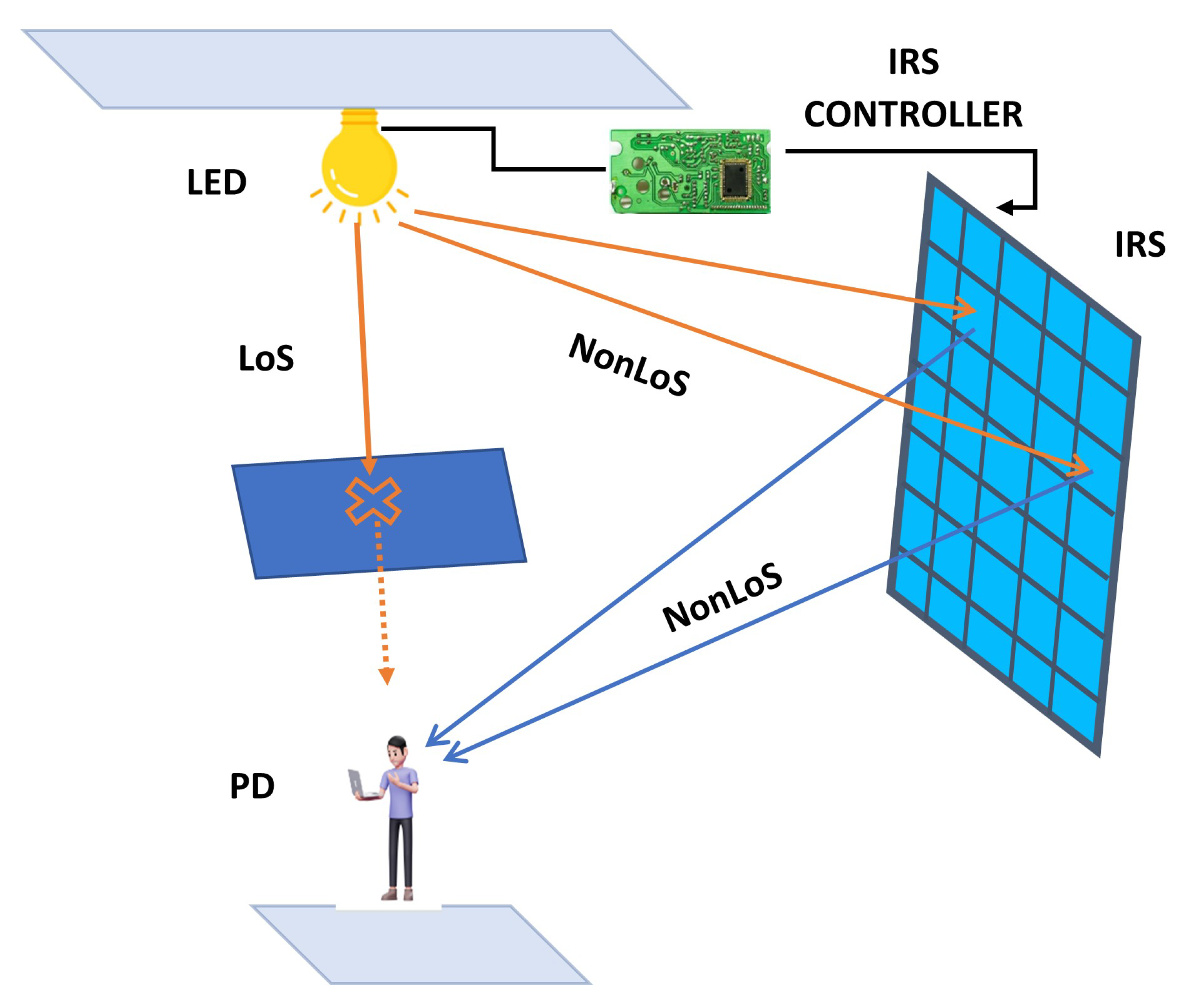
Figure 1. Basic schematic of an IRS-aided VLC System.
Photonics 10 01117 g001
Figure 2. VLC scenario with optical propagation geometric scheme and IRS positioning.
Photonics 10 01117 g002
Figure 3. BER vs. SNR for different values of  n m .
Photonics 10 01117 g003
Figure 4. CIR distribution on the VLC scenario for some values of  n m . (a n m = 16 . (b n m = 8 . (c n m = 4 .
Photonics 10 01117 g004
Figure 5. CIR curves for different values of P.
Photonics 10 01117 g005
Table 1. Default simulations parameters.
System Model ParametersValuesReferences
Average output optical power20 W[9,24,26]
Band-pass filter of transmission1[24,26]
Dimensions (w × l × h)(3 × 6 × 3) m
Gain of the optical filter1[24,26]
LED position  (x, y, z)(0, 3, 2) m
LED semi-angle at half power   60 ° [24,26]
ModulationOOK[24,26]
Modulation bandwidth50 MHz[24,26]
Modulation index0.3[24,26]
Number of PDs1
Open-loop voltage gain10[24,26]
Optical filter bandwidth340 nm to 694.3 nm[30]
Optical filter center wavelength340 ± 2 nm[30]
Optical filter full width half max10 ± 2 nm[30]
Phase discontinuity ( ϕ m )[− 180 ° , 180 ° ]
PD physical area1 cm 2  [24,26]
PD FoV60 ° [24,26]
Refractive index1.5[24,26]
Reflection coefficient0.8[24,26]
Responsivity0.53 A/W[24,26]
Disclaimer/Publisher’s Note: The statements, opinions and data contained in all publications are solely those of the individual author(s) and contributor(s) and not of MDPI and/or the editor(s). MDPI and/or the editor(s) disclaim responsibility for any injury to people or property resulting from any ideas, methods, instructions or products referred to in the content.