Article

Stable Acoustic Pulling in Two-Dimensional Phononic Crystal Waveguides Based on Mode Manipulation

1
Institute of Advanced Photonics, School of Physics, Harbin Institute of Technology, Harbin 150001, China
2
School of Physics, Dalian University of Technology, Dalian 116024, China
3
Department of Physics, School of Science, Northeast Forestry University, Harbin 150040, China
4
Collaborative Innovation Center of Extreme Optics, Shanxi University, Taiyuan 030006, China
*
Authors to whom correspondence should be addressed.
Photonics 2023, 10(12), 1325; https://doi.org/10.3390/photonics10121325
Submission received: 31 October 2023 / Revised: 24 November 2023 / Accepted: 28 November 2023 / Published: 29 November 2023

Abstract

:
Acoustic manipulation is a set of versatile platforms with excellent manipulation capabilities. In recent years, researchers have increasingly achieved specific manipulations beyond the translation and capture of particles. Here, we focus on the acoustic field momentum mechanism that generates an acoustic radiation force (ARF). A phononic crystal (PC) waveguide is established to amplify the forward momentum of the acoustic beam through the mode conversion of the acoustic field. Based on the conservation of momentum, the object gains reverse momentum. Thus, acoustic pulling can be achieved through the mode conversion of the acoustic field. Furthermore, we analyze the ARFs of two identical objects. It turns out that they can be manipulated separately by opposing forces. Our study provides a new way to achieve stable long-range acoustic pulling, and will explore, beneficially, the interaction between acoustic waves and matter.

1. Introduction

Noncontact manipulation plays a significant role in a large number of modern scientific and technological fields, such as biophysics [1], life science [2,3], and nanotechnology [4]. Since Ashkin’s pioneering work on optical tweezers was performed in the early 1970s [5], optical tweezers have become a favorite way to manipulate particles. Although optical tweezer technology has relatively high resolution and precision [6,7,8,9], the thermal effect [10,11,12] generated by high-power energy causes damage to controlled particles to easily occur. Moreover, it has certain requirements for the electromagnetic properties [13] of the controlled objects, and there are limitations in the control of relatively large objects [14]. In contrast, acoustic tweezers act as an emerging contactless manipulation platform, which has the advantages of large forces [15], great biocompatibility [16,17], and label-free manipulation [18,19]. Additionally, acoustic tweezers have no special requirements for materials and do not damage cell activity [20,21]. Due to the incomparable advantages in biological research [22], acoustic tweezers have great research value in applications such as precisely targeted drug delivery [23,24,25], the manipulation of living biological cells [26,27], and remote sample capture and separation [28,29].
The earliest theory of acoustic tweezers was proposed by A. Kundt and O. Lehmann [30]. It was found that the powder in the glass tube was redistributed under the action of an ultrasonic standing wave field, and stably suspended at the standing wave node. In the past few decades, the interaction between acoustic waves and objects has been mainly about pushing and trapping [31,32]. Hence, how can we overcome this pushing and achieve pulling using acoustic waves toward the source? This is a huge area of interest and challenge for researchers. Although C.E.M. Démoré et al. [33] proposed the construction of a tractor acoustic beam using a transducer to achieve pulling on objects, it had extremely strict requirements for the material parameters of objects. At present, the generation of a negative acoustic radiation force (ARF) is mainly achieved using acoustic Bessel beams [34,35,36] or the interference of multiple beams [37,38]. Due to the limitations of the frequency and bandwidth of the transducer and the spatial mode of the beam, acoustic pulling not only has strict requirements for acoustic waves and particles but is also limited by short distances.
After the introduction of phononic crystals (PCs) [39], different acoustic fields can be generated with the band structure and modal theory, which enriches particle manipulation methods. Furthermore, PCs have unique properties that have received extensive attention, including the demonstration of a subwavelength resolution [40], self-collimation [41], and negative reflection [42]. When periodicity is broken by utilizing defects or cavities, it can generate local states and open the propagating modes, such as the linear guidance mechanism [43]. Here, we propose a novel method to achieve long-range acoustic pulling based on mode manipulation in the PC waveguide. Our method does not rely on the scattering force between the acoustic waves and the manipulated object but amplifies the forward momentum of the acoustic waves based on mode manipulation. According to theoretical analysis, when acoustic waves propagate in an m-th order mode with the propagation constant, km, each phonon carries a momentum of ℏkm and km always decreases as m increases. When the mode of acoustic wave propagation is disturbed by an object, mode conversion between different modes will occur [44], and the momentum of the acoustic waves will change. Based on the conservation of momentum, the decrease in the mode index during conversion can result in the emergence of an acoustic pulling force. Here, the acoustic forces are calculated accurately by utilizing the closed-surface integral of the time-averaged radiation stress tensor and analyzing the acoustic field of mode conversion. Our results show that the longitudinal acoustic force (i.e., that propagating along the wave) acting on the particle is negative once the relatively smaller mode index is generated via mode conversion. In addition, two objects can be subjected to an acoustic pulling force and pushing force, which can result in differing paths to achieve separation.

2. The Model

Consider a two-dimensional (2D) PC structure with a square lattice formed using a copper column in the air, as shown in Figure 1. In this study, a linear defect waveguide is achieved by breaking the periodic symmetry of PCs, which opens up the multiple propagating modes [45]. First, the band structure of PCs without a waveguide is illustrated in Figure 1a. It is observed that the first transmission band of the PC extends to 11.3 kHz from the origin, as signified by the complete bandgap that occurs between 11.3 kHz and 20 kHz. The lattice constant, a, is 12 mm. The parameters of the copper column are mass density, ρ = 8600 kg·m−3; longitudinal wave speed, cl = 4400 m·s−1; and radius, r = 5.52 mm. The whole system is in the air (ρair = 1.29 kg·m−3; cair = 343 m·s−1). We use the eigen evaluations of COMSOL 6.0 to simulate the band structure of the PC waveguide, as shown in Figure 1b. The boundaries of the unit cell of the PC waveguide are set as plane wave radiation boundaries along the edge direction, with the perpendicular direction set as Floquet periodic boundaries. It can be observed that the PC waveguide has a variety of propagation modes, including three modes (C1, C2 and C3) when the frequency is 13.6 kHz (the black dotted line). It is worth noting that only two modes of propagation are supported in the frequency range of 14.5 kHz to 15 kHz. Moreover, the selected frequency is in the band gap of the PCs. To better illustrate the mode conversion process, as well as the generation of acoustic pulling being more feasible, we select a dual-mode frequency for discussion, and momentum conversion occurs between these two modes only. Here, we select a frequency of 14.6 kHz as an example (blue solid line in Figure 1b), which corresponds to a dual mode, as marked by A (the fourth-order mode) and B (the third-order mode), and the wave vectors of them are kxA = 0.45 (π/a) and kxB = 0.79 (π/a), respectively. The acoustic pressure field patterns of the two modes are shown in Figure 1c,d. Point A is the fourth-order mode (in Figure 1c) and has three nodes on the symmetry axis of the waveguide. Point B is the third-order mode (in Figure 1d) and has two nodes. When the acoustic field is converted from the fourth-order mode into the third-order mode, the forward momentum increases, so an acoustic pulling force may be generated on the scatter.
A quadrupole point sound source [46] is used to excite the waveguide from the left side and adopt a perfectly matched layer (PML) to eliminate the influence of reflected acoustic waves. The computational domain is divided by quadratic Lagrange triangular mesh elements. The quadrupole point sound source can be regarded as a dipole with two opposite phases and belongs to a stress sound source. Its directivity diagram is “four-leaf rose linearly”, and the radiated power is proportional to the eighth square of the airflow velocity. The use of a quadrupole point sound source can ensure that the acoustic waves propagate in one mode without clutter.
The ARF of the particle can be calculated by integrating the time-averaged Brillouin radiation stress tensor T on the closed surface surrounding the particle [47,48] as follows:
F = S T d S .
where the differential area, dS, indicates the outer normal of a surface enclosing the particle and T is expressed as follows:
T = ρ 2 2 ρ 0 c 0 2 ρ 0 v 2 2 I + ρ 0 vv
where I stands for a unit tensor, ρ0 and c0 are the density and the acoustic speed of the fluid, and v and p denote the velocity and pressure field.
The dimensionless radiation force can be obtained as follows:
Y x , y = F x , y / I 0
where I0 is the density of acoustic energy when an acoustic wave passes through the same location in the absence of an object, and Yx and Yy are the dimensionless radiation force functions in the x and y directions, respectively.

3. Results and Discussion

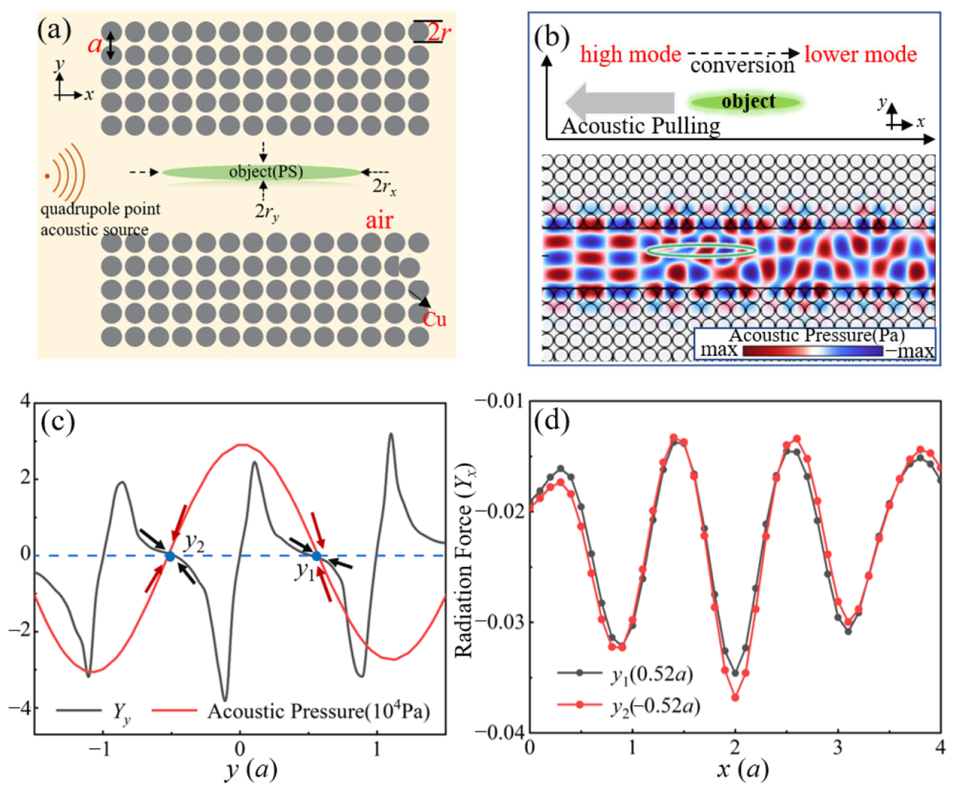
For a polystyrene (PS) elliptic object, we calculate the ARF acting on the particle and analyze the acoustic pressure field, as shown in Figure 2. Figure 2a shows the detailed settings of the system, and the object with the semi-major axis, rx = 3.6a and the semi-minor axis, ry = 0.34a. Figure 2b shows the acoustic pressure field after being scattered by the object. It can be seen that the fourth-order mode is converted into the mixed mode dominated by the third-order mode. Then, the lateral ARF (Yy) acting on the object is illustrated in the waveguide, as shown in Figure 2c. When there are no objects in the system, the acoustic pressure value of x = 2a is depicted by the red solid line. The black solid line represents Yy when the object’s center is located x = 2a. It is found that the object is captured at the pressure node positions y1 = 0.52a and y2 = −0.52a. This is because the acoustic waves create a trap at the pressure node (anti-node), and the object is steadily trapped at the pressure node (positive acoustic contrast particles) or anti-node (negative acoustic contrast particles) [49]. Specifically, the object is made of polystyrene with a positive acoustic contrast factor, so it is stably trapped at the pressure node. In addition, the longitudinal ARF (Yx) acting on the object is shown in Figure 2d. When the object is located at y1 = 0.52a and y2 = −0.52a, Yx is negative (opposite to the propagation direction of acoustic waves). The relatively smaller mode is generated via mode conversion, as shown in Figure 2b, so the longitudinal acoustic force acting on the particle is a continuous and long-term acoustic pulling force. The simulation results show that the scheme of mode conversion to generate acoustic pulling is feasible.
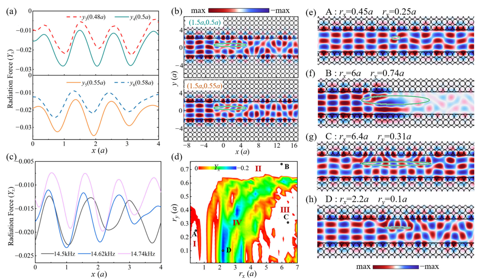
To further achieve the steady pulling of the object, the ARF acting on the object is considered at the different positions and frequencies. Firstly, we discuss the case where the object deviates from the stability point of 0.52a in the y direction, which is located below or above it. In Figure 3a, the ARF (Yx) is still a negative force and is greater when the object approaches the stable point, 0.52a. In addition, we discuss the simulation of the acoustic pressure fields with the object located at (1.5a, 0.5a) and (1.5a, 0.55a), as shown in Figure 4b. The mode of the acoustic wave can still be converted. Secondly, Figure 1b previously showed that the waveguide can realize dual-mode propagation in the frequency range of 14.5 kHz–15 kHz. It is found that with the ARF exerted on the object, Yx is still a negative force at different frequencies in that range, as shown in Figure 3c. Our pulling force not only enables stable pulling but also has multiple adjustable frequencies that are not limited to a single frequency.
In actual situations, the size of the object may be different and affect the acoustic force. The semi-major axis is rx and the semi-minor axis is ry; the results are shown in Figure 3d. It can be seen that in the rx from 2a to 4a, and in the ry from 0.1a to 0.65a, the acoustic force is negative in some regions, while it is positive (the white areas) in other regions. The whole region is divided into four regions. Region I indicates that the object is smaller, and the ARF is positive. When the wavelength of the acoustic wave is much larger than that of the object, the diffraction of the acoustic wave, such as the acoustic pressure field of the object (point A, rx = 0.45a, ry = 0.25a), will occur, as shown in Figure 3e. Region II represents the object with a large ry, and the ARF is positive. When the semi-minor axis, ry, is larger than 0.65a, the elliptic object is a good “reflector”, such as the acoustic pressure field of the object (point B, rx = 6a, ry = 0.74a), as shown in Figure 3f. It can reflect most of the acoustic waves forming an “acoustic shadow” behind the object. Region III represents the mode conversion that does not generate a relatively smaller propagating mode, so the ARF is positive. When the semi-major axis, rx, of the object is larger than 4.5a, mode conversion can occur at this time, but the mixed mode is mainly the fourth-order mode, such as the acoustic pressure field of the object (point C, rx = 6.4a, ry = 0.31a), as shown in Figure 3g. Region IV represents the relatively smaller mode generated via mode conversion, such as the acoustic pressure field of the object (point D, rx = 2.2a, ry = 0.1a), as shown in Figure 3h. Due to the conservation of momentum, the increase in the forward momentum of the acoustic wave field is accompanied by the increase in the acoustic pulling force. The results show that our method is suitable for a wide range of object sizes. Moreover, the size of the object can be adjusted to suppress the reflections, thus achieving an acoustic pulling force effectively.
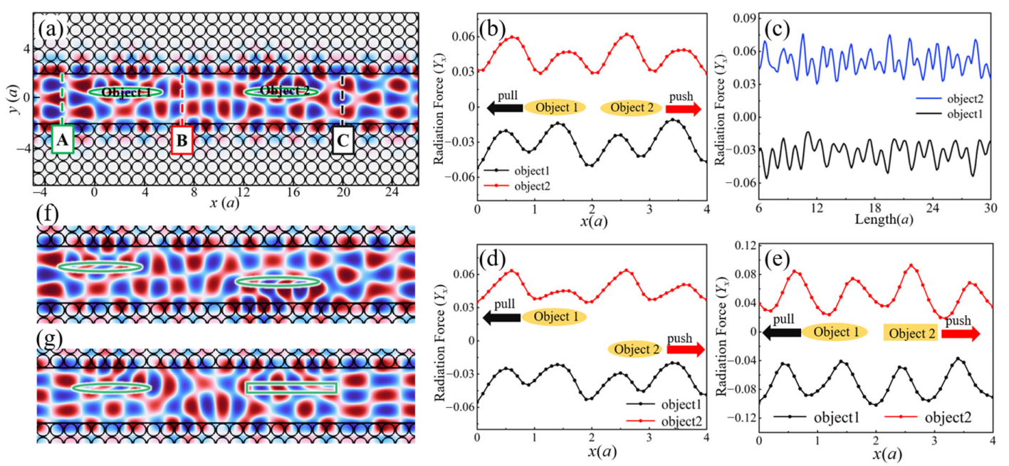
In addition, the separation of two identical objects can be achieved without relying on density and object size. Figure 4a shows the acoustic pressure field of the two same elliptical objects (rx = 2.8a, ry = 0.25a), which has the distance of L = 12.5a between the centers of objects 1 and 2. It can be observed that a relatively smaller mode is generated after scattering by object 1. However, the acoustic wave mode scattered by object 2 is reversed, which produces a relatively higher mode. Based on the conservation of momentum, we predict that the longitudinal acoustic force (Yx) exerted on object 1 is opposite to that of the acoustic wave that is propagating, and that on object 2 is the same as that of the wave that is propagating. The longitudinal acoustic force, Yx, is shown in Figure 4b. It is indicated that the ARF of Yx of object 1 is negative and that of object 2 is positive. The results show that two different manipulations can be achieved for two identical objects. When the distance between the center of object 1 and object 2 is different, the ARF will be affected, as shown in Figure 4c. The direction of the sound force does not change with the change in L. In order to observe the surprising ARF, the longitudinal acoustic force (Yx) acting on the two objects on the different y axes and different shapes is shown in Figure 4d,e. From Figure 4d, it is observed that the ARF of Yx exerted on object 1 (2.5a, 0.52a) is negative and that exerted on object 2 (15a, −0.52a) is positive; the acoustic pressure field is shown in Figure 4f. Furthermore, when object 2 changes to a rectangle (length lx = 6.4a, width ly = 0.59a), the ARF of Yx is still the opposite, as shown in Figure 4e; the acoustic pressure field is shown in Figure 4g. Therefore, we can achieve acoustic pulling and pushing concurrently in this PC waveguide that is not affected by the position and shape of the object. Our results will have potential advantages for the separation of identical particles in the field of particle separation.

4. Conclusions

In summary, an acoustic pulling force was achieved using the mode conversion mechanism in a phononic crystal waveguide that utilizes the momentum modulation characteristics of the periodic lattice for different eigenmodes. The advantages of our new mechanism over that of the traditional acoustic pulling method include long-range and stable pulling and the lack of requirements for the size of the object. We studied the band structures of the waveguide and calculated the acoustic radiation force acting on the object rigorously by integrating the Brillouin stress tensor. Moreover, the acoustic pulling force has a wide bandwidth and allows efficient and precise control over a wide range of sizes. For two identical objects, the efficient separation of them was achieved without relying on density and size, but by using mode conversion and reconversion. The principles and results reported in this work open up many possibilities for acoustic wave manipulation. The method is expected to become an important tool in diverse areas such as drug delivery, cell sorting and particle concentration determination.
In this work, assisted by 3D-printed scaffolders [45] and a traditional computer numerical control (CNC) machining process [50], the scheme proposed here was achieved. This scheme would be well worth studying.

Author Contributions

Conceptualization, Y.C. and W.D.; methodology, Y.G., T.Z. and D.T.; formal analysis and numerical simulation, Y.G., B.S., Q.J., W.G. and Y.Z.; data analysis, Y.G., Y.C., H.L. and W.D.; writing—original draft preparation, Y.G., X.L. and R.F.; writing—review and editing, Y.G., F.S. and W.D.; project administration, W.D.; funding acquisition, F.S. and W.D. All authors have read and agreed to the published version of the manuscript.

Funding

This work was supported by National Natural Science Foundation of China (Grant No. 12274105), Heilongjiang Natural Science Funds for Distinguished Young Scholar (Grant No. JQ2022A001), The Fundamental Research Funds for the Central Universities (HIT.OCEF.2021020, 2023FRFK06007), and the joint guidance project of Natural Science Foundation of Heilongjiang Province (Grant No. LH2023A006). The authors thank HPC Studio at the Physics School of Harbin Institute of Technology for providing access to computing resources through [email protected].

Data Availability Statement

Relevant data are available from the authors upon reasonable request.

Acknowledgments

We acknowledge the contribution of all the authors in the completion of this work.

Conflicts of Interest

The authors declare no conflict of interest.

References

  1. Khandurina, J.; Guttman, A. Bioanalysis in Microfluidic Devices. J. Chromatogr. A 2002, 943, 159–183. [Google Scholar] [CrossRef] [PubMed]
  2. Ozcelik, A.; Rufo, J.; Guo, F.; Gu, Y.; Li, P.; Lata, J.; Huang, T.J. Acoustic Tweezers for the Life Sciences. Nat. Methods 2018, 15, 1021–1028. [Google Scholar] [CrossRef] [PubMed]
  3. Chen, Z.; Segev, M. Highlighting Photonics: Looking into the next Decade. eLight 2021, 1, 2. [Google Scholar] [CrossRef]
  4. Cook, L.J.; Mazilu, D.A.; Mazilu, I.; Simpson, B.M.; Schwen, E.M.; Kim, V.O.; Seredinski, A.M. Cooperative Sequential-Adsorption Model in Two Dimensions with Experimental Applications for Ionic Self-Assembly of Nanoparticles. Phys. Rev. E 2014, 89, 062411. [Google Scholar] [CrossRef] [PubMed]
  5. Ashkin, A. Optical Trapping and Manipulation of Neutral Particles Using Lasers. Proc. Natl. Acad. Sci. USA 1997, 94, 4853–4860. [Google Scholar] [CrossRef] [PubMed]
  6. Kishimoto, T.; Masui, K.; Minoshima, W.; Hosokawa, C. Recent Advances in Optical Manipulation of Cells and Molecules for Biological Science. J. Photochem. Photobiol. C Photochem. Rev. 2022, 53, 100554. [Google Scholar] [CrossRef]
  7. Zhong, M.-C.; Wei, X.-B.; Zhou, J.-H.; Wang, Z.-Q.; Li, Y.-M. Trapping Red Blood Cells in Living Animals Using Optical Tweezers. Nat. Commun. 2013, 4, 1768. [Google Scholar] [CrossRef]
  8. Jonáš, A.; Zemánek, P. Light at Work: The Use of Optical Forces for Particle Manipulation, Sorting, and Analysis. Electrophoresis 2008, 29, 4813–4851. [Google Scholar] [CrossRef]
  9. Wen, F.; Zhang, X.; Ye, H.; Wang, W.; Wang, H.; Zhang, Y.; Dai, Z.; Qiu, C.-W. Efficient and Tunable Photoinduced Honeycomb Lattice in an Atomic Ensemble. Laser Photonics Rev. 2018, 12, 1800050. [Google Scholar] [CrossRef]
  10. Blázquez-Castro, A. Optical Tweezers: Phototoxicity and Thermal Stress in Cells and Biomolecules. Micromachines 2019, 10, 507. [Google Scholar] [CrossRef]
  11. Yu, P.; Liu, Y.; Zhao, Q.; Wang, Z.; Li, Y.-M.; Gong, L. Reducing Photodamage in Optical Trapping of Individual Cells in Living Zebrafish. Appl. Phys. Express 2020, 13, 032008. [Google Scholar] [CrossRef]
  12. Foo, J.-J.; Liu, K.-K.; Chan, V. Thermal Effect on a Viscously Deformed Liposome in a Laser Trap. Ann. Biomed. Eng. 2003, 31, 354–362. [Google Scholar] [CrossRef] [PubMed]
  13. Shan, X.; Wang, F.; Wang, D.; Wen, S.; Chen, C.; Di, X.; Nie, P.; Liao, J.; Liu, Y.; Ding, L.; et al. Optical Tweezers beyond Refractive Index Mismatch Using Highly Doped Upconversion Nanoparticles. Nat. Nanotechnol. 2021, 16, 531–537. [Google Scholar] [CrossRef] [PubMed]
  14. Zhu, Z.; Zhang, Y.; Zhang, S.; Adam, A.J.L.; Min, C.; Urbach, H.P.; Yuan, X. Nonlinear Optical Trapping Effect with Reverse Saturable Absorption. Adv. Photonics 2023, 5, 046006. [Google Scholar] [CrossRef]
  15. Zhang, P.; Rufo, J.; Chen, C.; Xia, J.; Tian, Z.; Zhang, L.; Hao, N.; Zhong, Z.; Gu, Y.; Chakrabarty, K.; et al. Acoustoelectronic Nanotweezers Enable Dynamic and Large-Scale Control of Nanomaterials. Nat. Commun. 2021, 12, 3844. [Google Scholar] [CrossRef] [PubMed]
  16. Wiklund, M. Acoustofluidics 12: Biocompatibility and Cell Viability in Microfluidic Acoustic Resonators. Lab. Chip 2012, 12, 2018–2028. [Google Scholar] [CrossRef] [PubMed]
  17. Hultström, J.; Manneberg, O.; Dopf, K.; Hertz, H.M.; Brismar, H.; Wiklund, M. Proliferation and Viability of Adherent Cells Manipulated by Standing-Wave Ultrasound in a Microfluidic Chip. Ultrasound Med. Biol. 2007, 33, 145–151. [Google Scholar] [CrossRef]
  18. Mohanty, S.; Khalil, I.S.M.; Misra, S. Contactless Acoustic Micro/Nano Manipulation: A Paradigm for next Generation Applications in Life Sciences. Proc. R. Soc. Math. Phys. Eng. Sci. 2020, 476, 20200621. [Google Scholar] [CrossRef]
  19. Zhu, H.; Zhang, P.; Zhong, Z.; Xia, J.; Rich, J.; Mai, J.; Su, X.; Tian, Z.; Bachman, H.; Rufo, J.; et al. Acoustohydrodynamic Tweezers via Spatial Arrangement of Streaming Vortices. Sci. Adv. 2021, 7, eabc7885. [Google Scholar] [CrossRef]
  20. Wu, M.; Ouyang, Y.; Wang, Z.; Zhang, R.; Huang, P.-H.; Chen, C.; Li, H.; Li, P.; Quinn, D.; Dao, M.; et al. Isolation of Exosomes from Whole Blood by Integrating Acoustics and Microfluidics. Proc. Natl. Acad. Sci. USA 2017, 114, 10584–10589. [Google Scholar] [CrossRef]
  21. Lakshmanan, A.; Jin, Z.; Nety, S.P.; Sawyer, D.P.; Lee-Gosselin, A.; Malounda, D.; Swift, M.B.; Maresca, D.; Shapiro, M.G. Acoustic Biosensors for Ultrasound Imaging of Enzyme Activity. Nat. Chem. Biol. 2020, 16, 988–996. [Google Scholar] [CrossRef] [PubMed]
  22. Dholakia, K.; Drinkwater, B.W.; Ritsch-Marte, M. Comparing Acoustic and Optical Forces for Biomedical Research. Nat. Rev. Phys. 2020, 2, 480–491. [Google Scholar] [CrossRef]
  23. Husseini, G.A.; Pitt, W.G.; Martins, A.M. Ultrasonically Triggered Drug Delivery: Breaking the Barrier. Colloids Surf. B Biointerfaces 2014, 123, 364–386. [Google Scholar] [CrossRef]
  24. Basha, S.A.; Salkho, N.; Dalibalta, S.; Husseini, G.A. Liposomes in Active, Passive and Acoustically-Triggered Drug Delivery. Mini Rev. Med. Chem. 2019, 19, 961–969. [Google Scholar] [CrossRef] [PubMed]
  25. Moradi Kashkooli, F.; Jakhmola, A.; Hornsby, T.K.; Tavakkoli, J.; Kolios, M.C. Ultrasound-Mediated Nano Drug Delivery for Treating Cancer: Fundamental Physics to Future Directions. J. Control. Release 2023, 355, 552–578. [Google Scholar] [CrossRef]
  26. Ding, X.; Lin, S.-C.S.; Kiraly, B.; Yue, H.; Li, S.; Chiang, I.-K.; Shi, J.; Benkovic, S.J.; Huang, T.J. On-Chip Manipulation of Single Microparticles, Cells, and Organisms Using Surface Acoustic Waves. Proc. Natl. Acad. Sci. USA 2012, 109, 11105–11109. [Google Scholar] [CrossRef] [PubMed]
  27. Yang, Y.; Yang, Y.; Liu, D.; Wang, Y.; Lu, M.; Zhang, Q.; Huang, J.; Li, Y.; Ma, T.; Yan, F.; et al. In-Vivo Programmable Acoustic Manipulation of Genetically Engineered Bacteria. Nat. Commun. 2023, 14, 3297. [Google Scholar] [CrossRef] [PubMed]
  28. Kolesnik, K.; Xu, M.; Lee, P.V.S.; Rajagopal, V.; Collins, D.J. Unconventional Acoustic Approaches for Localized and Designed Micromanipulation. Lab. Chip 2021, 21, 2837–2856. [Google Scholar] [CrossRef]
  29. Baudoin, M.; Thomas, J.-L.; Sahely, R.A.; Gerbedoen, J.-C.; Gong, Z.; Sivery, A.; Matar, O.B.; Smagin, N.; Favreau, P.; Vlandas, A. Spatially Selective Manipulation of Cells with Single-Beam Acoustical Tweezers. Nat. Commun. 2020, 11, 4244. [Google Scholar] [CrossRef]
  30. Terquem, A. KUNDT ET O. LEHMANN.—Ueber longitudinale Schwingungen and Klangfiguren in cylindrischen Flüssigkeitssaülen (Sur les vibrations longitudinales et les figures acoustiques dans les colonnes de liquides cylindriques); Annales de Poggendorff, t. CLIII, p. 1, 1874. J. Phys. Theor. Appl. 1876, 5, 159–161. [Google Scholar] [CrossRef]
  31. Meng, L.; Cai, F.; Chen, J.; Niu, L.; Li, Y.; Wu, J.; Zheng, H. Precise and Programmable Manipulation of Microbubbles by Two-Dimensional Standing Surface Acoustic Waves. Appl. Phys. Lett. 2012, 100, 173701. [Google Scholar] [CrossRef]
  32. Tang, Q.; Liu, P.; Guo, X.; Zhou, S.; Dong, Y. 2D Acoustofluidic Patterns in an Ultrasonic Chamber Modulated by Phononic Crystal Structures. Microfluid. Nanofluidics 2020, 24, 91. [Google Scholar] [CrossRef]
  33. Démoré, C.E.M.; Dahl, P.M.; Yang, Z.; Glynne-Jones, P.; Melzer, A.; Cochran, S.; MacDonald, M.P.; Spalding, G.C. Acoustic Tractor Beam. Phys. Rev. Lett. 2014, 112, 174302. [Google Scholar] [CrossRef] [PubMed]
  34. Baresch, D.; Thomas, J.-L.; Marchiano, R. Observation of a Single-Beam Gradient Force Acoustical Trap for Elastic Particles: Acoustical Tweezers. Phys. Rev. Lett. 2016, 116, 024301. [Google Scholar] [CrossRef] [PubMed]
  35. Mitri, F.G. Acoustical Pulling Force on Rigid Spheroids in Single Bessel Vortex Tractor Beams. Europhys. Lett. 2015, 112, 34002. [Google Scholar] [CrossRef]
  36. Fan, X.-D.; Zhang, L. Trapping Force of Acoustical Bessel Beams on a Sphere and Stable Tractor Beams. Phys. Rev. Appl. 2019, 11, 014055. [Google Scholar] [CrossRef]
  37. Xu, S.; Qiu, C.; Liu, Z. Transversally Stable Acoustic Pulling Force Produced by Two Crossed Plane Waves. Europhys. Lett. 2012, 99, 44003. [Google Scholar] [CrossRef]
  38. Meng, Y.; Li, X.; Liang, Z.; Ng, J.; Li, J. Acoustic Pulling with a Single Incident Plane Wave. Phys. Rev. Appl. 2020, 14, 014089. [Google Scholar] [CrossRef]
  39. Kushwaha, M.S.; Halevi, P.; Dobrzynski, L.; Djafari-Rouhani, B. Acoustic Band Structure of Periodic Elastic Composites. Phys. Rev. Lett. 1993, 71, 2022–2025. [Google Scholar] [CrossRef]
  40. Walker, E.L.; Jin, Y.; Reyes, D.; Neogi, A. Sub-Wavelength Lateral Detection of Tissue-Approximating Masses Using an Ultrasonic Metamaterial Lens. Nat. Commun. 2020, 11, 5967. [Google Scholar] [CrossRef]
  41. Kaya, O.A.; Cicek, A.; Ulug, B. Self-Collimated Slow Sound in Sonic Crystals. J. Phys. Appl. Phys. 2012, 45, 365101. [Google Scholar] [CrossRef]
  42. Jin, Y.; Walker, E.; Choi, T.-Y.; Neogi, A.; Krokhin, A. Simultaneous Negative Reflection and Refraction and Reverse-Incident Right-Angle Collimation of Sound in a Solid-Fluid Phononic Crystal. J. Acoust. Soc. Am. 2022, 151, 2723–2731. [Google Scholar] [CrossRef] [PubMed]
  43. Pennec, Y.; Vasseur, J.O.; Djafari-Rouhani, B.; Dobrzyński, L.; Deymier, P.A. Two-Dimensional Phononic Crystals: Examples and Applications. Surf. Sci. Rep. 2010, 65, 229–291. [Google Scholar] [CrossRef]
  44. Zhu, T.; Novitsky, A.; Cao, Y.; Mahdy, M.R.C.; Wang, L.; Sun, F.; Jiang, Z.; Ding, W. Mode Conversion Enables Optical Pulling Force in Photonic Crystal Waveguides. Appl. Phys. Lett. 2017, 111, 061105. [Google Scholar] [CrossRef]
  45. Korozlu, N.; Biçer, A.; Sayarcan, D.; Adem Kaya, O.; Cicek, A. Acoustic Sorting of Airborne Particles by a Phononic Crystal Waveguide. Ultrasonics 2022, 124, 106777. [Google Scholar] [CrossRef] [PubMed]
  46. Lighthill, M.J.; Newman, M.H.A. On Sound Generated Aerodynamically I. General Theory. Proc. R. Soc. Lond. Ser. Math. Phys. Sci. 1997, 211, 564–587. [Google Scholar] [CrossRef]
  47. Brillouin, L. Les tensions de radiation; Leur interprétation en mécanique classique et en relativité. J. Phys. Radium 1925, 6, 337–353. [Google Scholar] [CrossRef]
  48. Brillouin, L.; Brennan, R.O. Tensors in Mechanics and Elasticity. J. Appl. Mech. 1965, 32, 238. [Google Scholar] [CrossRef]
  49. Faridi, M.A.; Ramachandraiah, H.; Iranmanesh, I.; Grishenkov, D.; Wiklund, M.; Russom, A. MicroBubble Activated Acoustic Cell Sorting. Biomed. Microdevices 2017, 19, 23. [Google Scholar] [CrossRef]
  50. Ciampa, F.; Mankar, A.; Marini, A. Phononic Crystal Waveguide Transducers for Nonlinear Elastic Wave Sensing. Sci. Rep. 2017, 7, 14712. [Google Scholar] [CrossRef]
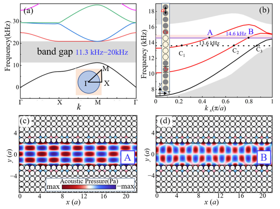
Figure 1. Mode conversion mechanism in phononic crystal (PC) waveguide structures. (a) The band structure of the PC without the waveguide. (b) The band structure of the PC waveguide; point A and point B represent two modes at a randomly selected frequency, 14.6 kHz (blue solid line), where the wave vectors of the two modes are kxA = 0.45 (π/a) and kxB = 0.79 (π/a). The gray circle is the copper column and the black dotted line is the defect. (c,d) The acoustic pressure field diagram at point A and point B. x = 0 is defined as a distance of 480 mm from the sound source, and y = 0 is defined as the symmetry center of the PC waveguide structure.
Photonics 10 01325 g001
Figure 2. Configurations of an ARF on the particle at an incident frequency of 14.6 kHz. (a) The detailed settings of the system, the object parameters: mass density, ρps = 1050 kg·m−3; longitudinal wave speed, cl = 2500 m·s−1; the semi-major axis, rx = 3.6a; and the semi-minor axis, ry = 0.34a. (b) The acoustic pressure field of an elliptic object (solid green line). (c) The acoustic pressure value (solid red line) for the y direction when there are no objects in the system. The lateral ARF (Yy) acting on the object, which is centered at x = 2a. (d) A black curve and red curve denoting the longitudinal ARF (Yx) exerted on the object located at y1 (0.52a) and y2 (−0.52a), respectively.
Photonics 10 01325 g002
Figure 3. Influence parameters of the ARF and acoustic pressure fields of the object. (a) The acoustic wave that is incident at a frequency of 14.6 kHz; the ARF of the object deviates from the stable point (0.52a) in the y direction and is located at 0.48a (black dashed line), 0.5a (red solid line), 0.55a (blue solid line) and 0.58a (green dashed line). (b) The acoustic pressure field of the object located at (1.5a, 0.5a) and (1.5a, 0.55a). (c) Different frequency incidents; objects subjected to ARF. (d) An ARF at (2.5a, 0.52a) for elliptic objects of different sizes (rx: from 0.1a to 8a; ry: from 0.1a to 0.8a). (eh) Acoustic pressure fields with different disturbances of A, B, C, and D points. The acoustic wave is still incident at the frequency of 14.6 kHz.
Photonics 10 01325 g003
Figure 4. Dual-object mode conversion mechanism. (a) The acoustic pressure field of object 1 (2.5a, 0.52a) and object 2 (2.5a + L, 0.52a) with L = 12.5a. The modes of A, B and C are mainly the fourth-order mode, third-order mode and fourth-order mode, respectively. (b) Graph showing that when L is 12.5a, the longitudinal acoustic force (Yx) exerted on object 1 is negative (the black curve), and that exerted on object 2 is positive (the red curve). (c) The ARF acting on the object when L changes from 6a to 30a. Object 1 is fixed at (1.5a, 0.52a). (d,e) The longitudinal acoustic force (Yx) acting on the two objects on the different y axes and different shapes. (f,g) The acoustic pressure field of two objects on the different y axes and different shapes.
Photonics 10 01325 g004
Disclaimer/Publisher’s Note: The statements, opinions and data contained in all publications are solely those of the individual author(s) and contributor(s) and not of MDPI and/or the editor(s). MDPI and/or the editor(s) disclaim responsibility for any injury to people or property resulting from any ideas, methods, instructions or products referred to in the content.