Article

Optical Helicity of Light in the Tight Focus

by
Alexey A. Kovalev
1,2,*,
Victor V. Kotlyar
1,2 and
Alexey M. Telegin
2
1
Image Processing Systems Institute of the RAS, Branch of FSRC “Crystallography & Photonics” of the RAS, 151 Molodogvardeyskaya St., 443001 Samara, Russia
2
Samara National Research University, 34 Moskovskoe Shosse, 443086 Samara, Russia
*
Author to whom correspondence should be addressed.
Photonics 2023, 10(7), 719; https://doi.org/10.3390/photonics10070719
Submission received: 8 June 2023 / Revised: 20 June 2023 / Accepted: 21 June 2023 / Published: 23 June 2023
(This article belongs to the Special Issue Correlation Optics)

Abstract

:
Using the Richards–Wolf formalism, we obtain explicit analytical expressions for the optical helicity density at the tight focus of four different light beams: a linearly polarized optical vortex, an optical vortex with right-handed circular polarization, superposition of a cylindrical vector beam and a linearly polarized beam, and a beam with hybrid circular-azimuthal polarization. We show that, in all four cases, the helicity density at the focus is nonzero and has different signs in different focal plane areas. If the helicity density changes sign, then the full helicity of the beam (averaged over the beam cross section at the focus) is zero and is conserved upon propagation. We reveal that the full helicity is zero when the full longitudinal component of the spin angular momentum is zero. If the helicity density does not change sign at the focus, such as in a circularly polarized optical vortex, then it is equal to the intensity in the focus, with the full helicity being equal to the beam power and conserving upon propagation. Although the helicity is related to the polarization state distribution across the beam at the focus, the expressions for the helicity density are found to be different from those for the longitudinal component of the spin angular momentum for the beams of interest.

1. Introduction

Optical helicity of circularly polarized light is characterized by a parameter σ = ±1, similar to the spin magnitude. A light field with left circular polarization has a helicity of h = −1, while a field with right circular polarization has a helicity of h = 1. For linearly polarized light, the helicity is zero, whereas for elliptically polarized light, the helicity modulus is less than unity. In the general form, the optical helicity was defined in several works (e.g., see [1,2,3]), while the magnetic helicity was considered back in 1958 [4]. The full helicity, defined based on the electromagnetic democracy principle, is given by
h ^ = 1 2 3 D ( A B C E ) d V , E = × C , B = × A ,
where E and B are the strength vectors of the electric and magnetic fields, and A and C are the electric and magnetic vector potentials. The helicity density is the integrand:
h = 1 2 ( A B C E )
The gauge transformation for the helicity is given by A A + f , C C + g , with f and g being arbitrary scalar functions. This transformation conserves the helicity since the curl of a gradient is zero.
The work [5] has shown a relation between the helicity and the chirality, with the latter density defined as
χ = ε 0 2 [ E ( × E ) + c 2 B ( × B ) ] ,
where ε0 is the vacuum electric permittivity, and c is the speed of light in a vacuum. As demonstrated in a general form in [6], full helicity and chirality are propagation invariants. The work in [7] has shown the difference between the helicity and the chirality. In a circularly polarized light field, each photon has a helicity of ± and a chirality of ± ω 2 / c , where is the Planck constant, and ω is the angular frequency. In [8], a general relation was considered between the helicity, chirality, and spin density. The helicity and spin densities are written as
h = 1 2 [ ε 0 μ 0 ( E ( × E ) ) + μ 0 ε 0 ( B ( × B ) ) ] , S = 1 2 [ ε 0 ( E × A ) + ( B × C ) ] ,
with μ0 being the vacuum permeability. In free space, for monochromatic light with angular frequency ω, the magnetic helicity is equal to the electric helicity, and thus the helicity in free space can be written in the following form [9]:
h = ε 0 μ 0 2 ω Im ( E * H ) ,
with H being the magnetic field strength vector in free space. Hereinafter, we use the above definition of the helicity density. Spin-to-orbit conversion, as discussed in [10], is also a matter of interest in this work thanks to the helicity property. In [9], the authors computed densities of some quantities (spin, energy flow, and helicity) for optical vortices propagating in various waveguides (planar waveguide, circular step-index waveguide). It was possible to carry out such an analysis as the components of the electric and magnetic field vectors of the modes of those waveguides are well known. The said work has prompted us to investigate the helicity at the tight focus of laser beams. Obtaining explicit expressions for space distributions of light field characteristics, such as the energy density (intensity), energy flow (Poynting vector), spin angular momentum (SAM), orbital angular momentum (OAM), helicity, and others, is an interesting and important problem, allowing these quantities to be analyzed without numerical simulation. For many vector light fields, the Richards–Wolf theory [11] allows deriving exact analytical expressions to describe all field characteristics near the focus.
In this work, we analyze four different initial vector fields and derive relationships for helicity densities in the initial plane and at the focus, as well as for full helicities. The full helicities are obtained by integration only over the beam section rather than over the whole space. We consider the following initial fields: a linearly polarized optical vortex, a circularly polarized optical vortex, superposition of a cylindrical vector beam and a linearly polarized beam, and a hybrid light field with circular-azimuthal polarization. Previously, based on the Richards–Wolf theory [11], expressions for all components of the electric and magnetic field vectors at the tight focus of all fields of interest have been derived [12,13,14,15,16]. Using these expressions for the light field components, we can derive analytical expressions for the helicity of these fields at the focus. In this work, we show that the helicity density at the focus is related to the longitudinal component of the SAM density. Note, however, that the full longitudinal SAM does not conserve when a light field passes through a spherical lens since, thanks to the spin-orbital conversion, the spin is partly converted to the OAM. On the contrary, the full helicity (helicity density averaged over the beam section) is the invariant and conserves upon free-space propagation and focusing of light.

2. Helicity at the Focus of a Linearly Polarized Optical Vortex

If the initial vector field is a linearly polarized optical vortex, its Jones vectors for the electric and magnetic field are given by
E ( θ , φ ) = A ( θ ) exp ( i n φ ) ( 1 0 ) , H ( θ , φ ) = A ( θ ) exp ( i n φ ) ( 0 1 ) ,
where φ is the azimuthal angle in the beam cross-section, θ is the angle between the optical axis and a line drawn from the focus center to a spherical wavefront point in the initial plane, n is integer topological charge of the optical vortex, and A(θ) is a circularly symmetric real-valued function defining the beam amplitude in the initial plane. Using a Richards–Wolf method [11], expressions were obtained in [12] for the intensity distribution and the SAM at the focus of field (1). For comparison purposes, below we give those expressions, analyzing them in relation to the helicity distribution at the focus of field (1), derived herein. The distributions of the intensity I = | E x | 2 + | E y | 2 + | E z | 2 and the longitudinal SAM component S z = 2 Im ( E x * E y ) are given by
I = 1 2 [ 2 I 0 , n 2 + I 2 , n + 2 2 + I 2 , n 2 2 + 2 I 1 , n + 1 2 + 2 I 1 , n 1 2 + + 2 cos ( 2 φ ) ( I 0 , n I 2 , n + 2 + I 0 , n I 2 , n 2 2 I 1 , n + 1 I 1 , n 1 ) ] ,
S z = 1 2 ( I 2 , n + 2 I 2 , n 2 ) ( I 2 , n + 2 + I 2 , n 2 + 2 cos ( 2 φ ) I 0 , n )
Equations (2) and (3) contain functions Iν,μ that depend only on the radial and longitudinal variables r and z:
I ν , μ = 2 k f 0 α sin ν + 1 ( θ 2 ) cos 3 ν ( θ 2 ) cos 1 / 2 ( θ ) A ( θ ) e i k z cos θ J μ ( k r sin θ ) d θ ,
where k = 2π/λ is the wavenumber of monochromatic light of wavelength λ; f is the lens focal length; α is the maximal tilt angle of light rays to the optical axis, which defines the numerical aperture of an aplanatic lens, NA = sin α; and Jµ(kr sin θ) is the µth-order Bessel function of the first kind. In Equation (3) and throughout the paper, the indices ν and µ can take the following values: ν = 0, 1, 2; µ = n − 2, n − 1, n, n + 1, n + 2.
Further, we obtain the helicity distribution at the focus of field (1) using the helicity definition from [9]:
h = ε 0 μ 0 2 ω Im ( E * H )
where ε0 and μ0 are the vacuum electric permittivity and the vacuum magnetic permeability, ω is the angular frequency of light, and E and H are the electric and magnetic field vectors. Below, we omit the constant ε 0 μ 0 / ( 2 ω ) for brevity. We note that the helicity (5) has the same dimension as the SAM (3). Using expressions for the components of the electric and magnetic vectors at the focus of field (1), derived in [12], Equation (5) is rearranged to
h ( r ) = 1 2 ( I 2 , n + 2 2 I 2 , n 2 2 + 2 I 1 , n + 1 2 2 I 1 , n 1 2 )
As seen from Equation (6), the helicity distribution is circularly symmetric. We note that despite zero helicity of field (1) in the initial plane (h = 0), in the focal plane, the helicity has a nonzero density (helicity at each point of the beam cross-section). Comparison of Equations (3) and (6) indicates that if the numerical apertures are small, i.e., when the longitudinal field component can be neglected ( 2 | I 1 , n + 1 2 I 1 , n 1 2 | < < 1 ), the helicity coincides with the longitudinal SAM (3) at the polar angles φ = π / 4 + π p / 2 (p = 0, 1, 2, 3), at which cos 2φ = 0. Then, the helicity and the SAM coincide: h = Sz. From Equation (3), it follows that if n = −2, then the light is right-handed elliptically polarized near the optical axis, and the positive helicity is equal to the SAM, coinciding with the intensity: h ( r = 0 ) = S z ( r = 0 ) = I ( r = 0 ) = I 1 , 0 2 / 2 > 0 . Vice versa at n = 2, the helicity and the SAM are negative at the focus center: h ( r = 0 ) = S z ( r = 0 ) = I 1 , 0 2 / 2 < 0 . Thus, the helicity sign coincides with the SAM sign, or in other words, the helicity is positive in focal regions with right-handed elliptic polarization, being negative in focal regions with left-handed elliptic polarization. The difference between the helicity and the SAM is that at n = 1 or n = −1, the on-axis helicity (6) is nonzero, whereas the on-axis SAM (3) is zero. Thus, the helicity (6) is not only related to spin and indicates focal areas with left- or right-handed elliptic polarization, but also indicates the transverse helicity of the focal field related to the longitudinal component of the electric field vector. It can be shown that the full helicity, averaged over the beam cross-section, equals zero and conserves upon focusing. Indeed, as shown in [13], the following expression holds:
W ν , μ = 2 π 0 | I v , μ ( r ) | 2 r d r = 4 π f 2 0 α sin 2 ν + 1 ( θ 2 ) cos 5 2 v ( θ 2 ) | A ( θ ) | 2 d θ = W ν .
From Equation (7), we get the averaged helicity:
h ^ = 0 0 2 π h ( r ) r d r d φ = 1 2 0 0 2 π ( I 2 , n + 2 2 I 2 , n 2 2 + 2 I 1 , n + 1 2 2 I 1 , n 1 2 ) r d r d φ = 1 2 ( W 2 W 2 + 2 W 1 2 W 1 ) = 0 .
The full longitudinal SAM, averaged over the focal plane based on Equation (3), is also zero:
S ^ z = 1 2 0 0 2 π r d r d φ ( I 2 , n + 2 I 2 , n 2 ) ( I 2 , n + 2 + I 2 , n 2 + 2 cos ( 2 φ ) I 0 , n ) = W 2 W 2 = 0 .

3. Helicity at the Focus of a Circularly Polarized Optical Vortex

In this section, we investigate the helicity at the focus of a circularly polarized optical vortex in a similar way. The Jones vectors for the initial electric and magnetic fields read as
E ( θ , φ ) = A ( θ ) 2 exp ( i n φ ) ( 1 i ) , H ( θ , φ ) = A ( θ ) 2 exp ( i n φ ) ( i 1 ) .
The amplitudes in the initial field (10) are given for right circular polarization. In the initial plane, the longitudinal SAM component of field (10) equals S z = A 2 ( θ ) , whereas the full spin in the initial plane is equal to the full beam energy:
S ^ z = 2 π 0 0 2 π A 2 ( θ ) r d r = W
In [14], adopting the Richards–Wolf method [11], expressions were obtained for the intensity and the longitudinal SAM component at the focus. We write these expressions here for a comparison with a helicity expression that is derived below. Distributions of the intensity and the longitudinal SAM component at the focus of field (10) are given by
I ( r , φ ) = | E x | 2 + | E y | 2 + | E z | 2 = I 0 , n 2 + I 2 , n + 2 2 + 2 I 1 , n + 1 2 ,
S z = 2 Im ( E x * E y ) = I 0 , n 2 I 2 , n + 2 2 .
Due to the circular polarization of the initial field, both the intensity distribution (12) and the spin density distribution (13) have circular symmetry at the focus. The helicity distribution (5) at the focus of field (10) is equal to the intensity:
h R ( r ) = I ( r ) = I 0 , n 2 + I 2 , n + 2 2 + 2 I 1 , n + 1 2 .
Similar to Equation (8), the full helicity of beam (10) at the focus is given by
h ^ R = 0 0 2 π h R ( r ) r d r d φ = W = 0 0 2 π ( I 0 , n 2 + I 2 , n + 2 2 + 2 I 1 , n + 1 2 ) r d r d φ = W 0 + W 2 + 2 W 1 ,
with W being the total beam power/energy. The full longitudinal SAM component at the focus of field (10) is given by
S ^ z = 0 0 2 π r d r d φ ( I 0 , n 2 I 2 , n + 2 2 ) = W 0 W 2 .
In the initial plane, the helicity density and the full helicity of field (10) read as
h 0 R ( r ) = | A ( θ ) | 2 , h ^ 0 R = W .
A comparison of Equations (15) and (17) reveals that the full helicity conserves upon focusing, which is in contrast with the full spin. As seen from a comparison of Equations (11) and (16), the full spin is not conserved. Instead, it decreases and, due to the spin-orbit conversion, the spin is partly transferred to the OAM.
It can also be seen that for circular polarization, the helicity achieves its maximal value and equals the beam power. For left circular polarization, the helicity in the initial plane and at the focus changes sign:
h L ( r ) = I ( r ) = ( I 0 , n 2 + I 2 , n 2 2 + 2 I 1 , n 1 2 ) , h 0 L ( r ) = | A ( θ ) | 2 , h ^ 0 L = h ^ L = W , r = f sin θ ,
We note that the on-axis helicity magnitude depends on the topological charge and, with increasing modulus of n, decays from the maximum (at n = 0) to zero (at n > 2 or n < −2):
h R ( r = 0 ) = I 0 , 0 2 , n = 0 , h R ( r = 0 ) = I 2 , 0 2 , n = 2 , h R ( r = 0 ) = 2 I 1 , 0 2 , n = 1 , h R ( r = 0 ) = 0 , | n | > 2 .
The full helicity for the circularly polarized optical vortex is independent of the topological charge n and equal to the beam power, W, for right-handed circular polarization, taking the opposite sign, −W, for left-handed circular polarization.

4. Helicity at the Focus of a Cylindrical Vector Beam

In the initial plane, a high-order cylindrical vector beam has the following Jones vectors:
E ( θ , φ ) = A ( θ ) ( cos m φ sin m φ ) , H ( θ , φ ) = A ( θ ) ( sin m φ cos m φ ) .
As shown in [15], the longitudinal component Sz of the SAM vector at the focus of field (20) is zero. It can be shown that the helicity density and the full helicity in the initial plane (20) and at the focus is also zero (h(r) = 0). However, if the cylindrical vector field (20) is coherently superimposed with a linearly polarized field, we obtain an initial light field
E ( θ , φ ) = A ( θ ) ( cos m φ a sin m φ ) , H ( θ , φ ) = A ( θ ) ( sin m φ cos m φ a ) ,
with a nonzero helicity density at the focus. Indeed, in [16], analytical expressions were obtained for the electric and magnetic field components at the focus of the initial field (21). Using these expressions and the definition in (5), we can derive a formula for the helicity density at the focus of field (21):
h ( r , φ ) = { 2 a ( 1 ) p ( I 0 , 0 I 0 , m + I 2 , 2 I 2 , m 2 2 I 1 , 1 I 1 , m 1 ) sin ( m φ ) ,   m = 2 p + 1 , 0 ,   m = 2 p .
According to Equation (22), the helicity of a cylindrical vector beam at the focus is nonzero only for an odd order (m = 2p + 1). We note that at the focus of beam (20), the spin density is also nonzero only for an odd order m = 2p + 1 [16]:
S z ( r , φ ) = { 2 a ( 1 ) p [ sin ( ( m 2 ) φ ) ( I 0 , 0 I 2 , m 2 I 2 , 2 I 0 , m ) sin ( m φ ) ( I 0 , 0 I 0 , m I 2 , 2 I 2 , m 2 ) ] , m = 2 p + 1 , 0 , m = 2 p , p = 0 , 1 , 2 ,
A comparison of Equations (22) and (23) indicates that the helicity changes sign in approximately the same areas of the focal spot at which the spin density changes sign, since both quantities depend on sin(). In any case, with the terms with I0,0I0,m contribute the most [13], and the magnitudes h and Sz have the same sign. The difference is, in particular, that the expression for the helicity in (22) includes the longitudinal component of the electric field, whereas the spin density in (23) includes only the transverse components of the electric field. The full helicity h ^ , i.e., the helicity density (22) averaged over the focal plane, as well as the full spin S ^ z , i.e., the averaged spin density (23), are both equal to zero ( h ^ = S ^ z = 0 ), since the integrals over the polar angle in Equations (22) and (23) yield zeros.

5. Helicity at the Focus of a Field with Hybrid Circular-Azimuthal Polarization

Here, we consider the tight focusing of light with initial hybrid circular-azimuthal polarization. At different polar angles, polarization of this field changes from linear to elliptic and to circular polarization. The Jones vectors of the initial electric and magnetic fields of such a hybrid field read as
E ( θ , φ ) = A ( θ ) ( i sin ( m φ ) cos ( m φ ) ) , H ( θ , φ ) = A ( θ ) ( cos ( m φ ) i sin ( m φ ) ) .
The initial field (24) has the spin density equal to S z = A 2 ( θ ) sin ( 2 m φ ) , whereas the full spin, averaged over the entire beam section, is equal to zero:
S ^ z = 0 0 2 π A 2 ( θ ) sin ( 2 m φ ) r d r d φ = 0 .
As shown in [17], at the focus of field (24), the density of the longitudinal component of the SAM vector is nonzero and reads as
S z = 1 4 [ I 0 , m ( I 2 , m + 2 I 2 , m 2 ) sin 2 φ + ( I 0 , m 2 I 2 , m 2 I 2 , m + 2 ) sin ( 2 m φ ) ] .
According to Equation (7), the full longitudinal component of the SAM vector is zero:
S ^ z = 1 4 0 0 2 π r d r d φ [ I 0 , m ( I 2 , m + 2 I 2 , m 2 ) sin 2 φ + ( I 0 , m 2 I 2 , m 2 I 2 , m + 2 ) sin ( 2 m φ ) ] = 0
The integrals over the angle are equal to zero in Equations (25) and (27), since the integration of the periodic function is done over an integer number of periods. From Equations (25) and (27) it follows that the full spin is zero and conserves upon focusing. Using the components of the strength vectors of field (24) at the focus, computed in [17], an expression can be obtained for the helicity density:
h = ( I 0 , m 2 + I 2 , m + 2 I 2 , m 2 2 I 1 , m + 1 I 1 , m 1 ) sin ( 2 m φ )
As seen from Equation (28), the helicity, as the SAM (26), changes sign 4m times along a certain-radius circle around the optical axis. Since the terms with I 0 , m 2 contribute the most [13], approximate expressions for the SAM (26) and for the helicity (28) are almost identical and equal to S z h I 0 , m 2 sin ( 2 m φ ) . From Equation (28), it also follows that the full helicity at the focus is zero, like the full spin in Equation (27). In the initial plane of field (24), the helicity density is also coincident with the longitudinal SAM density: h = S z = A 2 ( θ ) sin ( 2 m φ ) , whereas the full helicity and the full SAM in the initial plane are equal to zero: h ^ = S ^ z = 0 . Thus, the full helicity and the full longitudinal SAM component are zero and conserve upon focusing.

6. Numerical Simulation

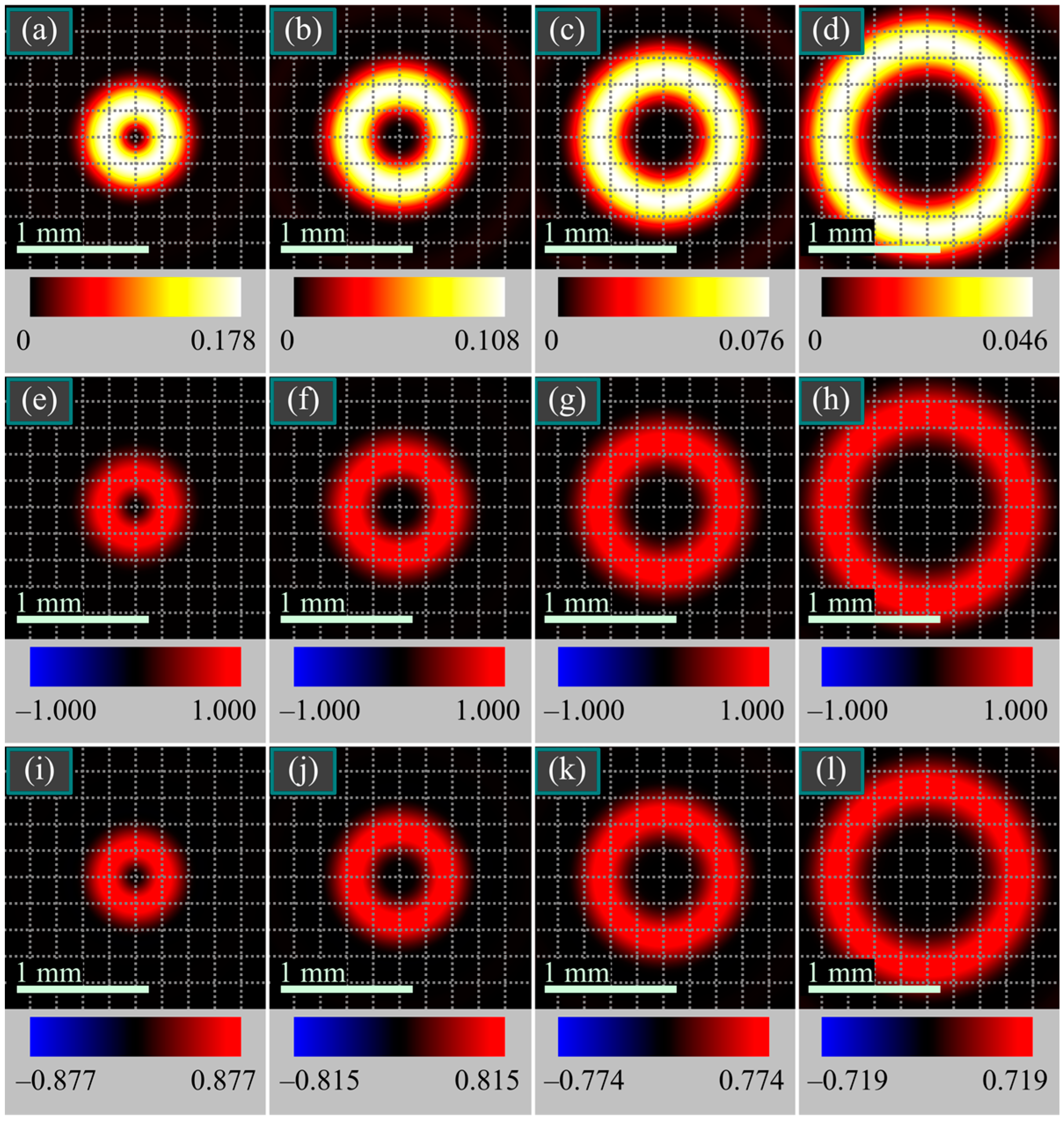
Shown in Figure 1 are the intensity, helicity, and SAM density distributions for linearly polarized beam (1) at the tight focus for different values of the topological charge. The helicity and SAM density distributions in Figure 1 and in all the figures below are obtained by formulae S z = 2 Im ( E x * E y ) and h = Im ( E * H ) with the components of the strength vectors E and H obtained using the Richards–Wolf formulae, as well as Equations (6) and (3). The computed images are visually indistinguishable.
As seen from Figure 1, indeed, in contrast to the SAM density, the helicity distribution is circularly symmetric. In any case, Figure 1 confirms the negative helicity in the focus center at n = 2, as well as the nonzero helicity on the optical axis at n = ±1.
Figure 2 also illustrates the intensity, helicity, and SAM density distributions at the tight focus for different values of the topological charge, but for a beam with right circular polarization (10).
Figure 2 confirms that if the initial field is circularly polarized, then the intensity, helicity, and the SAM density distributions at the focus are circularly symmetric. In addition, Figure 2 demonstrates that the helicity distribution at the focus coincides with the intensity distribution. The maximal helicity value is equal to the maximal intensity value, whereas the maximal SAM density value is smaller due to the spin-orbit conversion, when the SAM is partly converted into the OAM. Nevertheless, the maximal SAM density value is much higher than when the initial field is linearly polarized (Figure 1).
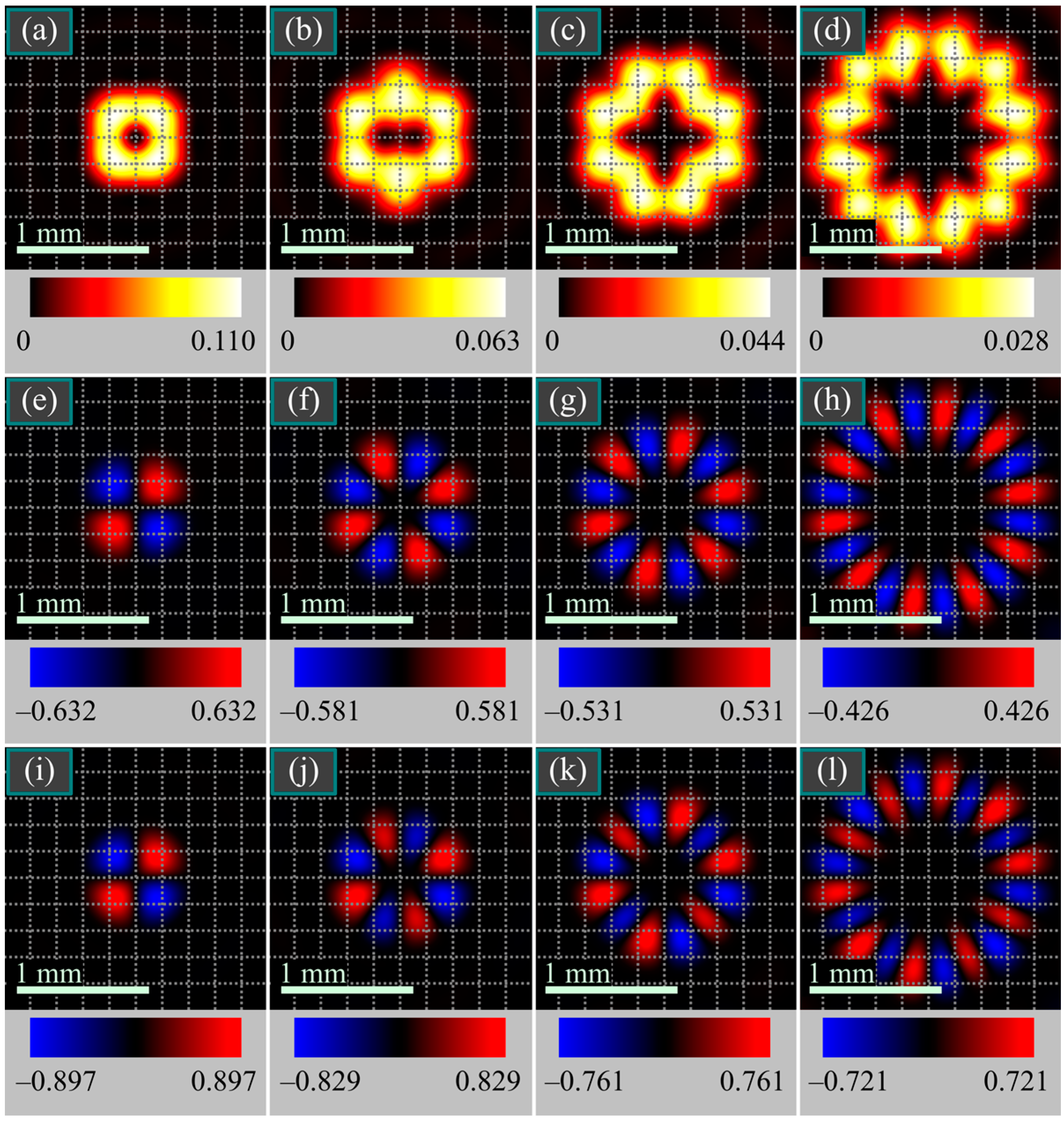
Shown in Figure 3 are the intensity, helicity, and SAM density distributions at the tight focus for different values of the polarization singularity index for the superposition of two beams with cylindrical and linear polarization states (21).
According to Figure 3, the helicity and the SAM density at the focus are indeed nonzero only for an odd-order cylindrical vector beam, m = 2p + 1. It is also seen that the helicity changes sign at near-same polar angles in the focal plane, as does the SAM density (the outer rings in Figure 3g,k and Figure 3h,l).
Finally, Figure 4 demonstrates the intensity, helicity, and SAM density distributions at the tight focus for different values of the polarization singularity index but for a beam with hybrid circular-azimuthal polarization (24).
As Figure 4 reveals, in contrast to the superposition of beams with cylindrical and linear polarization, the helicity and the SAM at the focus change sign 4m, rather than 2m, times along a certain-radius circle around the optical axis. In any case, Figure 4 also confirms that if the numerical aperture is high enough, then the approximate expressions for the SAM and for the helicity are very similar.
Thus, the numerical simulation confirms the theoretical expressions and the properties of the helicity and the SAM density. As seen in Figure 1, Figure 2, Figure 3 and Figure 4, much greater values of the helicity and the SAM density are achieved for fields that are nonlinearly polarized in the initial plane, as is the case for the circularly polarized beams (Figure 2) and beams with hybrid circular-azimuthal polarization (Figure 4).

7. Conclusions

For four different vector fields, we have obtained exact expressions for the helicity density at the tight focus. The expressions derived are similar to the expressions for the longitudinal SAM component at the focus, with the difference being that the helicity expressions include terms consisting of angular harmonics that are present only in the longitudinal components of the field strength vectors. If the full SAM in the initial plane is zero, then it conserves upon propagation and equals zero at the focus. In this case, the full helicity in the initial plane and in the focus is also zero and conserves upon focusing. If, however, the full SAM in the initial plane is nonzero, then it does not conserve upon focusing but is partially converted to the longitudinal OAM component due to the spin-orbit conversion. In this case, the full helicity is also nonzero but conserves upon focusing. This means that the helicity, like the beam power, is propagation invariant. For a circularly polarized vortex, the full helicity achieves a maximal value and is equal in magnitude to the full beam energy/power.
Similar to the Poynting vector components (energy flow), measuring the helicity density in practice is also challenging. The longitudinal component of the spin density Sz can be measured by using a well-known technique of determining the Stokes vector components [18,19] since the longitudinal component of the spin density is equal to the third component of the Stokes vector S3. However, determining the helicity density h [20,21], as well as the Poynting vector components, requires knowing the amplitude and phase of the electric and magnetic field components [22,23]. Transverse and longitudinal components of the spin density vector were investigated in an interesting study [24] for plasmons propagating on a cylindrical or conical surface. The helicity density in this work was considered as a spin density.

Author Contributions

Conceptualization, V.V.K.; methodology, V.V.K.; software, A.A.K. and A.M.T.; validation, V.V.K. and A.A.K.; formal analysis, V.V.K.; investigation, V.V.K. and A.A.K.; resources, V.V.K.; data curation, V.V.K.; writing—original draft preparation, V.V.K.; writing—review and editing, V.V.K.; visualization, A.A.K. and A.M.T.; supervision, V.V.K.; project administration, V.V.K.; funding acquisition, V.V.K. All authors have read and agreed to the published version of the manuscript.

Funding

This work was partly funded by the Russian Science Foundation under grant No. 23-12-00236 (Theoretical background). This work was also performed within the State assignment of Federal Scientific Research Center “Crystallography and Photonics” of Russian Academy of Sciences (Simulation).

Institutional Review Board Statement

Not applicable.

Informed Consent Statement

Not applicable.

Data Availability Statement

Not applicable.

Conflicts of Interest

The authors declare no conflict of interest. The funders had no role in the design of the study; in the collection, analyses, or interpretation of data; in the writing of the manuscript; or in the decision to publish the results.

References

  1. Afanasiev, G.N.; Stepanovsky, Y.P. The helicity of the free electromagnetic field and its physical meaning. Nuov. Cim. A 1996, 109, 271–279. [Google Scholar] [CrossRef] [Green Version]
  2. Trueba, J.L.; Racada, A.F. The electromagnetic helicity. Eur. J. Phys. 1996, 17, 141–144. [Google Scholar] [CrossRef]
  3. Cameron, R.P.; Barnett, S.M.; Yao, A.M. Optical helicity, optical spin and related quantities in electromagnetic theory. New J. Phys. 2012, 14, 053050. [Google Scholar] [CrossRef]
  4. Woltjer, L. A theorem on force-free magnetic fields. Proc. Natl Acad. Sci. USA 1958, 44, 489–491. [Google Scholar] [CrossRef] [Green Version]
  5. Crimin, F.; Mackinnon, N.; Gцtte, J.B.; Barnett, S.M. Optical helicity and chirality: Conservation and sources. Appl. Sci. 2019, 9, 828. [Google Scholar] [CrossRef] [Green Version]
  6. Lipkin, D.M. Existence of a new conservation law in electromagnetic theory. J. Math. Phys. 1964, 5, 696–700. [Google Scholar] [CrossRef]
  7. Mackinnon, N. On the differences between helicity and chirality. J. Opt. 2019, 21, 125402. [Google Scholar] [CrossRef]
  8. Aiello, A. Helicity, chirality, and spin of optical fields without vector potentials. Phys. Rev. A 2022, 106, 043519. [Google Scholar] [CrossRef]
  9. Abujetas, D.R.; Sбnchez-Gil, J.A. Spin angular momentum of guided light induced by transverse confinement and intrinsic helicity. ACS Photonics 2020, 7, 534–545. [Google Scholar] [CrossRef]
  10. Bliokh, K.Y.; Bekshaev, A.Y.; Nori, F. Extraordinary momentum and spin in evanescent waves. Nat. Commun. 2014, 5, 3300. [Google Scholar] [CrossRef] [PubMed] [Green Version]
  11. Richards, B.; Wolf, E. Electromagnetic diffraction in optical systems, II. Structure of the image field in an aplanatic system. Proc. R. Soc. Lond A 1959, 253, 358–379. [Google Scholar] [CrossRef]
  12. Kotlyar, V.V.; Kovalev, A.A.; Kozlova, E.S.; Telegin, A.M. Hall Effect at the Focus of an Optical Vortex with Linear Polarization. Micromachines 2023, 14, 788. [Google Scholar] [CrossRef]
  13. Kovalev, A.A.; Kotlyar, V.V. Spin Hall Effect of Double-Index Cylindrical Vector Beams in a Tight Focus. Micromachines 2023, 14, 494. [Google Scholar] [CrossRef] [PubMed]
  14. Kotlyar, V.V.; Nalimov, A.G.; Stafeev, S.S. Exploiting the circular polarization of light to obtain a spiral energy flow at the subwavelength focus. J. Opt. Soc. Am. B 2019, 36, 2850–2855. [Google Scholar] [CrossRef]
  15. Kotlyar, V.V.; Stafeev, S.S.; Kovalev, A.A.; Zaitsev, V.D. Spin Hall Effect before and after the Focus of a High-Order Cylindrical Vector Beam. Appl. Sci. 2022, 12, 12218. [Google Scholar] [CrossRef]
  16. Kotlyar, V.; Stafeev, S.; Zaitsev, V.; Kozlova, E. Spin-Orbital Conversion with the Tight Focus of an Axial Superposition of a High-Order Cylindrical Vector Beam and a Beam with Linear Polarization. Micromachines 2022, 13, 1112. [Google Scholar] [CrossRef]
  17. Kotlyar, V.V.; Stafeev, S.S.; Zaitsev, V.D.; Kovalev, A.A. Multiple optical spin-orbit Hall effect at the tight focus. Phys. Lett. A 2023, 458, 128596. [Google Scholar] [CrossRef]
  18. Berry, H.G.; Gabrielse, G.; Livingston, A.E. Measurement of the Stokes parameters of light. Appl. Opt. 1977, 16, 3200–3205. [Google Scholar] [CrossRef] [Green Version]
  19. D’yachkov, N.V.; Bogatov, A.P. Measuring the Stokes parameters of radiation of semiconductor lasers. Quantum Electron. 2011, 41, 869–874. [Google Scholar] [CrossRef]
  20. Forbes, K.A.; Jones, G.A. Measures of helicity and chirality of optical vortex beams. J. Opt. 2021, 23, 115401. [Google Scholar] [CrossRef]
  21. Koksal, K.; Babiker, M.; Lembessis, V.E.; Yuan, J. Chirality and helicity of linearly-polarised Laguerre-Gaussian beams of small beam waists. Opt. Commun. 2021, 490, 126907. [Google Scholar] [CrossRef]
  22. Litvin, I.A. The behavior of the instantaneous Poynting vector of symmetrical laser beams. J. Opt. Soc. Am. A 2012, 29, 901–907. [Google Scholar] [CrossRef] [PubMed]
  23. Leach, J.; Keen, S.; Padgett, M.J.; Saunter, C.; Love, G.D. Direct measurement of the skew angle of the Poynting vector in a helically phased beam. Opt. Express 2006, 14, 11919–11924. [Google Scholar] [CrossRef] [PubMed] [Green Version]
  24. Garoli, D.; Zilio, P.; De Angelis, F.; Gorodetski, Y. Helicity locking of chiral light emitted from a plasmonic nanotaper. Nanoscale 2017, 9, 6965–6969. [Google Scholar] [CrossRef]
Figure 1. Intensity (ad), helicity (eh), and SAM density (il) distributions of linearly polarized optical vortex (1) at the tight focus for the following parameters: wavelength λ = 532 nm; focal length of the lens f = 10 μm; numerical aperture of the lens NA = 0.95; topological charges n = 1 (a,e,i), 2 (b,f,j), 3 (c,g,k), 5 (d,h,l); and radial amplitude function A(θ) ≡ 1 (plane beam). The numbers near the color bars under each figure denote the maximal and minimal values. Maximal intensity values are given in relative units and are proportional to the maximal intensities for different topological charges. Maximal values of the helicity and the SAM density are normalized to the maximal intensity values.
Photonics 10 00719 g001
Figure 2. Intensity (ad), helicity (eh), and SAM density (il) distributions of an optical vortex with right circular initial polarization (10) at the tight focus for the following parameters: wavelength λ = 532 nm; focal length of the lens f = 10 μm; numerical aperture of the lens NA = 0.95; topological charges n = 1 (a,e,i), 2 (b,f,j), 3 (c,g,k), 5 (d,h,l); and radial amplitude function A(θ) ≡ 1 (plane beam). The numbers near the color bars under each figure denote the maximal and minimal values. Maximal intensity values are given in relative units and are proportional to the maximal intensities for different topological charges. Maximal values of the helicity and of the SAM density are normalized to the maximal intensity values.
Photonics 10 00719 g002
Figure 3. Intensity (ad), helicity (eh), and SAM density (il) distributions of superposition of beams with cylindrical and linear polarization (21) at the tight focus for the following parameters: wavelength λ = 532 nm; focal length of the lens f = 10 μm; lens numerical aperture, NA = 0.95; polarization singularity index m = 1 (a,e,i), 2 (b,f,j), 3 (c,g,k), 5 (d,h,l); radial amplitude function A(θ) ≡ 1 (plane beam); and amplitude of the linearly polarized term a = 0.5. The numbers near the color bars under each figure denote the maximal and minimal values. Maximal intensity values are given in relative units and are proportional to the maximal intensities for different index. Maximal values of the helicity and of the SAM density are normalized to the maximal intensity values.
Photonics 10 00719 g003
Figure 4. Intensity (ad), helicity (eh), and SAM density (il) distributions of a beam with hybrid circular-azimuthal initial polarization (24) at the tight focus for the following parameters: wavelength λ = 532 nm; focal length of the lens f = 10 μm; numerical aperture of the lens NA = 0.95; polarization singularity index m = 1 (a,e,i), 2 (b,f,j), 3 (c,g,k), 5 (d,h,l); and radial amplitude function A(θ) ≡ 1 (plane beam). The numbers near the color bars under each figure denote the maximal and minimal values. Maximal intensity values are given in relative units and are proportional to the maximal intensities for different topological charges. The maximal values of the helicity and SAM density are normalized to the maximal intensity values.
Photonics 10 00719 g004
Disclaimer/Publisher’s Note: The statements, opinions and data contained in all publications are solely those of the individual author(s) and contributor(s) and not of MDPI and/or the editor(s). MDPI and/or the editor(s) disclaim responsibility for any injury to people or property resulting from any ideas, methods, instructions or products referred to in the content.