Abstract
In this paper, we study the features of the resonant response of a system consisting of two subwavelength one-dimensional periodic structures, considering the dispersion of the refractive index in the presence of optical PT-symmetry for TM polarization. For the considered structure in the green wavelength range, two possible resonance lines were identified at 514.86 nm and 518.5 nm. Ultra-narrow resonances (FWHM of 0.00015 nm) have been obtained for transmitted and reflected waves, and a significant enhancement of the resonant response has been achieved (up to 105 times). The dependence of the system’s optical response on the relative position of its two sub-wavelength gratings and the magnitude of the amplification coefficient of the active part was investigated. This can be used to tune the spectral characteristics of filters, modulate the optical radiation, and create optomechanical sensors such as strain gauges.
1. Introduction
The resonant properties of periodic structures have been intensively studied since work began on Wood’s anomalies [1], which received the most complete theoretical description in [2]. The development of the topic of the resonant properties of diffractive periodic structures received another boost in the 1990s, based on the intensive development of waveguides and integrated optics technologies, and in particular, research in the field of optical filtering [3,4]. The papers [5,6,7,8,9] describe in detail the theoretical approaches used to describe the periodic structures under study, and obtain results on the use of these structures for filtering electromagnetic radiation in transmitted and reflected radiation due to the excitation of waveguide modes along the periodic structure. Resonant grating reflection filters can achieve symmetrical line shapes with spectral linewidths on the order of angstroms and reflection efficiencies approaching 100% [10,11]. Further interest in subwavelength resonant structures has been raised by the technological progress made in the field of nanolithography, material structuring and further developments in widespread applications in integrated optics [11], including the creation of the latest generation of biosensors [12,13,14,15], color structuring technology [16], and the study and use of nonlinear [17,18] and nonlocal response [19] of resonant periodic structures.
Notice that periodic structures in the form of subwavelength gratings—structures whose period is too small to observe diffraction effects (the period of the structures is less than the wavelength of the radiation incident on them)—constitute a separate class of optical devices [20]. The general feature of a subwavelength periodic structure is that the subwavelength grating works as a waveguide made of a complementary birefringent material, the refractive index and dispersion of which depend on the period and geometry of the grating [21]. Moreover, when working in the “near field” mode, the waveguide leaky mode in turn couples light back to a radiated mode producing potentially strong back-reflections from the grating surface propagating along the grating in opposite directions [22]. This phenomenon is also referred to as guided mode resonance, which makes it possible to significantly reduce losses due to the absence of diffraction losses, obtain a resonant response in the reflection and transmission of light depending on the angle of incidence, have polarization selectivity and have a reflection coefficient close to 100% [20] in a wide spectral range, which is also ideal for scattering engineering [23]. As a result, subwavelength gratings have found many applications in free optics: reflectors and filters [24,25], as well as birefringent optics and polarizers [26,27]. Separately, the use of subwavelength gratings to engineer/tailor the dispersion response and nonlinear properties should be highlighted [21,28].
Further interest in subwavelength resonant structures has been raised by technological progress in the field of nanolithography, material structuring and further developments in widespread application in integrated optics [11], including the creation of the latest generation of biosensors [12,13,14,15], color structuring technology [16], and the study and use of nonlinear [17,18] and nonlocal response [19] of resonant periodic structures.
It should be noted that in most works, a “pure” effect of controlling the field distribution and transmission of light using such structures is shown, which corresponds to the transparency region of the substance of the structure, i.e., such passive structures are limited in their application by their narrow spectral range [29,30].
Our study considers the dispersion response and, therefore, considers the absorption of the medium. This allows us to evaluate the effectiveness of such structures for a wide spectral range. We investigate the dependence of the transmission resonance line half-width for a system consisting of two subwavelength one-dimensional periodic structures. Such a platform is of interest due to the possibility of obtaining super-narrow resonances in transmitted and reflected light, and the sensitivity of the resonant response of the structure to the relative position of its two subwavelength gratings.
Obviously, in the region where absorption is significant, the efficiency of subwavelength resonant structures will be much lower, but the use of an active (inverted) medium in one of the waveguide subwavelength periodic channels can compensate for the losses [31]. As will be shown further, compensation for losses and amplification in such a system are possible even when the imaginary part of the refractive index of the active grating does not exceed in magnitude that of a lossy symmetric grating. In fact, the use of two optically coupled subwavelength periodic structures, one of which is optically active in the resonant response mode, is equivalent to a system with optical PT-symmetry [32,33,34]. Due to the properties of optical PT-symmetry, the platform proposed by us may be promising for the development of optical filters, including tunable ones, amplifiers, optomechanical and other types of sensors, etc.
2. Investigated System
The system under study is shown in Figure 1, and consists of two optically coupled subwavelength periodic gratings with rectangular profiles (3 and 4). We have considered several cases: the materials of the upper and lower periodic structures are in the region of transparency, and have the same refractive index; both materials are the same and have dispersion in terms of absorption, and one of the materials is in the inverted phase, i.e., has a gain, and the gain is equal to the losses in the other lattice. For simplicity, we will assume that the diffraction gratings are completely identical in geometry. The effective refractive index of gratings is greater than that of their surroundings. There is air around the structure, the distance between the gratings is filled with glass (SiO2), and the material for periodically arranged rectangles is silicon (Si) [35].
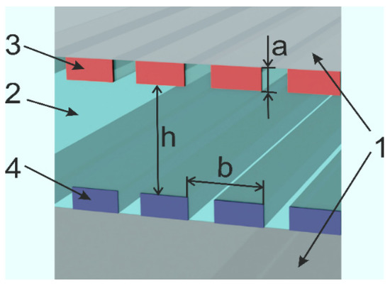
Figure 1.
Scheme of the structure under study. 1 (gray)—air, 2 (green)—substrate material, 3 and 4 (red and blue, the same for passive structures, and red correspond to inverting medium, blue corresponds to dissipative medium for PT-symmetry)—two subwavelength gratings with element height a and period b, distance between diffraction structures—h.
Optical radiation has TM-polarization, and falls on the indicated structure from above. Optical coupling is provided by the mechanisms of diffraction, reflection, and waveguide modes propagating along periodic structures.
For all cases, we numerically study the optical response of such a structure for resonant transmission and reflection using the finite elements method (FEM) for solving Maxwell equations.
In FEM simulations, the mesh accuracy was set at approximately “λ/50”, and there were no changes in simulation results caused by increasing the number of mesh cells. The mesh type was “triangle”. The “Boundary conditions” were set as “Periodic” in the horizontal direction, and as the “Perfectly matched layer (PML)” in the vertical direction. The structure’s parameters were optimized to obtain the minimum full width at half maximum (FWHM) of the resonant peak.
Since the main task is to study the structure in PT-symmetry mode, the geometry of the structure was optimized for the efficient hybridization of modes for the PT-symmetry case, leading to a resonant response in the transmission (reflection) spectra in the green region (Figure 2). This spectral range is of significant interest for various peaceful applications such as meteorite and comet research [36,37,38], medicine [39,40], etc. [41,42,43]. It should be noted that the optimization possibilities are complicated by the real materials’ dispersion response and absorption. As a result, although tuning the geometry of the studied structure allows for obtaining a resonant response at almost any given wavelength, the achievable resonance line parameters (e.g., spectral width) may differ significantly (by orders of magnitude) for different wavelengths. Therefore, when simply scaling the presented structure for other wavelengths, suboptimal operating modes of subwavelength periodic structures can be obtained. For the considered structure in the green wavelength range, two possible resonance lines were identified at 514.86 nm and 518.5 nm, corresponding to distances between the gratings of 607.5 and 630.1 nm (Figure 2).
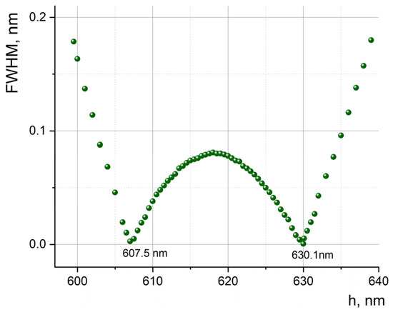
Figure 2.
The dependence of the resonance wavelength’s half-width of transmittance for the considered structure on the distance between sub-wavelength diffraction gratings.
The optimized structure has a height of structured layers that was set to 60 nm, with a grating period of 320 nm, a grating filling factor of 0.6, and a layer height between the structured layers of 607.5 and 630.1 nm.
The resonant response for the passive structure in the transparency region is shown in Figure 3. In this model case, the resonant transmission is 100% for both the optimized wavelength (514.86 nm and 518.5 nm) and the resonance width (approximately 0.063, 0.105 nm). The response of a structure with a geometry set for a resonant response in a wide range with visible radiation is shown in Figure 4.
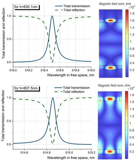
Figure 3.
Top line: resonance transmission and resonance reflection (left), symmetric field distribution for resonance at 518.5 nm (distance between waveguide gratings is 630.1 nm). Bottom line: resonance transmission and resonance reflection, symmetric field distribution for resonance at 514.86 nm (distance between waveguide gratings is 607.5 nm) (right).
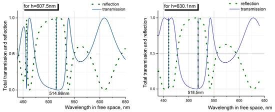
Figure 4.
Resonance response of the structure under consideration in the visible wavelength range. Blue line corresponds to resonance transmittance, and green line shows resonance reflection. (Left) for 518.5 nm (distance between waveguide gratings is 630.1 nm), (right) for 514.86 nm (distance between waveguide gratings is 607.5 nm).
From the figures, for the passive structure, we can see that isolated ultra-narrow resonances are observed at the same wavelengths over a wide range. In addition to resonances in the green region, resonances are observed at 460 nm (for a distance between structures of 630.1 nm) and 457 nm (for a distance between structures of 607.5 nm). The differences between resonances in the green and blue regions of the spectrum lie in the field localization. In the first case, the field is predominantly localized inside sub-wavelength gratings. In the second case, the field is uniformly distributed both inside the gratings and in the space between them (Figure 5). In the case of field localization in the sub-wavelength structural region, these structures act as waveguides, and for the green region of the spectrum, such structures can be used as optical switches of the field. This is due to the fact that when passing through a resonance point, field localization (phase shift between two waveguide modes) switches from one waveguide structure to another.
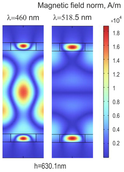
Figure 5.
(Left): field distribution for resonance at 460 nm (distance between waveguide gratings is 630.1 nm). (Right): field distribution for resonance at 518.5 nm (distance between waveguide gratings is 630.1 nm).
We also note that the efficiency of the resonant response also decreases when two periodic structures are shifted relative to each other, which will be discussed in the section “Active system with dispersion in the optical PT-symmetry mode”. Another mechanism for reducing the quality factor of the system is the finiteness of the size of the periodic structure and the deviation from the flat front of the incident radiation (Gaussian beam). The issues of the finiteness of size of the structure and the influence of Gaussian beam size effects are considered in detail in review [44], but it should be noted that if the size of the structure is larger than the size of the incident radiation cross-section and the spread of wave vector projections along the periodic structure corresponds to the spread of wave vectors in the Gaussian beam waist, then the decrease in the amplitude of transmission (reflection) of the electromagnetic radiation is at the scale of hundredths, and these edge effects can be neglected [45,46].
3. Optical System Responses
3.1. Passive System with Absorption
Initially, a numerical study of the structure under consideration was carried out without reference to specific materials. The imaginary part of the refractive index was set from ten-thousandths to hundredths of the real part, for a system with a response in the green wavelength range, while the real part of the refractive index was restored using the Kramers–Kronig transformation. This numerical calculation was motivated by the fact that in the visible region of the spectrum, silicon has an imaginary part of the refractive index comparable in magnitude to the real part, and at these wavelengths, it is hundredths of the real part of the refractive index. The numerical simulation showed (Figure 6) that the resonant transmission’s (reflection) profile is sensitive to the presence of absorption at ten-thousandths of the imaginary part of the refractive index, and it decreases in amplitude by 45% and broadens by an order of magnitude compared to the medium without absorption. For thousandths of the imaginary part of the refractive index, the width of the resonance curve increases to orders of a nanometer, while the amplitude decreases by 90–95%; with a further increase in the imaginary part of the refractive index, the transmission (reflection) line disappears completely. Thus, the use of the considered structures made of absorbing materials becomes impractical.
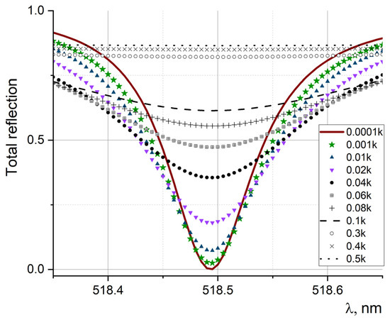
Figure 6.
The change in the resonant response in the presence of the imaginary part of the refractive index k, expressed in fractions of the real part.
The simulation performed using the full dispersion dependence with allowance for absorption in silicon in the visible region of the spectrum (from 450–600 nm, where the imaginary part of the refractive index is about hundredths of its real part) showed almost complete smearing of the resonant transmission line. Considering that the absorption length of silicon upon excitation in the region of 500 nm is 1 μm, and the thickness of the nanostructured silicon layer is less than 100 nm. Most of the incident light (∼90%) is transmitted down to the next layer, thus providing optical coupling between two subwavelength periodic structures, although in the passive mode (i.e., in the absence of an inverted medium), and it smears the resonant response.
3.2. Active System with Dispersion in the Optical PT-Symmetry Mode
Modeling the structure under consideration, provided that one of the subwavelength periodic structures has amplification, i.e., is in an inverted state, and the other has symmetrical losses, should, as expected, compensate for the disadvantages of the passive structure when absorption is considered. This configuration corresponds to optical PT-symmetry c involving symmetric index guiding and an antisymmetric gain/loss profile, that is, [33]. The coupled-mode equations describing this PT symmetric system are given by
where a and b—the waveguide modal amplitudes propagating along subwavelength periodic gratings, —a scaled propagation distance, k—the coupling coefficient, and , —the shifts in the propagation.
It should be noted that the structure under consideration has ultra-thin periodic gratings, which in turn form a periodically modulated Fabry–Perot resonator; in fact, the amplifying medium acts on the waveguide modes propagating along the periodic structure, and provides optical coupling. In the transverse direction, in which transmission resonances are fixed and reflected, its contribution is also made by the selective transmission (selection) of the resonator. In addition, as is known, the reflection from the amplifying layer can be greater than unity, so one of the gratings also directly affects the loss compensation, especially when considering multiple reflections inside the resonator formed by two subwavelength gratings. It should be noted that at the moment there are technological difficulties in creating an inverse population in silicon, but a promising direction for creating amplification in silicon is the use of nanopatterned Si [47,48,49,50].
We also carried out computer simulations and analytical analyses of the mechanism of coupling of waveguide modes, including considering saturation effects. The computer simulation of the optical response showed the possibility of obtaining ultranarrow resonances (having an FWHM of 0.00015 nm, i.e., an order of magnitude narrower than that of transmission (reflection) resonances in the model’s passive structure without considering absorption), while amplification up to 105 is observed (Figure 7).
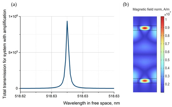
Figure 7.
Amplification of resonant transmittance of a PT-symmetry system (for the distance between waveguide gratings h = 630.1 nm) (a). Internal magnetic field distribution associated with the device (b).
It should be noted that in the simulation, the values of the refractive indices and other parameters of the materials of the structure were established according to the corresponding experimental studies [35]. However, it is obvious that with each new experiment, the values of the parameters of the materials used will not be completely identical. This usually greatly interferes with the successful practical implementation of parity time and anti-parity time systems. Indeed, in the manufacture of the structure described in the article, the values of the gain and loss levels (the imaginary part of the refractive index) in two parallel gratings may differ slightly from their specified values. In this case, the greatest influence on the response of the structure under study is exerted not directly by the deviation of the values of the gain and loss levels, but by their mismatch. In particular, in previous studies, we have shown that a mismatch of the loss and gain levels of gratings by more than 10% reduces the gain of the radiation passing through the system by about 520 times, and increases the spectral linewidth by about 120 times [31]. In this case, it is expected that in practice the mismatch between loss and gain levels will be several times smaller. In addition, the gain level can be controlled by changing the pump level of the system, which in practice should make it possible to reduce the mismatch value and approach the theoretically calculated characteristics.
In addition, let us clarify the question of the behavior of the system in the presence of a parallel shift of subwavelength structures relative to each other. Such a shift introduces a partial destruction of the optical coupling due to the phase difference that arises between the fields propagating along periodic subwavelength gratings, which leads to a shift and broadening of the resonant response. For a completely transparent model structure, the transmission maximum reaches unity and is observed for any shift within the period. However, in this case, the resonance shift occurs till 0.28 nm if both periodic subwavelength gratings are in opposite periods, and at resonance wavelength of incident light equal 518.78 nm, the width of such a resonance increases significantly compared to the transmission (reflection) resonance at the in-phase position of periodic subwavelength gratings, and quickly reaches about 0.1 nm (Figure 8).In fact, the system has a high sensitivity to violations of periodicity and to a shift in the resonance, and especially to the width of the resonance. Accounting for losses leads to even greater smearing of the resonance.
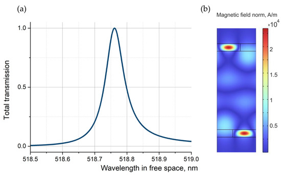
Figure 8.
Transmittance resonance for the model structure without considering the losses due to the shift of the gratings relative to each other (a). Internal magnetic field distribution associated with the device (b).
Considering losses and amplification (PT-symmetry case) leads to significantly larger changes in the resonance peak. Thus, at the maximum displacement of half a period, the resonance shift also occurs at 0.28 nm and corresponds to 518.9 nm. The amplitude of the resonance decreases by more than four orders of magnitude, while the width of such a resonance increases by 200 times compared to the transmission (reflection) resonance at in-phase positions of periodic sub-wavelength gratings (Figure 9). In fact, the system has high sensitivity to periodicity violations and resonance shifts, and especially to the width of the resonance. Figure 10 shows the dependencies of the center position’s shift on the FWHM of the resonance peak for passive and PT-symmetric structures.
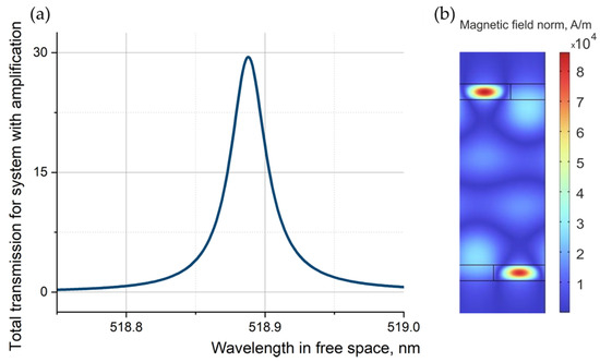
Figure 9.
Transmittance resonance for the model’s structure with a PT-symmetry configuration and with a shift of the gratings relative to each other (a). Internal magnetic field distribution associated with the device (b).
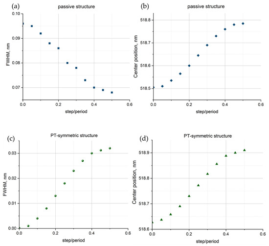
Figure 10.
Dependences of the width of the resonant peak and the position of its center following a lattice shift for passive (a,b) and PT-symmetric (c,d) structures. The shift value is given in fractions of the grating period.
4. Conclusions
Numerical investigations of a subwavelength double thin grating with optimized geometry used for monitoring resonant optical response in the visible optical band showed that these systems are very sensitive to the presence of absorption; in particular, at ten-thousandths of the imaginary part of the refractive index, it already decreases in amplitude by 45%, and broadens by an order of magnitude compared to the medium without absorption. The possibility of obtaining ultra-narrow reflection resonances (FWHM of 0.00015 nm) amplified up to 105 times when using PT-symmetry optical system subwavelength periodic structures is shown. Due to the properties of optical PT-symmetry, the proposed platform may be promising for use in the development of optical filters, including tunable ones, amplifiers, optomechanical and other types of sensors, etc. Compensation for losses and amplification in such a system are possible even when the imaginary part of the refractive index of the active grating does not exceed in magnitude that of a lossy symmetric grating. The sensitivity of the system’s response to the relative position of its two subwavelength gratings and the magnitude of the amplification coefficient of the active part can be used to tune the spectral characteristics of filters based on it, modulate the optical radiation incident on it, and create optomechanical sensors such as strain gauges.
Author Contributions
Conceptualization, methodology, resources E.A.E. and V.Y.V.; investigation and formal analysis I.R.K., A.A.Z. and E.V.S.; software, investigation and data curation V.I.S., V.A.S. and D.V.M.; investigation and visualization U.V.P.; writing—original draft preparation E.A.E., E.V.S. and V.I.S.; formal analysis, supervision, project administration, and funding acquisition E.A.E. and V.Y.V.; writing—review and editing, validation V.Y.V. All authors have read and agreed to the published version of the manuscript.
Funding
This research was funded by the Russian Science Foundation and the St. Peterburg Science Foundation, project #22-22-20072, https://rscf.ru/project/22-22-20072/ (access date: 30 May 2022).
Institutional Review Board Statement
Not applicable.
Informed Consent Statement
Not applicable.
Data Availability Statement
We use https://refractiveindex.info/.
Acknowledgments
E.A.E., E.V.S. and A.A.Z appreciate the funding from the Russian Science Foundation and the St. Peterburg Science Foundation, project #22-22-20072, https://rscf.ru/project/22-22-20072/ (access date: 30 May 2022). (“Control of the optical response of layered nanophononics structures via external control electromagnetic fields”).
Conflicts of Interest
The authors declare no conflict of interest.
References
- Wood, R.W. On a remarkable case of uneven distribution of light in a diffraction grating spectrum. In The London, Edinburgh, and Dublin Philosophical Magazine and Journal of Science; Philosophical Magazine Series; Taylor & Francis: London, UK, 1902; Volume 4, pp. 396–402. [Google Scholar]
- Hessel, A.; Oliner, A.A. A new theory of Wood’s anomalies on optical gratings. Appl. Opt. 1965, 4, 1275–1297. [Google Scholar] [CrossRef]
- Rosenblatt, D.; Sharon, A.; Friesem, A.A. Resonant grating waveguide structures. IEEE J. Quantum Electron. 1997, 33, 2038–2059. [Google Scholar] [CrossRef]
- Tibuleac, S.; Magnusson, R. Reflection and transmission guided-mode resonance filters. J. Opt. Soc. Am. A 1997, 14, 1617–1626. [Google Scholar] [CrossRef]
- Marcuse, D. Theory of Dielectric Optical Waveguides; Elsevier Science: Amsterdam, The Netherlands, 1991; pp. 396–402. [Google Scholar]
- Wang, S.S.; Magnusson, R.; Bagby, J.S.; Moharam, M.G. Guided-mode resonances in planar dielectric-layer diffraction gratings. J. Opt. Soc. Am. A 1990, 7, 1470–1474. [Google Scholar] [CrossRef]
- Magnusson, R.; Wang, S.S. New principle for optical filters. Appl. Phys. Lett. 1992, 61, 1022–1024. [Google Scholar] [CrossRef]
- Wang, S.S.; Magnusson, R. Theory and applications of guided-mode resonance filters. Appl. Opt. 1993, 32, 2606–2613. [Google Scholar]
- Moharam, M.G.; Grann, E.B.; Pommet, D.A.; Gaylord, T.K. Formulation for stable and efficient implementation of the rigorous coupled-wave analysis of binary gratings. J. Opt. Soc. Am. A 1995, 12, 1068–1076. [Google Scholar] [CrossRef]
- Hermannsson, P.G.; Sorensen, K.T.; Vannahme, C.; Smith, C.L.C.; Klein, J.J.; Russew, M.-M.; Grutzner, G.; Kristensen, A. All-polvmer photonic crystal slab sensor. Opt. Express 2015, 23, 16529–16539. [Google Scholar] [CrossRef]
- Quaranta, G.; Basset, G.; Martin, O.J.F.; Gallinet, B. Recent Advances in Resonant Waveguide Gratings. Laser Photonics Rev. 2018, 12, 1800017. [Google Scholar]
- Halir, R.; Bock, P.J.; Cheben, P.; Ortega-Moñux, A.; Alonso-Ramos, C.; Schmid, J.H.; Lapointe, J.; Xu, D.-X.; Wangüemert-Pérez, J.G.; Molina-Fernández, Í.; et al. Waveguide sub-wavelength structures: A review of principles and applications. Laser Photonics Rev. 2015, 9, 25–49. [Google Scholar]
- Divya, J.; Selvendran, S.; Sivanantha, R.A.; Sivasubramanian, A. Surface plasmon based plasmonic sensors: A review on their past, present and future. Biosens. Bioelectron. X 2022, 11, 100175. [Google Scholar] [CrossRef]
- Pathak, A.K.; Rahman, B.M.A.; Viphavakit, C. Nanowire Embedded Micro-Drilled Dual-Channel Approach to Develop Highly Sensitive Biosensor. IEEE Photonics Technol. Lett. 2022, 34, 707–710. [Google Scholar] [CrossRef]
- Duan, Q.; Liu, Y.; Chang, S.; Chen, H.; Chen, J.-h. Surface Plasmonic Sensors: Sensing Mechanism and Recent Applications. Sensors 2021, 21, 5262. [Google Scholar] [CrossRef] [PubMed]
- Xuan, Z.; Junyu, L.; Qingquan, L.; Fei, Y.; Wang, S.; Wei, L. Artificial structural colors and applications. Innovation 2021, 2, 100081. [Google Scholar]
- Ge, F.; Xiao, H.; Jialiang, X. Strongly coupled systems for nonlinear optics. Laser Photonics Rev. 2021, 15, 2000514. [Google Scholar]
- Raghunathan, V.; Deka, J.; Menon, S.; Biswas, R.; A.S, L.K. Nonlinear Optics in Dielectric Guided-Mode Resonant Structures and Resonant Metasurfaces. Micromachines 2020, 11, 449. [Google Scholar] [CrossRef]
- Overvig, A.C.; Stephanie, C.M.; Nanfang, Y. Multifunctional nonlocal metasurfaces. Phys. Rev. Lett. 2020, 125, 017402. [Google Scholar]
- Hu, Y.; Xiong, Y. High-Q and tunable analog of electromagnetically induced transparency in terahertz all-dielectric metamaterial. Appl. Opt. 2022, 61, 1500–1506. [Google Scholar] [CrossRef]
- Brunetti, G.; Marocco, G.; Benedetto, A.; Giorgio, A.; Armenise, M.N.; Ciminelli, C. Design of a large bandwitdth 2 × 2 interferometric switching cell based on sub-wavelength grating. J. Opt. 2021, 23, 085801. [Google Scholar]
- Kazanskiy, N.L.; Butt, M.A.; Khonina, S.N. Silicon photonic devices realized on refractive index engineered subwavelength grating waveguides-A review. Opt. Laser Technol. 2021, 138, 106863. [Google Scholar] [CrossRef]
- Letartre, X.; Mouette, J.; Leclercq, J.; Romeo, P.R.; Seassal, C.; Viktorovitch, P. Switching Devices With Spatial and Spectral Resolution Combining Photonic Crystal and MOEMS Structures. J. Light. Technol. 2003, 21, 1691–1699. [Google Scholar] [CrossRef]
- Wang, Z.; Zhang, B.; Deng, H. Dispersion Engineering for Vertical Microcavities Using Subwavelength Gratings. Phys. Rev. Lett. 2015, 114, 073601. [Google Scholar] [PubMed]
- Karagodsky, V.; Sedgwick, F.G.; Chang-Hasnain, C.J. Theoretical analysis of subwavelength high contrast grating reflectors. Opt. Express 2010, 18, 16973–16988. [Google Scholar]
- Lee, H.-S.; Yoon, Y.-T.; Lee, S.-S.; Kim, S.-H.; Lee, K.-D. Color filter based on a subwavelength patterned metal grating. Opt. Express 2007, 15, 15457–15463. [Google Scholar] [CrossRef]
- Yeh, P. A new optical model for wire grid polarizers. Opt. Commun. 1978, 26, 289–292. [Google Scholar] [CrossRef]
- Grann, E.B.; Moharam, M.G.; Pommet, D.A. Artificial uniaxial and biaxial dielectrics with use of two-dimensional subwavelength binary gratings. J. Opt. Soc. Am. A 1994, 11, 2695–2703. [Google Scholar] [CrossRef]
- Chen, Y.-T.; Lee, Y.-C.; Lai, Y.-H.; Lim, J.-C.; Huang, N.-T.; Lin, C.-T.; Huang, J.-J. Review of integrated optical biosensors for point-of-care applications. Biosensors 2020, 10, 209. [Google Scholar] [CrossRef]
- Han, Y.; Yang, J.; He, X.; Huang, J.; Zhang, J.; Chen, D.; Zhang, Z. High quality factor electromagnetically induced transparency-like effect in coupled guided-mode resonant systems. Opt. Express 2019, 27, 7712–7718. [Google Scholar]
- Efremova, E.A.; Krylov, I.R.; Prokhorova, U.V.; Shalymov, E.V.; Shoev, V.I.; Venediktov, V.Y.; Zinchik, A.A. Spectral characteristics of coupled gratings at PT-symmetry and its destruction. In Advanced Sensor Systems and Applications; SPIE: Bellingham, WA, USA, 2022; Volume 12321. [Google Scholar]
- El-Ganainy, R.; Makris, K.G.; Christodoulides, D.N.; Musslimani, Z.H. Theory of coupled optical PT-symmetric structures. Opt. Lett. 2007, 32, 2632–2634. [Google Scholar] [CrossRef]
- Zyablovsky, A.A.; Vinogradov, A.P.; Pukhov, A.A.; Dorofeenko, A.V.; Lisyanskym, A.A. PT-symmetry in optics. Phys.-Uspekhi 2014, 57, 1063. [Google Scholar] [CrossRef]
- Ramy, E.; Makris, G.K.; Khajavikhan, M.; Ziad, M.; Rotter, S.; Christodoulides, D. Non-Hermitian physics and PT symmetry. Nat. Phys. 2018, 14, 11–19. [Google Scholar]
- Schinke, C.; Peest, P.C.; Schmidt, J.; Brendel, R.; Bothe, K.; Vogt, M.R. Uncertainty analysis for the coefficient of band-to-band absorption of crystalline silicon. Aip Adv. 2015, 5, 067168. [Google Scholar]
- Taylor, M.J.; Gardner, L.C.; Murray, I.S. Jet-Like Structures and Wake in Mg I (518 nm) Images of 1999 Leonid Storm Meteors. Earth Moon Planets 1998, 182, 379–389. [Google Scholar] [CrossRef]
- Abe, S. Meteoroids and Meteors—Observations and Connection to Parent Bodies. In Small Bodies in Planetary Systems; Springer: Berlin/Heidelberg, Germany, 2009; pp. 129–166. [Google Scholar]
- Lin, H.; Lee, C.-H.; Gerdes, D.; Adams, F.; Becker, J.; Napier, K.; Markwardt, L. Detection of Diatomic Carbon in 2I/Borisov. Astrophys. J. 2020, 889, 30. [Google Scholar]
- Hatice, T.A.; Betül, S.U.; Fakhriddin, S.; Selma, U.; Nilüfer, Y.; Mehmet, C.Ö.; Sidre, E.; Atike, B.T.; Funda, D.-A.; Kamil, B. Rose Bengal-Mediated Photodynamic Antimicrobial Treatment of Acanthamoeba Keratitis. Curr. Eye Res. 2020, 45, 1205–1210. [Google Scholar]
- Smith, A.F.; Zhao, B.; You, M. Microfluidic DNA-based potassium nanosensors for improved dialysis treatment. BioMed. Eng. Online 2019, 18, 73. [Google Scholar]
- Chase, A.P.; Boss, E.S.; Haëntjens, N.; Culhane, E.; Roesler, C.; Karp-Boss, L. Plankton Imagery Data Inform Satellite-Based Estimates of Diatom Carbon. Geophys. Res. Lett. 2022, 49, 13. [Google Scholar] [CrossRef]
- Kaufmann, F.; Forster, C.; Hummel, M.; Olowinsky, A.; Beckmann, F.; Moosmann, J.; Roth, S.; Schmidt, M. Characterization of Vapor Capillary Geometry in Laser Beam Welding of Copper with 515 nm and 1030 nm Laser Beam Sources by Means of In Situ Synchrotron X-ray Imaging. Metals 2023, 13, 135. [Google Scholar] [CrossRef]
- Hornung, M.; Becker, G.A.; Seidel, A.; Reislöhner, J.; Liebetrau, H.; Bock, L.; Keppler, S.; Kessler, A.; Zepf, M.; Hein, J.; et al. Generation of 25-TW Femtosecond Laser Pulses at 515 nm with Extremely High Temporal Contrast. Appl. Sci. 2015, 5, 1970–1979. [Google Scholar] [CrossRef]
- Boye, R.R.; Raymond, K.K. Investigation of the effect of finite grating size on the performance of guided-mode resonance filters. Appl. Opt. 2000, 39, 3649–3653. [Google Scholar] [CrossRef]
- Gambino, F.; Giaquinto, M.; Ricciardi, A.; Cusano, A. A review on dielectric resonant gratings: Mitigation of finite size and Gaussian beam size effects. Results Opt. 2022, 6, 100210. [Google Scholar]
- Efremova, E.A.; Perminov, S.V.; Vergeles, S.S. Resonance behavior of diffraction on encapsulated guided-mode grating of subwavelength thickness. Photonics Nanostruct. -Fundam. Appl. 2021, 46, 100953. [Google Scholar] [CrossRef]
- Trupke, T.; Green, M.A.; WЁurfel, P. Optical gain in materials with indirect transitions. J. Appl. Phys. 2003, 93, 9058–9061. [Google Scholar] [CrossRef]
- Pavesi, L.; Dal, N.L.; Mazzoleni, C.; Franzo, G.; Priolo, F. Optical gain in silicon nanocrystals. Nature 2000, 408, 440–444. [Google Scholar] [CrossRef] [PubMed]
- Cloutier, S.; Kossyrev, P.; Xu, J. Optical gain and stimulated emission in periodic nanopatterned crystalline silicon. Nat. Mater. 2005, 4, 887–891. [Google Scholar] [CrossRef]
- Pavesi, L. Silicon-Based Light Sources for Silicon Integrated Circuits. Adv. Opt. Technol. 2008, 2008, 416926. [Google Scholar] [CrossRef]


Disclaimer/Publisher’s Note: The statements, opinions and data contained in all publications are solely those of the individual author(s) and contributor(s) and not of MDPI and/or the editor(s). MDPI and/or the editor(s) disclaim responsibility for any injury to people or property resulting from any ideas, methods, instructions or products referred to in the content. |
© 2023 by the authors. Licensee MDPI, Basel, Switzerland. This article is an open access article distributed under the terms and conditions of the Creative Commons Attribution (CC BY) license (https://creativecommons.org/licenses/by/4.0/).