Communication

Regenerative Shaper of Ultrashort Light Pulses

by
Kęstutis Regelskis
*,
Gustas Liaugminas
and
Julijanas Želudevičius
Department of Laser Technology, Center for Physical Sciences & Technology, Savanoriu Ave. 231, LT-02300 Vilnius, Lithuania
*
Author to whom correspondence should be addressed.
Photonics 2023, 10(7), 836; https://doi.org/10.3390/photonics10070836
Submission received: 3 June 2023 / Revised: 13 July 2023 / Accepted: 17 July 2023 / Published: 20 July 2023

Abstract

:
In this article, we propose and demonstrate an ultrashort light pulse regenerative shaper based on a closed-loop double-stage Mamyshev regenerator with an electrically controllable acousto-optic switch. This setup allowed us to apply an initial pulse from an external pulse source and to reshape the pulse to an ultrashort, high-quality, compressible one, the parameters of which were determined by the parameters of the regenerative circuit (RC), due to repeated pulse round-trips in the closed-loop RC. It was found that after 3–7 round-trips the energy of the regenerated pulse was almost independent of the energy of the initial pulse. However, at least 20 round-trips in the RC were required to shape the steady repetitive pulse. In addition, we demonstrated, both experientially and numerically, that the generation of periodic pulse sequences with limited pump power can lead to a rearrangement of the pulse sequences, which results in variations in the length of the pulse sequence from period to period.

1. Introduction

Operation of most ultrashort pulse-laser sources is based on mode-locking. Standard mode-locked laser sources operate at a fixed repetition rate determined by their cavity length and are not freely controllable [1,2,3]. However, in some applications it is desirable to produce pulse trains of arbitrary repetition rate or to generate pulse on demand. For example, in two-photon microscopy, to increase the imaging depth of the biological sample, the repetition rate of the excitation pulses has to be adjusted with respect to their energy to avoid overheating of the sample [4]. The optimal repetition rate depends on the imaging depth, so a tunable repetition rate source has to be used to ensure optimal operation at different penetration depths [5]. Similarly, in laser processing of materials using polygon scanners, the laser-light source needs to operate at a variable repetition rate in order to create arbitrarily arranged structures [6].
An alternative to mode-locked laser sources can be gain-switched laser diodes. They can be electronically triggered to produce arbitrary repetition rates or more complicated pulse trains. But the generated pulses have much greater inter-pulse amplitude and phase noise, they are much longer (10–100 ps) than pulses generated by mode-locked lasers, and usually cannot be directly compressed to the transform limit [7,8,9,10,11].
Recently, Fu et al. [11] demonstrated that one of the ways to improve the characteristics of the light pulses generated by a gain-switched laser diode is to reshape the light pulses using a Mamyshev regenerator [12]. Inside the Mamyshev regenerator, the initially noisy pulses from the gain-switched laser diode were spectrally broadened and filtered by a band-pass filter. As a result, after amplification using parabolic pre-shaping and dechirping, nearly transform-limited pulses of 140 fs duration with 13 MW peak power were obtained. Thus, the regenerator shortened the pulses and improved their coherence [11,13]. A single-stage Mamyshev regenerator cleans the initial pulses from noise and distortions quite well, but the parameters of the output pulses (i.e., energy and spectral and temporal characteristics) are sensitive to the parameters of the initial pulses. For example, the energy of the output pulses depends significantly on the energy of the initial pulses. This drawback can be eliminated by repeatedly regenerating the pulse in several Mamyshev regenerators connected in series. In this way, pulse regeneration results in a pulse of very well-defined parameters, regardless of the initial pulse. However, the realization of this method is quite complex and expensive because it requires a large number of regenerators and each regenerator must have an amplifier to compensate for the spectral filtering losses [14].
We trialed the use of a regenerative shaper of ultrashort light pulses using a closed-loop double-stage Mamyshev regenerator with electrically controllable acousto-optic switch. This setup allowed us to set any desired number of pulse regeneration cycles in the same regenerative circuit (RC) and made it possible to shape an eigenpulse, whose parameters were strictly determined by the RC parameters, from any initial pulse. The energy and duration of the shaped pulse were always the same regardless of the energy and duration of the initial pulse. It should be noted that closed-loop double-stage Mamyshev regenerators with unlimited number of pulse regeneration cycles are well known as Mamyshev oscillators or generators. They are able to generate continuously high-quality ultrashort light pulses with a fixed pulse repetition rate [15,16,17,18,19,20]. Mamyshev oscillators have a high potential for generating high-energy and ultrashort light pulses, making them ideal for industrial applications and physical research. Recently, Repgen et al. [21] demonstrated a Mamyshev oscillator that generated pulses with a repetition rate of 11 MHz and a pulse energy of 31 nJ. Moreover, these pulses were spectrally filtered and amplified in a single-stage Yb-doped fiber up to 1 μJ pulse energy. After temporal dechirping of amplified pulses, autocorrelation duration below 50 fs was achieved [21].

2. Experimental Setup and Numerical Simulations

A schematic diagram of our experimental setup is depicted in Figure 1. The key components of the ultrashort pulse regenerative shaper were: Yb-doped polarization-maintaining (PM) single-mode (SM) fiber (YDF), PM SM passive fibers (PF1, PF2), band reflective filters (F1, F2), and an electrically controllable four-port acousto-optic switch (AOS). The length of the Yb-doped fiber was set to 1.2 m (Coherent PM-YSF-HI-HP; an estimated Yb ion concentration ~3 × 1025 1/m3), the lengths of PF1 and PF2 were chosen so that the AOS was in the center of the RC (in this article, we refer to the RC as a part of the regenerative shaper in which the pulse is regenerated, i.e., filters F1 and F2 and all other elements placed between them (fibers, amplifier, etc.)). The overall fiber length (including all passive and gain fibers) was set to ~11.4 m, which corresponded to a ~9 MHz pulse repetition rate (round-trip time ~111 ns). Two reflective diffraction gratings in combination with gradient-index (GRIN) lens collimators were used as band reflective filters F1 and F2, with center wavelengths λ_F1 = 1034.9 nm and λ_F2 = 1028.6 nm and a spectral bandwidth of 3 nm (FWHM) for both of the filters. The reflection spectrum of the each of the filters has a nearly Gaussian shape (see Figure 1 top-right inset). The Yb-doped fiber was continuously pumped through a signal-pump multiplexer (WDM) with an SM laser diode (LD), generating at the 976 nm wavelength.
The AOS was assembled in our laboratory using a free-space acousto-optic modulator (Gooch & Housego 3200-1113; operating frequency 200 MHz) and four PM fibers with GRIN lens collimators. The rise/fall time of the assembled AOS was 20 ns and 28 ns, respectively. This switching speed was sufficient to lock the injected initial pulse into the RC before it returned after reflection from filter F1. The measured light transmission between different ports of the AOS in the “on” and “off” states was as follows: between ports 1 and 2, transmission was 11% and 75%; between ports 1 and 4 ports, transmission was 54% and 0.03%; between ports 2 and 3, transmission was 55% and 0.03%; and between ports 3 and 4 ports, transmission was 11% and 68%. Port 1 was used to inject the initial pulse into the RC, port 2 and port 3 were used to connect the RC, and port 4 was used to extract the shaped pulse from the RC. To control the AOS, an electrical pulse/delay generator (Berkeley Nucleonics Corporation BNC 575) was used. This electrical pulse generator was triggered by the initial pulse and was able to produce electrical pulses with a variable delay and pulse width. When the initial pulse was injected to the RC, the AOS was in the “off” state and initial pulse traveled from port 1 to port 2 and entered the RC. While the initial pulse traveled to the F1 and bounced back, the AOS turned to the “on” state, and the pulse then traveled between ports 2 and 3 and remained locked inside the RC. After a certain number of round-trips, when the pulse was finally shaped, the AOS turned back to the “off” state and the shaped pulse was sent through port 3 to output port 4. Since 11% of the pulse energy from port 3 entered output port 4 in the “on” state, the pulse-shaping process could be observed after each round-trip through the RC. At the output, a pulse picker (PP) was used to select individual pulses from the pulse sequence. Operation of the RC is based on self-phase modulation (SPM) in a fiber and offset spectral filtering [15]. Because spectral broadening of the pulse depends on the peak power, the RC operates as a nonlinear optical gate, transmitting only pulses with high enough peak power.
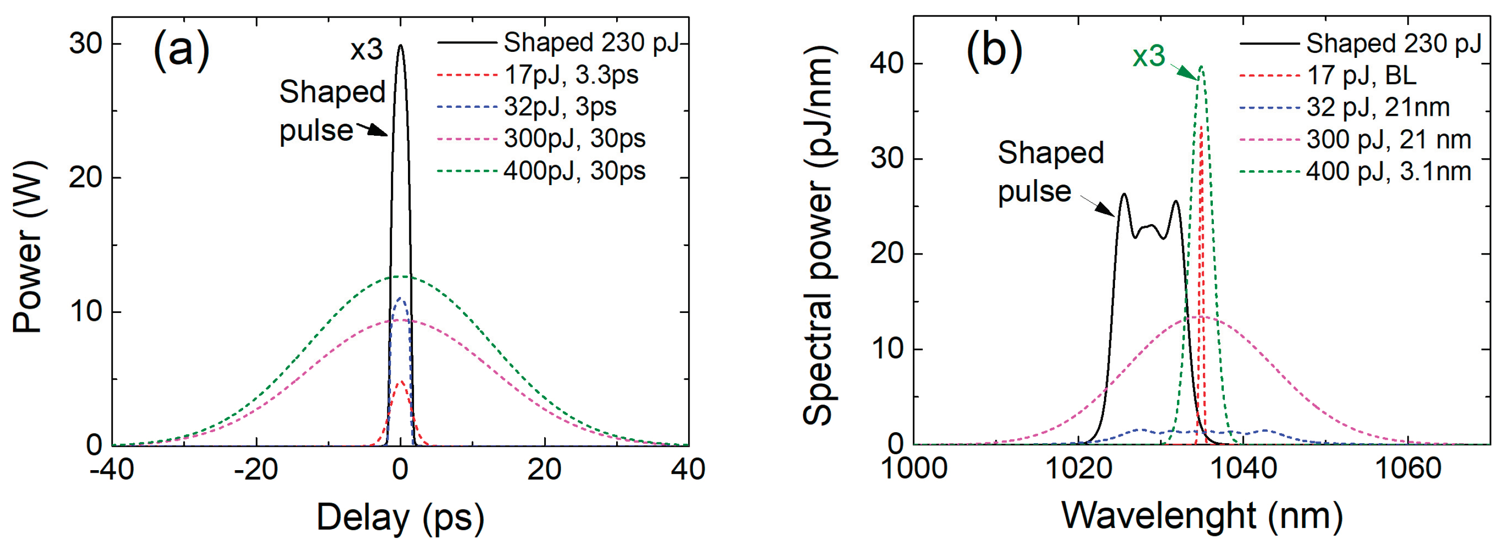
Before starting our experimental investigations, we performed numerical simulations of the ultrashort pulse regenerative shaper. Pulse propagation in the RC requires a description of three main effects: pulse propagation in a passive (active) fiber, pulse amplification, and pulse spectral filtering. Pulse propagation in a passive optical fiber, including SPM and group velocity dispersion up to the third order, was modeled using a numerical integration of the nonlinear Schrödinger equation by the split-step Fourier method [22]. The Yb-doped fiber used as a gain medium was approximated by an optical-frequency-dependent point amplifier [23]. Spectral filtering of the pulse was modeled in a frequency domain by multiplying the pulse spectrum with the reflection function of the filter. The RC parameters were set accordingly to the experimental setup and modeled using initial pulses with various parameters (energy, duration, spectral width). Modeling results showed that the parameters of the shaped pulse were independent of the initial pulse parameters. The energy and duration of the initial pulse could differ tens of times in comparison to the energy and duration of the shaped pulse (Figure 2a) (shaped-pulse duration 2.7 ps at FWHM), especially when the spectrum of the initial pulse matched well the reflection band of the filter F1 (Figure 2b). This feature potentially can be useful for regenerative shaping of the gain-switched diode-generated pulses.
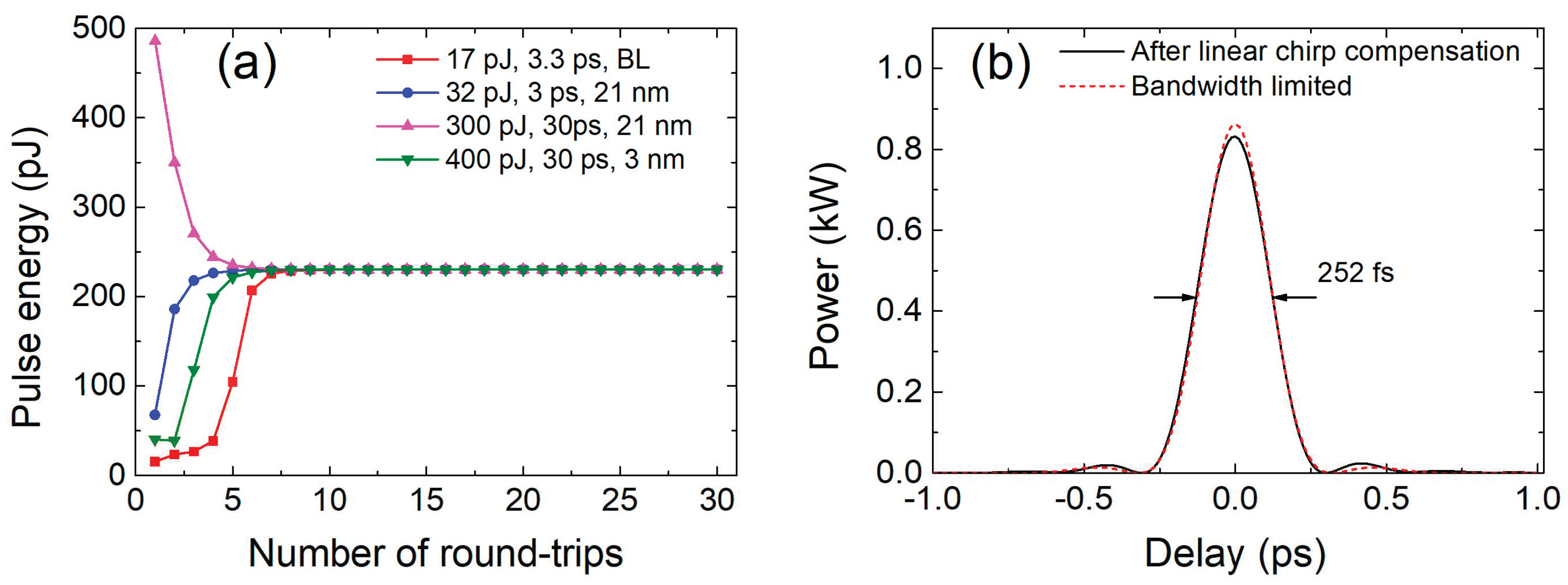
The simulation results showed that the energy of the 3.3 ps bandwidth-limited initial pulse needed to be at least 17 pJ to shape the eigenpulse. At lower energies, the pulse simply disappeared. If the spectrum of the initial pulse was wider than the reflectance bandwidth of filter F1, the energy of the initial pulse needed to be correspondingly higher. Also, the longer the initial pulse, the more energy was required to excite and shape the eigenpulse. The energy of the initial Gaussian pulse of 30 ps needed to be at least 300 pJ. In addition, if the 30 ps initial pulse had a broad spectrum and was chirped, then spectral filtering (with filter F1) shortened the pulse, making it easier to excite and shape the eigenpulse (see Figure 2a,b magenta curves). Figure 3a shows the energy of the regenerated pulses as a function of the number of round-trips in the RC for initial pulses of different energies, whose temporal profiles and spectra are shown in Figure 2.
As can be seen in Figure 3a, after four to seven round-trips in the RC, a pulse was already shaped and its energy was almost independent of the energy of the initial pulse. This property can be used to produce identical pulses from completely different initial pulses. The shaped pulse was linearly chirped and could be compressed close to bandwidth-limited duration as short as 252 fs by compensating only second-order dispersion (Figure 3b). For the numerical simulations, a single-pass gain in the YDF of 19 times was used to match the experimental conditions. Simulations showed that at a single pass gain threshold (15.5 times) the energy of the shaped pulse was about 170 pJ. At lower gain, the pulse disappeared. The upper gain level was limited by the generation of continuous wave or by lasing where the spectra of the filters overlapped. Numerical modeling also revealed that multiple pulses could be shaped from a distorted or modulated initial pulse (Figure 4). Each local peak of the initial pulse could be interpreted as a separate initial pulse. By applying such an initial pulse with a modulated envelope into the RC, it was possible to shape two or more individual pulses simultaneously. It was found that if the modulation period of the initial pulse or the distance between adjacent peaks was less than the duration of the pulse to be shaped, then a single pulse would be shaped (Figure 4a). And if the period of the modulations or the distance between adjacent peaks was greater than the duration of the shaped pulse, then multiple pulses could be excited simultaneously (Figure 4b). Thus, several pulses could be shaped simultaneously in the RC. The number of excited pulses also depended on the energy of the initial pulse and the height of the peaks. The higher the peak, the easier it was to excite the pulse. The number of excited pulses was also able to be affected by the spectrum shape of the initial pulse. As the initial pulse propagated toward the filter F1, dispersion and SPM in the fiber could result in the development of several peaks in the pulse temporal envelope.

3. Experiment Results and Discussion

3.1. Regenerative Shaping at a Fixed Round-Trip Number

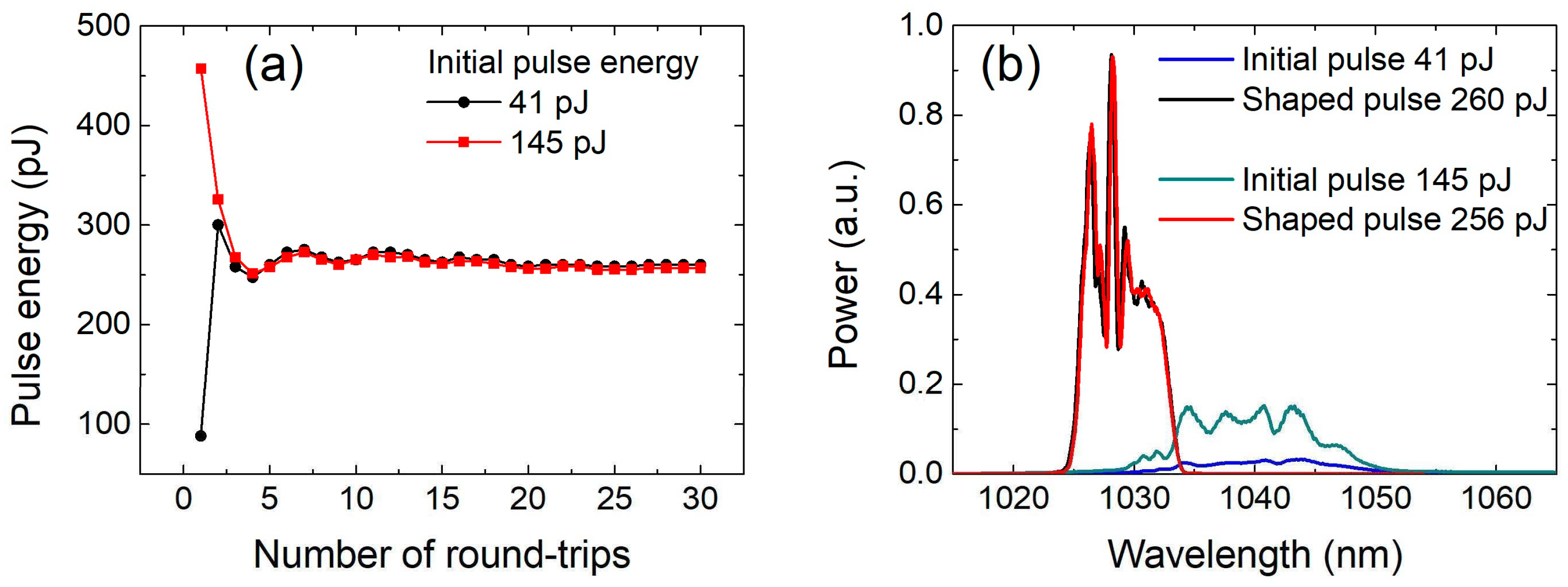
Since we did not have a suitable pulsed diode laser, we used a picosecond pulse fiber laser as the initial pulse source to study the characteristics of the regenerative shaper. The fiber laser generated ~3.3 ps (FWHM) pulses (see the autocorrelation function in Figure 5a) at a central wavelength of ~1040 nm with a spectral bandwidth of 14 nm (FWHM) (Figure 6b). The pulse repetition rate of the fiber laser was 10 kHz. Initial pulses were injected through port 1 into the RC and then, after tuning synchronization between initial pulses and AOS switching times, the pulse sequences were excited (Figure 5b). The time interval between adjacent pulses in the sequence was 111 ns and corresponded to the round-trip time of the pulse in the RC. The last high-amplitude pulse seen in the oscillogram is the shaped pulse extracted from the RC when the AOS switched to the “off” state. The duration of the shaped pulse was estimated to be ~2.3 ps (FWHM) (see the autocorrelation function in Figure 5c).
The preceding low-amplitude pulses are visible because the transmission of the AOS between ports 3 and 4 remained at 11% in the “on” state while the pulse was being shaped. Despite this being a drawback in general, in our investigation it is very useful for observing the evolution of pulse shaping on the oscilloscope screen. In order to measure the average power or energy of each individual pulse (including the last-shaped pulse) in the sequence, it was necessary to use a PP at output port 4. The results of these measurements at different initial pulse energy are shown in Figure 6a. The measurements were carried out by setting 30 round-trips inside the RC. After 30 round-trips, the pulse was completely shaped and its energy (Figure 6a) or spectral shape (Figure 6b) was almost independent of the energy of the initial pulse. From Figure 6a it can be seen that the energy of the regenerated pulse was almost independent of the energy of the initial pulse after 3–5 round-trips. Initially, the energy of the pulse oscillated with increasing number of round-trips. However, the amplitude of the oscillations decreased with the subsequent round-trips, and the energy of the regenerated pulse became stable after more than 20 round-trips. These oscillations in energy were not predicted by the numerical simulations. This could have been due to inaccuracies in the numerical model, or it could be a specific feature of the experimental setup. The lowest energy of the initial pulse required to start the regenerative pulse shaper was ~35 pJ.
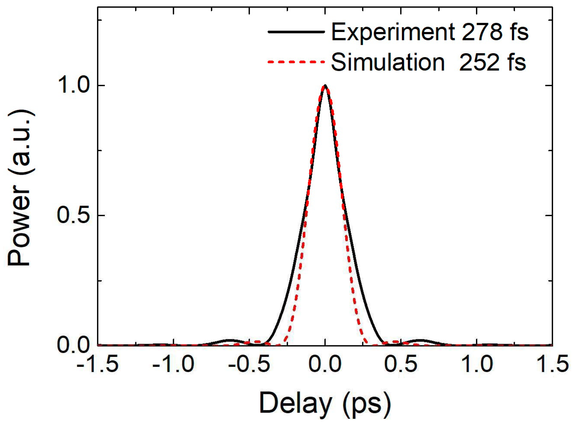
The spectrum of the shaped pulse presented in Figure 6b (red or black trace) corresponded to a bandwidth-limited pulse duration of 278 fs (Figure 7 continuous black trace). The duration of the experimental bandwidth-limited pulse was slightly longer than the numerically modelled one (Figure 7, dashed red trace). The reason for this was the sufficiently pronounced modulation in the spectrum of the shaped pulse.
It was observed that the pump power interval of the regenerative shaper operation was rather limited. If the pump power was too low, there was not enough energy stored in the YDF for the pulse to make enough round-trips inside the RC to finally shape the pulse. The lowest pump power was ~90 mW (at 30 round-trips) and the energy of the shaped pulse was ~210 pJ (theoretically 170 pJ). If the pump power was too high, pulsations and parasitic lasing began in the RC. The strong lasing peak appeared where the reflectance spectra of the filters F1 and F2 overlap.

3.2. Generation of Periodic Pulse Sequences with Limited Pump Power

It was also found that setting a higher number of pulse round-trips required a proportional increase in the pump power. After setting the number of round-trips to 250, we measured the energy of the individual pulses after each round-trip until regeneration finally stopped (Figure 8). The energy of the initial pulses was set to ~95 pJ. The pump power was 107 mW. Results showed that that pulse becomes stable after 20 round-trips and its energy stayed almost constant for up to 143 round-trips. During the following round-trips, the energy of the regenerated pulse began to drop rapidly until regeneration stopped after 159 round-trips (Figure 8 black curve). This limit could be extended if the pump power was increased. Increasing the pump power to 112 mW allowed the pulse to complete up to 180 round-trips before it started to decay.
Similar experiments were carried out after setting a maximum possible number of ~900 pulse round-trips in the RC. The repetition rate of the initial pulse was 10 kHz (period 100 µs), as in the preceding measurements. The pulse round-trip time in the RC was ~111 ns. Thus, the pulse could make a maximum of 100 μs/111 ns = 901 round-trips in the RC during one period. The peculiarities of the pulse shaping in the RC were monitored with an oscilloscope.
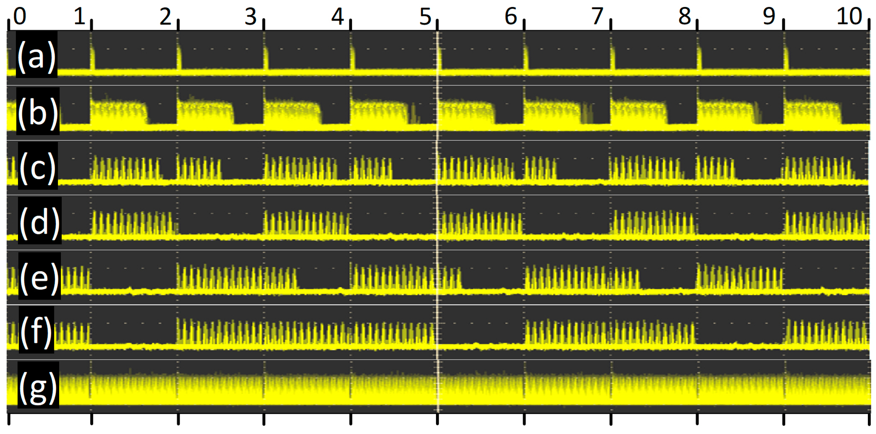
We started from the minimum pump power when pulse regeneration appeared and by further increasing the pump power, we observed the changes in the oscillogram (Figure 9). One division of the oscillogram scale corresponded to 100 µs (equal to the period between the initial pulses), and the width of the entire oscillogram corresponded to 1000 µs or 10 divisions. Below, each oscillogram is described separately in alphabetical order, indicating the pump power.
(Figure 9a)—86 mW. The pump power threshold when pulses were sometimes excited from initial pulses and they made several round-trips in the RC is 81 mW. With further increase in the pump power up to 83 mW, pulses usually appeared in every period of initial pulse.
(Figure 9b)—132 mW. More than half of the period was filled with pulses.
(Figure 9c)—168 mW. With further increase in pump power, interesting phenomena began. Above 164 mW, less than half of one period was filled with pulses, and more than half of another period was filled with pulses. Alternatively, it could be that one period was only be half filled with pulses, while the next period was completely filled, with this one being followed by an empty period.
(Figure 9d)—173 mW. Pulses appeared only every second period. Most of the period was filled with pulses.
(Figure 9e)—175 mW. The pulses filled one period completely and part of the next period, followed by an empty interval. Sometimes two periods were filled with pulses at once and the period after them was empty. The regenerative shaper tended to regenerate pulses over longer periods with longer idle intervals than predefined.
(Figure 9f)—180 mW. In most cases, two or three periods were filled consecutively with pulses, followed by an empty period. Further increases in power resulted in more pulse-filled periods followed by one empty period.
(Figure 9g)—188 mW. Finally, all periods were filled with pulses. Further increasing the pump power did not change the oscillogram pattern; only the energy of the regenerated pulses increased. In the absence of initial pulses, the regenerative shaper did not start by itself, even at the maximum pump power.
In order to better understand the peculiarities of the shaping of the periodic pulse sequences (especially the oscillograms shown in Figure 9c–f), additional numerical simulations were carried out. The RC parameters were set according to the experimental setup. To speed up the calculations, an initial pulse was applied every hundredth round-trip in the RC. Thus the period duration was 100 round-trips (~900 round-trips were used in the experiment). The results of the numerical simulations (Figure 10) showed a similar behavior of the periodic pulse sequence shaping as in the experimentally recorded oscillograms. As long as the pump power did not exceed ~130 mW, the regenerated pulses disappeared before completing 50 round-trips (half period) in the RC (Figure 10a,b). In this case, pulse sequences of constant length were generated in each period. However, when the pump power exceeded ~130 mW, the periodic pulse sequences started to rearrange. In the following periods, the lengths of the pulse sequences became unequal (Figure 10c–e). And finally, when the pump power reached 164 mW, all the periods were completely filled with pulses (Figure 10f). In this case, the pulse regenerative shaper could generate a continuous sequence of pulses. By further increasing the pump power a continuous pulse sequence of higher energy was generated.
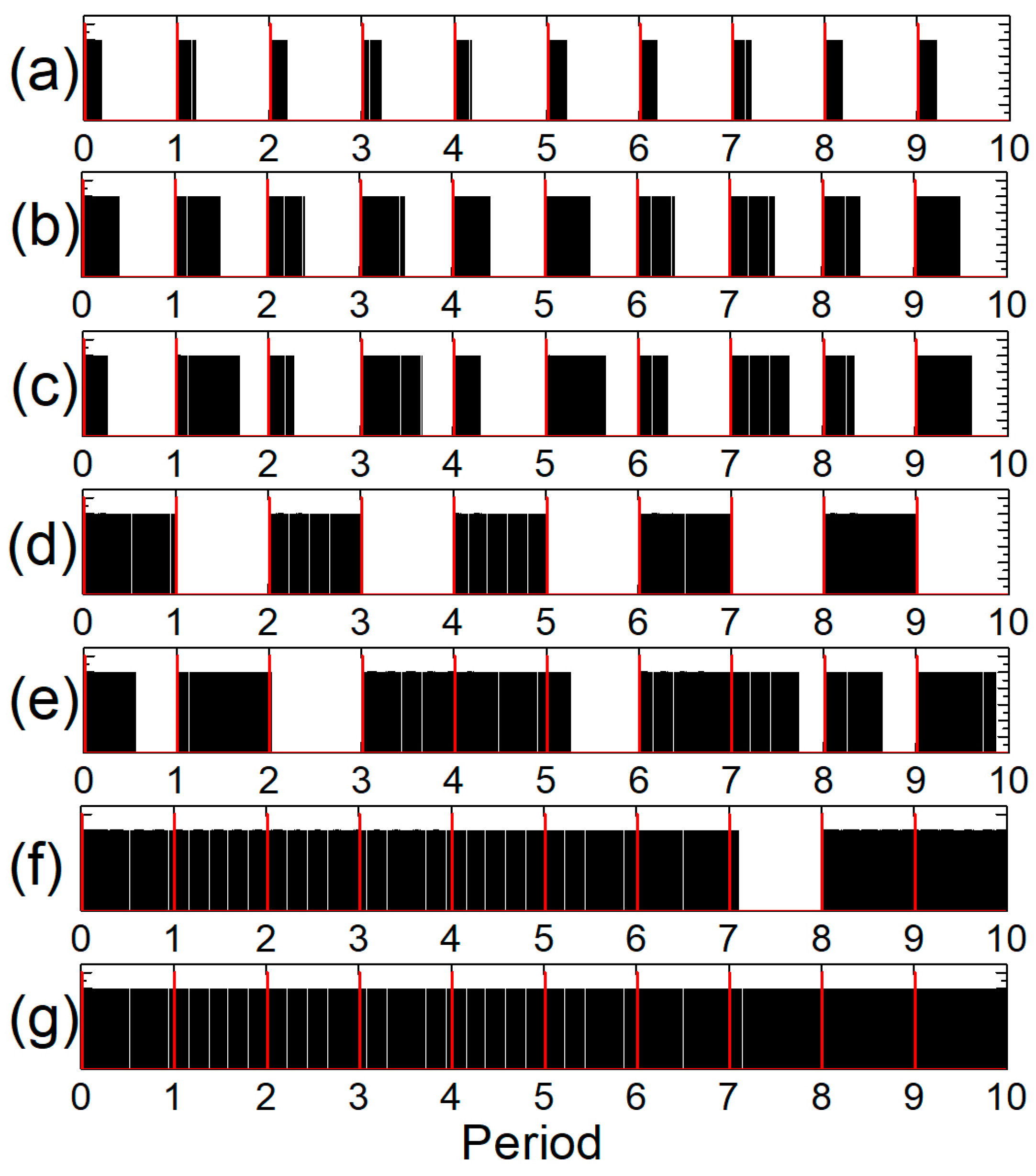
The shaping properties of periodic pulse sequences can be simulated using a very simple mathematical model, for which the program code can be written in a few lines, and similar results can be obtained, as shown in Figure 9 and Figure 10. The model includes a gain factor G that increases by a small amount A at each round-trip in the RC, i.e., G = G + A. This corresponds to continuous pumping. Whereas when a pulse is regenerated in the RC, the gain factor decreases by an amount B at each round-trip, i.e., G = G − B. And when the regenerated pulse does not circulate in the RC, then B = 0 and the gain factor does not decrease. Next, we set the condition that the pulse starts regenerating when the initial pulse is applied (a new period starts) and G > G0. Here G0 is the threshold gain factor below which the pulse is not completely regenerated and subsequently decays. Pulses continue to be regenerated after each round-trip when G > G0. When G < G0, pulse generation ceases. Furthermore, the values A and B can be a function of the gain factor, the number of round-trips, the pulse energy, etc. A and B must be positive. Figure 11 shows the pulse sequences when A and B (B = 0.001) are constant numbers. The threshold gain factor in the calculations was set to 10 and one period consisted of 100 regeneration cycles. As can be seen, when the ratio A/B is less than 4.5, pulse sequences of equal length are shaped in each period (Figure 11a). When the ratio A/B is 4.5, pulses are generated for half of the period (Figure 11b). When A/B > 4.5, then pulse sequence rearrangement starts and the pulse sequence lengths vary from period to period (Figure 11c–f). And finally, when A/B = 1, then all periods are completely filled with pulses, and a continuous sequence of pulses is generated over all periods.
As we can see, the simple mathematical model provides an excellent visualization of the generation of periodic pulse sequences in a pulse regenerative shaper when the pump power is limited.

4. Conclusions

In summary, an ultrashort light pulse regenerative shaper based on a closed-loop double-stage Mamyshev regenerator with electrically controllable acousto-optic switch was proposed and demonstrated. The unique feature of the ultrashort pulse regenerative shaper is that it shapes pulses with strictly defined parameters from rather different initial pulses. The energy and duration of the initial pulse can differ tens of times in comparison to the energy and duration of the shaped pulse. It was found experimentally that the energy of the regenerated pulse was almost independent of the energy of the initial pulse after three to seven round-trips. Due to its unique features, the ultrashort pulse regenerative shaper can be an attractive in practical applications where high-quality compressible ultrashort pulses with tunable pulse repetition rate are required. In addition, it was found that the generation of periodic pulse sequences with limited pump power can lead to a rearrangement of the pulse sequences, which results in variations in the length of the pulse sequence from period to period. The lengths of the pulse sequences in each period are equal until the pump power level is such that the lengths of the pulse sequences occupy less than half a period. We also proposed a simplified mathematical model for simulating periodic pulse sequences.

Author Contributions

Conceptualization, K.R.; methodology, K.R.; software, K.R.; validation, G.L., K.R. and J.Ž.; formal analysis, K.R.; investigation, G.L.; resources, K.R.; writing—original draft preparation, G.L.; writing—review and editing, J.Ž.; supervision, K.R.; project administration, K.R.; funding acquisition, K.R. All authors have read and agreed to the published version of the manuscript.

Funding

This project has received funding from European Regional Development Fund (project No. 01.2.2-LMT-K-718-03-0083) under a grant agreement with the Research Council of Lithuania (LMTLT).

Institutional Review Board Statement

Not applicable.

Informed Consent Statement

Not applicable.

Data Availability Statement

The data presented in this study are available on request from the corresponding author. The data are not publicly available due to further study.

Conflicts of Interest

The authors declare no conflict of interest.

References

  1. Hargrove, L.E.; Fork, R.L.; Pollack, M.A. Locking of He–Ne laser modes induced by synchronous intracavity modulation. Appl. Phys. Lett. 1964, 5, 4–5. [Google Scholar] [CrossRef]
  2. Ippen, E.P.; Shank, C.V.; Dienes, A. Passive mode locking of the cw dye laser. Appl. Phys. Lett. 1972, 21, 348–350. [Google Scholar] [CrossRef]
  3. Haus, H.A. Mode-locking of lasers. J. Sel. Top. Quantum Electron. 2000, 6, 1173–1185. [Google Scholar] [CrossRef]
  4. Gautam, V.; Drury, J.; Choy, J.M.C.; Stricker, C.; Bachor, H.A.; Daria, V.R. Improved two-photon imaging of living neurons in brain tissue through temporal gating. Biomed. Opt. Express. 2015, 6, 402–4036. [Google Scholar] [CrossRef] [PubMed] [Green Version]
  5. Charan, K.; Li, B.; Wang, M.; Lin, C.P.; Xu, C. Fiber-based tunable repetition rate source for deep tissue two-photon fluorescence microscopy. Biomed. Opt. Express. 2018, 9, 2304–2311. [Google Scholar] [CrossRef] [PubMed] [Green Version]
  6. Petkovšek, R.; Agrež, V.; Petelin, J.; Černe, L.; Bünting, U.; Podobnik, B. Pulses on demand in fibre and hybrid lasers. J. Mech. Eng. 2019, 65, 680–689. [Google Scholar] [CrossRef]
  7. Lau, K.Y. Gain switching of semiconductor injection lasers. Appl. Phys. Lett. 1988, 52, 257–259. [Google Scholar] [CrossRef]
  8. Lin, C.; Liu, P.L.; Damen, T.C.; Eilenberger, D.J.; Hartman, R.L. Simple picosecond pulse generation scheme for injection lasers. Electron. Lett. 1980, 16, 600–602. [Google Scholar] [CrossRef]
  9. Paulus, P.; Langenhorst, R.; Jager, D. Generation and optimum control of picosecond optical pulses from gain-switched semiconductor lasers. IEEE J. Quant. Electron. 1988, 24, 1519–1523. [Google Scholar] [CrossRef]
  10. Chen, K.K.; Price, J.H.V.; Alam, S.-u.; Hayes, J.R.; Lin, D.; Malinowski, A.; Richardson, D.J. Polarisation maintaining 100 W Yb-fiber MOPA producing µJ pulses tunable in duration from 1 to 21 ps. Opt. Express 2010, 18, 14385–14394. [Google Scholar] [CrossRef] [PubMed] [Green Version]
  11. Fu, W.; Wright, L.G.; Wise, F.W. High-power femtosecond pulses without a modelocked laser. Optica 2017, 4, 831–834. [Google Scholar] [CrossRef] [PubMed] [Green Version]
  12. Mamyshev, P.V. All-optical data regeneration based on self-phase modulation effect. In Proceedings of the 24th European Conference on Optical Communication. ECOC’98 (IEEE Cat. No.98TH8398), Madrid, Spain, 20–24 September 1998; Volume 1, pp. 475–476. [Google Scholar] [CrossRef]
  13. Närhi, M.; Fedotov, A.; Aksenova, K.; Fiebrandt, J.; Schönau, T.; Gerecke, M.; Gumenyuk, R. Design guidelines for ultrashort pulse generation by a Mamyshev regenerator. Opt. Express 2021, 29, 15699–15710. [Google Scholar] [CrossRef] [PubMed]
  14. Mamyshev, P.V. Method and Apparatus for All-Optical Data Regeneration. U.S. Patent 6,141,129, 31 October 2000. [Google Scholar]
  15. Regelskis, K.; Želudevičius, J.; Viskontas, K.; Račiukaitis, G. Ytterbium-doped fiber ultrashort pulse generator based on self-phase modulation and alternating spectral filtering. Opt. Lett. 2015, 40, 5255–5258. [Google Scholar] [CrossRef] [PubMed]
  16. Liu, Z.; Ziegler, Z.M.; Wright, L.G.; Wise, F.W. Megawatt peak power from a Mamyshev oscillator. Optica 2017, 4, 649–654. [Google Scholar] [CrossRef] [PubMed]
  17. Želudevičius, J.; Mickus, M.; Regelskis, K. Investigation of different configurations and operation regimes of fiber pulse generators based on nonlinear spectral re-shaping. Opt. Express 2018, 26, 27247–272624. [Google Scholar] [CrossRef] [PubMed]
  18. Samartsev, I.; Bordenyuk, A.; Gapontsev, V. Environmentally stable seed source for high power ultrafast laser. In Proceedings of the Components and Packaging for Laser Systems III, San Francisco, CA, USA, 2 February 2017; Volume 10085, p. 100850S. [Google Scholar] [CrossRef]
  19. Sidorenko, P.; Fu, W.; Wright, L.G.; Olivier, M.; Wise, F.W. Self-seeded, multi-megawatt, Mamyshev oscillator. Opt. Lett. 2018, 43, 2672–2675. [Google Scholar] [CrossRef] [PubMed]
  20. Zheng, J.C.; Yang, S.; Lau, K.Y.; Zhu, Z.W.; Li, L. Recent research progress of Mamyshev oscillator for high energy and ultrashort pulse generation. Opt. Fiber Technol. 2021, 67, 102691. [Google Scholar] [CrossRef]
  21. Repgen, P.; Wandt, D.; Morgner, U.; Neumann, J.; Kracht, D. Amplification of ultrafast pulses in an extended Mamyshev regenerator. In Proceedings of the Fiber Lasers XVII: Technology and Systems, San Francisco, CA, USA, 21 February 2020; Volume 11260, p. 112600P. [Google Scholar] [CrossRef]
  22. Agrawal, G. Nonlinear Fiber Optics, 3rd ed.; Academic Press: San Diego, CA, USA, 2001; pp. 51–55. [Google Scholar]
  23. Lægsgaard, J. Control of fibre laser mode-locking by narrow-band Bragg gratings. J. Phys. B-At. Mol. Opt. 2008, 41, 095401. [Google Scholar] [CrossRef]
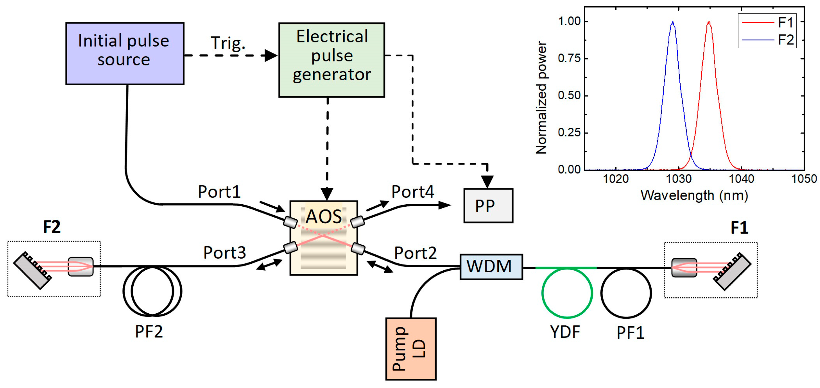
Figure 1. Experimental setup of the ultrashort light pulse regenerative shaper. The reflectance spectra of the filters F1 and F2 are shown in the top-right corner.
Photonics 10 00836 g001
Figure 2. Temporal profiles (a) and corresponding spectra (b) of shaped and initial pulses. The black continuous curve corresponds to the shaped pulse; dashed curves of different colors correspond to the initial pulses. The legend indicates the pulse energies and pulse durations or spectral widths at FWHM level. The mark ×3 means that the corresponding magnitude is actually three times larger than the one shown in the figure. BL—bandwidth-limited.
Photonics 10 00836 g002
Figure 3. (a) Energy of the regenerated pulse versus number of round-trips for different initial pulses (the legend indicates the initial pulses shown in Figure 2) and (b) numerically calculated temporal profile of the dechirped shaped pulse (continuous black trace) and a bandwidth-limited shaped pulse (dashed red trace).
Photonics 10 00836 g003
Figure 4. Pulse shaping from irregular multi-peaked initial pulses: (a) shaped single pulse and (b) shaped double pulse. The marks ×2 or ×10 mean that the corresponding magnitude is actually two or ten times larger than the one shown in the figure.
Photonics 10 00836 g004
Figure 5. Autocorrelation function of the initial (a) and the shaped (c) pulse. (b) Oscilloscope snapshot of the 30 round-trip pulse sequences.
Photonics 10 00836 g005
Figure 6. (a) Energy of the regenerated pulse versus number of round-trips (the total number of round-trips was 30 and the pump power was 96 mW) and (b) spectra of initial and shaped pulses at different energies of the initial pulse (the integrals of the spectra are proportional to the energy of the corresponding pulses).
Photonics 10 00836 g006
Figure 7. Temporal envelope of numerically calculated bandwidth-limited shaped pulse (dashed red trace) and temporal envelope of bandwidth-limited shaped pulse calculated from experimentally recorded shaped-pulse spectra (continuous black trace).
Photonics 10 00836 g007
Figure 8. Energy dependence of the regenerated pulse on the number of round-trips. Data were measured by setting 250 round-trips inside the RC. The repetition rate of the initial pulse was 10 kHz.
Photonics 10 00836 g008
Figure 9. Oscillograms of the ultrashort pulse regenerative shaper output versus pump power.
Photonics 10 00836 g009
Figure 10. Simulated oscillograms of the ultrashort pulse regenerative shaper output versus pump power. The pump power is indicated in the top-left corner of each oscillogram.
Photonics 10 00836 g010
Figure 11. Shaping of the periodic pulse sequences at different A/B: 0.2 (a), 0.45 (b), 0.48 (c), 0.5 (d), 0.7 (e), 0.9 (f), and 1 (g). B = 0.001, G0 = 10. One period consists of 100 regeneration cycles. The red-colored peaks represent the initial pulses.
Photonics 10 00836 g011
Disclaimer/Publisher’s Note: The statements, opinions and data contained in all publications are solely those of the individual author(s) and contributor(s) and not of MDPI and/or the editor(s). MDPI and/or the editor(s) disclaim responsibility for any injury to people or property resulting from any ideas, methods, instructions or products referred to in the content.