Communication

An All-Fiber FLRD System for SO2 Detection Based on Graphene-Coated Microfiber

1
CSG Electric Power Research Institute Co., Ltd., Guangzhou 510080, China
2
United Laboratory of Advanced Electrical Materials and Equipment Support Technology, CSG, Guangzhou 510080, China
3
Hubei Engineering Research Center for Safety Monitoring of New Energy and Power Grid Equipment, Hubei University of Technology, Wuhan 430068, China
*
Author to whom correspondence should be addressed.
Photonics 2023, 10(8), 863; https://doi.org/10.3390/photonics10080863
Submission received: 22 June 2023 / Revised: 13 July 2023 / Accepted: 18 July 2023 / Published: 25 July 2023
(This article belongs to the Special Issue Fiber Optics and Its Applications)

Abstract

:
The accurate and effective detection of SF6 decomposition components inside a gas-insulated switchgear (GIS) is crucial for equipment fault diagnosis and condition assessment. The current method for detecting SF6 decomposition components involves gas extraction at the GIS inlet, which only provides limited information on the decomposition component content. Therefore, there is a need to explore more effective ways to obtain internal gas component information within GIS. In this study, we propose a graphene-coated microfiber gas detection method for SO2. We establish a physical simulation model of the microfiber and analyze the sensing mechanism of the microfiber diameter and cladding refractive index changes in its evanescent field. A graphene-coated microfiber gas sensor was prepared using a drop-coating method, and a fiber loop ring-down (FLRD) gas detection system was constructed for the experimental studies on SO2 gas detection. The results demonstrated that the graphene-coated microfiber exhibits an excellent gas-sensitive response to SO2 and achieves trace-level detection at room temperature. The concentration range of 0 to 200 ppm showed good linearity, with a maximum detection error of 4.76% and a sensitivity of 1.24 ns/ppm for SO2. This study introduces an all-fiber method for detecting SF6 decomposition components, offering a new approach for online monitoring of SF6 decomposition components in GIS equipment using built-in fiber-optic sensors.

1. Introduction

With the construction of new power systems, the proportion of new energy generation is gradually increasing [1], and the demand for ultra-high voltage is steadily increasing. As an important transmission and substation equipment, GIS is also gradually increasing in number. It is necessary to ensure the safety and stability of GIS [2]. Partial discharge defects are one of the main causes of GIS failure, which causes SF6 gas to decompose at high temperatures and generate symbolic decomposition products such as SO2. Previous studies have shown that the identification and evaluation of partial discharge defects can be achieved by analyzing information such as the type, concentration, and growth trend of the SF6 decomposition components [3,4,5].
In order to achieve high sensitivity and accuracy in the detection of SF6 decomposition components, many scholars and experts have devoted themselves to the study of different methods, such as nanosensors [6,7], absorption spectroscopy [8,9], photoacoustic spectroscopy [10], and Raman spectroscopy [11,12]. However, these methods usually require sampling from the GIS inlet for external detection, which results in low concentrations of externally detectable components due to the large volume of the GIS gas chamber and the presence of adsorbents. Therefore, a new gas detection method needs to be considered to achieve online monitoring of the decomposition components inside the GIS.
Fiber-optic sensing technology, which combines the advantages of intrinsic safety, high immunity to electromagnetic interference, and good insulation performance, has been studied and applied in electrical equipment [12,13,14,15,16]. Graphene is a monolayer of two-dimensional crystalline materials composed of carbon atoms. It has good gas-sensitive performance and optical properties. With the use of graphene as an optical fiber cladding in combination with microfibers [17,18,19,20,21], the material can be evenly and smoothly attached to the surface of the microfiber, enhancing the interaction between the microfiber and the external environment, and is expected to achieve highly sensitive gas sensing [22,23,24,25]. Therefore, in this paper, we propose to prepare graphene-clad microfiber gas sensors by combining graphene thin-film materials with microfibers. A fiber loop ring-down (FLRD) gas detection system was constructed to explore the detection possibility of the typical feature decomposition gas, SO2. The results of this study can provide technical support for online SO2 gas monitoring using GIS equipment with built-in fiber-optic sensors.

2. Analysis of Gas Sensing Mechanism

The relationship between the energy distribution and core diameter of the microfiber was observed more clearly. The change in the effective refractive index of the microfiber was calculated when the incident wavelength was 1530 nm and the diameter changed from 1μm to 4μm, as shown in Figure 1 and Figure 2. The results showed that the effective refractive index of the microfiber gradually increased as the fiber diameter increased. The fiber core energy percentage showed rapid growth before 2.5 μm, increased slowly after 2.5 μm, and then at 3 μm, it approached saturation. The simulation showed that the smaller the diameter of the microfiber, the smaller the effective refractive index, the larger the evanescent field, and the weaker the field-binding force.
The refractive index of the external environment is also an important factor affecting the mode field energy distribution of the microfibers. In this study, graphene is used to replace the original air-cladding layer of microfibers. When a graphene film adsorbs different concentrations of SO2 gas, it causes a change in the refractive index of the material, which changes the optical field energy distribution of the microfiber. The diameter of the microfiber is 4 μm, and the refractive indices of the outside of the fiber are 1.1, 1.2, 1.3, and 1.4, respectively; the results are shown in Figure 3 and Figure 4. It can be seen that as the outside refractive index increases, the light field energy bound to the center of the fiber core gradually spreads outward, and the evanescent field range gradually becomes larger. Therefore, in actual sensor fabrication, we tend to choose microfibers with a smaller diameter or large external refractive index to achieve high-sensitivity sensing.

3. Experimental Platform Building

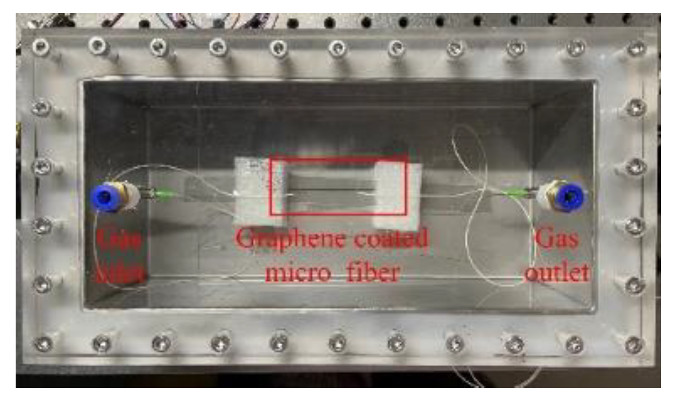
3.1. Sensor Preparation
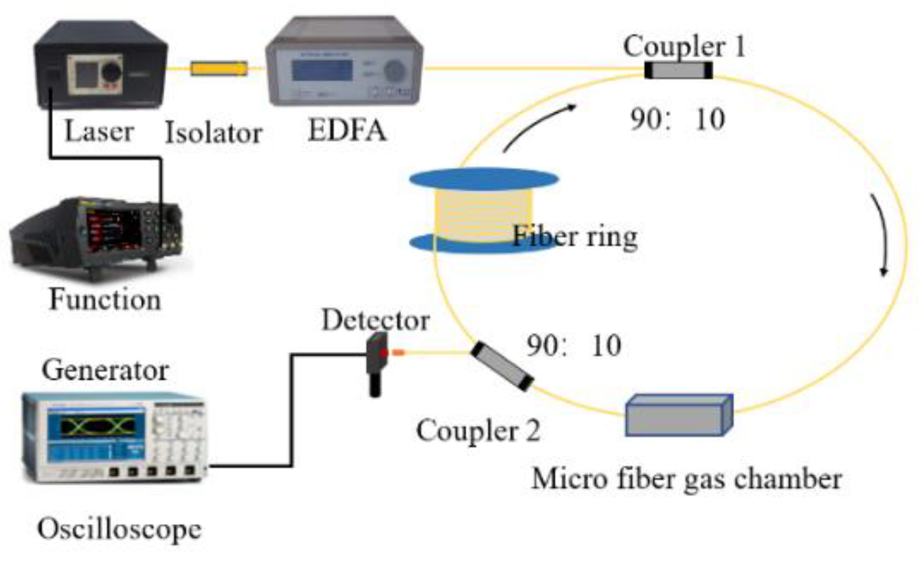
In this experiment, a single-mode fiber with a core diameter of 9 μm/125 μm was prepared using a flame-heated manual drawing approach. The platform construction is shown in Figure 5. The process included the following steps: remove the coating layer to ensure a smooth surface of the bare single-mode fiber; cut both ends of the fiber with a fiber cutting knife and perform loss-free fusion; place the bare single-mode fiber with the coating layer removed on the fiber fixing platform and fix it at both ends with fiber clamps; after preheating the bare single-mode fiber with an alcohol lamp until it is soft, stretch the single-mode fiber slowly and equably; during the stretching process, observe the change in the heated and stretched part of the middle section of the fiber, and ensure the uniform heating of the stretched part. Using this method, a microfiber with a stretching length of about 25 mm was produced for experimental use.
Graphene was coated on the microfiber sensing area as the fiber cladding material using a drop-coating method. After cleaning with deionized water, 0.3 mL of graphene oxide dispersion with a concentration of 10 mg/mL was taken and centrifuged to ensure uniform dispersion. Then, it was deposited uniformly on the conical waist area of the microfiber using a drop-coating method, followed by drying at 65 °C for 5 h in a vacuum drying oven to form a gas-sensitive film. When a thin film adsorbed different concentrations of characteristic gases, it changed the transmission loss of the coated microfiber if it caused a change in the refractive index of the material, enabling SO2 gas sensing. The processed coated microfiber was encapsulated in a gas chamber, as shown in Figure 6, and used to further build a sensing platform for experimental gas detection studies.

3.2. FLRD Platform

In this study, an all-fiber-optic gas sensing experimental platform was built based on the FLRD principle, and the platform structure is shown in Figure 7. The platform consisted of a function signal generator, laser (wavelength 1530 nm; power 20 mW), isolator, erbium-doped fiber amplifier, two 1 × 2 fiber couplers, coated fiber sensor, photodetector (response range 800~1700 nm; bandwidth 5 MHz), oscilloscope, fiber ring (1014 m), and single-mode fiber. Considering the different optical losses of couplers with different splitting ratios, the number of attenuated pulse signals was affected. After the previous theoretical and experimental verification, the 1 × 2 fiber coupler with the highest number of pulses and the highest peak pulse ratio of 10:90 was selected to obtain the best results. SO2 gas was selected as the detection object to test the gas sensing capability of the coated microfibers.
The incident laser energy entered the annular cavity via coupler 1, passed through the graphene-coated fiber-optic gas sensor, and then entered coupler 2. The laser energy was split into two parts in coupler 2. The majority of the laser energy passed through the annular cavity and then reentered coupler 1, circulating within the annular cavity. The other part of the laser energy was outputted to the photodetector, and finally, the decay waveform was outputted to the oscilloscope.

4. Analysis and Discussion

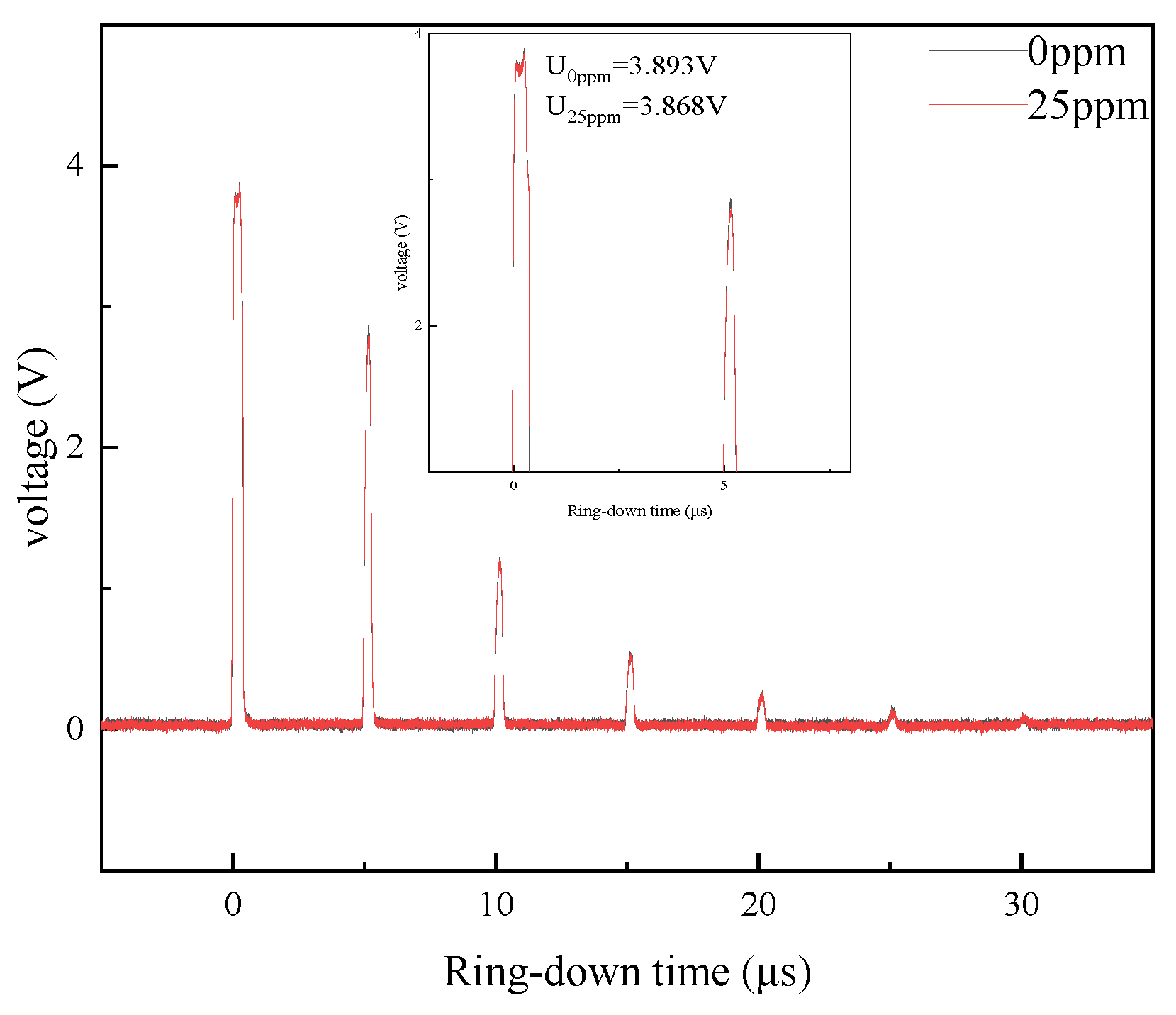
4.1. SO2 Gas Detection

A total of 25 ppm SO2 gas was selected for the experimental study, and the experiments were conducted at room temperature. N2 was used as the background gas, and the function signal generator was set to 10 kHz 5 Vpp pulses with a duty cycle of 2%. The waveforms of the light pulses of SO2 at 25 ppm and N2 background gas were measured to determine whether the coated microfiber has gas detection capability by observing the difference between the background gases. The experimental decay waveforms of N2 and 25 ppm SO2 in the gas chamber are shown in Figure 8. It was observed that when the microfiber was used as the sensor of the FLRD system, the intrinsic loss of the system was smaller and the number of pulses in the original pulse waveform was larger, so more accurate decay curve fitting results could be obtained. When the gas chamber is filled with SO2 gas, the intensity of each optical pulse amplitude decreased significantly, which indicates that the optical loss increases when the coated microfiber is exposed to SO2 gas, thereby increasing the system loss and decreasing the pulse signal amplitude.
Due to the strong evanescent field around the microfiber, it was sensitive to changes in the refractive index of the cladding. When the graphene coating material adsorbed the gas, its optical properties also changed accordingly, resulting in a reduction in the intensity of the light wave transmitted by the microfiber and an increase in the optical loss of the sensor. The FLRD system built in this study indirectly determined changes in the gas concentration by measuring the magnitude of the optical loss of the sensing unit.
The above experiments show that the system has the possibility of detecting SO2. For this purpose, a gas distributor (with an instrumental accuracy of 0.4% F.S and repeatability of ≤±0.4% F.S.) was used to further prepare SO2 gas at 50 ppm, 100 ppm, 150 ppm, and 200 ppm concentrations, and its data were recorded after the value of the gas dispenser was stabilized, and the pulse decay waveforms of SO2 gas at different concentrations were obtained. Finally, the exponential function was selected to fit the decay curve, as shown in Figure 9. It can be observed that the decay curves of SO2 gas at different concentrations show good regularity. The results of the linear fitting of the ring-down time with SO2 concentration at different concentrations are shown in Figure 10, where the fitted curve R2 is 0.994, which indicates that the linear relationship between the ring-down time and SO2 concentration is strong and that the graphene-coated microfiber has good detection ability for SO2, which can be used for SO2 gas detection at room temperature.

4.2. Errors Analysis

From the results of the above study, it was found that the FLRD gas detection system based on graphene-coated microfibers can detect SO2 gas at room temperature. In order to further understand the detection performance, five concentrations of SO2 gas at 25 ppm, 50 ppm, 100 ppm, 150 ppm, and 200 ppm were prepared again in this study using a gas distributor. After waiting for a period of time and when the value of the instrument was stable, the gas was passed into the gas cell for detection. The obtained ring-down time was substituted in the fitting curve of the ring-down time and SO2 concentration in Figure 10 with concentration inversion, and the obtained detection results are shown in Table 1. The maximum relative error was 4.76% in the detection of SO2 gas from 0 to 200 ppm.

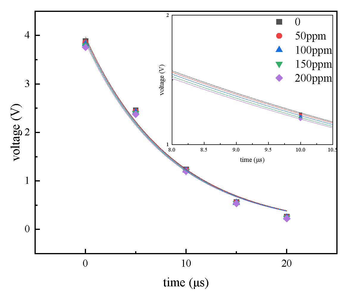
4.3. Sensitivity Analysis

Sensitivity represents the ability of a measuring instrument to respond to changes. It can be expressed as the corresponding change in the measuring instrument divided by the corresponding excitation change. In the present system, sensitivity was the ratio of the change in the ring-down time to the change in the gas concentration. This was calculated using the following equation:
S = Δ τ / Δ C
where S is the sensitivity, Δτ is the amount of change in ring-down time, and ΔC is the amount of change in concentration. Using this equation, the sensitivity of the system was calculated to be 1.24 ns/ppm.

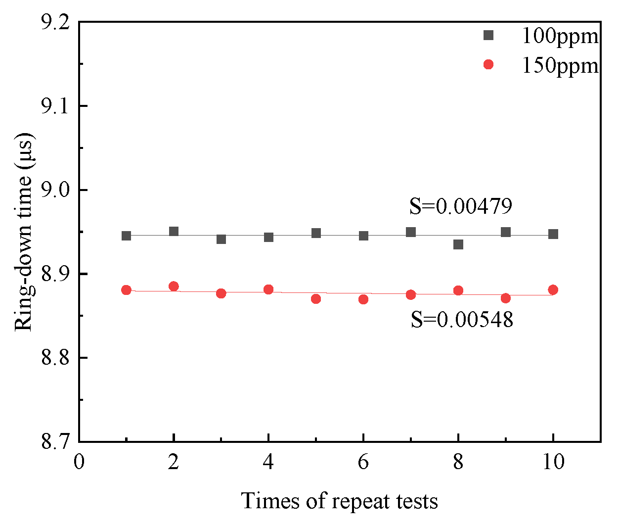
4.4. Stability Analysis

Finally, the two concentrations at 100 ppm and 150 ppm were selected to test the repeatability of the system. The SO2 gas was introduced into the gas chamber at 100 ppm and 150 ppm, and the values were recorded after the concentration in the gas chamber stabilized. The results are shown in Figure 11, the standard deviation was calculated to be 0.00479 at 100 ppm and 0.00548 at 150 ppm, indicating that the system has good repeatability, and the results of multiple measurements only fluctuate within a small range.

5. Conclusions

In this paper, a method of SF6 decomposition component detection based on a coated micro-optical fiber is proposed. Including the preparation of graphene-coated microfibers, the construction of the FLRD gas detection system, and the detection experiment of typical SF6 decomposition components, the following conclusions were obtained:
(1)
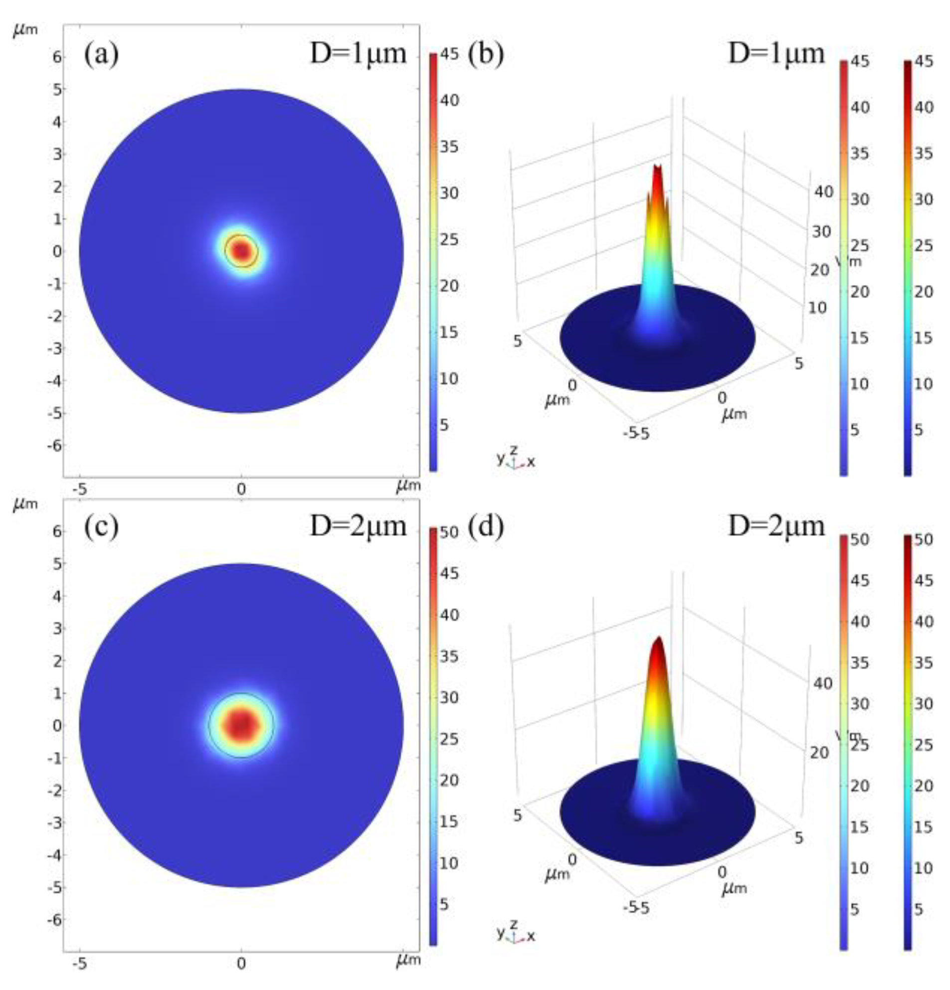
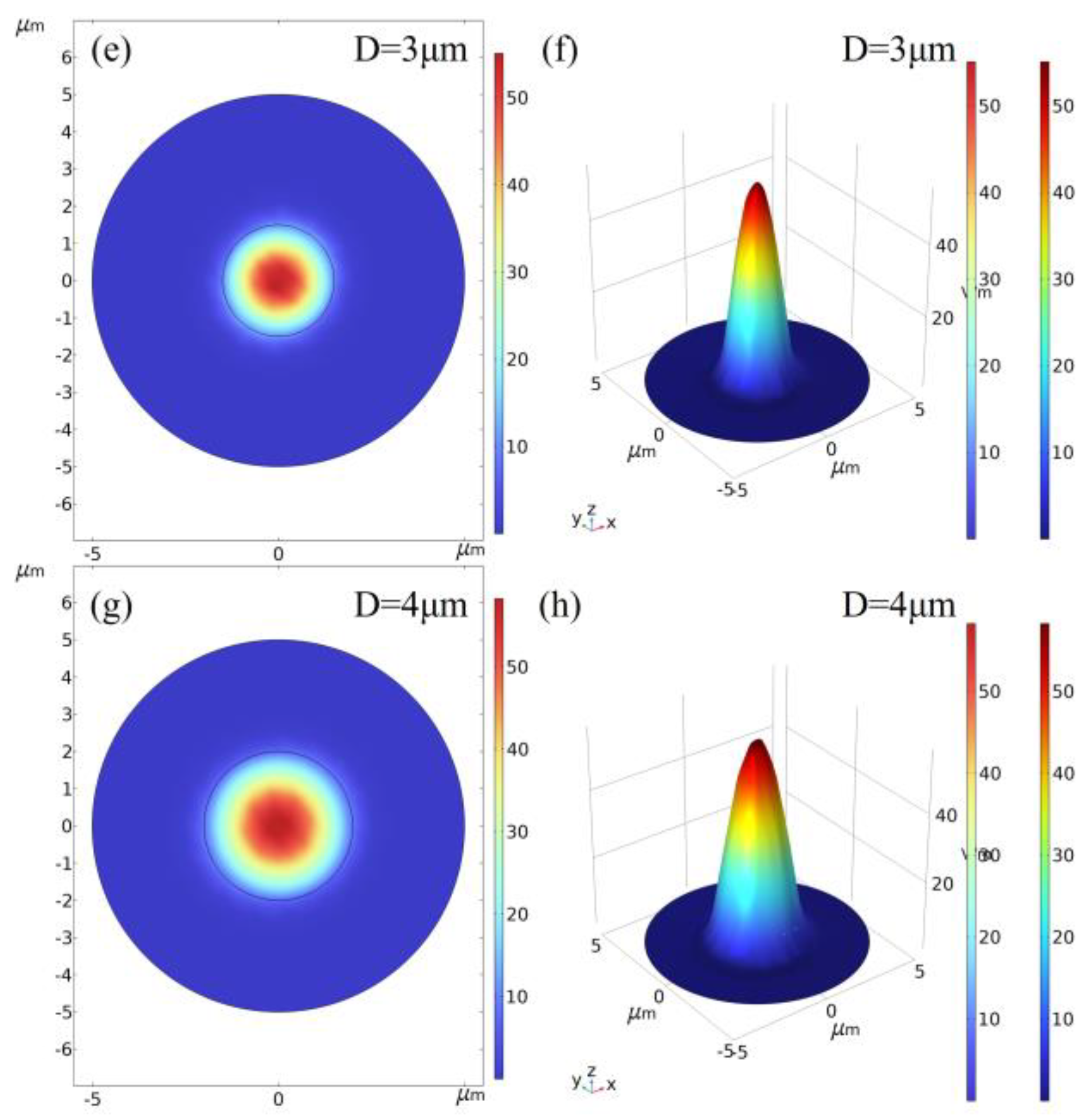
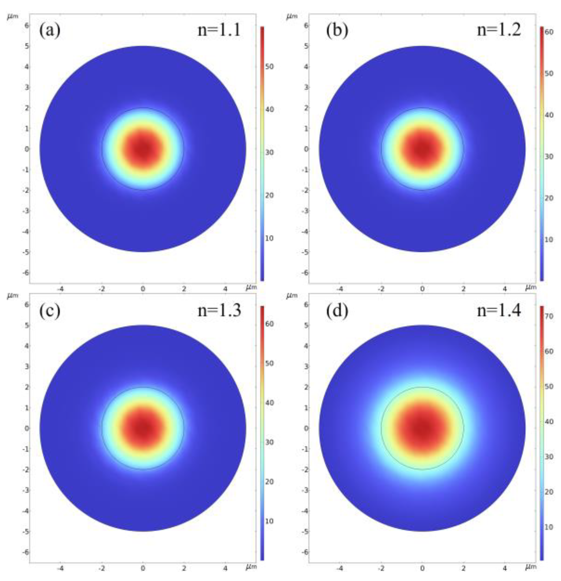
Microfibers with smaller diameters or larger external refractive indices contain less optical field energy in the core and a stronger evanescent field on the fiber surface.
(2)
The graphene-coated microfiber is sensitive to SO2 gas, and the optical loss of the graphene-coated microfiber increases as the SO2 concentration increases, which decreased the FLRD system ring-down time. There is a good linear relationship between the ring-down time and SO2 concentration, with an R2 of 0.994.
(3)
The FLRD gas detection system based on graphene-coated microfiber has a good detection performance for SO2, with a maximum error of 4.76% in the concentration inversion and a sensitivity of 1.24 ns/ppm within the range of 0~200 ppm.
The research results of this study illustrate the feasibility of coated microfiber sensors for detecting SF6 decomposition components. It also provides a more reliable and stable solution for the online detection of SF6 decomposition components in GIS equipment with built-in optical-fiber sensing technology.

Author Contributions

Conceptualization, D.W and Y.Z.; methodology, R.Z.; software, W.Y.; validation, D.W.; formal analysis, Z.H.; investigation, M.F.; resources, X.Z.; data curation, D.W.; writing—original draft preparation, Y.Z.; writing—review and editing, R.Z.; visualization, W.Y.; supervision, D.W.; project administration, X.Z.; funding acquisition, Z.H. All authors have read and agreed to the published version of the manuscript.

Funding

This research was supported by the United Laboratory of Advanced Electrical Materials and Equipment Support Technology, CSG, grant number CSGULAEMEST-2021-KF-02.

Institutional Review Board Statement

Not applicable.

Informed Consent Statement

Not applicable.

Data Availability Statement

Not applicable.

Conflicts of Interest

The authors declare no conflict of interest.

References

  1. Yang, D.; Tang, J.; Zeng, F.; Yang, X.; Yao, Q.; Miao, Y.; Chen, L. Correlation characteristics between SF6 decomposition process and partial discharge quantity under negative DC condition initiated by free metal particle defect. IEEE Trans. Dielectr. Electr. Insul. 2018, 25, 574–583. [Google Scholar] [CrossRef]
  2. Li, J.; Han, X.; Liu, Z.; Yao, X. A Novel GIS Partial Discharge Detection Sensor with Integrated Optical and UHF Methods. IEEE Trans. Power Deliv. 2018, 33, 2047–2049. [Google Scholar] [CrossRef]
  3. Zhang, H.; Zhang, G.; Zhang, X.; Tian, H.; Lu, C.; Liu, J.; Zhang, Y. PD Flexible Built-In High-Sensitivity Elliptical Monopole Antenna Sensor. Sensors 2022, 22, 4982. [Google Scholar] [CrossRef] [PubMed]
  4. Wu, Y.; Ding, D.; Wang, Y.; Zhou, C.; Lu, H.; Zhang, X. Defect recognition and condition assessment of epoxy insulators in gas insulated switchgear based on multi-information fusion. Measurement 2022, 190, 110701. [Google Scholar] [CrossRef]
  5. Zhang, X.; Zhang, Y.; Tang, J.; Cui, Z.; Li, Y.; Zhou, H.; Zhang, G.; Yang, J. Optical technology for detecting the decomposition products of SF6: A review. Opt. Eng. 2018, 57, 110901. [Google Scholar] [CrossRef]
  6. Cao, W.; Gui, Y.; Chen, T.; Xu, L.; Ding, Z. Adsorption and gas-sensing properties of Pt2–GaNNTs for SF6 decomposition products. Appl. Surf. Sci. 2020, 524, 146570. [Google Scholar] [CrossRef]
  7. Wang, J.; Zhou, Q.; Zeng, W. Competitive adsorption of SF6 decompositions on Ni-doped ZnO (100) surface: Computational and experimental study. Appl. Surf. Sci. 2019, 479, 185–197. [Google Scholar] [CrossRef]
  8. Aragoneses-Fenoll, L.; Montes-Casado, M.; Ojeda, G.; García-Paredes, L.; Arimura, Y.; Yagi, J.; Dianzani, U.; Portolés, P.; Rojo, J.M. Role of endocytosis and trans-endocytosis in ICOS costimulator-induced downmodulation of the ICOS Ligand. J. Leukoc. Biol. 2021, 110, 867–884. [Google Scholar] [CrossRef]
  9. Tian, J.; Zhao, G.; Fleisher, A.J.; Ma, W.; Jia, S. Optical feedback linear cavity enhanced absorption spectroscopy. Opt. Express 2021, 29, 26831–26840. [Google Scholar] [CrossRef]
  10. Rao, K.S.; Razdan, A.K.; Tyaki, A.; Chaudhary, A.K. Temperature dependent time resolved mid-IR photoacoustic spectroscopy of a nerve gas simulant DMMP. Spectrochim. Acta Part A Mol. Biomol. Spectrosc. 2018, 204, 696–701. [Google Scholar] [CrossRef]
  11. Hanf, S.; Keiner, R.; Yan, D.; Popp, J.; Frosch, T. Fiber-Enhanced Raman Multigas Spectroscopy: A Versatile Tool for Environmental Gas Sensing and Breath Analysis. Anal. Chem. 2014, 86, 5278–5285. [Google Scholar] [CrossRef] [PubMed]
  12. Ge, H.; Kong, W.; Wang, R.; Zhao, G.; Ma, W.; Chen, W.; Wan, F. A novel and simple technique of coupling a diode laser into a linear power build-up cavity for Raman gas sensing. Opt. Lett. 2023, 48, 2186–2189. [Google Scholar] [CrossRef]
  13. Chen, C.; Feng, W. Intensity-modulated carbon monoxide gas sensor based on cerium dioxide-coated thin-core-fiber Mach-Zehnder interferometer. Opt. Laser Technol. 2022, 152, 108183. [Google Scholar] [CrossRef]
  14. Liu, Z.; Wang, Y.; Chen, X.; Meng, X.; Liu, X.; Yao, J. An optical fiber sensing method for partial discharge in the HVDC cable system. Int. J. Electr. Power Energy Syst. 2021, 128, 106749. [Google Scholar] [CrossRef]
  15. Wang, L.; Zhou, J.; Chen, Y.; Xiao, L.; Huang, G.; Huang, X.; Yang, X. An intensity modulated fiber-optic carbon monoxide sensor based on Ag/Co-MOF in-situ coated thin-core fiber. Z. Nat. 2021, 76, 881–889. [Google Scholar] [CrossRef]
  16. Cheng, H.; Zhang, X.; Tang, J.; Xiao, S.; Wang, T.; Luo, B.; Tian, S. The application of fluorescent optical fiber in partial discharge detection of Ring Main Unit. Measurement 2021, 174, 108979. [Google Scholar] [CrossRef]
  17. Zhang, L.; Tang, Y.; Tong, L. Micro-/nanofiber Optics: Merging Photonics and Material Science on Nanoscale for Advanced Sensing Technology. iScience 2020, 23, 100810. [Google Scholar] [CrossRef] [Green Version]
  18. Zhang, X.; Yu, L.; Wu, X.; Hu, W. Experimental Sensing and Density Functional Theory Study of H2S and SOF2 Adsorption on Au-Modified Graphene. Adv. Sci. 2015, 2, 1500101. [Google Scholar] [CrossRef]
  19. Zhang, L.; Gu, F.; Lou, J.; Yin, X.; Tong, L. Fast detection of humidity with a subwavelength-diameter fiber taper coated with gelatin film. Opt. Express 2008, 16, 13349–13353. [Google Scholar] [CrossRef]
  20. Jia, L.; Wu, Y.; Yao, B.; Yang, F.; Rao, Y. A Sensitivity Enhanced Gas Sensor Based on Carbon Nanotubes Around Microfiber. In Proceedings of the Third Asia Pacific Optical Sensors Conference, Sydney, Australia, 31 January–3 February 2012; Volume 8351, pp. 457–463. [Google Scholar]
  21. Fu, H.; Wang, Q.; Ding, J.; Zhu, Y.; Zhang, M.; Yang, C.; Wang, S. Fe2O3 nanotube coating micro-fiber interferometer for ammonia detection. Sens. Actuators B Chem. 2020, 303, 127186. [Google Scholar] [CrossRef]
  22. Yao, B.; Wu, Y.; Jia, L.; Rao, Y.; Gong, Y.; Jiang, C. Mode field distribution of optical transmission along microfiber affected by CNT films with complex refraction index. J. Opt. Soc. Am. B 2012, 29, 891–895. [Google Scholar] [CrossRef]
  23. Zhou, Z.; Xu, Y.; Qiao, C.; Liu, L.; Jia, Y. A novel low-cost gas sensor for CO2 detection using polymer-coated fiber Bragg grating. Sens. Actuators B Chem. 2021, 332, 129482. [Google Scholar] [CrossRef]
  24. Zhang, Y.; Yu, W.; Wang, D.; Zhuo, R.; Fu, M.; Zhang, X. Carbon Monoxide Detection Based on the Carbon Nanotube-Coated Fiber Gas Sensor. Photonics 2022, 9, 1001. [Google Scholar] [CrossRef]
  25. Chen, D.; Tang, J.; Zhang, X.; Wu, P.; Li, Y.; Xiao, B.; Miao, Q.; Liu, K. WS2 Nanostructure-Based Gas Sensor for SF6 Decomposition Products: Experimental and First-Principles Study. IEEE Sens. J. 2022, 22, 20171–20176. [Google Scholar] [CrossRef]
Figure 1. Two− and three−dimensional optical field distributions at 1530 nm incident wavelengths for (a) 1 μm, (b) 1 μm, (c) 2 μm, (d) 2 μm, (e) 3 μm, (f) 3 μm, (g) 4 μm, and (h) 4 μm diameters of the microfiber in air medium, respectively.
Photonics 10 00863 g001aPhotonics 10 00863 g001b
Figure 2. Variation in effective refractive index with microfiber diameter.
Photonics 10 00863 g002
Figure 3. Two dimensional optical field distributions of a 4-μm-diameter microfiber with external refractive indices of (a) 1.1, (b) 1.2, (c) 1.3, (d) 1.4, at an incident wavelength of 1530 nm.
Photonics 10 00863 g003
Figure 4. Variation between the ratio of evanescent field and external refractive index for a microfiber with a 4 μm diameter at 1530 nm incident wavelength.
Photonics 10 00863 g004
Figure 5. Microfiber preparation platform.
Photonics 10 00863 g005
Figure 6. Gas chamber for the coated microfiber sensor.
Photonics 10 00863 g006
Figure 7. Platform construction drawing.
Photonics 10 00863 g007
Figure 8. Pulse waveform of N2 background gas and 25 ppm SO2 standard gas.
Photonics 10 00863 g008
Figure 9. FLRD ring-down curves of different concentrations of SO2.
Photonics 10 00863 g009
Figure 10. Curve fitting of ring−down time and SO2 concentration.
Photonics 10 00863 g010
Figure 11. System repeatability test.
Photonics 10 00863 g011
Table 1. SO2 inversion error analysis.
Actual Concentration (ppm)Inversion Concentration (ppm)Relative Error (%)
2525.552.20
5051.873.74
10095.494.51
150157.144.76
200201.160.58
Disclaimer/Publisher’s Note: The statements, opinions and data contained in all publications are solely those of the individual author(s) and contributor(s) and not of MDPI and/or the editor(s). MDPI and/or the editor(s) disclaim responsibility for any injury to people or property resulting from any ideas, methods, instructions or products referred to in the content.

