Article

Investigation of Hybrid Remote Fiber Optic Sensing Solutions for Railway Applications

1
Communication Systems, Graduate School, Istanbul Technical University, 34469 Istanbul, Turkey
2
Electrical, and Electronic Engineering Faculty, Electronics and Communication Engineering Department Istanbul, Istanbul Technical University, 34469 Istanbul, Turkey
3
Optiwave System Inc., Ottawa, ON K2E 8A7, Canada
*
Author to whom correspondence should be addressed.
Photonics 2023, 10(8), 864; https://doi.org/10.3390/photonics10080864
Submission received: 27 May 2023 / Revised: 28 June 2023 / Accepted: 14 July 2023 / Published: 25 July 2023
(This article belongs to the Special Issue Advanced Photonic Sensing and Measurement)

Abstract

:
Fiber optic sensing (FOS) has become a well-known technology in response to the rising demands of the railway transportation field despite the abundance of electronic sensing systems in the market. FOS application boasts an all-in-one solution that is both efficient and versatile. In order to enhance the understanding of the capabilities of FOS, this paper presents a hybrid fiber optic sensing system with an improved sensing ability to facilitate transportation applications for primary or secondary security interfaces. The hybrid sensing scheme incorporates two different sensing systems designed for long-distance applications. The first system employs a coding technique for the transmitted pulses, which provide information on train location through cross-correlation with the reflected pulses from fiber Bragg grating (FBG) sensors located along the railway. The proposed system can accurately predict the train’s location up to a precision of one cm. The second system examines the wavelength drift of the reflected signal from the FBG sensor affected by the train using a tunable optical filter and photodetector. It determines essential parameters such as the train’s location, speed, and direction by measuring the Bragg wavelength shift and its direction. The effect of the train movement and speed on the applied strain on the FBG sensor is calculated in this work and applied to the simulation to determine the train’s location, speed, and direction. A calibration table facilitates the correlation between the train speed and the shift in the FBG center wavelength, which helps ensure accurate results. The hybrid fiber optic sensing system is designed to facilitate railway transportation applications’ sustainability and security.

1. Introduction

Traditional sensing methods such as track circuits or balises (trackside RF devices used as a reference point for localization) face many difficulties in the field. In some cases, conventional solutions may not produce the proper event condition due to interference with some external event occurrences or surrounding electromagnetic interference. Point-based sensor systems require excessive sensors and cables for long-range systems, resulting in increased project costs. However, fiber optic sensing (FOS) systems give more flexibility as they continuously detect and prevent fatal accidents with the help of sensing the location of moving objects’ speed and size over long distances. Also, FOS has significant immunity to electromagnetic interference (EMI). Thus, due to its nature, FOS systems bring continuous sensing ability with a single fiber optic line. Generally, in every existing metro system, like İstanbul, the fiber optic line is installed for backup purposes and ready for sensing. FOS systems find implementation in areas such as railways, highways, bridges, military, building securities, and border guards. Optical time-domain reflectometer (OTDR) systems are part of FOS systems. They were first demonstrated in 1976 and 1977 [1,2,3]. OTDRs were introduced initially to detect reflection errors or deficiencies in fiber links, then used to check latency [4,5,6,7,8,9]. The cost of this technology has become cheaper with time as the cost of photonics components dropped dramatically.
Five essential criteria are required for a remote fiber optic sensing system, including (i) sensor accuracy, (ii) range, (iii) spatial resolution, (iv) sampling resolution, and (v) detection time. The repetition rate of the transmitted pulses in a FOS system correlates directly to the range of the sensed fiber. Sending a second pulse without receiving the back reflection of the first pulse might lead to location suspense. Spatial resolution is related to the response of the sensor to the transmitted pulse width and the time it needs to create the proper response, which is associated with the time elapsed during the formation of 10 percent to 90 percent of the signal to be measured. For example, the response is not entirely generated, as shown in Figure 1. The sampling resolution is related to the time between two consecutive samples of the received pulse. The sampling resolution needs to be two times smaller than the spatial resolution [10]. The performance of the sensing system is limited to the transmitted pulse energy and receiver’s sensing capabilities. The receiver’s sensitivity can be improved using coherent detection or photon counting. On the other hand, the range of the sensing system can be enhanced significantly by using optical frequency domain reflectometry (OFDR) techniques or pulse compression coding [11,12,13,14].
The two primary sensing applications used in railway sensing are FBG-based and distributed acoustic sensing (DAS)-based systems. DAS systems are recommended for long-reach sensing. However, they suffer from localization accuracy issues. Errors of up to 2.1 to 10 m or more are frequently permitted for the spatial resolution of DAS systems in long distances [15,16,17]. In the proposed hybrid system, we showed that FBG sensors could be used for long-range railway lines with much lower localization error (1 cm). We expect this accuracy to be slightly higher in practice depending on the electronics used in data processing.
A hybrid fiber optic sensing system is proposed and investigated in this work using commercial software. The system ensures localization calculation with two different outputs to increase accuracy and provide redundancy for safety assurance. Although a single system is used to localize moving objects to cut costs, we think dual systems are better for sustainability and safety. The proposed work examined using coding and FBG shift detection techniques to determine the location of moving objects with high resolution. We have examined the effect of the air pressure created due to train movement and applied a mathematical model to calculate the strain on the FBG sensors. The system is used for train localization determination with sub-one-meter resolution over a 50 km fiber length. The hybrid FOS system uses uniform FBG sensors distributed along the fiber. The analytical models of the FBG sensor used in the simulation tool include temperature, stress, and strain effects which cause a change in the grating optical reflection and transmission spectra, specifically a drift in the Bragg center frequency. In this paper, we only consider the strain effect as it is caused by the air pressure created due to the train passing by the FBG sensor. The system also uses modulated encoded pulses transmitted over the same optical fiber. The reflected pulses by the FBG sensors are cross-correlated with the reference pulses to provide the localization of FBGs for the sustainability and security of the system. The train location, speed, and movement direction are determined by monitoring the shift of the FBG center wavelength. A tunable optical filter and pin photodetector determine the wavelength shift. The effect of the train’s speed on the FBG sensor is introduced in this work as strain is applied to it. The applied strain on the FBG is used in the simulation to monitor the shift of the FBG center wavelength. Thus, the FBG center wavelength shift determines the train speed and movement direction. This paper aims to provide a better, secure, and sustainable sensing system.

2. Investigated Sensing System

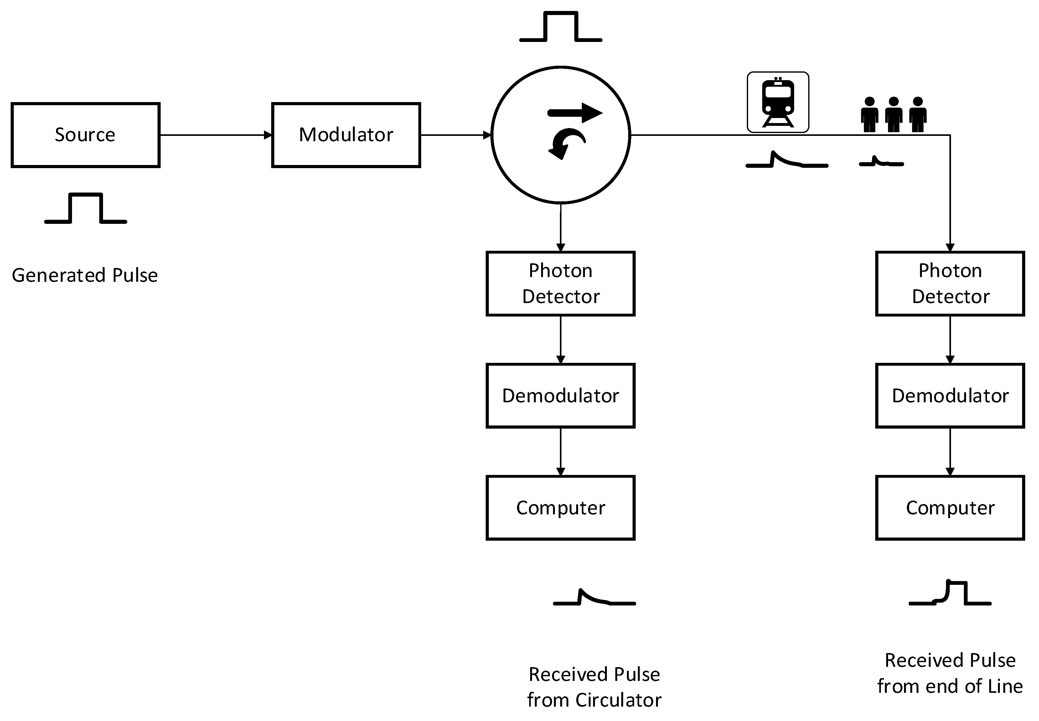
Figure 2 shows the general concept of FOS systems, which consists of different blocks. The first block is the transmitter subsystem, which incorporates the laser, electrical pulse source, encoder, and modulator to generate the optical pulse sequence launched into the fiber. The second part is the circulator that controls the direction of propagation of the launched optical pulses into the fiber and the backreflected signal from the FBG sensors for analysis. Groups of uniform FBG sensors at different center wavelengths are distributed along a 50 km fiber to generate the backreflected signal as the train passes them. The moving train causes air pressure at the location of the FBG sensor, which manifests as strain on the sensor. The last block in the FOS system is the receiver subsystem, which consists of the system’s photodiode, clock recovery, tunable optical filter, and data analysis. The receiver subsystem will determine the train speed, location, and direction of movement.

3. Train-Resistant Forces

The train resistance force is calculated based on the Davis equation suggested by the IEEE 1698 standard, which consists of static, kinetic, and air-resistant force [18]:
F(R) = (Krr × (M + Mload)) + (Fcoeff × (M + Mload) V) + ((Acoeff + Scoeff × (n − 1)) A × V2)
where F(R) is the train resistance force (N), Krr is the rolling resistance (N/kg), M + Mload is total train total mass (kg), Fcoeff is the flange coefficient (N/(kg km/h)), V is the train velocity (kmph), Acoeff is the frontal air drag coefficient (N/m2 kmph2), Scoeff is the skin effect air drag coefficient (N/m2 kmph2), n is the number of cars in the train set, and A is the frontal area of the train (m2). It should be noted that when a tunnel section is located along the train line, the last term of the equation is to be multiplied by the tunnel coefficient (kTunnel = 1.5 to 2), as typically used in metro applications. The last term represents the air-resistant force. The maximum air pressure is usually applied at the front side of the train. Air-resistant force calculation when a train passes through a tunnel at different train speeds is summarized in Table 1, where the force is given by
F(R_Air) = (Acoeff + Scoeff (n − 1)) A × V2 × kTunnel
Assuming Acoeff = 0.444829644, Scoeff = 0.12392, A = 8, n = 4 (total train length 125 m), and kTunnel = 1.75, the air pressure created by the train on the fiber cable with the FBG sensors with a diameter of 0.164 m and train speed of 80 km/h is given as
Train Air Resistant Force [N])/Cable Area [m2] = 5646/(12.5 × 0.164) = 2754 Pa
The pressure will cause a pull effect on the FBG sensor and strain it. The strain effect will cause a shift in the center wavelength of the FBG sensor.
Figure 3 illustrates the air pressure created in the front and back of the train during its movement in the tunnel. Compressive air pressure occurs in front of the train, and an expansion of air pressure is created in the back of the train. The maximum air pressure is created at the front of the train.
This work will focus on identifying and assessing the location of maximum strain in fiber Bragg gratings (FBGs). Our investigation will specifically concentrate on areas experiencing the highest air pressure. It is postulated that the highest pressure exerted on the train will be observed at both the anterior and posterior ends, covering a distance of roughly 10 to 15 m, in correlation with the train’s velocity and acceleration at 80 km per hour [19]. Our analysis adopted an estimation of 12.5 m as the average distance. Consequently, it becomes imperative to observe and analyze solely the FBGs situated in these particular regions. It is important to note that although the air pressure continues to exist and diminishes with increasing margin length, its influence on our calculations remains insignificant. Nonetheless, there is a possibility that it could serve as a factor for considering the presence of the train in future analyses.

4. General Setup and Base Design

In our work, we experimentally validated the models used in the simulation software in independent work. A governmentally funded project NSERC/Card1 538408-18 in 2019 was dedicated for that purpose [10]. A comparison between the experimental and simulated data obtained by the software for temperature and strain sensing is given in Table 2. The measurements were conducted over five different FBG sensor samples.
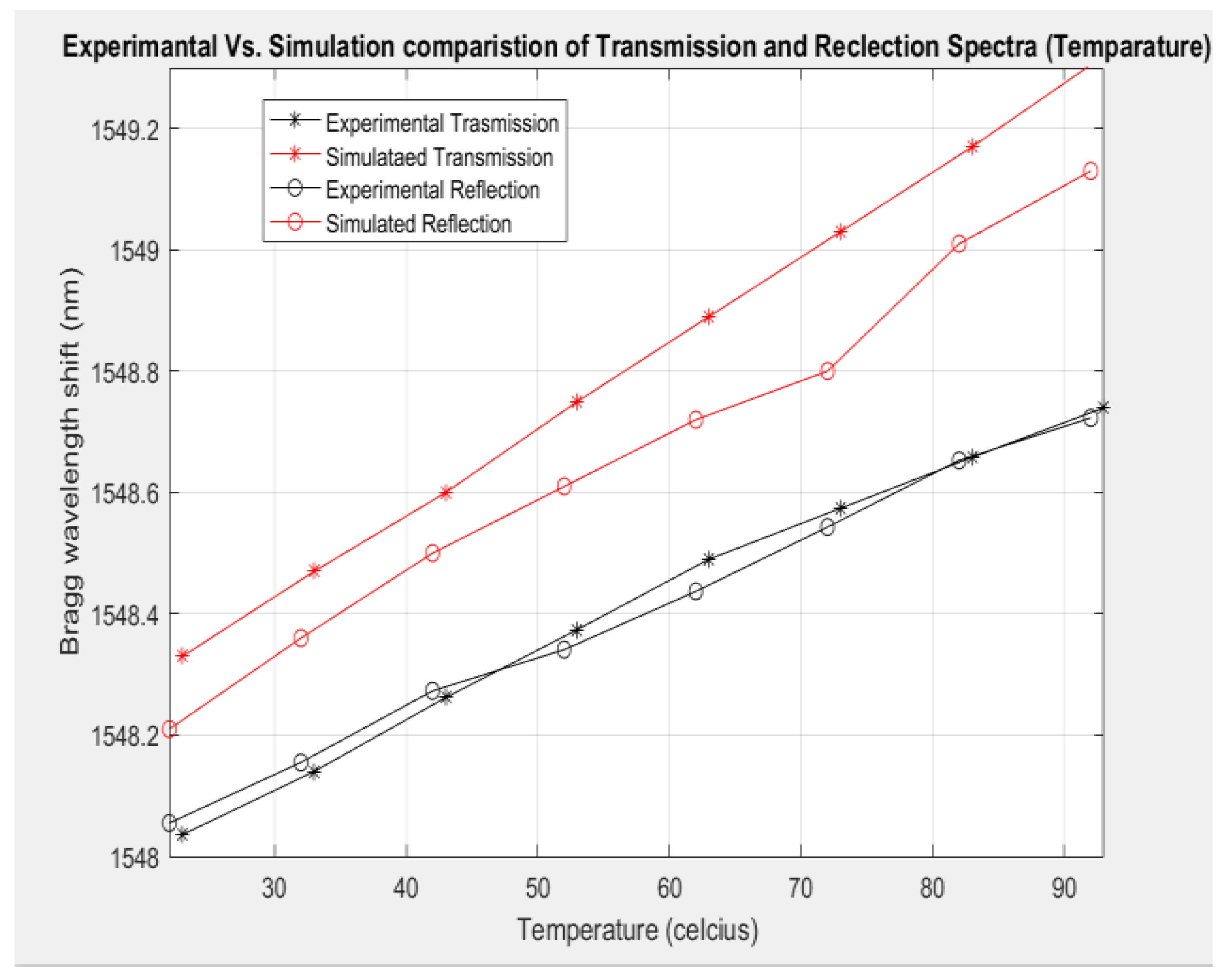
The sensing temperature was varied between 10 °C and 100 °C while the strain was varied from 0 to 0.012. The comparison of the results is shown in Figure 4 and Figure 5. The root mean square error (RMSE) is calculated for the measured data and summarized in Table 3. The error can be attributed to deviations from the actual central wavelength of the practical laser, the thermo-optic coefficient, and the photo-elastic coefficient from the ones used in the simulation. Figure 4 illustrates the Bragg wavelength shift for the transmission and reflection ports of the FBG sensor measured experimentally and simulated for different temperatures. On the other hand, Figure 5 shows the Bragg shift of the FBG sensor for different strain values measured and simulated using the OptiSystem software tool. It is clear that the simulation results are very close to the experimentally measured data, which provides credibility to the models used in the commercial software and assures that the simulations of the FOS systems are trustworthy.
Using FOS systems in train transportation is crucial for ensuring the safety and efficiency of train operations. The main objective of using these systems is to provide continuous monitoring and precise localization determination of trains. This is important because it allows for the real-time tracking of the train’s position, speed, and direction, which is essential for maintaining safety and efficient operations.
The coverage range and effectiveness of traditional sensing methods, which depend on sensors positioned at specific points, are limited. They can only provide information about the train’s location and speed within a limited area around the sensor [11]. However, hybrid FOS systems overcome these limitations by providing continuous and rapid monitoring of transportation operations. This is achieved using fiber optic sensors placed along the entire train track, allowing for real-time tracking of the train’s position and speed throughout the journey. Moreover, using hybrid FOS systems makes train transportation sustainable and safer. They can detect foreign objects, such as other vehicles, natural disasters, animals, or humans, which can cause fatal accidents. By detecting and alerting train operators to potential hazards in a timely manner, these systems help prevent accidents and ensure the safety of passengers and crew.
Figure 2 shows the block diagram of a moving object detection system with a fiber optic sensor exploiting the coded-pulse sequence transmission and groups of series of FBG sensors. Coding the generated pulses that propagate through the fiber link and are then backreflected at the FBG location improves the security and sustainability of the FOS system. Cross-correlation of the coded transmitted pulses with the backreflected pulses provides information on the location. The shift in the center wavelength of the FBG sensor at the train location provides information on the train’s speed and direction.
OptiSystem software is commercial software used to characterize the proposed hybrid sensing system. Table 4 shows the general parameters used to simulate the proposed hybrid sensing system. Choosing these parameters is significant for obtaining accurate results and avoiding misleading calculations, especially when choosing improperly sampled pulses or a time scale. The reference bit rate is set in this work to one-tenth of the transmitted pulse rate.
Figure 6 illustrates the transmitter (TX) section of the proposed system. It includes the laser, electrical pulse source, and modulator. The pulses are coded first using the 11101001 code and then modulated using a Mach–Zehnder modulator (MZM). The code indicates 62.5% of the pulses consist of ones. A 10 dBm laser source is used to carry the modulated pulses.
A three-port circulator is used to direct the launched pulses into the fiber and the backreflected signal from the FBG sensor that represents the moving object to the receiver, as shown in Figure 6. The moving object creates a strain action on the uniform FBG sensors, generating backreflected pulses propagating through the same fiber link. It is worth mentioning here that it is possible to use other types of FBG sensors, like apodized FBG sensors; however, we chose to use a typical sensor in this paper because we had experimentally validated them. A MATLAB component is used in the setup for cross-correlation calculation.

5. Transmitted Pulse Coding

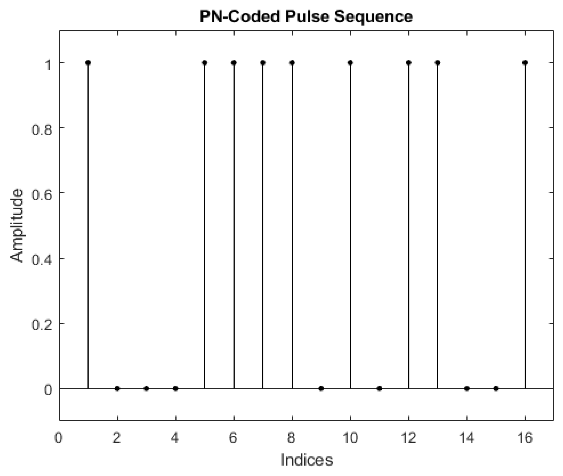
It is well known that a unique pseudo-noise (PN) code has been applied to transmitted pulses in GPS systems to improve localization accuracy via cross-correlation operation. Implementing the PN-Code helps sense signals even when they experience high noise levels. We have used 2, 4, 8, 16, 32, 64, 128, and 256 bits of the PN-Coding algorithm in the proposed sensing system. The coded transmitted pulses are cross-correlated with the backreflected pulses to determine the FBG location. Figure 7 shows a 16-bit coded pulse sequence in which the x-axis shows each coded bit (1 or 0) for 16-bits, while the y-axis shows the scaled output level. We could not try more than 256 bits for the PN-Code in this work because we have a computer with limited RAM. In this work, we have used PN-Code (similar to Golay code), which typically improves the SNR when the coding sequence size increases, offering better performance [12]. So, increasing the coding from 1 to 1024 bits or even more helps achieve more location accuracy, as shown later.
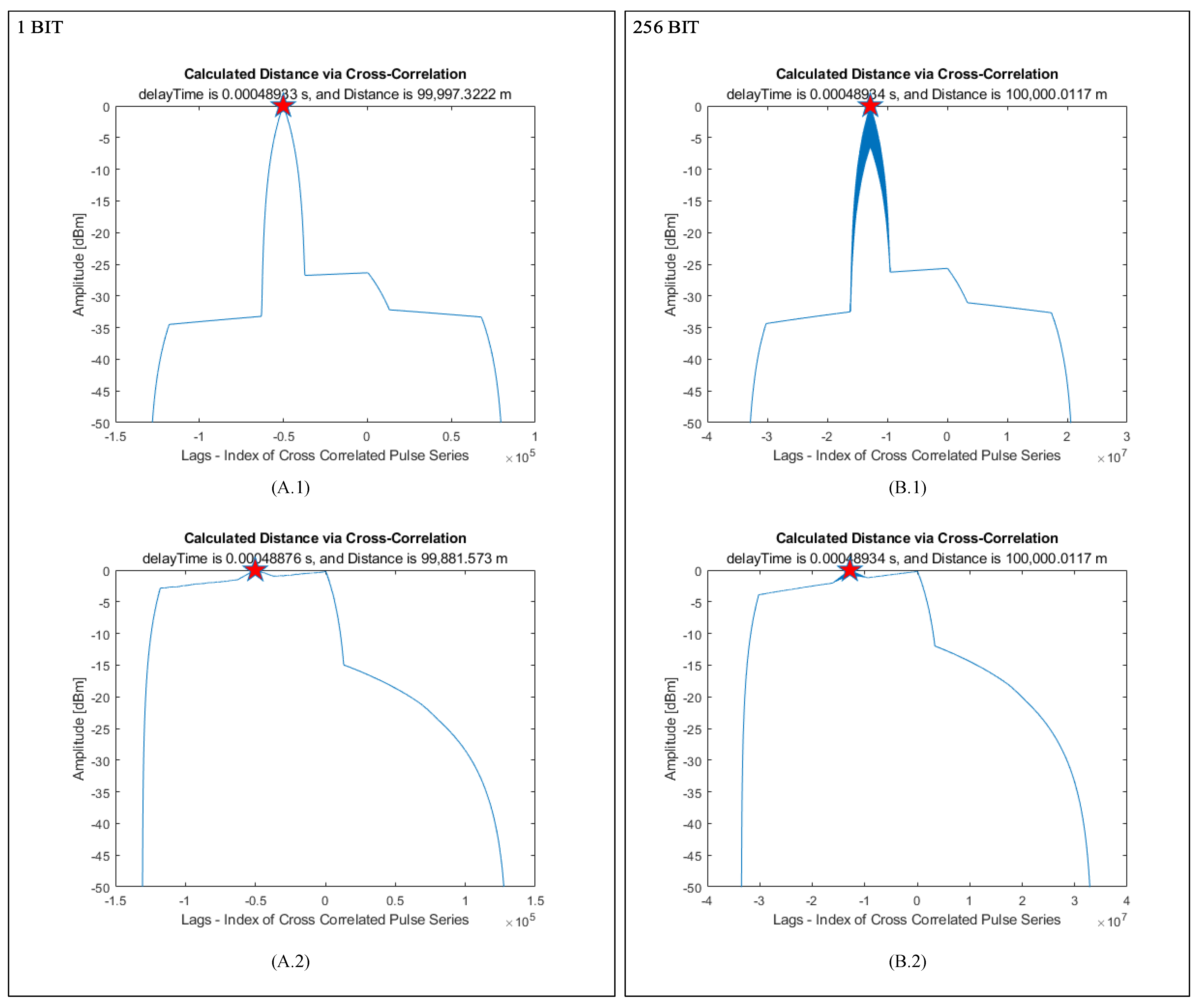
One of the FBG sensors is placed 50 km from the transmitter block. The transmitted pulses are initially coded and launched into the optical fiber. They reflect from the FBG sensor, propagate through the same fiber to the circulator, and arrive at the MATLAB component. We have examined the system’s performance with and without noise. The extremum points of the cross-correlation function for different datasets between 1 and 256 bits long are monitored. Gaussian noise is added to the backreflected signals using snr = −15, and kernel = awgn (kernel, snr, ’measured’) to make the system more realistic. The added Gaussian noise to the system has an amplitude of around ten times more than the backreflected signal level. Figure 8 shows the cross-correlation results with and without noise in the system. The results for a single-bit sequence pulse achieve around 118 m localization error resolution when the vibration event is 50 km away, as shown in Figure 8(A.2). If there is no noise in the system, the localization error is around 2.7 cm, as shown in Figure 8(A.1). However, a 256-bit pulse sequence offers a 1 cm localization error for an event 50 km away which is not affected by the noise as lower-bit-sequenced coding alternatives have shown in Figure 8(B.1,B.2). Using 256 bits coding helps avoid noise effects in the system. Hence, it helps in creating a more straightforward system with simple hardware. Figure 8(B.2) shows that the noise reduces the system lobe to around 0 dB, so the localization is much harder to achieve without coding. However, the calculated system lobe is around −25 dB without noise, as shown in Figure 8(B.1).
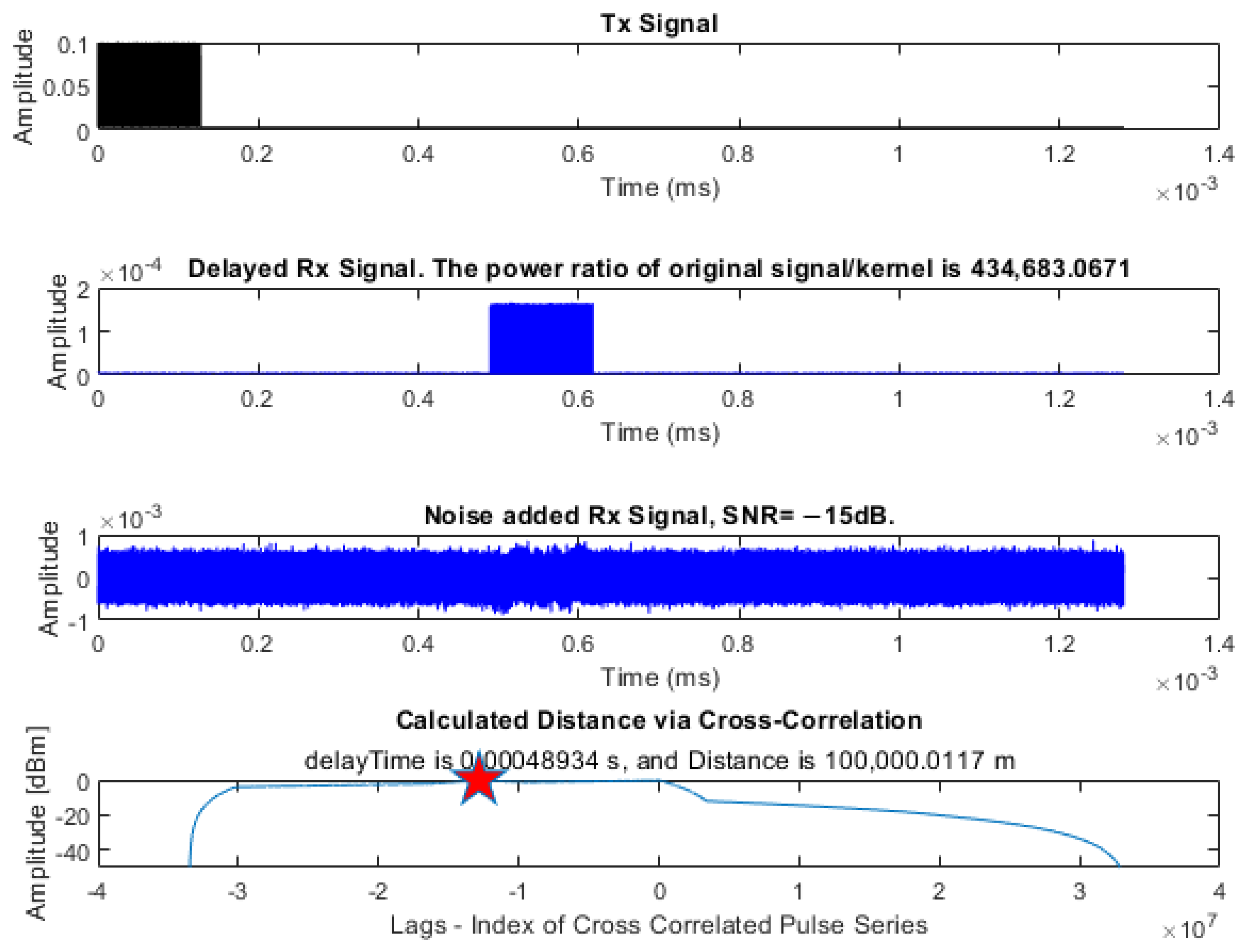
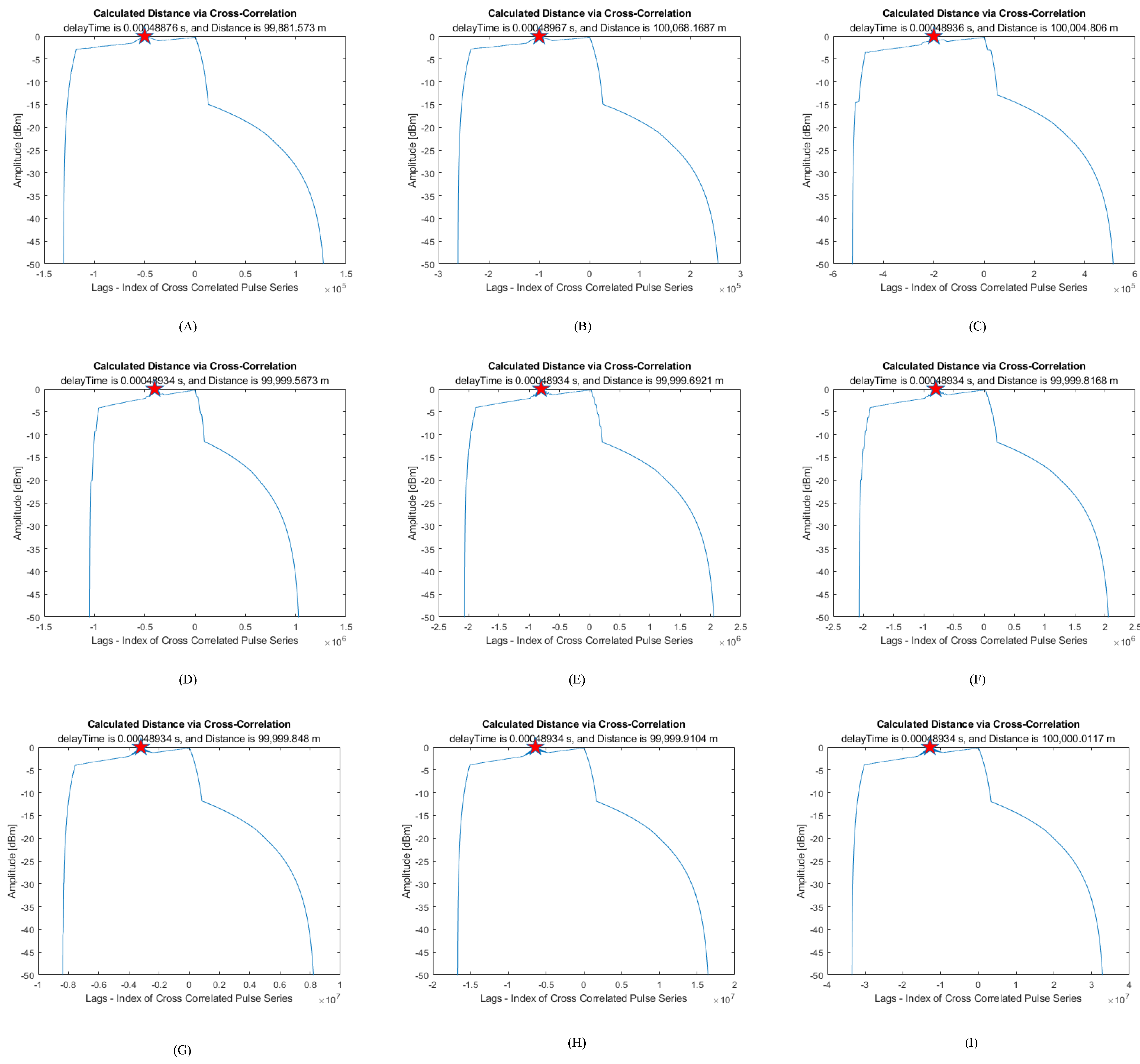
Figure 9 shows the transmitted (Tx) and backreflected (Rx) signals when applying Gaussian noise. The signal is attenuated around 105 times (−20 dB) compared to the Tx signal. Gaussian noise is added to the backreflected signal with an amplitude of about ten times (10 dB) more than the backreflected signal, which buries the backreflected signal in the noise. The mean power method will not work in this case. We have used the PN-Coding technique before the cross-correlation of the noise-added backreflected signal, which gives tremendously good results, as shown in the last trace of Figure 9. The result shows that the achieved localization error of the system is around 1 cm for a sensor 50 km away when a reflection event occurs with signal power so far below the noise level. Figure 10 illustrates the cross-correlation performances for 1-, 2-, 4-, 8-, 32-, 64-, 128-, and 256-bit coded pulse sequences. All sequences use the same timing frame; only the coding sequence length is changed.
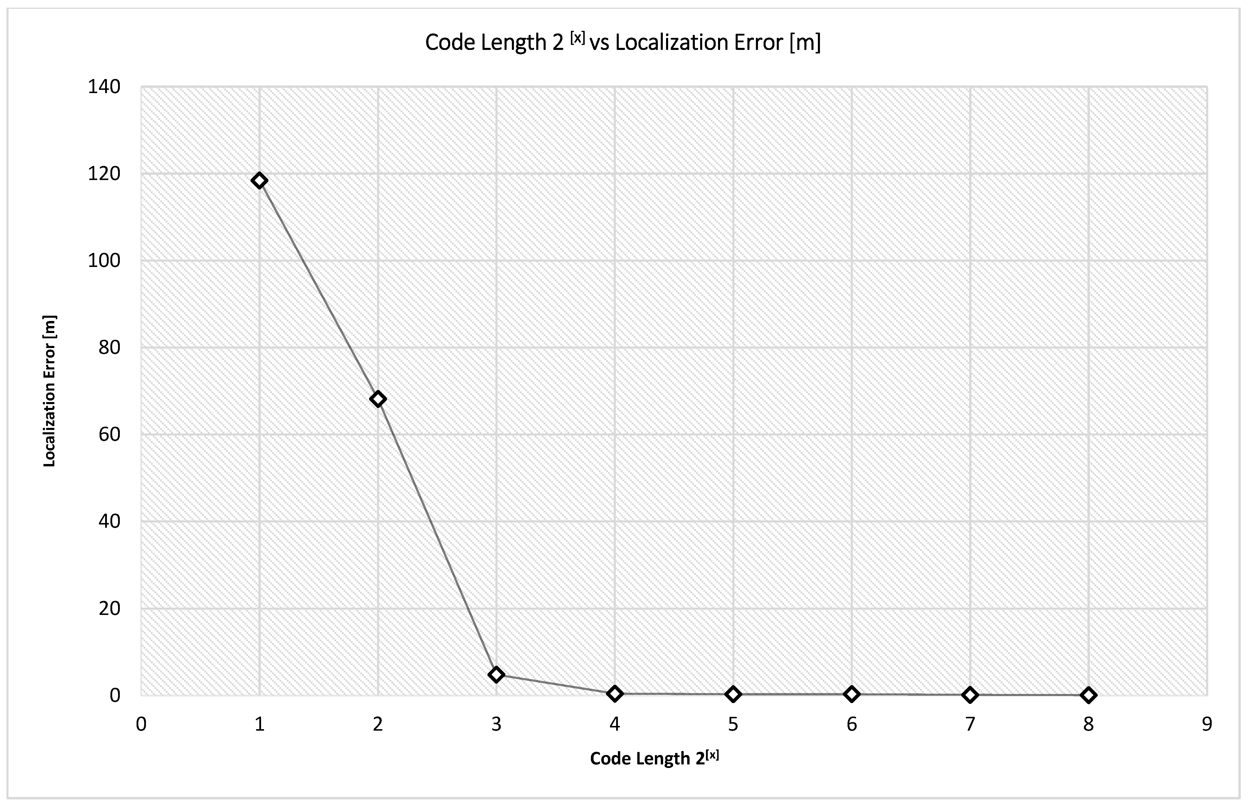
The localization errors when using a PN-Coding-related cross-correlation scheme in a noisy environment are around 118.4, 68.1, 4.8, 0.4, 0.3, 0.3, 0.2, and 0.1 m for 1-, 2-, 4-, 8-, 16-, 32-, 64-, 128-, 256-bit pulse sequences, respectively, when the sensor is 50 km away, as summarized in Figure 11.
Without noise, the sensing system achieves 0.12 m localization error for 50 km when an 8-bit code stream length is used. However, when using PN-Code in a noisy system, the localization error is around 4.5 m, as shown in Figure 11. The localization performance improves when the code length increases. However, it increases computing power demands.

6. Train Speed Detection Mechanism Using Bragg Shifting

The sensing mechanism of the train speed and movement direction arises primarily from the change in the Bragg wavelength of the FBG due to the physical effect applied to it. The FBG center wavelength is affected by environmental temperature, stress, and strain, where the change in λB can be described by [20].
(∆λB)/λB = (1 − pe)ε + (αTE + αTO)∆T
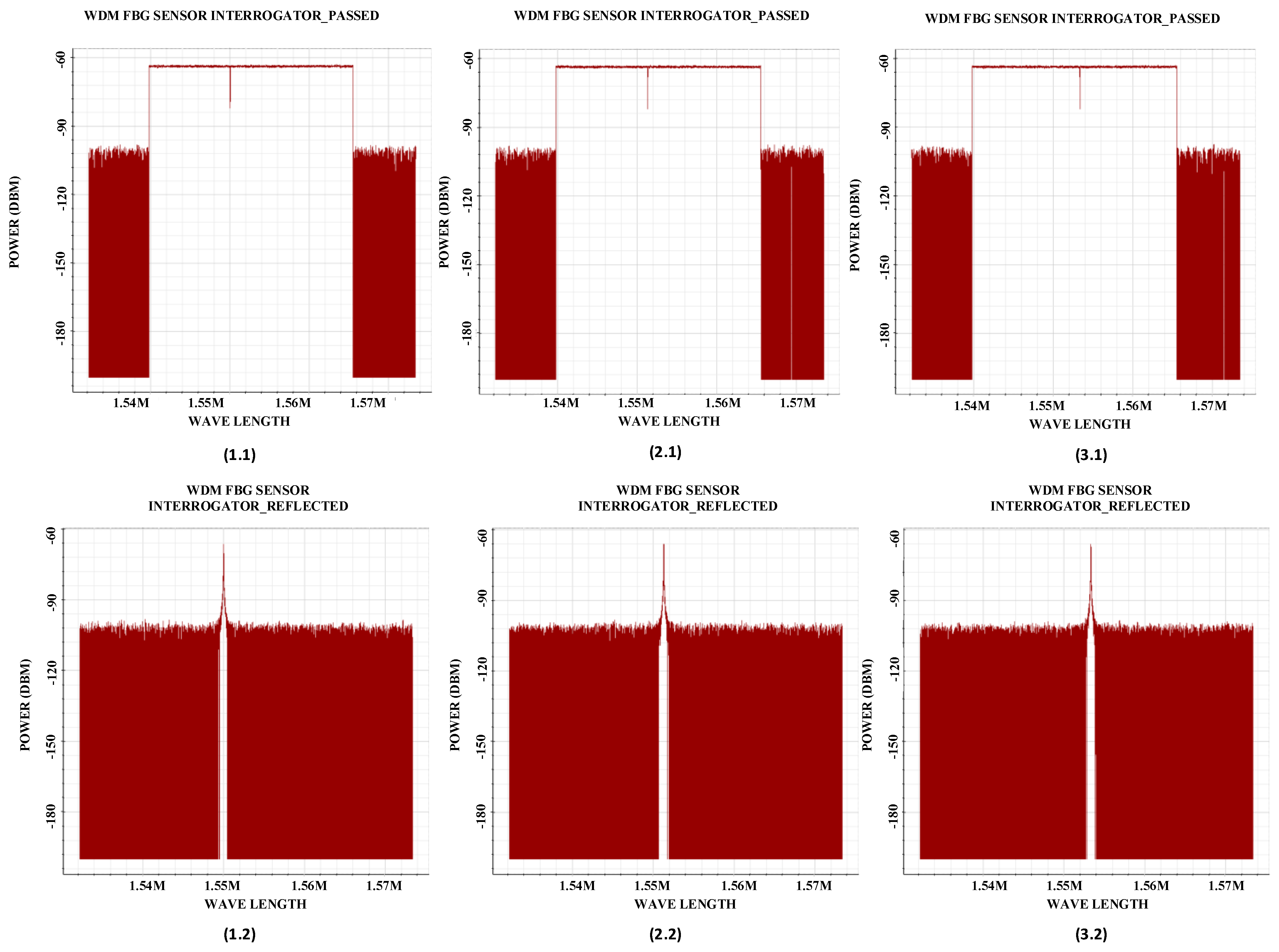
where ε is the longitudinal strain, ΔT is the temperature change, pe is the photo-elastic coefficient, αTE is the thermal expansion coefficient, and αTO is the thermo-optic coefficient. Figure 12 depicts the system used to characterize the train’s movement described in Figure 3. The train creates compressive air pressure at the front end, around 10% of the train length, creating different strain effects on the FBG sensor. Figure 13 shows the transmitted and reflected spectra for different train speeds. When the train velocity increases, the applied strain on the FBG sensor increases, and the FBG center wavelength shifts further. The amount of shift in the FBG center wavelength determines the train speed. The direction of the FBG center wavelength shift identifies the train’s movement direction.
Table 5 summarizes the parameters related to the FBG sensing system for different train speeds for an FBG located 50 km from the transmitter block. These parameters include the related time to pass 125 m, applied air force, FBG strain over cable at the sensing location, FBG shifted center wavelength, and power of the reflected signal. The used FBG center wavelength is 1550 nm. The reflected signal’s center wavelength shifts about 3.33 nm for 80 km/h. This paperwork ignores external environmental effects such as wind gusts; however, if other effects temporarily create enough stress over the fiber cable, it can be easily differentiated in the hybrid monitoring system, and an alarm could be triggered. This is another positive advantage of this proposed hybrid sensing system.

7. FBG Sensing Design

Five FBG sensors are used in the proposed hybrid time and frequency sensing scheme. The group of five sensors will be repeated as many times as needed in the railway path. We have tested a single group of sensors system used with the coding-related sensing system mentioned above.

General Layout of the FBG Design

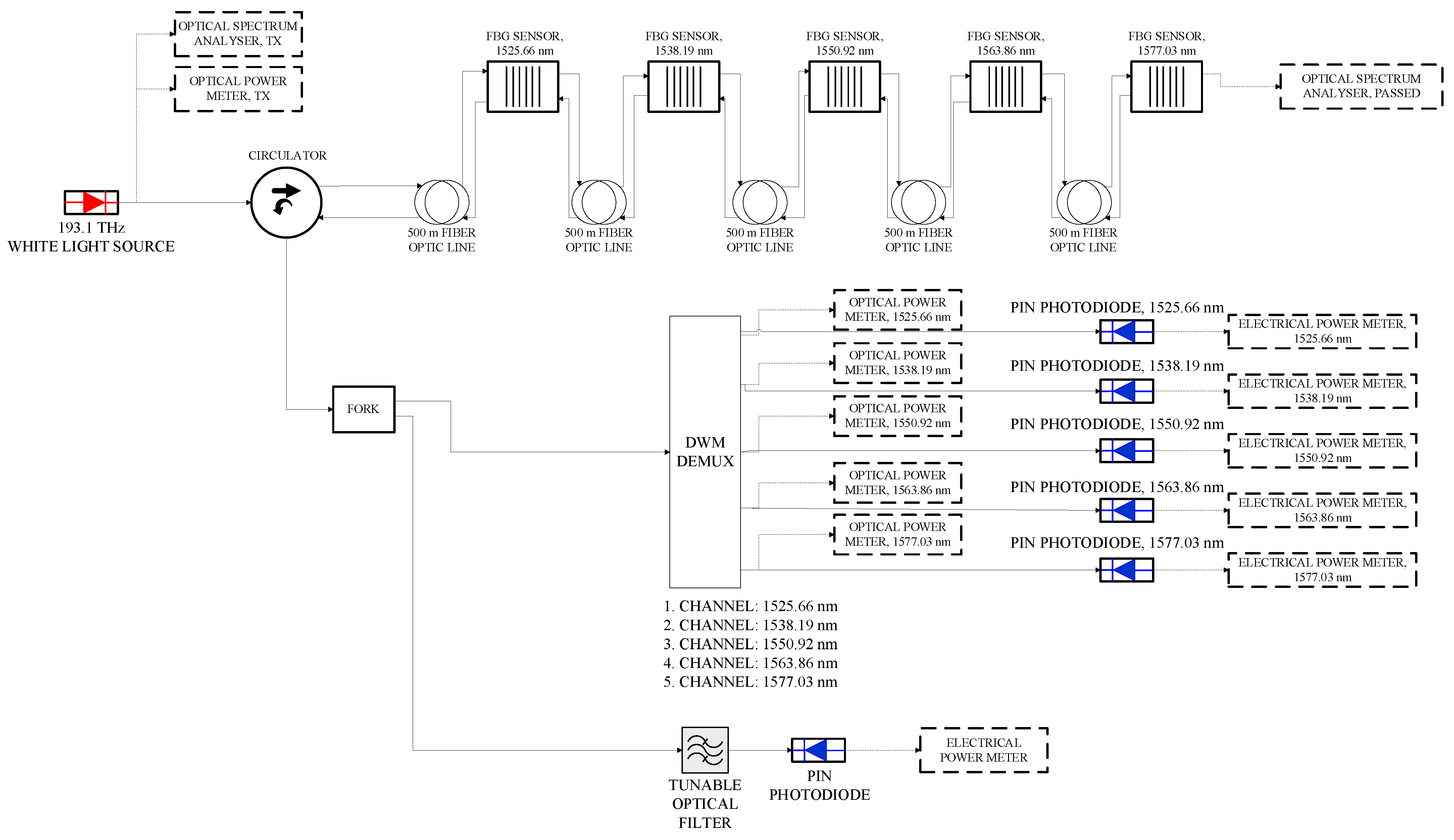
The proposed design of the FBG sensors system is shown in Figure 14, which consists of commercially available components, including a white light source that generates broadband noise centered at 193.1 THz and five uniform FBG sensors that operate at the wavelengths of 1525.66, 1538.19, 1550.92, 1563.86, and 1577.03 nm [21]. The closest FBG to the transmitter block is the 1525.66 nm FBG. A circulator directs the incident light into the FBG sensors and the reflected light to the receiver section. The detection system is designed to detect first the reflected light from all FBGs using a set of monitors that identify the peak power variation in the detected light for each FBG during the traveling of the train around the FBG sensor. Once the FBG with peak power variation is identified, a tunable filter is used to detect the wavelength shift of it caused by the strain applied on the FBG created by the air pressure of the train passing by the sensor.
Compressive air pressure exists in front of the train, and expansive air pressure exists at its back, which causes strain to the FBG sensors. The applied strain will shift the sensor’s Bragg wavelength, affecting the transmitted and reflected light. The maximum air pressure at the front of the train is around 2754 Pa. An equal negative air pressure exists at the back side of the train. The FBG Bragg wavelength shift would be to the right or the left side of its center wavelength, as shown in Figure 15. To avoid collision of backreflected signals, we have selected first the sensors’ Bragg wavelengths with margins to allow the system to operate safely at all train speeds up to 80 km/h. Then, we separated the location of the sensors by 500 m considering the length of the train, which is assumed to be 125 m. The relative frequencies and wavelengths for the used FBG sensors are described in Table 6.
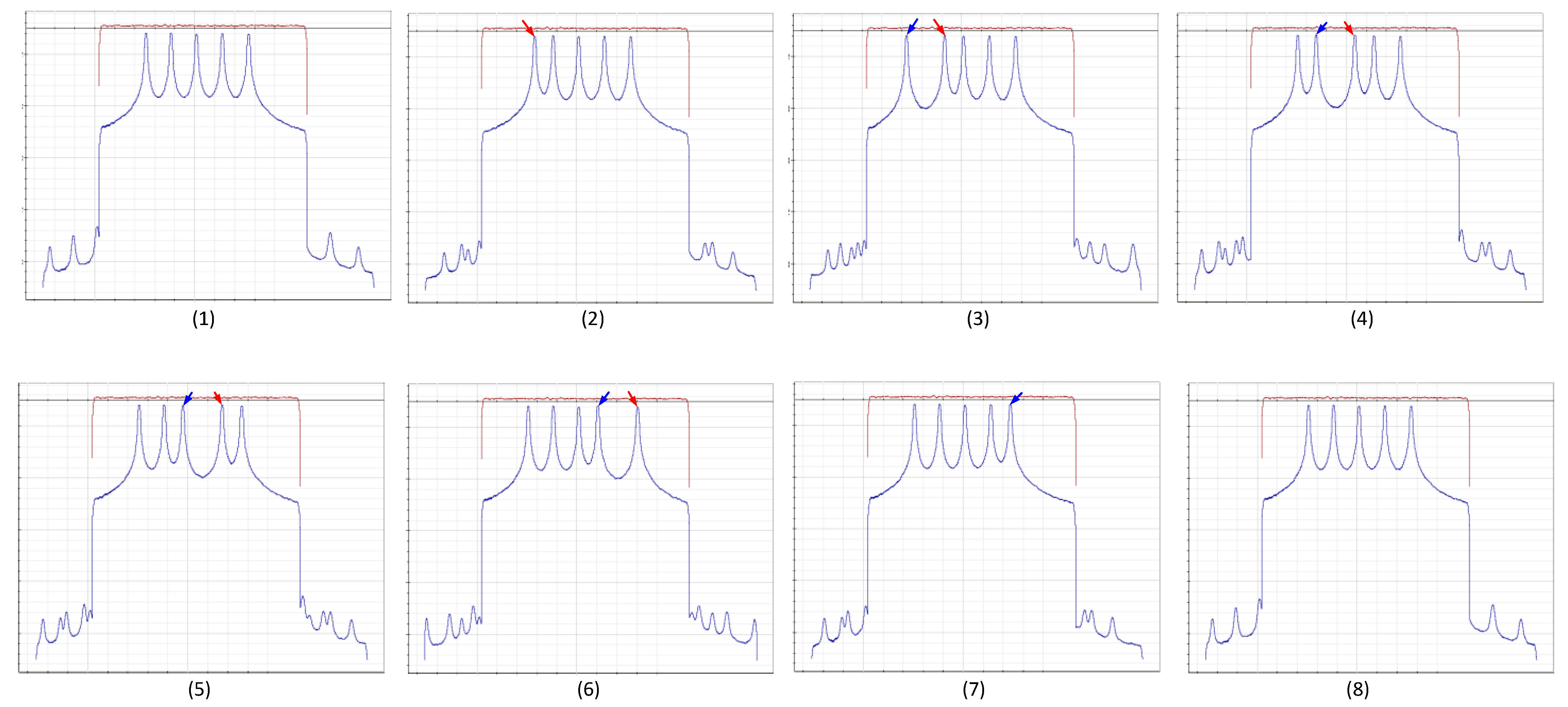
Figure 15 illustrates the transmitted (red) and backreflected (blue) spectra for the FOS sensors, showing the fifth sensor under strain. Figure 16 shows the effect of moving the train on all FBG sensors due to strain effects for the designed FOS system. The first (1) and last (8) images show the initial state without strain. Other sub-images show the spectra during the train movement. We consider in these results a maximum pressure of 2754 Pa (positive in the front and negative in the back of the train) and a train speed of 80 km/h. Only two neighboring FBGs can be activated at any given time. The red arrows indicate the compressive air pressure effect on the Bragg wavelength. In contrast, the blue arrows indicate the negative air pressure. The initial and final states show no pressure effect.
The hybrid sensing system is designed to detect the presence of trains and to track their speed and position as they travel through a tunnel. Table 7 shows the effect of moving the train on the applied air pressure on the different FBG sensors in the group. Table 8. shows the receiver total power changes at photodiodes while the train passes by the FBGs. The designed system assumes the train applies maximum air pressure (compression) on the first sensor in the FBG group (marked with red arrow) and maximum air pressure (expansion) on the back of the group (marked with blue arrow). In a real-life application, this state might not happen; however, we simulate it to observe any possible collision of the extremum frequency shifting in the system. The air pressure experienced on the different FBGs is calculated when the train moves at its maximum speed, assuming the sensors’ separation is 500 m and the train length is 125 m.
Table 8 presents the measured light power of the different photodiodes placed after a DEMUX with wavelengths of 1525.66, 1538.19, 1550.92, 1563.86, and 1577.03 nm. When the train is away from the sensor, there is no air pressure effect on the FBG, and the detected power is about −2.2 dBm. However, when the train passes by an FBG, it causes a considerable reduction in the power level (about −24 dBm). When two FBG sensors are affected by the train passing through a specific location, both pin detectors will detect close to −24 dBm. However, the Bragg wavelength shift of these gratings will be in the opposite direction. One will be to the right and the other to the left due to experiencing opposite air pressure. The shift of the Bragg wavelength of the affected sensor(s) can be identified using an optical tunable filter.
The FBG center wavelength shift can be determined by identifying the affected sensor through the detected power after the DEMUX, and then scanning the tunable filter around the Bragg center wavelength of the affected sensor to find the maximum power, as shown in Figure 17. The bandwidth of the optical tunable filter used in the simulation is 10 GHz. Increasing the filter bandwidth will increase the detected power level. However, it does not affect the sensing capability because it detects variation in power versus wavelength. The affected FBG sensor shown in Figure 17 is FBG 1, centered at 1525.66 nm. Point B shows the measured power when no air pressure is applied to the sensor. Thus, it is centered at 1525.66 nm. Point C shows the results caused by compressive air pressure; the reflection is centered at 1522.66 nm. Point A illustrates the results caused by expansive air pressure and the reflection centered at 1527.66 nm. The center wavelengths of the FBG sensors are selected far from each other to avoid overlaps due to shifting when a train passes by the sensor at maximum speed. So, the selection must be adequately made considering the extremum shifts caused by the train speed. The system can detect speeds up to 80 km/h with safe margins; however, if the speed of the train increases over 80 km/h (like 120 km/h), then the center wavelength of the FBGs shown in Table 6 and their location needs to be reconsidered to prevent the collision of backscattered signals. The operation of the system stays as is.
The algorithm for operating the hybrid system is as follows. First, the broadband light source is used in the system and launched into the series of five FBGs sensors with the same wavelengths. At the same time, each set of FBGs has a reflection coefficient chosen such that the light reflected from the last set of FBGs sensors would have roughly the same power level. The first set is expected to have 1% reflectivity, while the last set would have 99% reflectivity because 20 sets of FBG sensors are in the 50 km railway line. When there is no train, the power level for all pin detectors shown in Figure 14 would always be the same. When the train is present at any location, a shift in the center wavelength of the relative FBG causes a variation in the received power level that can be monitored, and the shift can be identified using the same circuit shown in Figure 14. As the discussion explains, the shift provides information on the train’s speed and moving direction. A fast switch at the transmitter between the broadband source and a tunable CW laser modulated with coded pulses is crucial in determining the train locations. The CW laser is tuned to the shifted center wavelength obtained in the first step. The backreflected pulses are cross-correlated with the reference transmitted pulses to determine the train location, as described in Section 5. Switching the used light in the system must be much faster than the train moving across the FBG sensor. When the train speed is 22.22 m/s (80 km/h), it takes about 5.6 s to pass away from the FBG sensor. This time is sufficient to handle switching the light sources and processing information for each source. Optical switches and pin detectors operate at micro- or sub-microsecond speeds.

8. Conclusions

A hybrid fiber optic sensing system that utilizes FBG sensors positioned at various locations on a train track has been demonstrated in this work. The first system uses the transmitted pulses’ coding technique to guarantee the sensing system’s sustainability and security, which ensures around 1 cm resolution under high noise. Cross-correlation between the backreflected pulses from the FBG sensor with the reference transmitted coded pulses is used to accurately predict the train’s location with a higher degree of accuracy than traditional methods. The system detection accuracy was investigated in the presence of high noise levels. Additionally, the train’s speed and movement direction are detected by monitoring the shift of the center wavelength of the FBG sensors using the second system, which provides the train location related to the fixed-point FBG sensor. The air pressure created by the train movement causes strain on the fiber cable that hosts a group of FBGs sensors. The affected FBG will experience a shift in its center wavelength to the right or the left, depending on the train’s moving direction. The hybrid sensing system can correlate the results of both systems to avoid external effects such as wind gusts or other unpredictable effects. This feature provides extra safety and security to the railway system.

Author Contributions

All authors have participated in the problem definition, theory, design, data analysis and collection, writing the paper. All authors have read and agreed to the published version of the manuscript.

Funding

This research received no external funding.

Data Availability Statement

Data could be provided up on the request of the individuals.

Conflicts of Interest

No conflict of interest for any of the authors.

References

  1. Barnoski, M.K.; Jensen, S.M. Fiber waveguides: A novel technique for investigating attenuation characteristics. Appl. Opt. 1976, 15, 2112–2115. [Google Scholar] [CrossRef] [PubMed]
  2. Barnoski, M.K.; Rourke, M.D.; Jensen, S.M.; Melville, R.T. Optical time domain reflectometer. Appl. Opt. 1977, 16, 2375–2379. [Google Scholar] [CrossRef] [PubMed]
  3. Personick, S.D. Photon probe—An optical time-domain reflectometer. Bell Syst. Tech. J. 1977, 56, 355. [Google Scholar] [CrossRef]
  4. Agrawal, P. Fiber-Optic Communication Systems, 3rd ed.; John Wiley & Sons: Hoboken, NJ, USA, 2012; pp. 57–58. [Google Scholar]
  5. Asawa, C.K.; Taylor, H.F. Propagation of light trapped within a set of lowest-order modes of graded-index multi-mode fiber undergoing bending. Appl. Opt. 2000, 39, 2029–2037. [Google Scholar] [CrossRef] [PubMed]
  6. Asawa, C.K.; Yao, S.-K. Microbending of Optical Fibers for Remote Force Measurement. U.S. Patent No. 4,412,979, 3 March 1983. [Google Scholar]
  7. Asawa, C.K.; Yao, S.K.; Stearns, R.C.; Mota, N.L.; Downs, J.W. High-sensitivity fibre-optic strain sensors for measuring structural distortion. Electron. Lett. 1982, 18, 362–364. [Google Scholar] [CrossRef]
  8. Yao, S.K.; Asawa, C.K. Microbending Fiber Optic Sensing; 1983 Technical Symposium East; SPIE: Bellingham, WA, USA, 1983; pp. 9–13. [Google Scholar]
  9. Griffiths, R.W. Structural Monitoring System Using Fiber Optics. U.S. Patent No. 4,654,520, 31 March 1987. [Google Scholar]
  10. Experimental Data Provided by Vendor OptiSystem Software under the Governmentally Funded Project NSERC/Card1 538408-18; OptiSystem: Nowy Sącz, Poland, 2019.
  11. Hartog, A.H. An Introduction to Distributed Optical Fibre Sensors; CRC Press: Boca Raton, FL, USA, 2017; pp. 6–38. [Google Scholar]
  12. Zan, M.S.D.; Elgaud, M.M.; Bakar, A.A.A. Coding the Optical Pulse in TDM-FBG Sensors with Hybrid Simplex-and Golay Codes for SNR Improvement. In Proceedings of the 2019 24th OptoElectronics and Communications Conference (OECC) and 2019 International Conference on Photonics in Switching and Computing (PSC), Fukuoka, Japan, 7–11 July 2019; pp. 1–3. [Google Scholar] [CrossRef]
  13. Ito, F.; Fan, X.; Koshikiya, Y. Long-range coherent OFDR with light source phase noise compensation. J. Light. Technol. 2012, 30, 1015–1024. [Google Scholar] [CrossRef]
  14. Geng, J.; Spiegelberg, C.; Shibin, J. Narrow linewidth fiber laser for 100-km optical frequency domain reflectometry. IEEE Photon. Technol. Lett. 2005, 17, 1827–1829. [Google Scholar] [CrossRef]
  15. Xiong, J.; Wang, Z.; Wu, Y.; Wu, H.; Rao, Y. Long-distance distributed acoustic sensing utilizing negative frequency band. Opt. Express 2020, 28, 35844–35856. [Google Scholar] [CrossRef] [PubMed]
  16. He, Z.; Liu, Q. Optical Fiber Distributed Acoustic Sensors: A Review. J. Light. Technol. 2021, 39, 3671–3686. [Google Scholar] [CrossRef]
  17. Sun, Y.; Li, H.; Fan, C.; Yan, B.; Chen, J.; Yan, Z.; Sun, Q. Review of a Specialty Fiber for Distributed Acoustic Sensing Technology. Photonics 2022, 9, 277. [Google Scholar] [CrossRef]
  18. IEEE Std 1698-2009; IEEE Guide for the Calculation of Braking Distances for Rail Transit Vehicles. IEEE: New York, NY, USA, 2009; pp. 1–41. [CrossRef]
  19. Izadi, T.; Abouali, O.; Mehrabian, M.A.; Salmanzadeh, M. Investigation of the effects of different parameters on the generated pressure waves inside the tunnels. SN Appl. Sci. 2020, 2, 1406. [Google Scholar] [CrossRef]
  20. Werneck, M.; Allil, R.; Ribeiro, B.; de Nazaré, F. A Guide to Fiber Bragg Grating Sensors; Intec Open Science: London, UK, 2013. [Google Scholar] [CrossRef] [Green Version]
  21. FS.COM Community. CWDM/DWDM ITU Channels Guide. FS.COM News. Available online: https://community.fs.com/news/cwdmdwdm-itu-channels-guide.html (accessed on 22 June 2023).
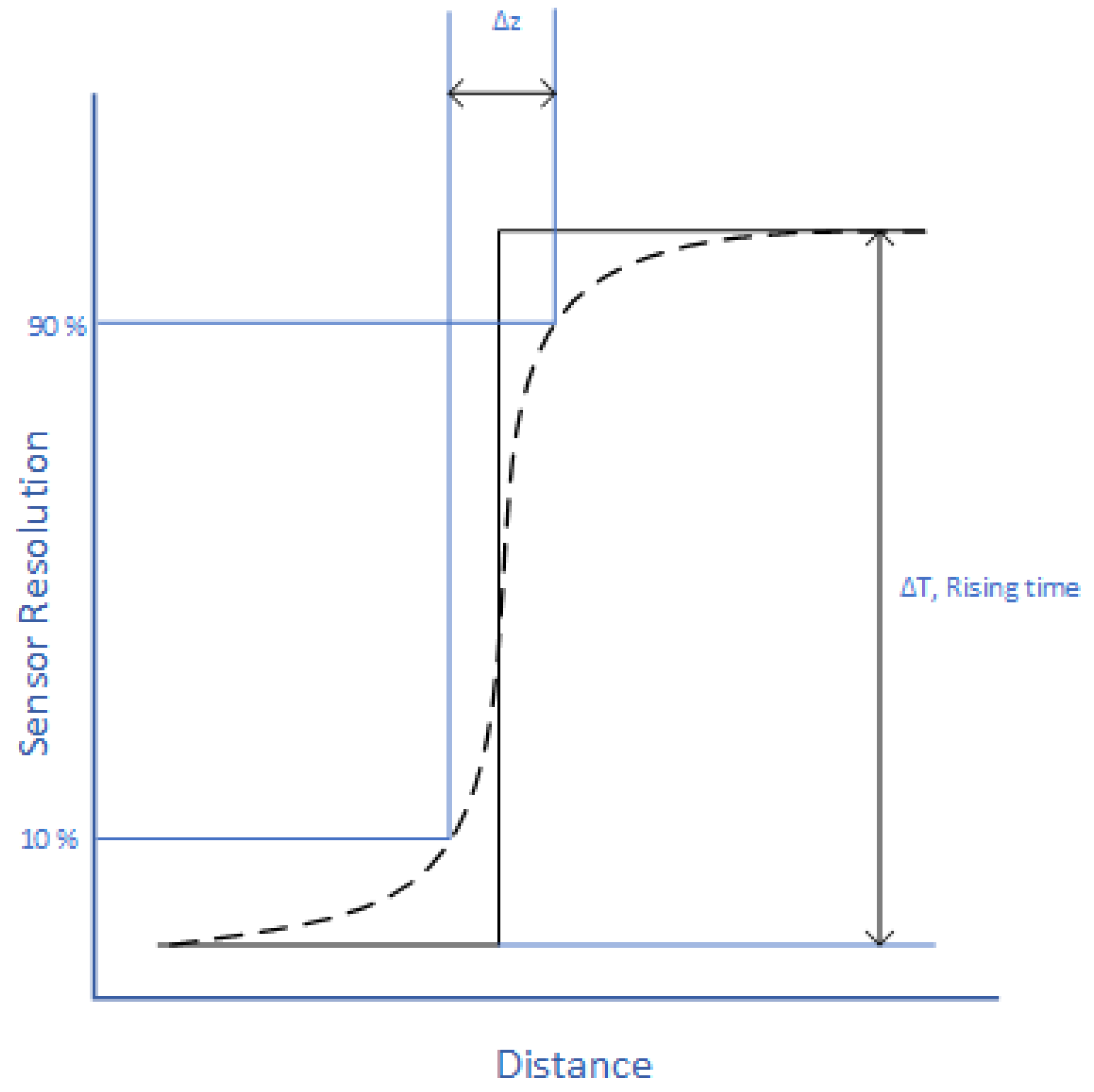
Figure 1. Sensor resolution—distance, pulse generation progress.
Photonics 10 00864 g001
Figure 2. General block diagram of FOS system.
Photonics 10 00864 g002
Figure 3. Air-resistant force approximation model applied on a fiber cable. Side (left) and front view (right).
Photonics 10 00864 g003
Figure 4. Experimental and simulated comparison for temperature sensing in FBG sensor.
Photonics 10 00864 g004
Figure 5. Experimental and simulated comparison for strain sensing in FBG sensor.
Photonics 10 00864 g005
Figure 6. The simulated sensor system in OptiSystem software.
Photonics 10 00864 g006
Figure 7. A 16-bit PN-Coding of pulse series, 56.2% of ones.
Photonics 10 00864 g007
Figure 8. Cross-correlation for single-bit pulse ((A.1): no noise, (A.2): Gaussian noise added) and 256-bit ((B.1): no noise, (B.2): Gaussian noise added) pulse sequence.
Photonics 10 00864 g008
Figure 9. Detailed, transmitted, backreflected 256-bit pulse sequence and calculated localization, with and without noise.
Photonics 10 00864 g009
Figure 10. Cross-correlation performance under Gaussian Noise for 100 km (50 km forward, 50 km backward). (A) 1-, (B) 2-, (C) 4-, (D) 8-, (E) 16-, (F) 32-, (G) 64-, (H) 128-, (I) 256-bit pulse sequence length.
Photonics 10 00864 g010
Figure 11. Localization error under high noise for different code lengths for an event 50 km away.
Photonics 10 00864 g011
Figure 12. FBG Sensor setup in OptiSystem software.
Photonics 10 00864 g012
Figure 13. FBG sensor transmitted (*.1) and reflected spectra (*.2) for different train velocities: (1) velocity of train 0 km/h (no strain), (2) 50 km/h, (3) 80 km/h.
Photonics 10 00864 g013
Figure 14. The general design of the FBG sensor system.
Photonics 10 00864 g014
Figure 15. Transmitted and received spectra for the FBG sensors system.
Photonics 10 00864 g015
Figure 16. The effect of moving the train on FBG spectra (initial states one through eight).
Photonics 10 00864 g016
Figure 17. Center frequency shifting for different air pressures for the FBG 1 backreflected signal (A: expansion air pressure, B: no air pressure, and C: compressive air pressure).
Photonics 10 00864 g017
Table 1. Train speed vs. air-resistant force values.
Tain Speed (km/h)Air Resistant Force (F(R_Air) (N))
20353
502205
805646
Table 2. Comparison summary of experimental and simulated data for temperature and strain sensing.
ParameterSet
Value
Bragg
Wavelength
(nm)
Set
Value
Bragg
Wavelength
(nm)
Experimental Temperature (Transmission) 231548.036931548.74
Simulated Temperature (Transmission) 201548.114941001549.07486
Simulated Proposed System Temperature (Transmission)231548.33931549.32
Experimental Temperature (Reflection)221548.055921548.723
Simulated Temperature (Transmission)201548.0000281001549.154909
Simulated Temperature Proposed System (Reflection)221548.21921549.131549
Experimental Strain (Reflection) 0.0011761548.620.0117651560.262
Simulated Strain (Reflection) 0.0021550.51690.0121563.291
Simulated Strain Proposed System (Reflection)0.0011761548.410.0117651562.19
Table 3. FBG sensor accuracy for temperature and strain sensing.
MeasurandAccuracy (RMSE)%
Temperature (Transmission)0.429
Temperature (Reflection)0.28
Strain (Reflection)1.39
Table 4. OptiSystem simulation environment global parameters.
NameValueUnits
Bit rate1.00 × 104bit/s
Time window0.0008s
Sample rate1.31 × 109Hz
Sequence length8bits
Samples per bit131,072
Guard Bits0
Symbol rate2000symbols/s
Number of samples1,048,576
Refractive Index1.467
Speed of Light in Space299,792m/µs
Fiber length50km
Laser Power10dBm
Laser wavelength1550nm
Table 5. Reflected signal parameters.
Train Velocity (km/h)Duration to Pass 12.5 m (s)Air Force (N)Strain Over Cable (Pa)Shifted Center Wavelength (nm)Reflected Power (dBm)
800.56564627543.33−66.2
700.64432221082.56−66.2
600.75317615491.88−66.37
500.90220510761.3−66.21
401.1314116880.84−66.38
301.507943870.46−66.35
202.253531720.21−66.38
104.5088430.05−66.16
0NA000−66.44
Table 6. FBG working frequency/wavelength.
FrequencyWavelength
GHznm
190.11577.03
191.71563.86
193.31550.92
194.91538.19
196.51525.66
Table 7. The first to sixth steps simulate the train movement over the FBGs.
IterationAir Pressure (Mpa), 1525.66 nmAir Pressure (Mpa), 1538.19 nmAir Pressure (Mpa), 1550.92 nm Air Pressure (Mpa), 1563.86 nm Air Pressure (Mpa), 1577.03 nm
10.0027540000
2−0.0027540.002754000
30−0.0027540.00275400
400−0.0027540.0027540
5000−0.0027540.002754
60000−0.002754
Table 8. Train movement effect on the PIN photodiode detection system for white light source output.
Total Power of Photodiodes
IterationPIN
1525.66 nm
PIN
1538.19 nm
PIN
1550.92 nm
PIN
1563.86 nm
PIN
1577.03 nm
1−2.2272−2.2345−2.2039−2.1348−2.1332
2−24.963−2.2364−2.2054−2.1359−2.1316
3−24.953−24.653−2.2046−2.1341−2.1335
4−2.2256−24.811−24.436−2.1267−2.1323
5−2.2276−2.2343−24.442−24.005−2.127
6−2.2288−2.2342−2.2024−24.528−24.391
7−2.2275−2.2347−2.2043−2.1364−24.417
8−2.2272−2.2345−2.2039−2.1348−2.1332
Disclaimer/Publisher’s Note: The statements, opinions and data contained in all publications are solely those of the individual author(s) and contributor(s) and not of MDPI and/or the editor(s). MDPI and/or the editor(s) disclaim responsibility for any injury to people or property resulting from any ideas, methods, instructions or products referred to in the content.