1. Introduction
Subsurface carbon storage facilities require continuous, reliable, and accurate monitoring to ensure their safe and long-term (~30 years) operation, while also minimizing their impact on the environment and local communities. Geophysical monitoring techniques deployed in the oil and gas industry provide opportunities to adapt those technologies for carbon capture and sequestration (CCS). While fiber optic distributed acoustic sensing is already having an impact in CCS monitoring, other methods such as self-potential (SP), electrical resistivity (ER), magnetotelluric (MT), and/or electromagnetic (EM) monitoring methods can be integrated with emerging technologies, such as distributed fiber optic acoustic and seismic sensing, as a near-term solution [
1,
2,
3,
4,
5,
6,
7].
There are several phenomena in carbon sequestration and other geophysical monitoring applications that can be characterized and/or monitored with the appropriate magnetic sensors. The movement of CO
2 initially pushing native brines upwards through the seal layers into the overlying permeable rock can be detected via an increase in the electrical conductivity of higher-salinity brines intruding into low-salinity brines [
3,
8]. The magnetic susceptibility can be affected by geochemical processes in carbon CCS. The detection of weak magnetic field anomalies can accompany interconnected natural fracturing, and electromagnetic mapping techniques have been shown to achieve a sharp contrast between different fluids in the downhole environment [
9,
10].
Cross-well electromagnetic imaging, in particular, consists of a transmitter deployed in one well and a receiver deployed in a second well [
11,
12,
13,
14]. A magnetically permeable core wrapped with electrically conductive wire produces a controlled sinusoidal signal. As that signal travels, electrical currents are induced in the formation, which in turn induce a secondary magnetic field related to the electrical resistivity of the rocks and fluids [
15]. The receiver is an induction coil that detects both the primary magnetic field generated by the transmitter, as well as the secondary magnetic field generated by the induced currents. In many cases, a limited number (~4–8) of receiver coils record the signal, then the process is repeated as the transmitter is traversed in a longitudinal manner in the second well. Due to the limited number of receivers, a wireline field unit and mast/crane are required at each well in order to actively position the receivers and transmitters. The resolution of cross-well EM techniques is limited by the number of receivers that can be deployed and significant data averaging. Coupled with needing to reposition the transmitter and receivers, the required time for deployment to complete the measurements is significant, and the repeatability of the time-lapse monitoring is hindered [
15].
Fluxgate magnetometers (FGMs) and nuclear magnetic resonance (NMR) sensors have been utilized in downhole applications. FGMs are often used for directional drilling and cross-well imaging [
16,
17]. An FGM is composed of two coils, an excitation and a pick-up coil, wound around a ferromagnetic rod. An alternating current (AC) is applied to the excitation coil in order to drive the ferromagnetic rod to saturation and induce a magnetic flux density in the rod. Via changes in the voltage, the pick-up coil detects the distortion of the magnetic field lines passing through upon exposure to an external magnetic field. NMR sensors provide information regarding the geological characteristics of the formations being drilled through in real time. Simply put, NMR logging tools utilize a permanent magnet and radio frequency transmitter/receiver to detect the decaying “echo” signal from those hydrogen protons that are in resonance with the field from the permanent magnet in real time. FGMs are bulky and maintain a large footprint due to the ferromagnetic cores and many windings required for operation. FGMs are not easy to calibrate and consume a large amount of power. NMR sensors only provide bulk measurements, require a non-conductive well casing, often require slow logging spreads, and are limited in terms of vertical resolution. Furthermore, FGMs and NMR are not capable of, or readily configurable for, multiplexed measurements. Although FGM and NMR sensors are “relatively affordable”, rugged, compact, and reliable, their inherent shortcomings complicate their deployment and limit the breadth of information that can be provided to operators [
16,
17,
18].
Magnetoresistive (MR), Hall effect, and giant magnetoimpedance (GMI) sensors have been proposed for use in the downhole environment in order to address the deficiencies of FGM and NMR sensors [
17]. Each have been successfully demonstrated in laboratory and industrial environments, but suffer from the electrical power requirements and susceptibility to electromagnetic interference that accompany electronic devices. Furthermore, these sensors are not easily configured for multiple spatial measurements and will ultimately require specific downhole tool designs and unique deployment procedures.
The success of optical fiber sensors in the oil and gas industry provides a template for the development of magnetic sensors that can be deployed downhole and provide operators with the information necessary to make critical decisions. Specifically, distributed acoustic sensing (DAS) has gained widespread acceptance as a reliable surveillance tool. DAS can detect, discriminate, and locate acoustic events along a single fiber length up to several kilometers [
17]. In this study, magnetic field measurements are demonstrated with a
picoDAS acoustic sensing fiber with Metglas
® 2605C wires drawn in the cladding during fiberization. The response of magnetic sensing fibers is evaluated with both one and two Metglas
® cladding wires and upon thermal magnetic annealing.
2. Materials and Methods
2.1. Magnetic Sensing Optical Fiber Fabrication
The multi-material single mode optical fiber was fabricated via a vacuum-assisted stack and draw technique. The preform was assembled and fiberized using the methods reported in [
18] for an optical fiber with nickel cladding wires. Additional processing was required in order to create Metglas
® 2605C wires with diameters on the order of 1 to 2 mm for insertion into the preform stack. The Metglas
® 2605C ribbon was cut into pieces, inserted in a fused silica glass tube, and drawn into glass-encapsulated wire. The glass encapsulation was mechanically removed, and the Metglas
® 2605C wire was inserted into a fused silica capillary tube and included in the preform stack that was fiberized on a commercial scale fiber optic draw tower with an acrylate coating [
19].
During the fiberization and draw process, as the fiber preform is exposed to the furnace and pulled, the Metglas® melts, but the glass does not. The viscosity of the glass decreases with the temperature, at which point, it can be drawn into fiber or capillary tubing. The glass acts as a crucible that is continuously drawn with the Metglas®. By carefully controlling the process by which the Metglas® pieces is filled into the tube and the draw parameters, it can be drawn into the fiber with continuous wires running through the cladding.
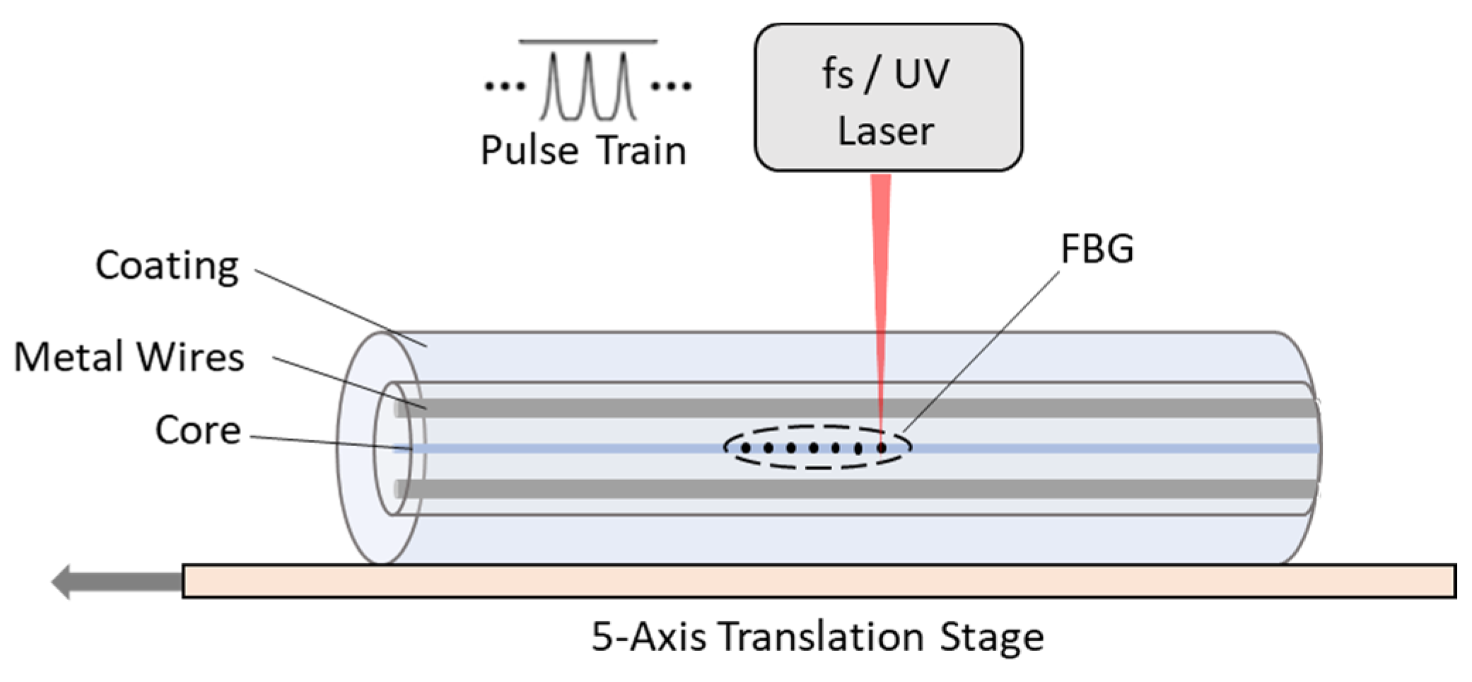
Broadband fiber Bragg gratings (FBGs) were then inscribed with a two-meter spacing between each written grating following the draw procedures, as shown schematically in
Figure 1. The fiber was positioned so that the laser has an open path to the core without being obstructed by the Metglas
® wires.
The laser used is a 780 nm infrared-femtosecond laser that then cyclically hits the fiber core, creating “damage” points. The damage points create a refractive index variation with a 900 nm grating period and are inscribed every two meters. Transmitted light (1550 nm) in the fiber will be reflected (Bragg wavelength of 529 nm) at the FBG’s working as fiber Fabry–Perot interferometers, allowing for distributed sensing with a two-meter spatial resolution.
The Metglas® inclusions in the fiber undergo strain when exposed to a magnetic field. This strain changes the optical path difference (OPD) for the light reflected from the FBG’s. The OPD is then correlated to a strain value from the system used to interrogate the fiber sensor.
2.2. Material Characterization
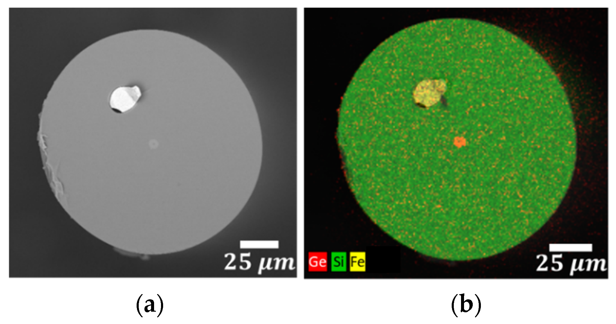
After the samples were produced, they were characterized using a scanning electron microscope (SEM, LEO 1550), taking back scatter detector images, as well as performing energy-dispersive X-ray spectroscopy (EDS) at an accelerating voltage of 20 kV. The fiber samples were prepared using a zirconia blade fiber cleaver in order to achieve a smooth cross section of the fiber. Once this was completed, the samples were coated with 10 nm of platinum and palladium coating, meaning they were sufficiently conductive to be imaged by the SEM.
As shown by the backscattered image in
Figure 2, the single Metglas
® 2605C wire is contained in the fiber cladding centered between the core and the surface of the fiber. The germanium-doped fused silica core is clearly visible in the elemental dot map in
Figure 2b, indicated by the red. The single Metglas
® wire is identified by the distinct and elevated concentration of iron (yellow) in the fused silica (silicon: green) cladding. The bare fiber is roughly 135 microns in diameter, containing an 18-micron diameter Metglas
® wire. When coated, the acrylate thickness is usually around 20 microns.
2.3. Thermal Magnetic Annealing
Metglas® 2605SC is an amorphous metal (Fe81B13.5Si3.5C2) that exhibits a magnetostrictive response upon exposure to relatively weak magnetic fields. Metglas® 2605SC has been used in a number of different configurations and types of fiber optic sensors to successfully demonstrate the detection of magnetic fields via the transduction of the strain to the fiber.
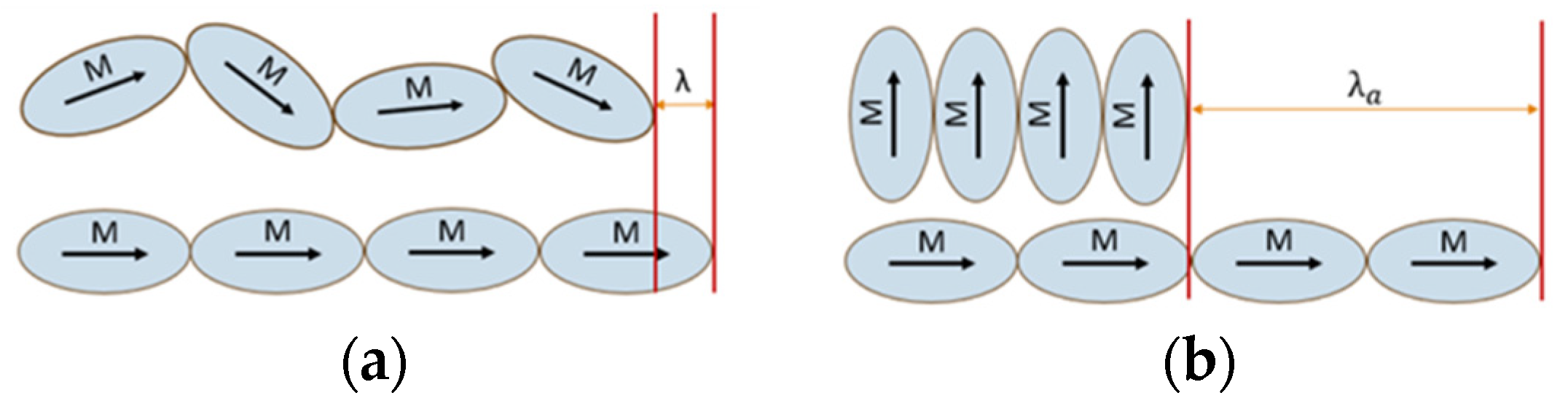
The strain response is induced by magnetic domains in the amorphous metal aligning to the external field. The maximum magnetostrictive strain response is determined by the initial positioning of the magnetic domains in the metal alloy [
19]. The magnetic domains in the Metglas
® 2605SC cladding wire(s) are randomly positioned. When an external magnetic field is applied, the domains align with the axis of the field, as shown in
Figure 3a, and elicit the strain response. For a given magnetic domain length, the change in the span between the randomly aligned domains to the axially ordered domains with the saturation magnetic field strength is λ. However, if these domains are initially positioned entirely perpendicular to the later-applied field, the effective span, λ
a, increases the maximum strain, as shown in
Figure 3b. This can be achieved by applying a DC magnetic field across the Metglas
® 2605SC, perpendicular to the intended AC magnetic field axis. However, the effect is not permanent.
The thermal magnetic annealing of a magnetostrictive alloy with an applied DC magnetic field ensures that the realignment, and improvement in the strain response, is more permanent. This is achieved via heating up the metal above the Curie temperature, all while the perpendicular field is applied. Upon cooling, the magnetic domains are “locked” in their new alignment [
20,
21].
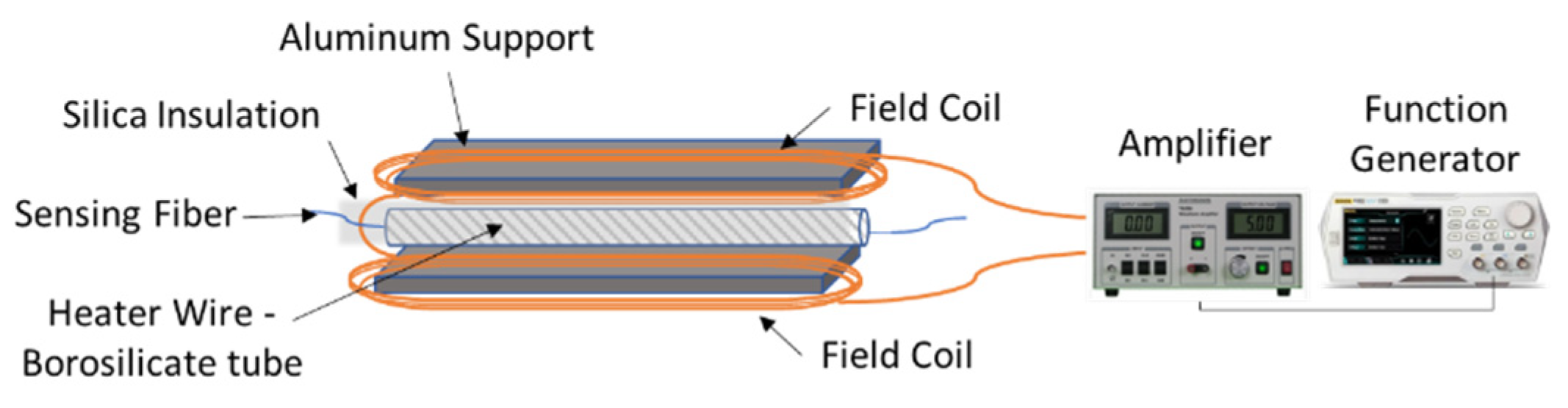
A magnetic sensing fiber with one Metglas
® 2605SC cladding wire was thermally annealed to evaluate the performance improvement. The sensing fiber (~2 m) was routed in a 19 × 25 mm borosilicate tube wrapped with a high temperature heating tape, which was positioned in the center of a Helmholtz coil, as shown in
Figure 4. The entire structure was supported by an aluminum I-beam with a length of 2.2. m and width of ~0.6 cm. A DC voltage was applied across the coil, generating a magnetic field of roughly 200 μT perpendicular to the fiber axis. A thermocouple was used to monitor the temperature inside the insulated aluminum channel, and a temperature of ~400 °C was achieved, maintained for an hour, and then cooled back to room temperature, all while the DC magnetic field was applied. The fiber acrylate coating was damaged during the heating process, meaning the fiber had to be handled carefully when being moved for testing. Helmholtz coils could be installed on opposing sides below the furnace during the draw process so that the fiber could be annealed before coating to avoid this obstacle entirely.
2.4. Optical Fiber Sensor Interrogation
The dynamic strain experienced by the sensing fiber was measured in the time domain with Sentek Instrument’s picoDAS interrogator at a sampling frequency of approximately 37 kHz. The weakly reflecting broadband FBGs inscribed in the sensing fiber are paired to form distributed Fabry–Perot interferometers that are interrogated in order to provide strain measurements with ultra-high sensitivity (<0.25 nε).
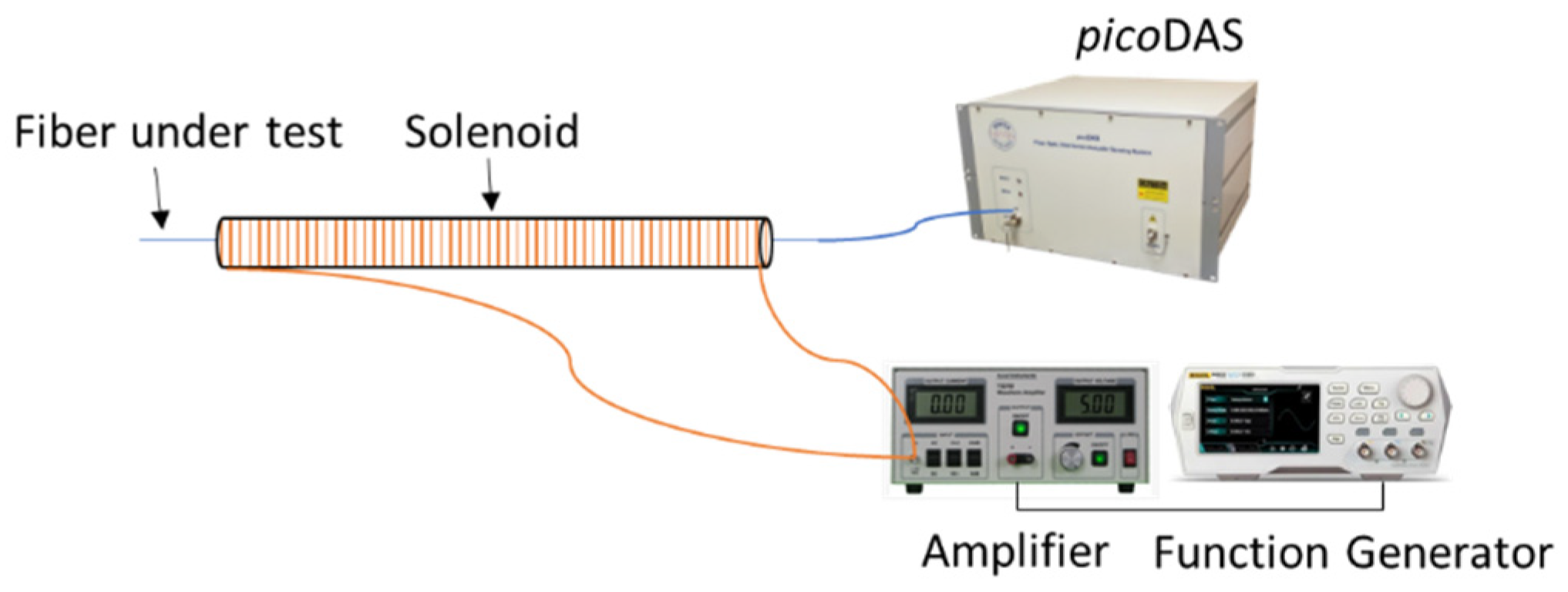
2.5. Experimental Design
The response of the sensing fibers to lateral magnetic fields was evaluated using a two-meter-long air core solenoid. The fiber was positioned so that the two inscribed FBG’s were set at each individual end of the two-meter solenoid. AC magnetic fields were generated in the solenoid with a waveform generator attached to an amplifier. A magnetic sensing probe was used to measure the AC magnetic field amplitude inside the solenoid at the same location as the fiber. The sensing fiber sample was connected to the
picoDAS interrogator, as seen in
Figure 5, to measure the dynamic strain in the time domain. This was performed using a standard single mode fiber (SMF) fusion splicer to mechanically align a connector (for the interrogation system) and the magnetic sensing fiber with a drop of optical fluid in between, ensuring transmission. The effective loss was checked and minimized using an optical time domain reflectometer (OTDR). The fast Fourier transform (FFT) of the strain data was then performed using a custom MATLAB script. The transform uses the input matrix of time, distance, and strain from the
picoDAS interrogator, generating an output of an intensity spectrum over a range of frequencies (up to 20 kHz). The sinusoidal constituent amplitudes provide the recorded intensity.
3. Results and Discussion
Three different Metglas
® multi-material fiber sensors are investigated to compare the resultant strain response from an applied sinusoidal magnetic field. The first sensor considered is shown in
Figure 2, with a single Metglas
® wire inclusion in the cladding. The second fiber sensor is the same single wire Metglas
® sample, but it has undergone thermal magnetic annealing in order to improve the strain response from the magnetostrictive wire. The third multi-material fiber sensor investigated contains two Metglas
® wire inclusions on opposite sides of the core, and, unlike the second sensor, it is not annealed. Each fiber magnetic sensor is then threaded through an air core solenoid and tested.
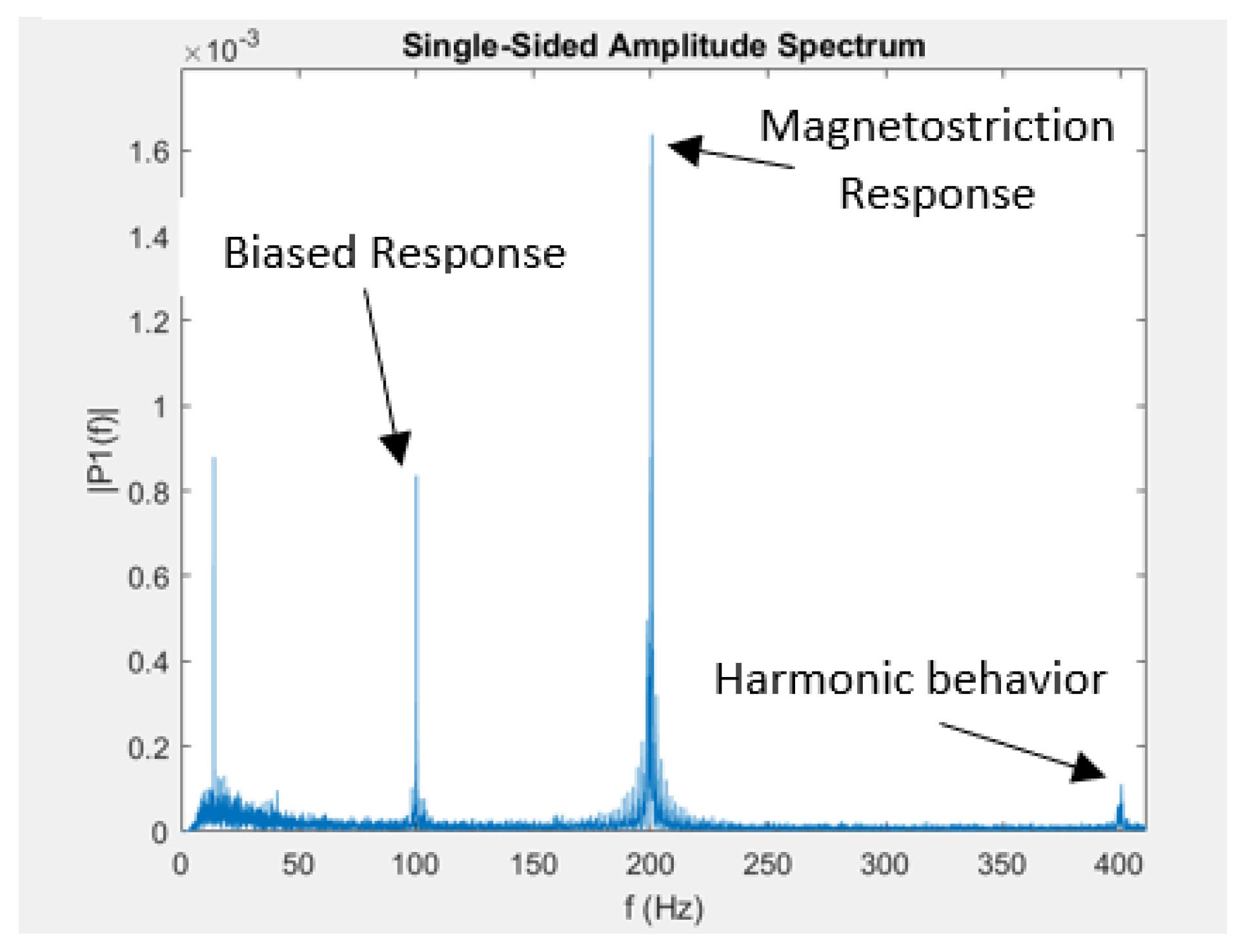
Once the multi-material fiber sensor is properly configured with the air core solenoid, a current is applied to generate the AC magnetic field amplitude, inducing a frequency response in the fiber. A sample image is provided of the intensity spectrum generated from the FFT and
picoDAS interrogator three-dimensional matrix output in
Figure 6. In the figure, three peaks are denoted.
The peak at 200 Hz indicates the magnetostrictive strain response from an 11.40 μT amplitude 100 Hz applied magnetic field. This doubling occurs because of the nature of the magnetostrictive materials. The maximum strain response in a magnetostrictive material produced from a given sinusoidal magnetic field occurs at both the minimums and maximums of the sinusoidal signal. The domain alignment along the axis and the resultant strain is effectively the same regardless of whether the field is positive or negative. The strain response will thus correlate to the magnitude of the magnetic field amplitude. This creates a frequency doubling in the strain response compared to the driving frequency of the magnetic field. However, if there is any offset to the magnetic field such that the midline of the sinusoidal wave form is greater or less than zero, the magnetostrictive strain response will begin to have a driving frequency component. This is because the minimum and maximum magnitudes of the waveform are no longer equal. If the offset pushes the minimums above zero, the strain response will then only be composed of the driving frequency.
Figure 6 shows a combination of 100 Hz and 200 Hz responses. While the generated waveform is originally unbiased, interference from ambient magnetic fields provides an offset, providing a peak response at both the driving frequency and the doubled variant. Peaks in the low frequency range (below 20 Hz) occur because of the noise from the testing environment. A smaller 400 Hz peak also occurs in
Figure 6, resulting in an acoustic harmonic from the magnetostriction vibration. The metal wire inclusions, when undergoing magnetostriction, vibrate, creating an acoustic signal. The acoustic signal will naturally result in resultant frequencies in integer multiples from the initial vibration response in the wires.
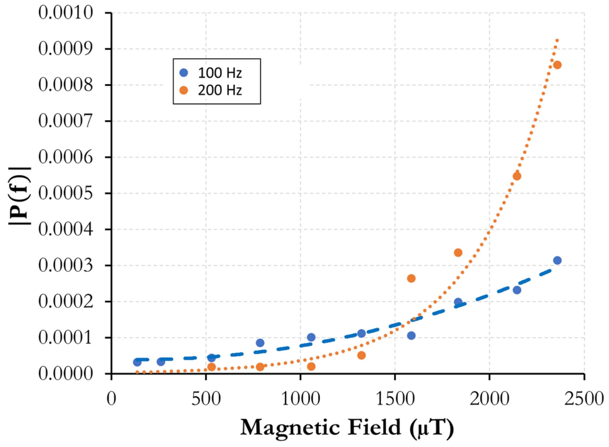
The response of the sensing fiber with one Metglas
® cladding was assessed, comparing the intensities of both the driving frequency and the doubled frequency amplitudes. The sensor response upon exposure to a 100 Hz AC magnetic field was evaluated, as shown in
Figure 7, looking at both 100 and 200 Hz, demonstrating a sensitivity of around 50 μT.
At lower fields, the driving frequency (100 Hz) was dominant, but as the AC magnetic field amplitude is increased, the largest strain response was found at double the driving frequency (200 Hz). As shown in
Figure 7, the 200 Hz curve passes the 100 Hz intensity curve at ~1250 μT. The driving frequency signal at low fields is still present, demonstrating a much smoother initial curve when compared to the doubled frequency, where the low field trend does not change much from the noise floor of the FFT signal. It is surmised that this occurs due to ambient magnetic fields or inconsistencies with the AC voltage signal generator, providing forms of bias. At low applied magnetic fields, these ambient magnetic signals can act as an offset that precludes the smaller magnetic field amplitudes from crossing the zero point. As such, the frequency of the strain response matches the driving frequency.
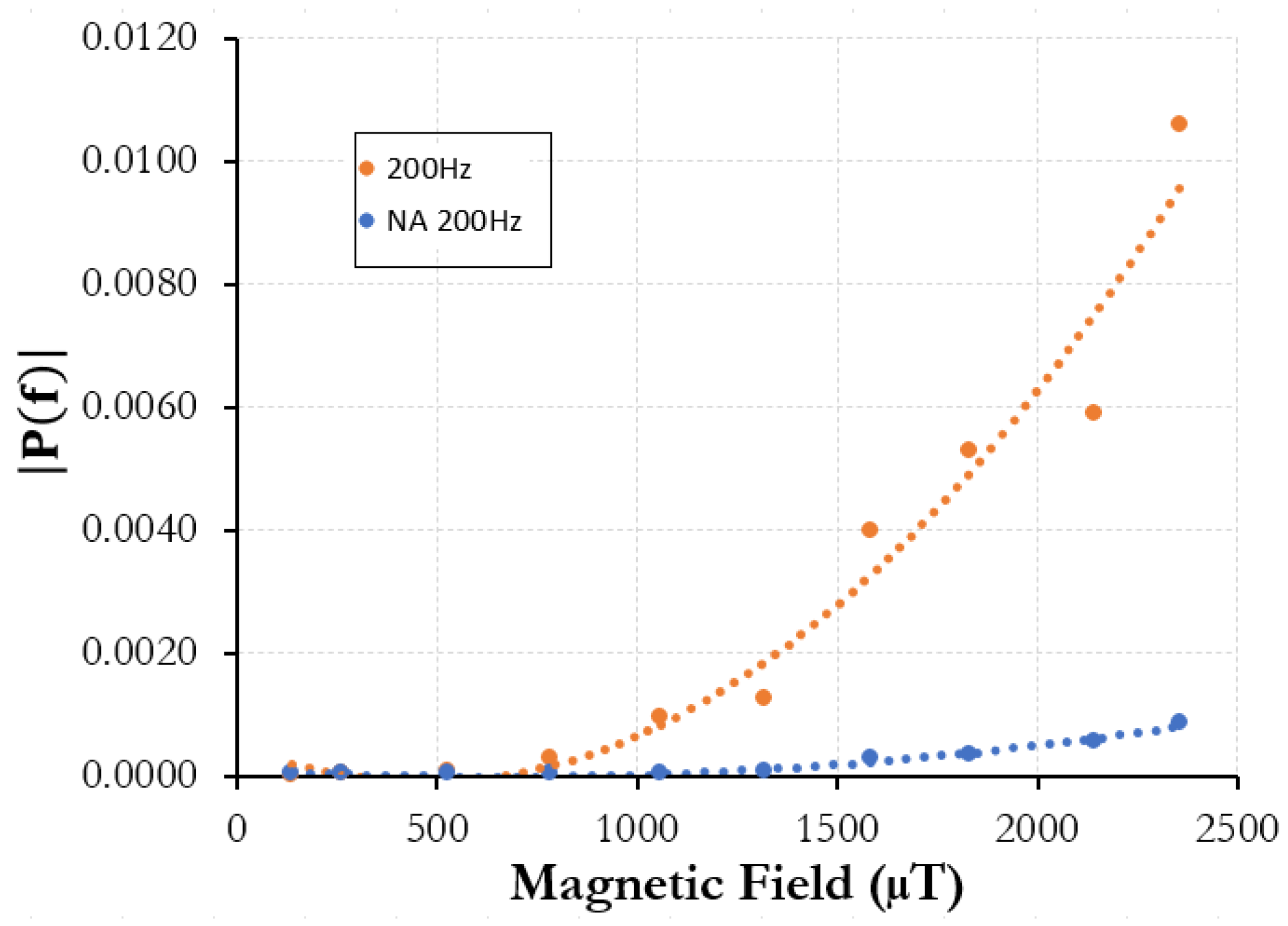
A comparison was then conducted between the multi-material single Metglas
® wire sensor and the same sensor following thermal magnetic annealing in order to investigate methods of sensor improvement. Upon magnetic annealing, the magnetic response of the same sensing fiber with the one cladding wire was evaluated upon exposure to an AC magnetic field with a 100 Hz driving frequency. As shown in
Figure 8, an improvement in the sensor response was not observed at magnetic field strengths below approximately 750 μT.
This implies that the Metglas® inside the fiber sensor is approaching the saturation of the magnetostriction. Upon increasing the AC magnetic field, the magnetic domains are allowed to move with a larger range of motion and, in turn, create a stronger signal. At the largest field measured (2358 μT), the strain response FFT intensity was almost an order of magnitude greater than that of the sample before annealing. Thus, magnetic annealing can be performed to increase the relative magnetic sensing resolution for the fiber sensor at higher field strengths, as compared to the pristine condition.
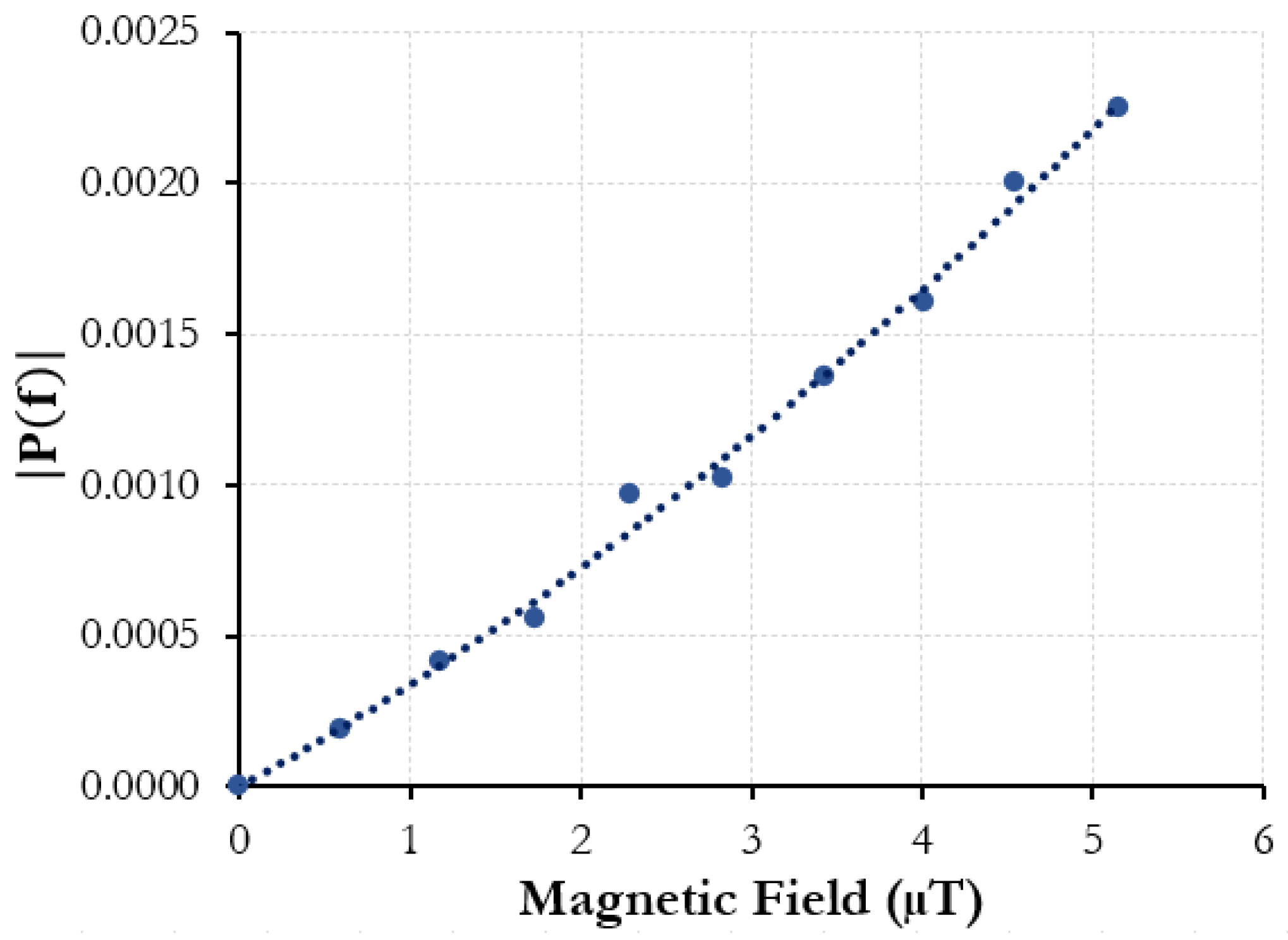
The magnetic response of a sensing fiber with two Metglas
® cladding wires was tested to evaluate the effect of adding more magnetostrictive material in the fiber cladding. The addition of a second Metglas
® cladding wire yielded a significant improvement in sensor response upon exposure to weaker AC magnetic fields with a 100 Hz driving frequency. As shown in
Figure 9, the minimum detectable fields were two orders of magnitude smaller than that observed for the single cladding wire sample. As anticipated, the dynamic strain was only observed at the driving frequency due to the small applied magnetic field amplitude. A minimum detectable magnetic field strength of ~500 nT was demonstrated, as compared to ~50 μT for the single cladding wire sample. The increase in the volume of the magnetostrictive material in the fiber cladding resulted in a greater strain transfer to the fiber and, in turn, better sensitivity.
The multi-material fiber sensor samples were evaluated at a variety of frequencies, showing consistent responses. However, the magnetometer used to measure the magnetic field in the solenoid was frequency dependent, and, for the sake of conciseness and clarity, only a 100 Hz driving frequency was investigated. The strain response from the Metglas® across all three sensor variants displayed a consistent positive relation to magnetic field amplitude at 100 Hz. However, there is some deviation in the response curve. This error could originate from multiple variables, including improper strain transfer from the Metglas® to the fiber, inconsistencies in the draw process (temperature influence on the metal, wire inclusion variation, etc.), or alignment inside the solenoid itself. More investigation needs to be completed in order to better characterize the Metglas® multi-material fiber sensors and address the variability. Added repeated tests will demonstrate consistency and statistical significance. However, for an initial demonstration of the technology and experimental results, the relationship between the strain response in the fiber and the magnetic field amplitude shows promise moving forward.
The strain measurements taken in the study are derived from the OPD. The OPD is affected by anything that changes the refractive index in the fiber or physically alters the path distance. This can come from strain, mechanical bending, and temperature. The fiber position and temperature are maintained in this study when analyzing the strain response from an applied AC magnetic field. This isolates the OPD changes to only those derived from the magnetostriction of the cladding wires in the fiber, as well as external noise from the environment (acoustic vibration). Changes in temperature during testing would change the measured strain output from the multi-material fiber sensor as the refractive index changes. However, this was not tested within the scope of this research. In future work, a strictly acoustic sensor FBG fiber could be paired in tandem with the magnetic sensing multi-material fiber. Changes in temperature will impact the OPD similarly in both fibers, and could be subtracted out to help remove temperature-induced changes in magnetic sensing. The long term use of the fiber sensor should also be looked at moving forward, and since the magnet response can also change with temperature or could degrade over time, periodic calibrations may be needed to ensure consistency as an effective magnetic field sensor. This is the case with widely used magnetometers as well.
4. Conclusions
In this paper, three different multi-material optical fiber magnetic sensors were developed and evaluated. While multi-material magnetic sensing fibers have been successfully demonstrated via inclusions such as nickel, this is the first time where the engineered alloy Metglas
® was used. Nickel-based fiber sensors were able to measure fields on the order of hundreds of μT from the literature [
18]. However, with the Metglas
® two wire sample, the resolution could effectively detect AC magnetic field amplitudes as low as 500 nano-Tesla, improving upon the single wire Metglas
® fibers at a sensitivity around 50 μT. Annealing was also shown to improve the resolution for higher magnetic fields. With the exact same single wire inclusion fiber sample (first tested normally, and then following thermal magnetic annealing), a strain response improvement was shown to be almost an order of magnitude for the intensity amplitude strain response at magnetic field amplitudes above 2000 μT. Moving forward, further analysis and testing needs to be completed in order to potentially investigate better resolution and sensitivity. Annealing more samples, enlarging the Metglas
® wires in the fiber sample, using different materials in the sensor, or using magnetostrictive materials in conjunction with standard acoustic sensing fibers could all be methods to achieve better results. The robust easy-to-manufacture nature of optical fibers, along with the distributed sensing capabilities and nano-tesla level sensitivity of the Metglas
® multi-material fiber sensor, demonstrate strong potential for commercial use in the oil and energy industries, or even in biomedical applications if better sensing resolutions are achieved.

 ,
, 


