Switchable Dual-Wavelength Thulium-Doped Fiber Laser Based on Polarization-Maintaining Fiber Bragg Grating and Compound Cavity Filter

 and
and
Abstract
1. Introduction
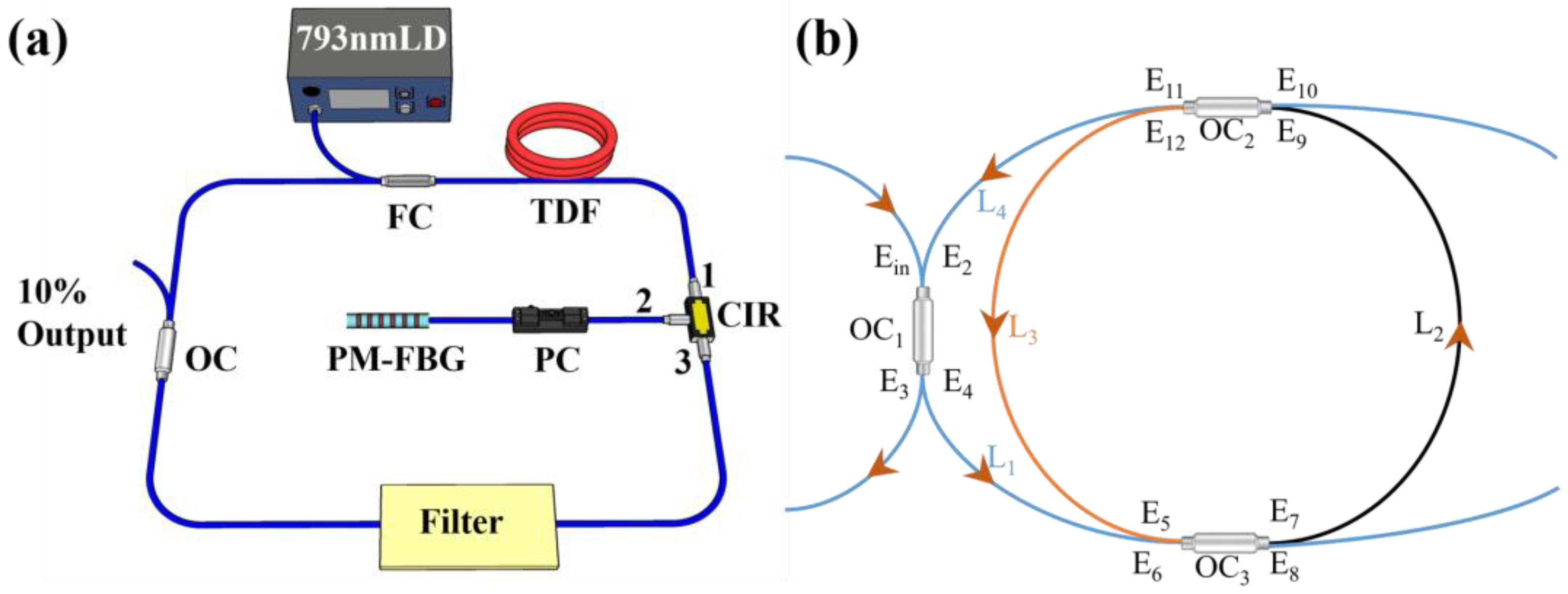
2. Experimental Instrument and Principles
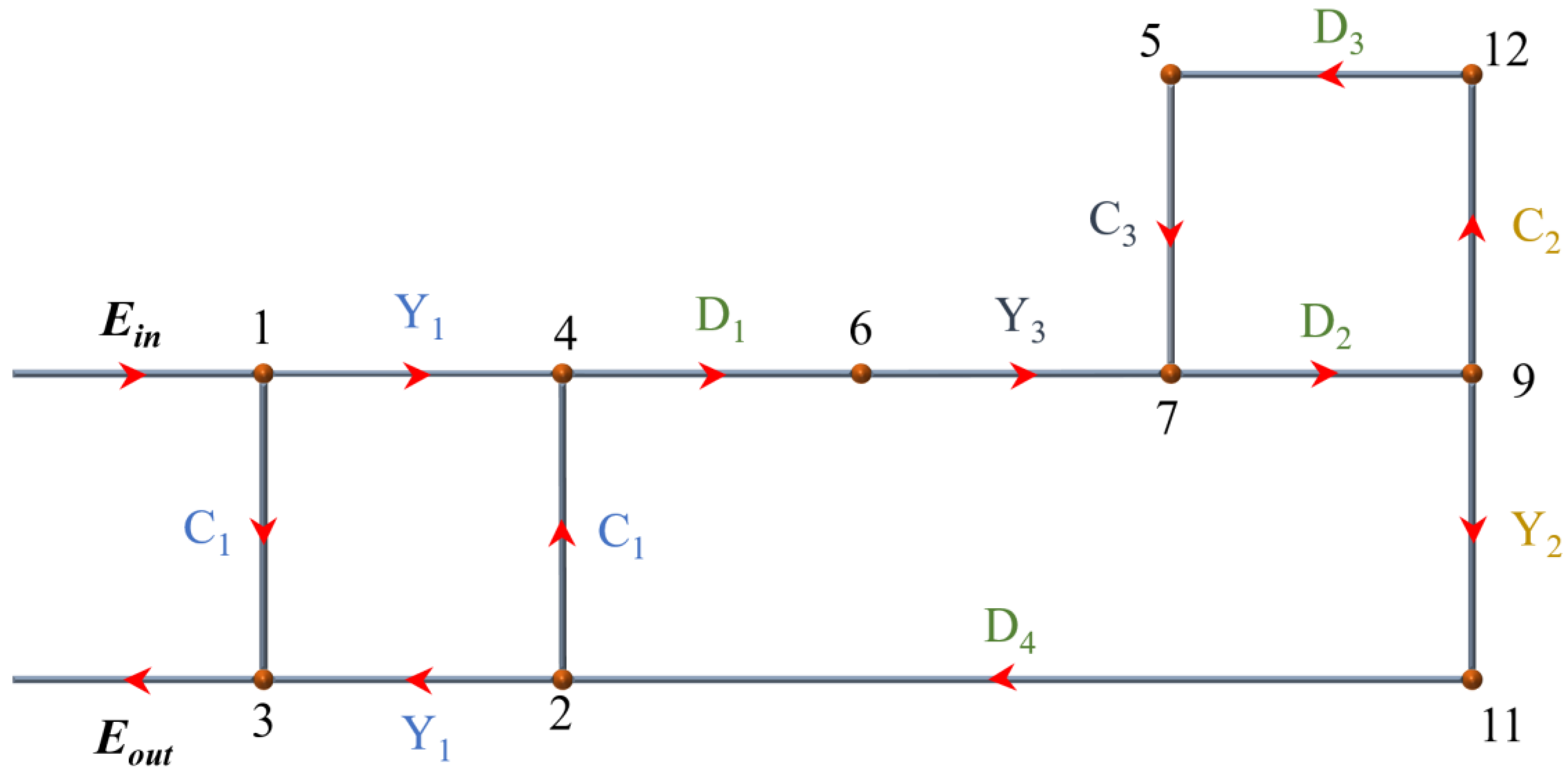
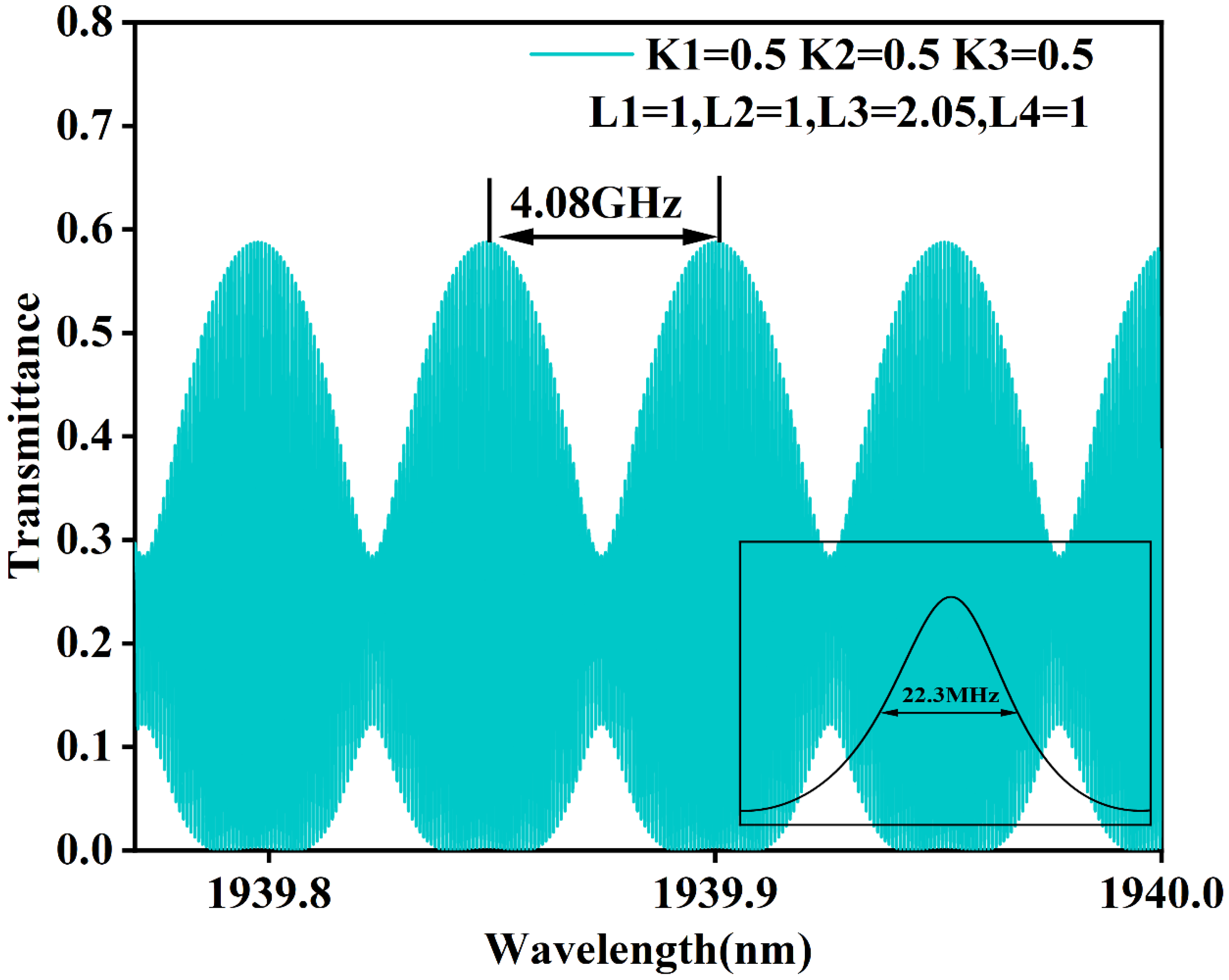
3. SLM of Principle
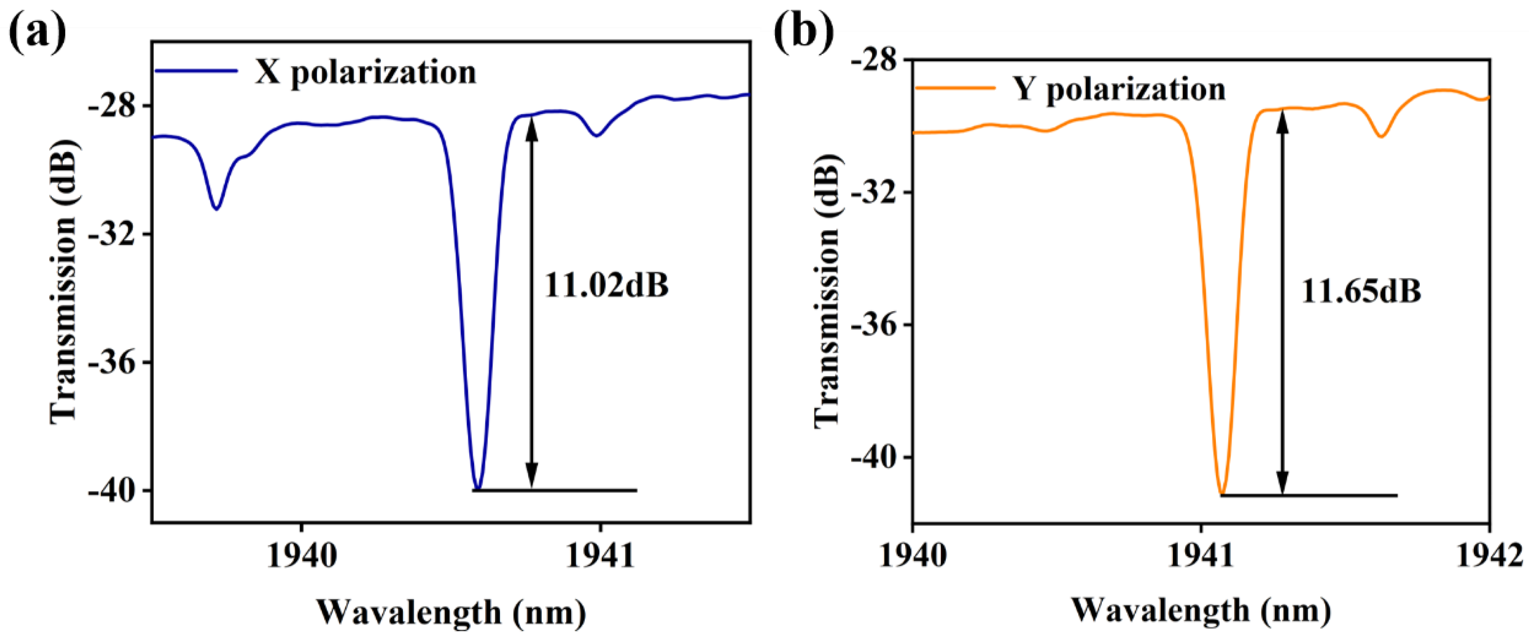
4. Experimental Results and Discussion
5. Conclusions
Author Contributions
Funding
Institutional Review Board Statement
Informed Consent Statement
Data Availability Statement
Conflicts of Interest
References
- Ter-Mikirtychev, V. Fundamentals of Fiber Lasers and Fiber Amplifiers; Springer: Berlin/Heidelberg, Germany, 2014; Volume 99. [Google Scholar]
- Jackson, S.D.; King, T.A. Theoretical modeling of Tm-doped silica fiber lasers. J. Light. Technol. 1999, 17, 948. [Google Scholar] [CrossRef]
- Moulton, P.F.; Rines, G.A.; Slobodtchikov, E.V.; Wall, K.F.; Frith, G.; Samson, B.; Carter, A.L. Tm-doped fiber lasers: Fundamentals and power scaling. IEEE J. Sel. Top. Quantum Electron. 2009, 15, 85–92. [Google Scholar] [CrossRef]
- Qin, Q.; Li, T.; Yan, F.; Feng, T.; Sun, W.; Han, W.; Yang, D.; Wang, X.; Yu, C.; Wang, P. Demonstration of the first outdoor 2-μm-band real-time video transmission free-space optical communication system using a self-designed single-frequency fiber laser. J. Light. Technol. 2023, 41, 5275–5283. [Google Scholar] [CrossRef]
- Huang, C.; Tang, Y.; Li, H.; Wang, Y.; Xu, J.; Du, C. A versatile model for temperature-dependent effects in Tm-doped silica fiber lasers. J. Light. Technol. 2013, 32, 421–428. [Google Scholar] [CrossRef]
- Kieleck, C.; Berrou, A.; Donelan, B.; Cadier, B.; Robin, T.; Eichhorn, M. 6.5 W ZnGeP 2 OPO directly pumped by a Q-switched Tm 3+-doped single-oscillator fiber laser. Opt. Lett. 2015, 40, 1101–1104. [Google Scholar] [CrossRef] [PubMed]
- Roesner, A.; Abels, P.; Olowinsky, A.; Matsuo, N.; Hino, A. Absorber-free laser beam welding of transparent thermoplastics. In Proceedings of the International Congress on Applications of Lasers & Electro-Optics, Temecula CA, USA, 20–23 October 2008. [Google Scholar]
- Mingareev, I.; Weirauch, F.; Olowinsky, A.; Shah, L.; Kadwani, P.; Richardson, M. Welding of polymers using a 2 μm thulium fiber laser. Opt. Laser Technol. 2012, 44, 2095–2099. [Google Scholar] [CrossRef]
- McComb, T.S.; Sims, R.A.; Willis, C.C.; Kadwani, P.; Shah, L.; Richardson, M. Atmospheric transmission testing using a portable, tunable, high power thulium fiber laser system. In Conference on Lasers and Electro-Optics; Optica Publishing Group: Washington, DC, USA, 2010; p. JThJ5. [Google Scholar]
- Xylinas, E.; Rink, M.; Cha, E.K.; Clozel, T.; Lee, R.K.; Fajkovic, H.; Comploj, E.; Novara, G.; Margulis, V.; Raman, J.D. Impact of distal ureter management on oncologic outcomes following radical nephroureterectomy for upper tract urothelial carcinoma. Eur. Urol. 2014, 65, 210–217. [Google Scholar] [CrossRef] [PubMed]
- Zhang, J.; Ou, Z.; Zhang, X.; He, W.; Wang, R.; Mo, M.; Chen, L.; Xu, R.; Jiang, S.; Peng, X. Holmium laser enucleation of the prostate versus thulium laser enucleation of the prostate for the treatment of large-volume prostates> 80 ml: 18-month follow-up results. World J. Urol. 2020, 38, 1555–1562. [Google Scholar] [CrossRef] [PubMed]
- Janeczek, M.; Świderski, J.; Czerski, A.; Żywicka, B.; Bujok, J.; Szymonowicz, M.; Bilewicz, E.; Dobrzyński, M.; Korczyński, M.; Chrószcz, A. Preliminary evaluation of thulium doped fiber laser in pig model of liver surgery. BioMed Res. Int. 2018, 2018, 3275284. [Google Scholar] [CrossRef]
- Becker, B.; Enikeev, D.; Netsch, C.; Gross, A.J.; Laukhtina, E.; Glybochko, P.; Rapoport, L.; Herrmann, T.R.; Taratkin, M. Comparative analysis of vaporization and coagulation properties of a hybrid laser (combination of a thulium and blue diode laser) vs thulium and Ho: YAG lasers: Potential applications in endoscopic enucleation of the prostate. J. Endourol. 2020, 34, 862–867. [Google Scholar] [CrossRef]
- Wen, J.; Ji, Z.G.; Li, H.Z. Treatment of upper tract urothelial carcinoma with ureteroscopy and thulium laser: A retrospective single center study. BMC Cancer 2018, 18, 196. [Google Scholar] [CrossRef] [PubMed]
- Sciarra, A.; Von Heland, M.; Minisola, F.; Salciccia, S.; Cattarino, S.; Gentile, V. Thulium laser supported nephron sparing surgery for renal cell carcinoma. J. Urol. 2013, 190, 698–701. [Google Scholar] [CrossRef] [PubMed]
- Glybochko, P.; Alyaev, Y.; Rapoport, L.; Enikeev, D.; Enikeev, M.; Sorokin, N.; Sukhanov, R.; Dymov, A.; Taratkin, M. PDD-guided thulium fiber laser en-bloc enucleation of bladder tumor. Eur. Urol. Suppl. 2018, 17, e1967. [Google Scholar] [CrossRef]
- Chiron*, P.; Berthe, L.; Haddad, M.; Doizi, S.; Traxer, O. PD59-06 in vitro comparison of efficiency between superpulsed thulium fiber laser and HO: YAG laser for endocorporeal lithotripsy. J. Urol. 2019, 201, e1093. [Google Scholar] [CrossRef]
- Enikeev, D.; Traxer, O.; Taratkin, M.; Okhunov, Z.; Shariat, S. A review of thulium-fiber laser in stone lithotripsy and soft tissue surgery. Curr. Opin. Urol. 2020, 30, 853–860. [Google Scholar] [CrossRef]
- Voo, N.; Sahu, J.; Ibsen, M. 345-mW 1836-nm single-frequency DFB fiber laser MOPA. IEEE Photonics Technol. Lett. 2005, 17, 2550–2552. [Google Scholar] [CrossRef]
- Guan, X.; Yang, C.; Qiao, T.; Lin, W.; Zhao, Q.; Tang, G.; Qian, G.; Qian, Q.; Yang, Z.; Xu, S. High-efficiency sub-watt in-band-pumped single-frequency DBR Tm 3+-doped germanate fiber laser at 1950 nm. Opt. Express 2018, 26, 6817–6825. [Google Scholar] [CrossRef]
- Chen, X.; Deng, Z.; Yao, J. Photonic generation of microwave signal using a dual-wavelength single-longitudinal-mode fiber ring laser. IEEE Trans. Microw. Theory Tech. 2006, 54, 804–809. [Google Scholar] [CrossRef]
- Li, Y.; Huang, L.; Gao, L.; Lan, T.; Cao, Y.; Ikechukwu, I.P.; Shi, L.; Liu, Y.; Li, F.; Zhu, T. Optically controlled tunable ultra-narrow linewidth fiber laser with Rayleigh backscattering and saturable absorption ring. Opt. Express 2018, 26, 26896–26906. [Google Scholar] [CrossRef]
- An, H.; Lin, X.; Pun, E.; Liu, H. Multi-wavelength operation of an erbium-doped fiber ring laser using a dual-pass Mach–Zehnder comb filter. Opt. Commun. 1999, 169, 159–165. [Google Scholar] [CrossRef]
- Lee, Y.W.; Lee, B. Wavelength-switchable erbium-doped fiber ring laser using spectral polarization-dependent loss element. IEEE Photonics Technol. Lett. 2003, 15, 795–797. [Google Scholar]
- Zhang, Z.; Zhan, L.; Xu, K.; Wu, J.; Xia, Y.; Lin, J. Multiwavelength fiber laser with fine adjustment, based on nonlinear polarization rotation and birefringence fiber filter. Opt. Lett. 2008, 33, 324–326. [Google Scholar] [CrossRef] [PubMed]
- Feng, S.; Xu, O.; Lu, S.; Mao, X.; Ning, T.; Jian, S. Switchable dual-wavelength erbium-doped fiber-ring laser based on one polarization maintaining fiber Bragg grating in a Sagnac loop interferometer. Opt. Laser Technol. 2009, 41, 264–267. [Google Scholar] [CrossRef]
- Feng, S.; Xu, O.; Lu, S.; Ning, T.; Jian, S. Switchable multi-wavelength erbium-doped fiber ring laser based on cascaded polarization maintaining fiber Bragg gratings in a Sagnac loop interferometer. Opt. Commun. 2008, 281, 6006–6010. [Google Scholar] [CrossRef]
- Mason, S.J. Feedback theory-some properties of signal flow graphs. Proc. IRE 1953, 41, 1144–1156. [Google Scholar] [CrossRef]
- Feng, T.; Wei, D.; Bi, W.; Sun, W.; Wu, S.; Jiang, M.; Yan, F.; Suo, Y.; Yao, X.S. Wavelength-switchable ultra-narrow linewidth fiber laser enabled by a figure-8 compound-ring-cavity filter and a polarization-managed four-channel filter. Opt. Express 2021, 29, 31179–31200. [Google Scholar] [CrossRef]
- Bai, Y.; Yan, F.; Feng, T.; Han, W.; Zhang, L.; Cheng, D.; Bai, Z.; Wen, X. Demonstration of linewidth measurement based on phase noise analysis for a single frequency fiber laser in the 2 μm band. Laser Phys. 2019, 29, 075102. [Google Scholar] [CrossRef]


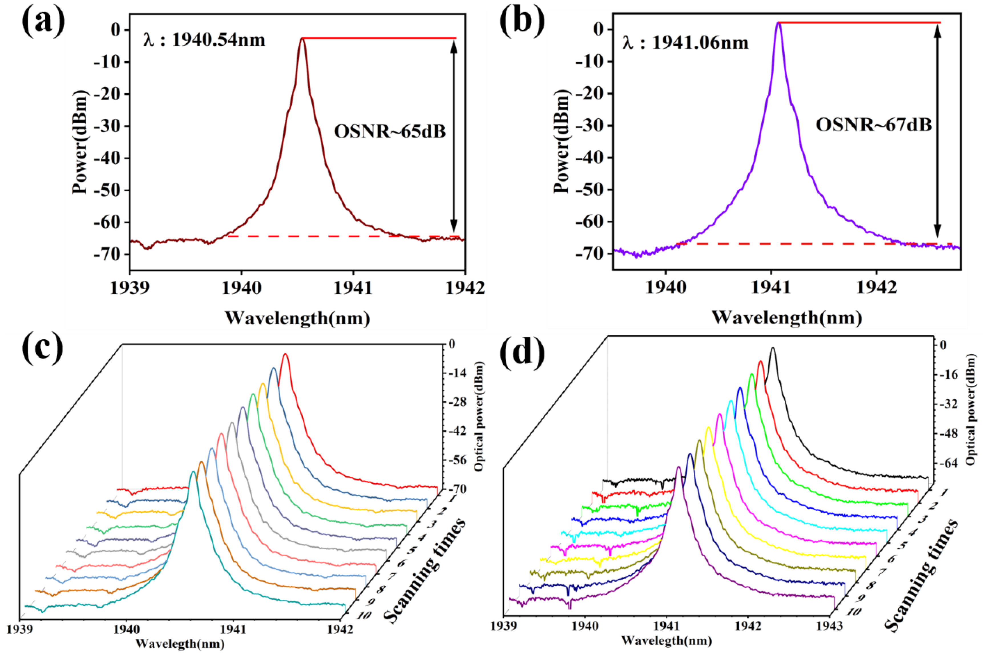
| Wavelength (nm) | Wavelength Drift (nm) | Power Fluctuations (dB) |
|---|---|---|
| 1940.54 | 0.03 | 0.8 |
| 1941.06 | 0.02 | 1.3 |
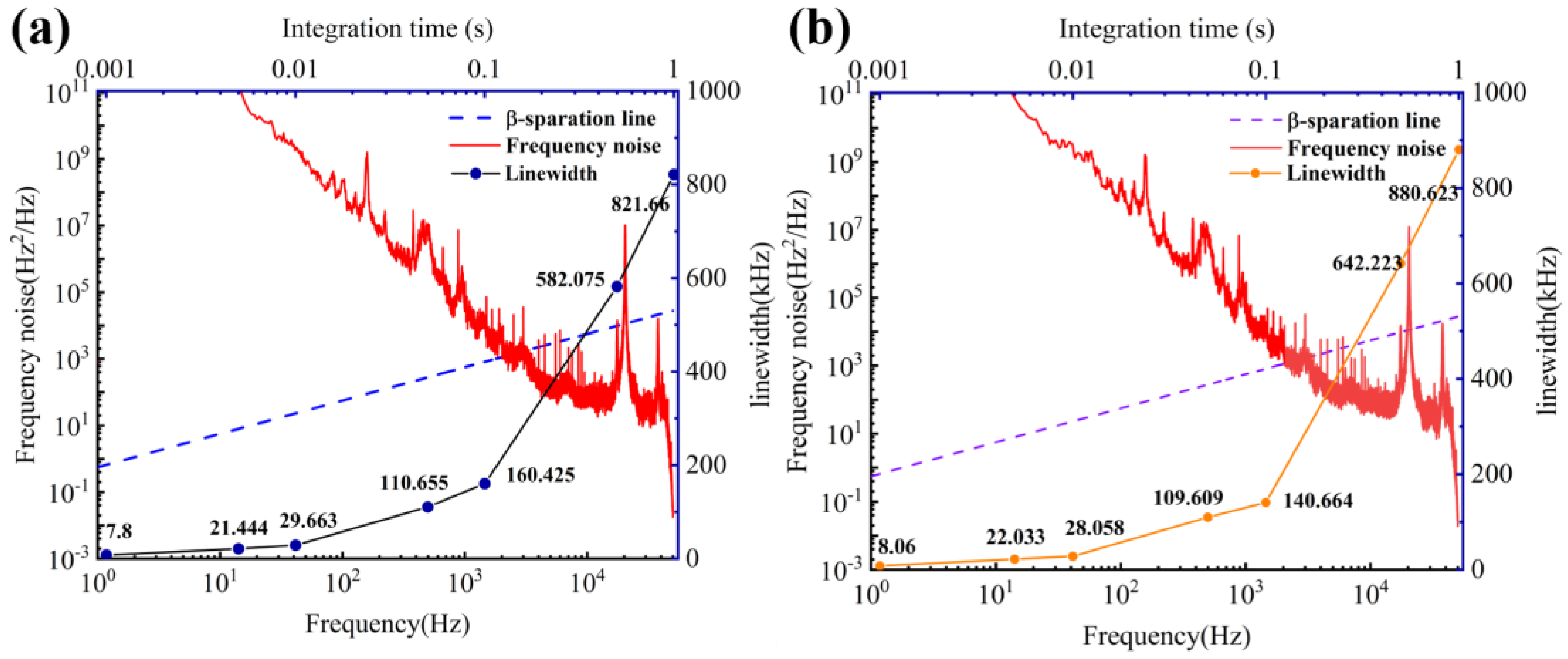
| T (s) | 0.001 | 0.005 | 0.01 | 0.1 | 1 |
|---|---|---|---|---|---|
| Linewidth at the wavelength 1940.54 nm (kHz) | 7.8 | 21.444 | 28.663 | 160.425 | 821.663 |
| Linewidth at the wavelength 1941.06 nm (kHz) | 8.06 | 22.033 | 28.058 | 140.664 | 880.623 |
Disclaimer/Publisher’s Note: The statements, opinions and data contained in all publications are solely those of the individual author(s) and contributor(s) and not of MDPI and/or the editor(s). MDPI and/or the editor(s) disclaim responsibility for any injury to people or property resulting from any ideas, methods, instructions or products referred to in the content. |
© 2024 by the authors. Licensee MDPI, Basel, Switzerland. This article is an open access article distributed under the terms and conditions of the Creative Commons Attribution (CC BY) license (https://creativecommons.org/licenses/by/4.0/).
Share and Cite
Wang, X.; Yan, F.; Guo, H.; Wang, W.; Yang, D.; Wang, P.; Li, T.; Yu, C.; Kumamoto, K.; Suo, Y. Switchable Dual-Wavelength Thulium-Doped Fiber Laser Based on Polarization-Maintaining Fiber Bragg Grating and Compound Cavity Filter. Photonics 2024, 11, 360. https://doi.org/10.3390/photonics11040360
Wang X, Yan F, Guo H, Wang W, Yang D, Wang P, Li T, Yu C, Kumamoto K, Suo Y. Switchable Dual-Wavelength Thulium-Doped Fiber Laser Based on Polarization-Maintaining Fiber Bragg Grating and Compound Cavity Filter. Photonics. 2024; 11(4):360. https://doi.org/10.3390/photonics11040360
Chicago/Turabian StyleWang, Xiangdong, Fengping Yan, Hao Guo, Wei Wang, Dandan Yang, Pengfei Wang, Ting Li, Chenhao Yu, Kazuo Kumamoto, and Yuping Suo. 2024. "Switchable Dual-Wavelength Thulium-Doped Fiber Laser Based on Polarization-Maintaining Fiber Bragg Grating and Compound Cavity Filter" Photonics 11, no. 4: 360. https://doi.org/10.3390/photonics11040360
APA StyleWang, X., Yan, F., Guo, H., Wang, W., Yang, D., Wang, P., Li, T., Yu, C., Kumamoto, K., & Suo, Y. (2024). Switchable Dual-Wavelength Thulium-Doped Fiber Laser Based on Polarization-Maintaining Fiber Bragg Grating and Compound Cavity Filter. Photonics, 11(4), 360. https://doi.org/10.3390/photonics11040360