Article

A Near Fourier-Limited Pulse-Preserving Monochromator for Extreme-Ultraviolet Pulses in the Few-Fs Regime

1
Center for Free Electron Laser Science CFEL, Deutsches Elektronen-Synchrotron DESY, Notkestraße 85, 22607 Hamburg, Germany
2
The Hamburg Centre for Ultrafast Imaging, Luruper Chaussee 149, 22761 Hamburg, Germany
3
Songshan Lake Materials Laboratory, Dongguan 523808, China
4
Institute for Experimental Physics, University of Hamburg and Center for Free Electron Laser Science CFEL, Luruper Chaussee 149, 22761 Hamburg, Germany
5
Fraunhofer IOF, Albert-Einstein-Straße 7, 07745 Jena, Germany
6
Department of Applied Sciences and Health, Coburg University of Applied Sciences and Arts, Friedrich-Streib-Straße 2, 96450 Coburg, Germany
7
Institute for Sensor and Actuator Technology ISAT, Am Hofbräuhaus 1b, 96450 Coburg, Germany
*
Author to whom correspondence should be addressed.
Photonics 2024, 11(6), 525; https://doi.org/10.3390/photonics11060525
Submission received: 26 March 2024 / Revised: 22 May 2024 / Accepted: 28 May 2024 / Published: 1 June 2024

Abstract

:
We present a pulse-preserving multilayer-based extreme-ultraviolet (XUV) monochromator providing ultra-narrow bandwidth ( Δ E < 0.6 eV , E c = 92 eV ) and compact footprint ( 28 × 10 cm 2 ) for easy integration into high-harmonic generation (HHG) or free-electron laser (FEL) sources. The temporal resolution of the novel design supports pulse durations of typical pump–probe setups in the femtosecond and attosecond regime, depending on the mirror design and focusing geometries over the tuning range of the monochromator. The theoretical design is analyzed and experimentally characterized in a laser-driven HHG setup.

1. Introduction

The availability of ultrashort and even few-cycle laser pulses has enabled high-harmonic generation (HHG) to serve as a source of ultrashort light pulses with photon energies up to the ‘water window’ region (282–533 eV) [1,2,3]. Using multilayer mirrors as band-pass filters is a standard technique for generating even shorter pulses down to 43 attoseconds (as) [4,5,6,7,8]. Spectroscopic analyses have benefited greatly from this development. Furthermore, most experiments do not require ultimate time resolution but rather a tunable, narrow bandwidth to match experimental needs. Grating monochromators are commonly used to adjust bandwidth and carrier wavelength. For ultrafast pump–probe spectroscopy in the XUV spectral range, grating monochromators have been fine-tuned to support the well-defined requirements and minimized dispersion properties [9,10,11]. However, they lead to significant temporal broadening of the pulse due to dispersion if no further action is taken, and even then the achievable pulsewidth is limited by these techniques.
Although good monochromatization and high transmission have benefits, they usually introduce temporal distortions. Additionally, the output pulses do not align with the input beam, necessitating separate paths for XUV and NIR pulses, which require active vibration stabilization schemes for a pump–probe setup. To maintain the temporal characteristics of a high-harmonic-generated XUV pulse, a multilayer mirror monochromator is a preferable setup that allows for collinear propagation and enables the easy control of dispersion properties through design [5,12,13,14]. A disadvantage of a typical multilayer mirror monochromator is the relatively small tuning range, comparably low reflectivity and resulting monochromator throughput [15]. Here, we demonstrate that the easy integration and compact footprint provides an ideal platform for existing setups to gain tunability and monochromatization with superior pulse properties and low dispersion to preserve pulse durations down into the attosecond regime. In contrast to the even smaller bandwidth achieved in HHG multilayer monachromatization for long driving pulses and in the low-order harmonic wavelength regime recently demonstrated by Guo et al. [16], the goal of the setup under investigation is the highest time resolution only limited by the reflective bandwidth of the multilayer mirrors but still resolving spin components in photoelectron spectroscopy. The initial results of these developments are presented in [17].
In typical designs, the temporal shape of the reflected pulse is often calculated based on the time–bandwidth product (TBP) of the monochromator characteristics. However, for HHG sources, the finite source distance leads to natural beam divergence, requiring basic design considerations to account for it. To maintain a nearly Fourier-limited pulse duration, a focusing mirror is typically required as part of the setup. Within the Rayleigh range, the temporal shape is preserved. Thus, the pulse duration is mainly determined by the spectral amplitude and phase. The reflectivity and phase of the multilayer coating and the HHG spectrum determine the duration in this case. Hence, an experimental setup must provide a focus at the sample position to fulfill this basic requirement.
On the other hand, achieving tunability requires an angular change resulting in an angular shift of the focus position. To account for the angular and spectral shift, a second mirror in a Z-shaped geometry adjusts the distance and angle between the two mirrors. Furthermore, correcting for a focus shift along the optical axis is achieved by moving both mirrors simultaneously along the propagation direction. Accounting for these degrees of freedom, a multilayer monochromator setup can provide a fixed focus position over the total angular tuning range.
In this study, we explore the properties of a Z-shaped, ultra-narrow bandwidth multilayer monochromator. Specifically, we examine its reflected peak photon energy and bandwidth, which determine the Fourier-limited pulse duration, as well as the pulse front distortion at realistic distances from the high-harmonic generation source, based on our experimental geometry.

2. Theory of Multilayer Mirrors

The fundamental working principle of a multilayer mirror involves the interference of light that reflects from the interfaces of two alternating thin layers of materials having high and low refractive indices [18,19]. Such reflection causes partial transmissions and reflections at the layer interfaces as described by the Fresnel equations. For s-polarized light, the transmittance t and reflectance r as a function of the angle of incidence (AOI) α and the angle of refraction β are determined by
t s = 2 sin β cos α sin ( α + β ) r s = sin ( α β ) sin ( α + β )
and for p polarized light, one obtains
t p = 2 sin β cos α sin ( α + β ) cos ( α β ) r p = tan ( α β ) tan ( α + β )
Each interface that has a transition from a high refractive index to a low refractive index results in partial reflection. The reflected beams interfere constructively in accordance with Bragg’s law, which is defined as m λ = 2 d sin ( θ ) . Here, m is the refraction order, λ is the wavelength, d denotes the distance between the reflective interfaces or the double-layer thickness, and θ refers to the angle between the front surface and the incident beam. Thus, for a given multilayer design, wavelength tunability can be achieved simply by rotating the mirror, resulting in a virtual change in the double-layer thickness. The total reflectivity curve of a multilayer mirror is determined by the thickness of the double layer, the thickness ratio and the total number of bilayers in a periodic design. For customized spectral phases, aperiodic designs are selected, resulting in a single-layer definition of thickness and corresponding double-layer ratio as demonstrated in [5,20,21]. The basic Z-shaped geometry allows for any combination of mirrors and their layer structure and phase. Nevertheless, a periodic design is beneficial for a wide tuning range and a minimal influence on the pulse properties.
Depending on the experimental requirements, it is important to consider that a finite source distance and natural beam divergence may necessitate additional focusing, causing temporal distortion based on the pulse wavefront following classical optics rules. When using focusing mirrors with collimated light sources at an infinite distance, the focal distance is defined by the radius of curvature (ROC). Taking into account a finite and divergent source, the relation between the distance of the source and the focal length f results in the formation of a real image when the source distance is greater than the focal distance, an imaginary image when the source distance is less than the focal distance, or no image when the source distance is equal to the focal distance. Based on these initial considerations, the wavefront in the image plane appears to be relatively flat. Translating this behavior to ultrashort pulses, it shows only a minor effect on the lateral temporal structure, resulting in minimal temporal smearing. Outside the image plane, the wavefront distortion impacts the temporal pulse shape in a way that causes pulse arrival times to scatter due to wavefront distortion, with the pulse arriving earlier or later at the center than on outer regions. This requires using a focusing mirror to recollimate or focus the initial beam and adjust the radius of curvature to the divergence and finite source distance to minimize wavefront distortion and temporal deviation, referred to as the pulse front in ultrafast optics.
In Gaussian beam optics, the Rayleigh range z R is the distance where a beam doubles in the lateral area [22]:
z R = n · π · w 0 2 λ 0
Here, w 0 is the focal beam waist. In the following investigations, we assume the wavefront to be nearly constant within the Rayleigh range.

3. XUV Monochromator Design

The design of this monochromator is based on specific experimental needs, which are evident in the narrow-bandwidth mirror design. The ability to integrate the setup into an existing HHG beamline without altering the beam path allows for tunability and a desired footprint to be achieved.
The complete design fulfills the following boundary conditions:
  • Peak reflectivity at 92 eV;
  • Minimum tunability ±2 eV;
  • Reflected bandwidth <0.8 eV (FWHM);
  • Collinear setup with small beam offset;
  • Small overall footprint to incorporate the monochromator in standard HHG pump–probe setups;
  • The monochromator needs to preserve the pulse according to the desired temporal resolution for pump–probe spectroscopy experiments.
These specifications are satisfied with the multilayer mirror monochromator design in a Z-shape geometry as shown in Figure 1.
The monochromator’s tunability is achieved through mirror rotation ( θ M 1 , θ M 2 ), which causes a shift in peak reflectivity. To maintain a fixed beam offset, the relative distance between the mirrors is adjusted. The setup utilizes motorized linear and rotational stages for both mirrors, enabling in-situ wavelength tuning and focus distance correction. Two motorized mirror mounts are incorporated to manipulate overall beam pointing. The setup is presented in Figure 1, which also illustrates the degrees of freedom for all optical components.
The beam offset remains fixed at 20 mm for the parallel input and output beams to allow easy accessibility and create additional space for a differential pumping stage between the HHG source (SHHG) and the experimental chamber (OP). To maintain high transmission by minimizing the total number of reflections, the focusing mirror M2 provides a free focus spot at a finite distance of L2 behind the monochromator. In the optical simulation, the high-harmonic generation (HHG) source is modeled as a Gaussian source featuring a beam waist of w 0 = 5.0 μ m and a source distance of 750 mm to the first mirror M1. A Gaussian beam profile at λ c = 13.5 nm (∼92 eV) is assumed. In order to simulate an untruncated Gaussian intensity profile, the radius of the aperture of the entrance beam is defined as 401.156 μ m. The average group delay dispersion (GDD) is retrieved by the second derivative of the numerical date from Figure 2 in the linear part of the phase to be GDD 0.157 fs2.
The second mirror’s curvature radius must deliver either a finite distance focus or a recollimated output beam. Otherwise, wavefront distortion results in temporal delay or pulse front distortion. This effect is especially crucial when using the monochromator as the focus setup of two overlapping pulses of varying wavelengths in a pump–probe geometry. An optimized pulse front establishes the minimum overall temporal resolution for this configuration as discussed in Section 4.3. As demonstrated by this analysis, the pulse front is ideally maintained within the Rayleigh range and in a 1:1 imaging geometry.

4. Simulations

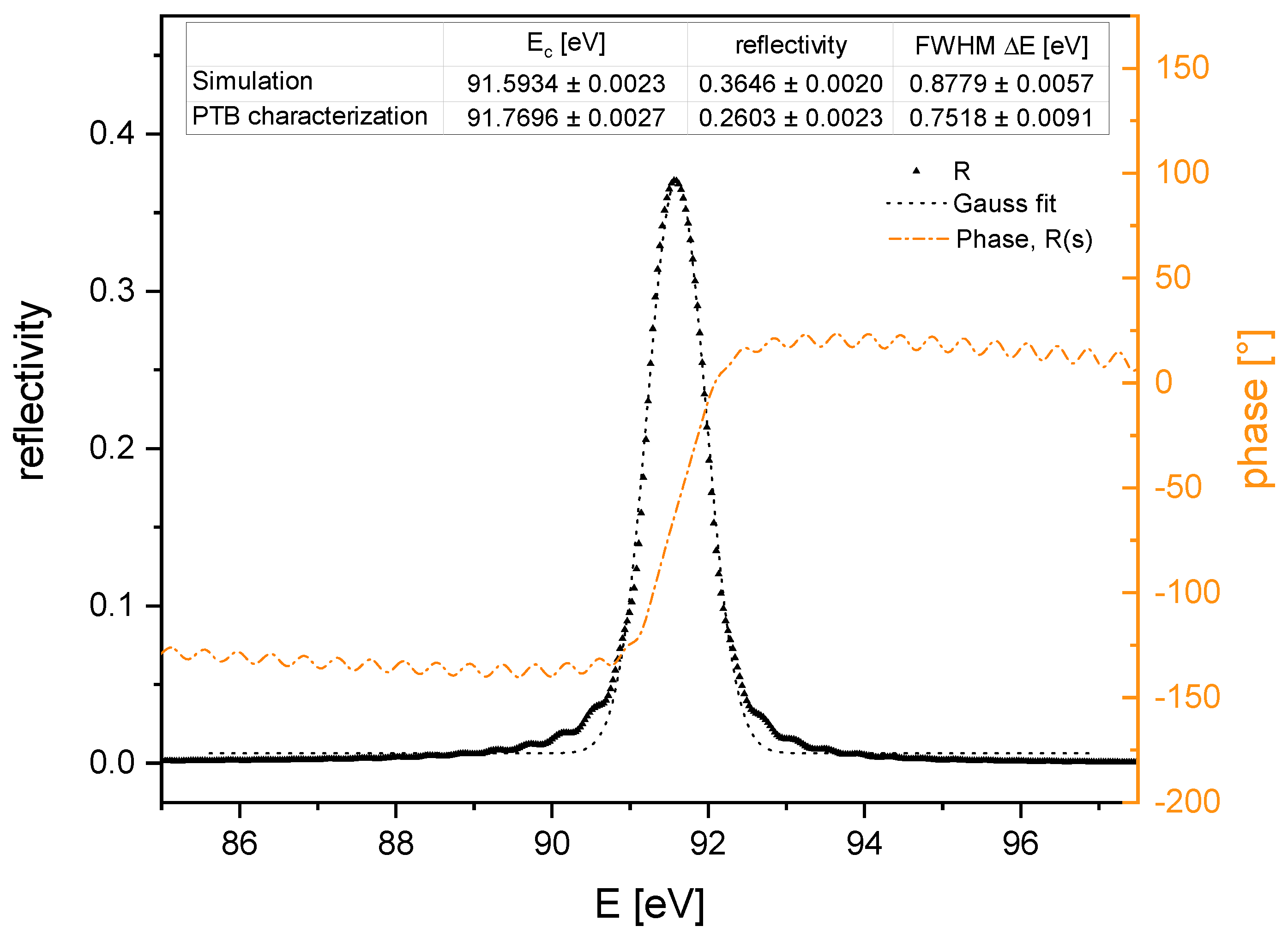
4.1. XUV Multilayer Design

The multilayer mirrors are designed to obtain a peak reflectivity at 91.6 eV at 15 angle of incidence. In the targeted photon energy range, the material combination of alternating molybdenum and silicon layers is known as the standard. The manufactured design is based on a Mo/Si stack and presented in Figure 2. Further design details are the intellectual property of OptiXfab GmbH, Jena.
The peak reflectivity is optimized for a fixed angle of incidence of 15 as a compromise between the specified tunability with a compact geometrical footprint and minimized optical aberrations as discussed in the next section.

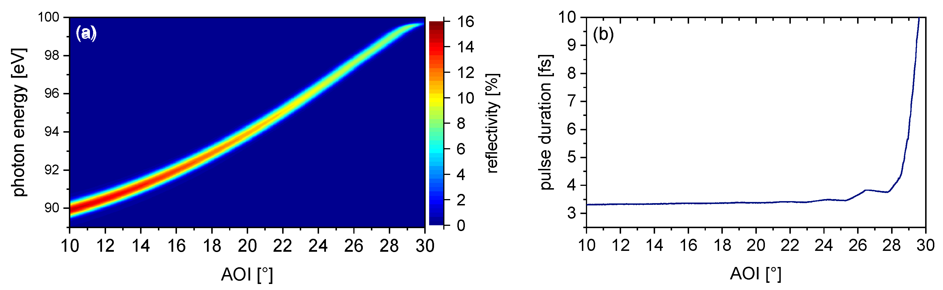
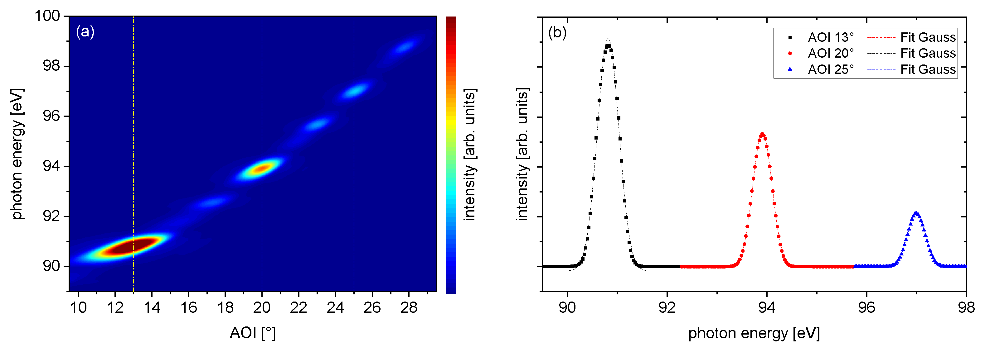
4.2. Spectral Tunability Simulation

The total reflectivity of the monochromator setup after two reflections from the multilayer mirrors is calculated from the individual reflectivity curves of the single mirrors by R 1 ( E ph ) R 2 ( E ph ) . For identical XUV mirrors, R 1 = R 2 = R , the total reflectivity is given by R 2 . In Figure 3, the reflectivity is shown as a false color plot versus the angle of incidence from 0 to 30 .
The photon energy with maximum reflectivity depends on the angle of incidence and shifts to higher photon energies with increasing angle of incidence. The peak reflectivity of approximately 14 % is reached for 90 eV photon energy at 10 , which is the smallest AOI accessible by the monochromator due to its limiting geometry. Up to 20 AOI, the total transmission drops by only 3 % . Within a tunable range of 27 AOI, the peak energy shifts from 90 eV to 98 eV corresponding to the maximum energy tunability of this monochromator setup.

4.3. Evaluation of Temporal Performance

The reflectivity’s angular dependence is presented in Figure 3a, while Figure 3b displays the temporal performance of the multilayer design, estimated using the time–bandwidth relation for Gaussian shaped pulses, utilizing the fit parameters obtained from fitting all spectra of Figure 3a.
A consistent temporal performance is noted within the angular range of 10 to 26 , featuring a pulse duration of approximately ∼3.5 fs. The pulse duration marginally increases within the angular range of 26 to 28 , which denotes the limit of angular tuning. A significant increase in pulse duration occurs when the angle of incidence is larger than 28 , which is attributed to the reflectivity spectrum approaching the silicon L III absorption edge and becoming narrower.
Thus, from the simulation, the temporal performance is expected to remain nearly constant over the entire tuning range from 10 to 28 . To achieve an even more consistent temporal behavior, the tuning range should be limited to an angular range of 10 to 26 . It is worth noting that this behavior is linked to the coating design and may vary for other coatings. Further research is required to effectively constrain the angular tuning range for the desired temporal performance.
This evaluation determines the overall temporal performance of the monochromator, excluding any distortions due to optical aberrations. The mirror M2 of the setup is designed to create a focus spot in the observation plane (OP). As a result, an increasing angle of incidence introduces optical aberrations that lead to a temporal distortion of the reflected pulse. To further investigate this phenomenon, we evaluate wavefront distortions for different radii of curvature at the design angle of 15 .
To simulate the resulting temporal delay within the lateral plane, we use a ray transfer matrix analysis. Here, the Gaussian beam is described by the complex beam parameter q 0 = i z R at its waist position. The HHG source parameters defined above are as follows:
  • Gaussian beam waist w 0 = 5 μ m;
  • Central wavelength λ c = 13.5 nm ;
  • Beam-quality factor M 2 = 1 ;
  • Mirror angles θ M 1 = θ M 2 = 15 ;
  • Distance between the two mirrors L = 34.64 mm leading to a beam offset of 20 mm .
The source distance ( L 1 ) is a variable parameter in these simulations.
We calculate the wavefront distortion along the propagation axis for fixed radii of curvature ( R O C ) of 3000 mm , 1500 mm , 1000 mm and 500 mm . The analysis is performed in an observation plane ( O P ) at a fixed position of L 2 = 1 m behind the focusing mirror M 2 , which may not be the ideal focus position in an experiment. For evaluation, the source distance L 1 is changed, and the complex beam parameter q O P is calculated:
q O P 1 = k 1 L 2 0 1 1 0 2 / R O C cos ( θ M 2 ) 1 1 L / cos ( 2 θ M 1 ) 0 1 1 0 0 1 1 L 1 0 1 q 0 1
Here, k is a normalization constant chosen to keep the second component of the ray vector equal to 1. This parameter q O P provides information about both the beam waist w O P and its radius of curvature R O P :
w O P = Im 1 q O P π n λ c 1
R O P = Re 1 q O P 1
Finally, the RMS spotsize ( R M S ) and the wavefront distortion ( W D ) are calculated in the observation plane:
R M S = 1 2 w O P
W D = | R O P | R O P 2 w O P 2 c
The evaluation of the wavefront distortion for the different curvatures as a function of source distance is shown in Figure 4a.
A relatively small pulse front distortion for this geometrical setup is found for R = 1000 mm . Here, the source distance is approximately the ROC or the double focal distance that results in a 1:1 image of the HHG source at the focus position. For very short source distances of 0.1 to 0.3 m , a mirror with a smaller ROC of R = 500 mm resulting in a real magnified image in the observation plane ( O P ) also results in a flat curve at the focus position, but at longer source distances, the wavefront distortion grows very rapidly. A mirror with ROC of 3000 mm leads to a divergent outgoing beam, resulting in a virtual image since the source distance is smaller than the focal length. The inset Figure 4a shows the behavior for very long source distances of several meters.
In Figure 4b, the corresponding rms spot size is evaluated. For the 1000 mm mirror, the image distance is around 0.9 m . Angular tuning slightly changes the source distance. Within 100 mm shift, the increase in the spot size remains small compared to a ROC of R = 500 mm , where the optimum source distance is about 0.25 m . For ROC = 3000 mm , the optimum is at extremely long source distances, but the position of the evaluation is comparably short such that the change in the spot size remains small over the full simulation range of 10 m. Here, the limited rms spot size results from the aperture of the 1 / 2 inch mirrors of the monochromator themselves.
The Rayleigh range is 0.58 m according to Equation (3) for the source spot radius of 5 μ m , which is nicely reproduced for a ROC = 1000 mm including an AOI of 15°.
The calculations above were performed for a monochromatic wave at 13.5 nm with a Gaussian intensity profile. Under typical experimental conditions, the reflected HHG spectrum is modulated, reproducing the odd multiples of the driving laser frequency with a finite bandwidth for each harmonic in the plateau region. Even in the cut-off region, the spectral amplitude drops rapidly for increasing photon energy for the chosen laser characteristics.
To simulate our experimental conditions, the reflectivity matrix of the multilayer mirror monochromator is multiplied with an HHG spectrum in the given spectral range. From this, we obtain the angle-dependent transmission expected for our HHG experiment. Figure 5 shows the reflectivity curve of the monochromator versus AOI. The amplitude modulation from the distinct harmonic peaks is clearly visible. The highest reflectivity is obtained for an angle of 13 resulting from the maximum of the HHG spectrum used for convolution at ∼91 eV.
The spectra with peak reflectivity for AOI 13 , 20 and 25 are analyzed with a Gaussian fit to determine the peak photon energy E c and the FWHM bandwidth Δ E c , respectively, and presented in Table 1. The results show a bandwidth clearly below the design guidelines of <0.8 eV in the covered tuning range of the monochromator. Furthermore, we can expect near-Fourier-limited pulses according to the phase behavior of the multilayer presented in Figure 2, which exhibits the expected performance of the monochromator for the reflection by two plane mirrors. For better comparison, Table 2 presents the results of the experimental verification from the following section. Note that the maximum energy analyzed deviates by an AOI of 1 in the experimental dataset due to the typical experimental deviations in HHG.
Taking the wavefront mismatch and thus the pulse front distortion into account, if M 2 is chosen to be a focusing mirror, the ideal performance with a distance L 1 = 0.9 m and L 2 = 1 m is provided by a mirror with ROC = 1000 mm showing a local minimum in pulse front distortion and spot size according to the analysis presented in Figure 4. This defines a lower limit caused by wavefront distortion in a pump–probe geometry with copropagating pulses substantially <250 as. We denote that for the given design restrictions, this setup is thus limited by the bandwidth of the mirrors and could even be used for spectral tuning in the attosecond regime.

5. Experiment

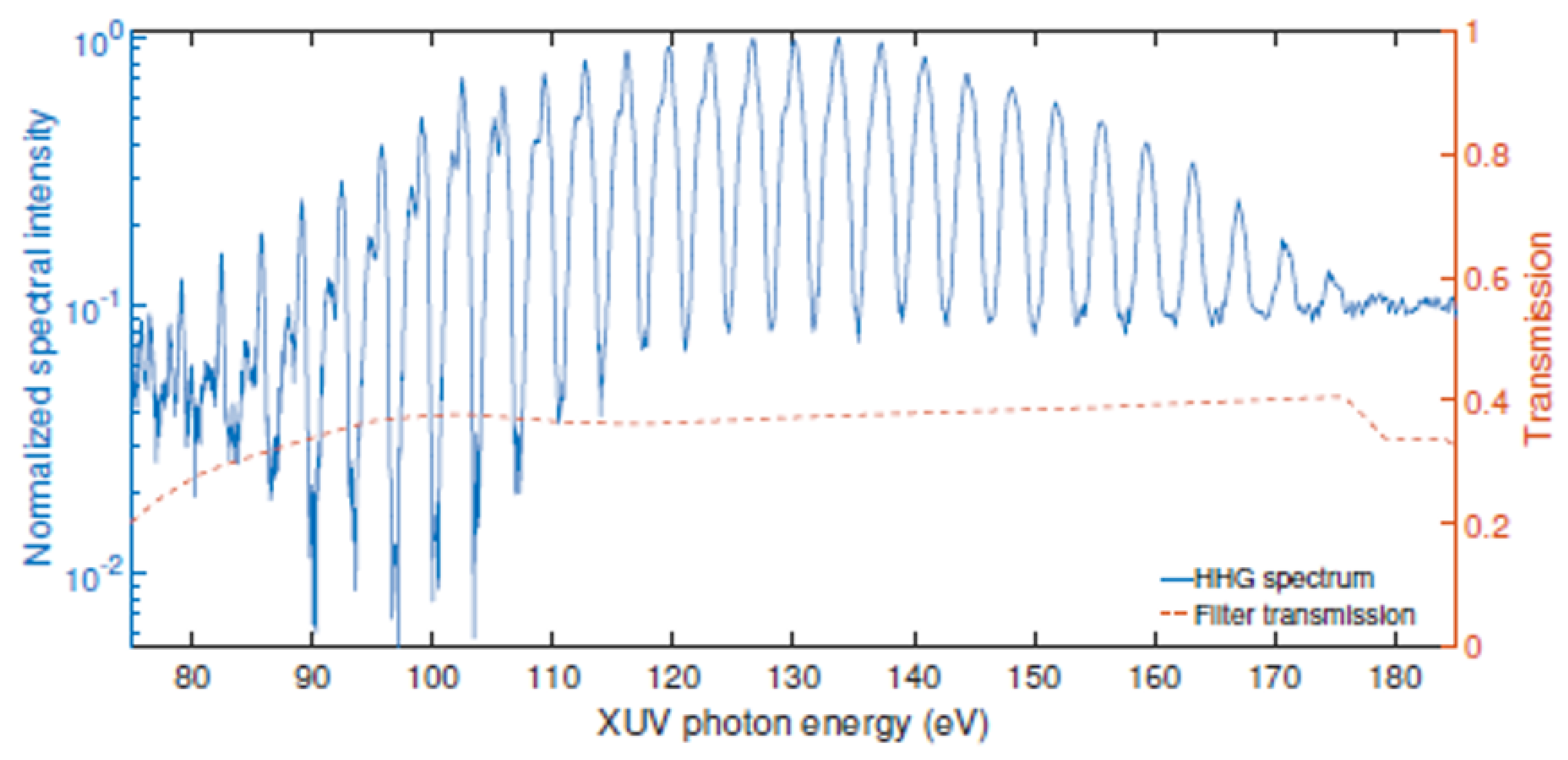
5.1. Laser System and HHG

For the experimental characterization of the monochromator transmission and tunability, a commercial Ti:sapphire chirped-pulse amplifier (CPA) is used with the following specifications:
  • Δ τ = 35 fs ;
  • E = 5 mJ ;
  • Center wavelength: 803 nm;
  • Repetition rate: 3 kHz;
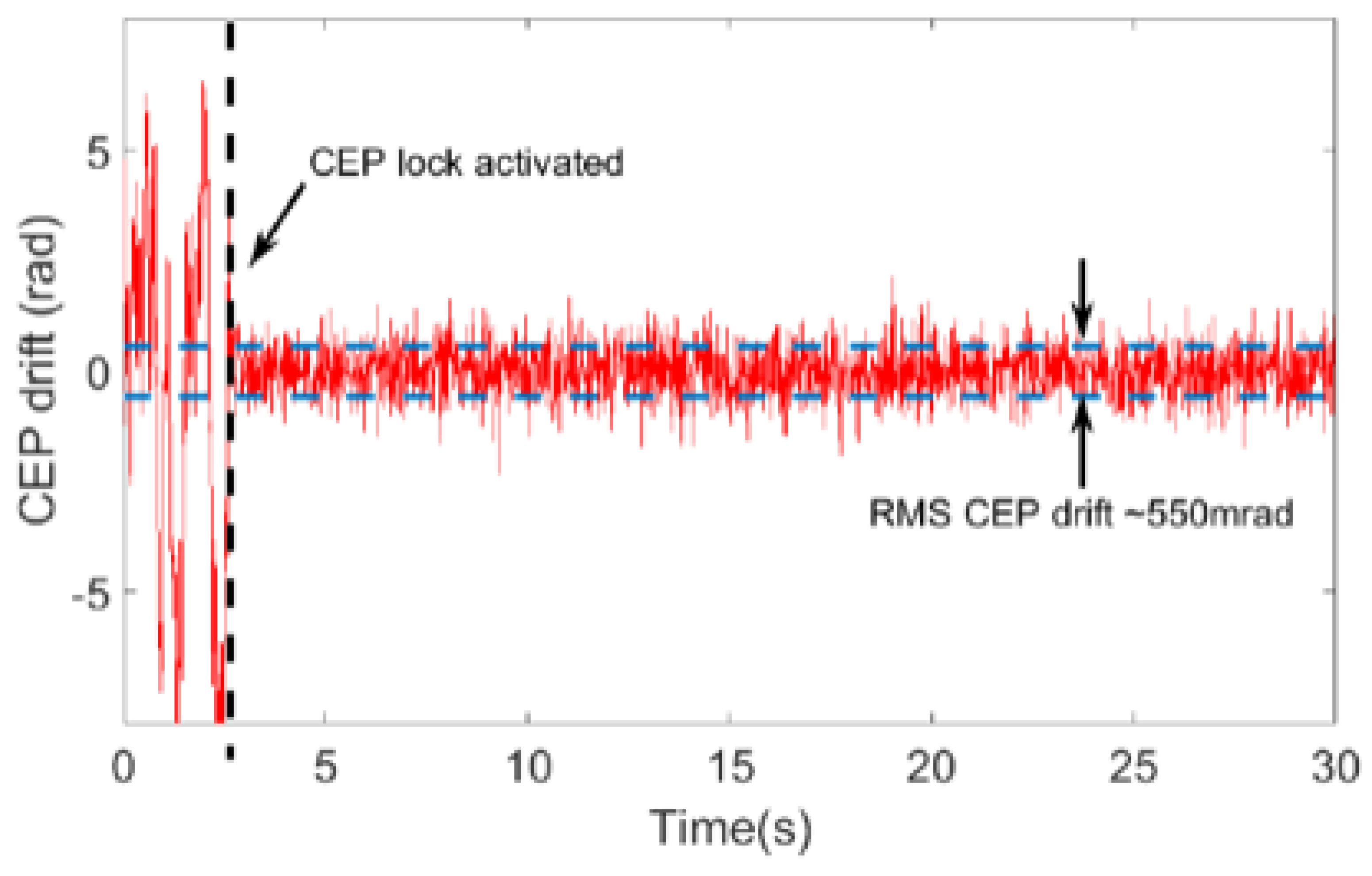
  • CEP stability: 320 mrad rms
  • gas-filled hollow-core fiber (HCF) compression to Δ τ = 5.3 fs .
The laser system provides the general capability to use either the direct output pulse with a duration of 35 fs for HHG as well as the cut-off spectrum from the HCF-compressed pulses. For spectral characterization of the multilayer monochromator, we chose the longer pulse for HHG to demonstrate the ability to isolate a spectral bandwidth defined by the XUV mirror coating from the HHG plateau range. Experimentally, this provides a much higher photon flux than using the HHG cut-off range for characterization.
The laser pulses are focused with a f = 250 mm spherical mirror into a neon gas target for HHG. The gas target is a steel tube with an inner diameter of 4 mm with a backing pressure of 200 mbar . To suppress the fundamental laser pulse, a 200 nm-thin Zr filter is used.
A commercial slit grating spectrometer (McPherson 251MX XUV) with two flat-field gratings covering a total spectral range Δ E from 15.5 eV to 248 eV is used for spectral characterization. The spectrally resolved HHG is detected by a Newton 940 back-thinned XUV CCD camera (Andor Technology Ltd., Belfast, UK). The camera is cooled down to −50 °C during the measurement for improved signal-to-noise ratio.

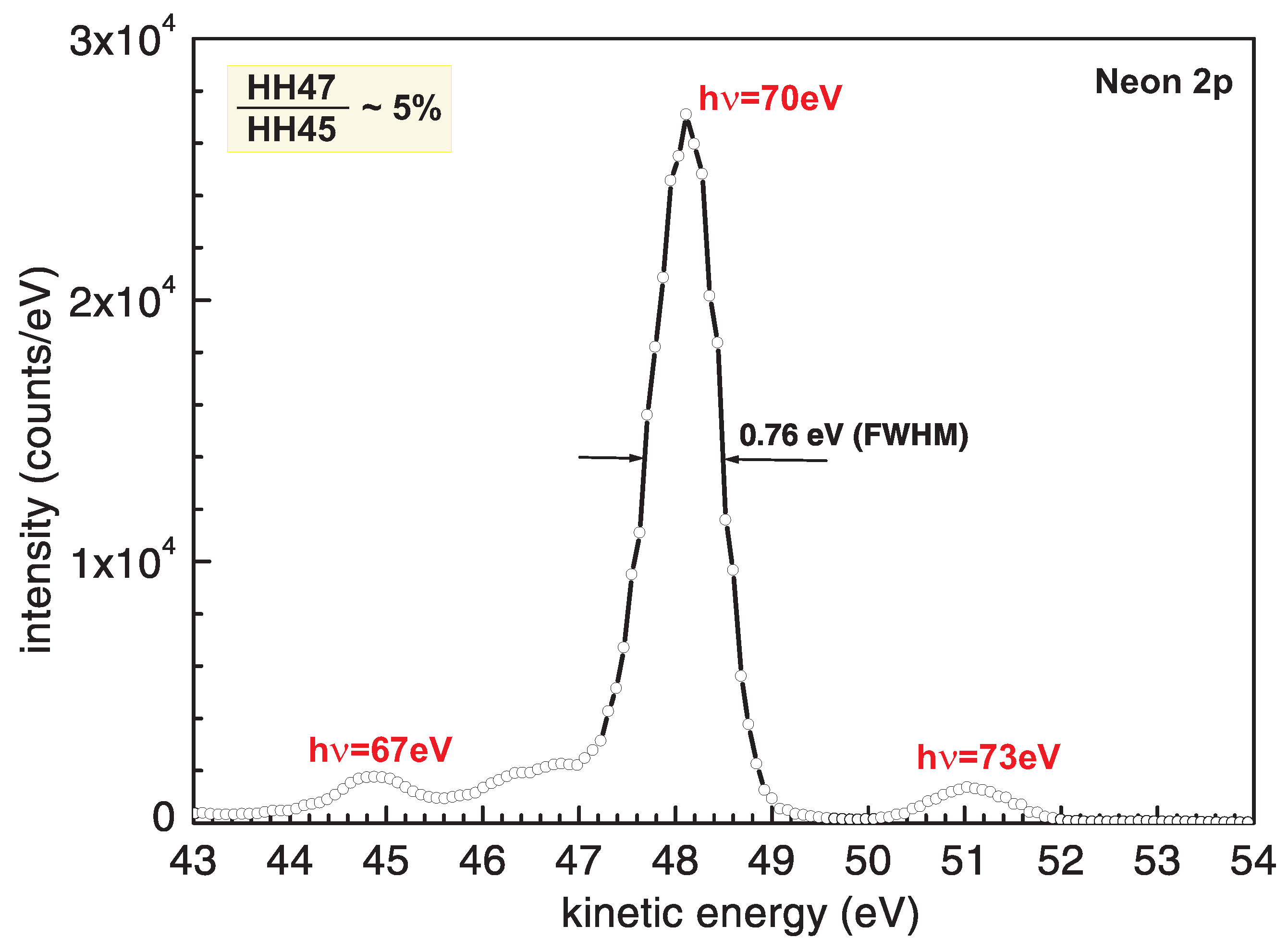
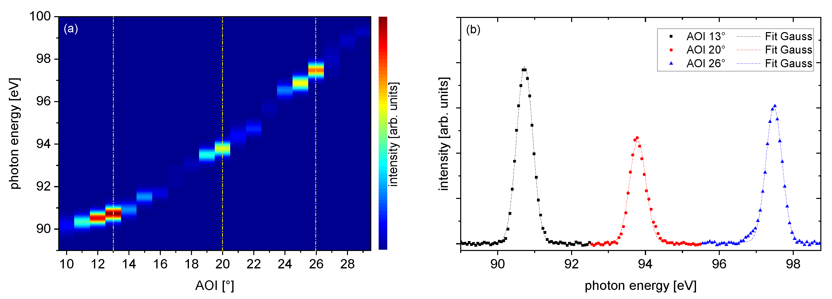
5.2. Multilayer Mirror Monochromator Characterization

Figure 6a shows the monochromatized high-harmonic spectra measured with the XUV spectrometer after polynomial background subtraction. We analyze the three intensity peaks at AOI 13 , 20 and 26 . The corresponding spectra are shown in Figure 6b, and the data are summarized in Table 2. The same analysis as in the theoretical investigation is used to determine the center photon energy and the FWHM bandwidth of the monochromatized beams.
From the experimental data, one can see that the bandwidth is nearly constant at 518 meV, providing a constant pulse duration over the tuning range analyzed according to the measurements performed. For further investigation, a time-resolved pump–probe experiment would be required to directly determine reflected bandwidth and XUV pulse duration.

6. Conclusions and Discussion

We presented the design, simulation and experimental characterization of an ultra-narrowband multilayer XUV monochromator. The designed mirror pair allows using this setup as a time-preserving XUV monochromator limited by the given bandwidth of the mirrors found to be 0.52 eV and capable of even higher temporal resolution much below <250 as with a geometrically limited spectral tuning range of roughly 8 eV. The total reflectivity reaches up to 13% for the design wavelength. The operation regime of the monochromator can be adapted by tailoring the multilayer coating to the required experimental conditions. For experiments requiring a dedicated photon energy, this monochromator offers the smallest known footprint with the benefit of a quasi-inline setup. The small footprint allows to insert this monochromator even in compact experimental setups. The peak intensity in the experiment is reached at 13 and 90.73 eV with a FWHM bandwidth of 0.52 eV . To our best knowledge, this is the smallest bandwidth reported for a multilayer monochromator in the given energy range, even for pure monochromatization.
The final design supports a narrow bandwidth that is even smaller than the comparable arrangements in the combination of multilayer coated gratings. Kleineberg et al. [12] demonstrated a monochromator for microspot-XPS experiments using synchrotron radiation at BESSY I at 95 eV with a corresponding bandwidth of 0.7 eV. Further experiments with HHG sources demonstrate a reflected bandwidth in the range of 1.5 eV and 2.5 eV [13,14] in the 40 eV to 70 eV range, respectively.
The bandwidth of the monochromator design presented here is substantially smaller and will provide even better spectroscopic resolution with respect to the inner-shell photoelectron spectroscopy using the high harmonic source presented by Drescher et al. [23].
An upper limit for the contrast ratio to neighboring harmonics is better then 20% based on the sensitivity of the back-thinned CCD camera used in this experiment (Newton 940, Andor Technology Ltd.). With respect to comparable geometries utilizing periodic multilayer mirrors (e.g., [23]), we expect a similar contrast ratio in the range of 5% as shown in Figure A4.
For the given bandwidth of 0.52 eV and a corresponding Fourier limited pulse duration in the range of 3 fs, the calculated G D D 0.157 fs2 is negligible. The main pulse distortions arise from amplitude effects by the adjustable angle of incidence (AOI). For large AOI, a strongly reduced bandwidth and distorted spectral shape from the silicon edge at 100 eV are the dominant effects for temporal distortion.
The small footprint allows for easy integration into current HHG setups and provides a fixed focal position minimizing the mismatch between the sagittal and tangential focus caused by the tilted spherical mirror.
We demonstrated that the wavefront error at the focus position is sufficiently small to provide near Fourier transform-limited pulses, even if the focal intensity distribution is affected by astigmatism.
An ideal proof-of-principle experiment for a final evaluation of the bandwidth and performance of the presented setup is a time-resolved photoionization experiment in krypton to determine the temporal performance as well as the overall contrast of the setup, studying the Kr M 4 , 5 N 1 M 2 , 3 Auger decay with a sufficient resolution to excite the 3D spin components ( E 3 d 3 / 2 = 95 eV and E 3 d 5 / 2 = 93.8 eV ), independently tuning the monochromator, as well as extracting the XUV bandwidth from the 4p photoelectron emission following the experimental work in [24,25,26].
This demonstrates that the XUV multilayer mirror monochromator provides the general capability of a pulse-preserving tunability of 8 eV bandwidth, supporting near Fourier transform-limited pulses down into the attosecond regime.

Author Contributions

Conceptualization, T.U. and T.N.; methodology, Y.Y., R.E.M., O.D.M. and J.H.; software, T.N.; validation, T.N., Y.Y. and R.E.M.; formal analysis, T.N., J.H. and T.U.; resources, F.X.K. and T.U.; data curation, T.N., J.E., Y.Y. and O.D.M.; writing—original draft preparation, T.U., J.H. and O.D.M.; writing—review and editing, all contributors; visualization, T.N., J.E., Y.Y., T.U. and O.D.M.; supervision, T.U. and F.X.K.; funding acquisition, F.X.K. and T.U., T.N., Y.Y. and J.H. contributed equally to this work. All authors have read and agreed to the published version of the manuscript.

Funding

This research received external funding by the Landesexzellenzcluster “Frontiers in Quantum Photon Science”, the Joachim Herz Stiftung and the Cluster of Excellence “Advanced Imaging of Matter” (EXC 2056—project ID 390715994) of the Deutsche Forschungsgemeinschaft.

Data Availability Statement

The data that support the findings of this study are available from the corresponding author upon reasonable request.

Acknowledgments

We gratefully acknowledge support from U. Heinzmann for basic considerations of the monochromator design and M. Wick for discussions and support on the simulation of the pulse front distortion.

Conflicts of Interest

The authors declare no conflicts of interest.

Appendix A. Laser Characterization

Appendix A.1. Commercial CEP-Stabilized Ti:Sapphire CPA System

The seed oscillator is a Kerr-lens mode-locked Ti:sapphire laser oscillator (Vitara from Coherent Inc., Santa Clara, CA, USA), which delivers 15 fs pulses at 80 MHz repetition rate and an average output power of 450 mW. The pulses from the oscillator are split into two parts. The portion of the beam with lower energy is used for active carrier-envelope phase (CEP) stabilization, which will be described later in Appendix A.3. Most of the pulse energy is sent as seed into the CPA system.
In the Ti:sapphire CPA (Legend Elite Duo-USP-1k-HP by Coherent Inc.), after regenerative amplification of the seed, the pulse energy is further amplified to more than 6 mJ by a single-pass booster amplifier. After the grating compressor, the pulses are compressed to ∼35 fs, and the pulse energy is 5 mJ at 3 kHz repetition rate.

Appendix A.2. Hollow-Core Fiber Compression

The duration of the pulses from the CPA system is approximately 35 fs. Although several gating techniques for the generation of isolated attosecond XUV pulses using HHG from multicycle driver pulses [27] have been developed, the standard routine approach to obtain isolated attosecond pulses is to first compress the pulses down to two- or single-cycle durations with output pulse energies up to a few mJs in noble-gas-filled hollow-core fiber (HCF) compressors [28,29].
In this scheme, the pulses are first spectrally broadened during propagation in the noble gas and subsequently recompressed with chirped mirrors.
At the HCF output, the laser spectrum is broadened compared to the input spectrum as shown in Figure A1a. The spectrum covers from 400 nm to 1000 nm, which is more than one octave of spectral bandwidth. The input pulse energy is 2.1 mJ, and the output pulse energy is 1.05 mJ. In this experiment, the HCF (length 1 m, inner core diameter 400 μ m) was filled with 2.6 bar of neon gas as the nonlinear medium.
Figure A1. Laser pulse characterization: (a) Ti:sapphire CPA output spectrum (blue curve), hollow-core-fiber output spectrum (red curve). (b) Measured SHG-FROG trace. (c) Retrieved temporal intensity (blue) and phase (red) profiles. The transform-limited intensity profile is shown as a dashed green curve.
Photonics 11 00525 g0a1
The HCF output pulses are then recompressed with double-chirped mirror (DCM) pairs. The custom-designed DCMs employed in our setup have a bandwidth of 500–1000 nm and GDD of −50 fs2. It takes five bounces off the DCM pairs (i.e., in total, 10 reflections) to compensate for the dispersion of the HCF output pulses. Two additional reflections on a DCM pair are needed to compensate for the dispersion of a pair of fused silica wedges and the vacuum chamber’s 1 mm-thick fused silica input window. The fused silica wedges are for precise dispersion compensation and also for tuning the pulse CEP. With this configuration, the pulses are compressed to minimum duration in the HHG gas target.
Figure A1b shows the measured FROG trace for temporal characterization of the HCF pulses. The reconstructed FROG trace (not shown) matches well with the experimentally measured trace. The retrieved temporal intensity profile and temporal phase are shown in Figure A1c. The transform-limited (TL) intensity profile calculated from the pulse spectrum is shown in Figure A1c (green dashed line) for comparison. The measured pulse duration is ∼5.3 fs, and the TL pulse duration is 4.3 fs.

Appendix A.3. CEP Stability and CEP Dependence of HHG

Depending on the targeted experiment, either 35 fs long pulses directly from the Ti:sapphire CPA system or sub-6 fs pulses from the HCF compressor (HCF pulses) can be used for our HHG experiments. The laser pulses are then focused into a gas target for HHG using a spherical mirror.
The gas target follows a conventional gas tube design. It is a steel tube with 4 mm inner diameter and sealed at one end. Two pre-drilled 1 mm holes on the tube allow the focused laser beam to pass through. The tube is mounted on a 3D translation stage to optimize the HHG signal. The gas target is moved in the plane perpendicular to the laser propagation direction for centering the drilled hole to the laser beam and along the laser propagation direction to optimize the phase-matching condition.
The XUV spectrometer used in our attoscience beamline is a McPherson 251MX XUV spectrometer. The spectrometer is equipped with two concave varied line-spacing (VLS) flat-field gratings. Using the concave grating with varied groove spacing, the diffracted rays focus sharply onto a plane. The grating holder allows switching between different gratings under vacuum operation via the grating switching handle. One grating has a nominal groove density of 300 groove/mm and covers the 20–80 nm (15.5–62 eV) spectral range. The second grating has a nominal groove density of 1200 groove/mm and covers spectral range of 5–20 nm (62–248 eV).
At the entrance of the spectrometer, a filter wheel is located, which contains several thin metallic filters. After the HHG gas target, the XUV beam and the laser pulses propagate collinearly towards the XUV spectrometer. Since the HHG conversion efficiency is extreme low (on the order of η = 10 6 ), the XUV signal observed with the XUV spectrometer will be buried under the driving laser background signal. The metallic filters block the laser pulses while allowing substantial transmission of the XUV beam. The XUV beam will then go through an adjustable slit and a fixed opening. These two apertures fix the beam pointing and the incident angle on the grating. Another aperture is mounted on the grating mount, which allows one to center the grating with respect to the incident beam.
The XUV CCD camera is a Newton 940 back-illuminated CCD with 2048 by 512 pixels from Andor Technology Ltd. The pixel size is 13.5 μ m × 13.5 μ m. The camera can be cooled down to −60 °C with air-cooling and −100 °C with water-cooling for dark current suppression. A zeroth-order baffle is placed in front of the CCD camera to block the zeroth diffraction order of the grating.
High-energy XUV photons can be generated via HHG in noble gas. In Figure A2, a spectrum of HHG from neon covering up to 180 eV is shown. The HHG spectrum is generated with 35 fs 1 mJ laser pulses close to the laser parameters used for the XUV monochromator characterization. The HHG target is backed with 200 mbar of neon gas. The focal length of the focusing optics is 500 mm. One 300 nm thick zirconium filter is used to block the IR driving pulses.
Figure A2. HHG in neon up to 180 eV photon energy: the HHG spectrum (blue curve) is generated with 35 fs 1 mJ laser pulses. The HHG gas target is backed with 200 mbar of neon gas. The focal length of the focusing optics is 250 mm. One 200 nm-thick zirconium filter is used to block the IR driving pulses. The Zr transmission curve is also shown (red).
Photonics 11 00525 g0a2
The Ti:sapphire CPA system is actively CEP stabilized, which is a prerequisite to generate isolated attosecond pulses or—with respect to the presented multilayer monochromator—to provide a continuous cut-off spectrum with a sufficiently broad bandwidth generated by a single trajectory.
When both fast and slow loops are activated, the residual RMS CEP noise amounts to 320 mrad (single shot) (compare Figure A3).
Figure A3. CEP stability measurement with stabilization loops on and off as well as a long term measurment for reference indicating a RMS CEP of <550 mrad for the given graph.
Photonics 11 00525 g0a3

Appendix B. Optical Properties

Appendix B.1. Expected Extinction Ratio

The extinction ratio for the selected harmonic bandwidth can only be determined in the current experiment by the quantum efficiency of the Newton 940 back-illuminated CCD from Andor Technology Ltd. to be ∼80% in the given energy range. This represents an upper limit for the and is expected to be significantly better.
Figure A4 shows a measurement done with a comparable setup and a reflection from two identical XUV mirrors in the 70 eV range. To determine the extinction of the selected peak to the neighboring harmonics, the Neon 2p photoelectron emission is measured with a TOF photoelectron spectrometer. The neighboring harmonics are sufficiently resolved to determine the extinction ratio to be in the order of 5% with respect to the 2p photoelectron peak.
Based on this measurement and further references, e.g., [23], the lower limit for the setup demonstrated in this work is expected to be in this range as well.
Figure A4. TOF photoelectron spectrum of the Neon 2p electrons from a similar setup. The set of XUV mirrors is designed for h ν = 70 eV peak reflectivity. The measured extinction ratio to neighboring harmonics is in the order of 5% [30].
Photonics 11 00525 g0a4

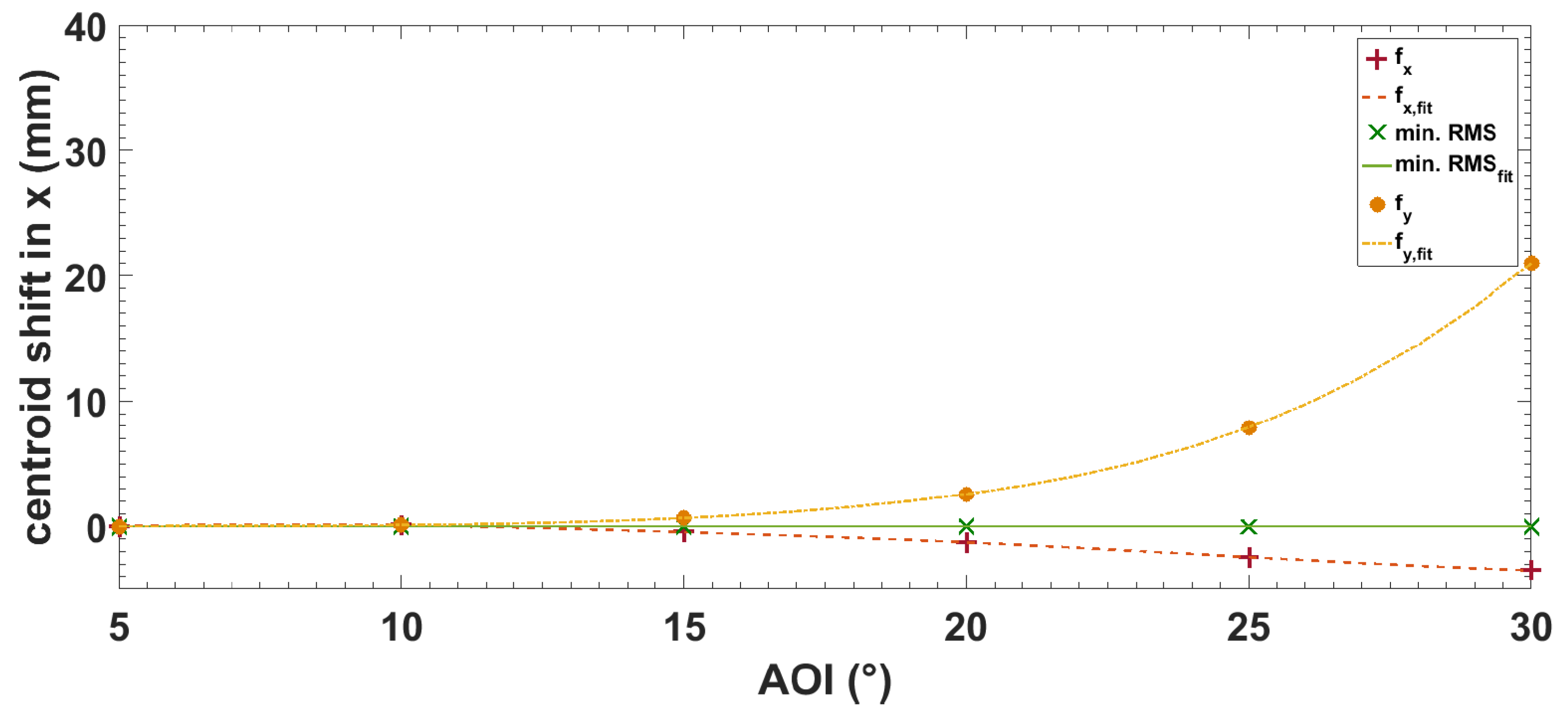
Appendix B.2. Astigmatic Centroid Size

The tilted mirror reflection causes mainly astigmatism resulting in an astigmatic focal shift depending on the AOI. The astigmatic behavior was simulated to determine the influence on focal size and position according to the AOI.
Figure A5 shows the shift of the ideal centroid position in the x and y planes in dependence of the AOI. The positions of the image point of minimum RMS spot size are analyzed in the image surface (IMS) and along the optical beam path. The centroid position is related to the reference ray position in the image surface. The reference ray in the optical design of the MMM maintained the 20 mm horizontal beam offset. The centroid positions of the focus fx, fy and the minimum RMS spot size are calculated on the propagation axis for incident angles θ from 5° to 30° in 5°-steps.
Figure A5. Centroid shift provided by astigmatic focusing from the spherical mirror.
Photonics 11 00525 g0a5
The increasing mismatch is in agreement with a substantial change in the intensity shape at the minimum focal point, which cannot be expressed with the ellipticity parameter (roundness) of the beam for the angular tuning range demonstrated in this work. With increasing AOI, the intensity shape turns to look like a cross at 15° AOI and becomes even more distorted for larger AOI. Nevertheless, in Figure 4, it is shown that this effect has no influence on the time structure of the pulse at the focal position.
For experiments that are sensitive to the local intensity distribution in the focal plane, the operational AOI needs to be reduced due to the existing astigmatism.

References

  1. Teichmann, S.M.; Silva, F.; Cousin, S.L.; Hemmer, M.; Biegert, J. 0.5-keV Soft X-ray attosecond continua. Nat. Commun. 2016, 7, 11493. [Google Scholar] [CrossRef]
  2. Ishii, N.; Kaneshima, K.; Kitano, K.; Kanai, T.; Watanabe, S.; Itatani, J. Carrier-envelope phase-dependent high harmonic generation in the water window using few-cycle infrared pulses. Nat. Commun. 2014, 5, 3331. [Google Scholar] [CrossRef] [PubMed]
  3. Pertot, Y.; Schmidt, C.; Matthews, M.; Chauvet, A.; Huppert, M.; Svoboda, V.; von Conta, A.; Tehlar, A.; Baykusheva, D.; Wolf, J.P.; et al. Time-resolved X-ray absorption spectroscopy with a water window high-harmonic source. Science 2017, 355, 264–267. [Google Scholar] [CrossRef]
  4. Chini, M.; Zhao, K.; Chang, Z. Broadband Isolated Attosecond Pulses: Generation, Characterization, and Applications. arXiv 2013, arXiv:1312.1679. [Google Scholar] [CrossRef]
  5. Hofstetter, M.; Schultze, M.; Fieß, M.; Dennhardt, B.; Guggenmos, A.; Gagnon, J.; Yakovlev, V.S.; Goulielmakis, E.; Kienberger, R.; Gullikson, E.M.; et al. Attosecond dispersion control by extreme ultraviolet multilayer mirrors. Opt. Express 2011, 19, 1767. [Google Scholar] [CrossRef] [PubMed]
  6. Schultze, M.; Goulielmakis, E.; Uiberacker, M.; Hofstetter, M.; Kim, J.; Kim, D.; Krausz, F.; Kleineberg, U. Powerful 170-attosecond XUV pulses generated with few-cycle laser pulses and broadband multilayer optics. New J. Phys. 2007, 9, 243. [Google Scholar] [CrossRef]
  7. Cousin, S.L.; Di Palo, N.; Buades, B.; Teichmann, S.M.; Reduzzi, M.; Devetta, M.; Kheifets, A.; Sansone, G.; Biegert, J. Attosecond Streaking in the Water Window: A New Regime of Attosecond Pulse Characterization. Phys. Rev. X 2017, 7, 041030. [Google Scholar] [CrossRef]
  8. Gaumnitz, T.; Jain, A.; Pertot, Y.; Huppert, M.; Jordan, I.; Ardana-Lamas, F.; Wörner, H.J. Streaking of 43-attosecond soft-X-ray pulses generated by a passively CEP-stable mid-infrared driver. Opt. Express 2017, 25, 27506. [Google Scholar] [CrossRef] [PubMed]
  9. Villoresi, P. Compensation of optical path lengths in extreme-ultraviolet and soft-x-ray monochromators for ultrafast pulses. Appl. Opt. 1999, 38, 6040. [Google Scholar] [CrossRef]
  10. Frassetto, F.; Bonora, S.; Vozzi, C.; Stagira, S.; Zanchetta, E.; Della Giustina, G.; Brusatin, G.; Poletto, L. Active-grating monochromator for the spectral selection of ultrashort pulses. Optics Express 2013, 21, 12996. [Google Scholar] [CrossRef]
  11. Poletto, L.; Miotti, P.; Frassetto, F.; Spezzani, C.; Grazioli, C.; Coreno, M.; Ressel, B.; Gauthier, D.; Ivanov, R.; Ciavardini, A.; et al. Double-configuration grating monochromator for extreme-ultraviolet ultrafast pulses. Appl. Opt. 2014, 53, 5879. [Google Scholar] [CrossRef] [PubMed]
  12. Kleineberg, U.; Menke, D.; Hamelmann, F.; Heinzmann, U.; Schmidt, O.; Fecher, G.; Schoenhense, G. Photoemission microscopy with microspot-XPS by use of undulator radiation and a high-throughput multilayer monochromator at BESSY. J. Electron Spectros. Relat. Phenom. 1999, 101–103, 931–936. [Google Scholar] [CrossRef]
  13. Takahashi, E.J.; Hatayama, M.; Ichimaru, S.; Midorikawa, K. Dispersion-free monochromatization method for selecting a single-order harmonic beam. arXiv 2015, arXiv:1502.05124. [Google Scholar]
  14. Hatayama, M.; Ichimaru, S.; Ohcni, T.; Takahashi, E.J.; Midorikawa, K.; Oku, S. Wide-range narrowband multilayer mirror for selecting a single-order harmonic in the photon energy range of 40–70 eV. Optics Express 2016, 24, 14546. [Google Scholar] [CrossRef] [PubMed]
  15. Poletto, L.; Tondello, G. Time-compensated extreme-UV and soft x-ray monochromator for ultrashort high-order harmonic pulses. J. Opt. Pure Appl. Opt. 2001, 3, 374–379. [Google Scholar] [CrossRef]
  16. Guo, Q.; Dendzik, M.; Grubišić-Čabo, A.; Berntsen, M.H.; Li, C.; Chen, W.; Matta, B.; Starke, U.; Hessmo, B.; Weissenrieder, J.; et al. A narrow bandwidth extreme ultra-violet light source for time- and angle-resolved photoemission spectroscopy. Struct. Dyn. 2022, 9, 024304. [Google Scholar] [CrossRef]
  17. Yang, Y.; Hengster, J.; Neumann, T.; Mainz, R.E.; Mücke, O.D.; Kärtner, F.X.; Uphues, T. A time-preserving ultra-narrow-bandwidth multilayer-mirror monochromator for extreme ultraviolet pulses. In Proceedings of the Conference on Lasers and Electro-Optics, San Jose, CA, USA, 13–18 May 2018; Volume Part F92-C, p. JTu2A.157. [Google Scholar] [CrossRef]
  18. Spiller, E.A. Soft X-ray Optics; SPIE Optical Engineering Press: Bellingham, WA, USA, 1994; p. 290. [Google Scholar]
  19. Attwood, D.; Sakdinawat, A. X-rays and Extreme Ultraviolet Radiation; Cambridge University Press: Cambridge, UK, 2016. [Google Scholar] [CrossRef]
  20. Suman, M.; Frassetto, F.; Nicolosi, P.; Pelizzo, M.G. Design of aperiodic multilayer structures for attosecond pulses in the extreme ultraviolet. Appl. Opt. 2007, 46, 8159. [Google Scholar] [CrossRef] [PubMed]
  21. Guggenmos, A.; Rauhut, R.; Hofstetter, M.; Hertrich, S.; Nickel, B.; Schmidt, J.; Gullikson, E.M.; Seibald, M.; Schnick, W.; Kleineberg, U. Aperiodic CrSc multilayer mirrors for attosecond water window pulses. Opt. Express 2013, 21, 21728. [Google Scholar] [CrossRef] [PubMed]
  22. Hecht, E. Optics, 4th ed.; Addison Wesley: Reading, UK, 2002. [Google Scholar]
  23. Drescher, M.; Siffalovic, P.; Spieweck, M.; Heinzmann, U. Applicability of monochromatized high harmonic extended ultraviolet radiation for inner-shell photoelectron spectroscopy. J. Electron Spectrosc. Relat. Phenom. 2002, 127, 103–108. [Google Scholar] [CrossRef]
  24. Drescher, M.; Hentschel, M.; Kienberger, R.; Uiberacker, M.; Yakovlev, V.; Scrinzi, A.; Westerwalbesloh, T.; Kleineberg, U.; Heinzmann, U.; Krausz, F. Time-resolved atomic inner-shell spectroscopy. Nature 2002, 419, 803–807. [Google Scholar] [CrossRef]
  25. Uphues, T.; Schultze, M.; Kling, M.F.; Uiberacker, M.; Hendel, S.; Heinzmann, U.; Kabachnik, N.M.; Drescher, M. Ion-charge-state chronoscopy of cascaded atomic Auger decay. New J. Phys. 2008, 10, 025009. [Google Scholar] [CrossRef]
  26. Hütten, K.; Mittermair, M.; Stock, S.O.; Beerwerth, R.; Shirvanyan, V.; Riemensberger, J.; Duensing, A.; Heider, R.; Wagner, M.S.; Guggenmos, A.; et al. Ultrafast quantum control of ionization dynamics in krypton. Nat. Commun. 2018, 9, 719. [Google Scholar] [CrossRef] [PubMed]
  27. Sansone, G.; Poletto, L.; Nisoli, M. High-energy attosecond light sources. Nat. Photonics 2011, 5, 655–663. [Google Scholar] [CrossRef]
  28. Krausz, F.; Ivanov, M. Attosecond physics. Rev. Mod. Phys. 2009, 81, 163–234. [Google Scholar] [CrossRef]
  29. Chang, Z. Fundamentals of Attosecond Optics; CRC Press: Boca Raton, FL, USA, 2016. [Google Scholar] [CrossRef]
  30. Uphues, T. Adaptive Femtosecond Laser Pulse Shaping for High Harmonic Optimization. Diploma Thesis, University Bielefeld, Molecular and Surface Physics, Bielefeld, Germany, 2003. [Google Scholar]
Figure 1. Top: Sketch of the simulated optical setup of the multilayer mirror monochromator. HHG source ( S HHG ), XUV multilayer mirrors ( M 1 , M 2 ), observation plane ( O P ), lateral displacement of the XUV mirrors (L), distance S HHG to M 1 ( L 1 ), distance M 2 to O P ( L 2 ), rotation angles of the mirrors θ M 1 , θ M 2 . The mirror M 2 is chosen to be the focusing mirror in our setup. Bottom: Principal setup of the monochromator with beam path. The Z-shape geometry leads to a parallel offset of the output beam of 20 mm . The outer dimensions of ( 275 × 95 ) mm 2 show the compactness of the setup. The components are as follows: M 1 , flat XUV mirror; M 2 , curved XUV mirror; L S , linear stages; and R S , rotary stages. The big blue arrows indicate the main degrees of freedom for achieving spectral tunability.
Photonics 11 00525 g001
Figure 2. Reflectivity and phase of the special narrow-band multilayer design by OptiXfab according to the given specifications.
Photonics 11 00525 g002
Figure 3. (a) Reflected spectrum of the monochromator for two reflections depending on angle of incidence (AOI), (b) pulse duration depending on the angle of incidence (AOI) calculated by evaluation of the time–bandwidth product (TBP) from Gaussian fits to the spectra shown in panel (a).
Photonics 11 00525 g003
Figure 4. Simulation of the spot size and wavefront distortion for a fixed position L 2 = 1 m behind the second monochromator mirror M 2 for different radii of curvature R (in mm) and a variable source distance L 1 . The insets in (a,b) show the same curves over a wider source distance range.
Photonics 11 00525 g004
Figure 5. (a) Simulated spectra behind the monochromator in dependence of the angle of incidence (AOI). The reflectivity of the monochromator shown in Figure 3 is convoluted with a measured HHG spectrum. The tuning range of the monochromator is within the HHG plateau range, resulting in the reflection of isolated harmonics in dependence of the tuning angle. (b) Reflected spectra at the angles of maximum reflectivity at 13 , 20 and 25 with the corresponding analysis of peak photon energy and FWHM bandwidth according to a Gaussian fit model.
Photonics 11 00525 g005
Figure 6. Experimental monochromator characterization: (a) Measured HHG spectra behind the monochromator versus AOI. (b) Reflected HHG spectra at the angles of maximum reflectivity at 13 , 20 and 26 with the corresponding analysis of peak photon energy and FWHM bandwidth according to a Gaussian fit model.
Photonics 11 00525 g006
Table 1. Results of the Gaussian fits of Figure 5b.
Theoretical Data
AOI E c [eV] Δ E c FWHM [eV]
13 90.8193 ± 0.0017 0.5120 ± 0.0054
20 93.9104 ± 0.0005 0.4550 ± 0.0013
25 96.9979 ± 0.0002 0.4134 ± 0.0005
Table 2. Results of the Gaussian fits of Figure 6b.
Experimental Data
AOI E c [eV] Δ E c FWHM [eV]
13 90.7321 ± 0.0015 0.5184 ± 0.0038
20 93.7924 ± 0.0042 0.5196 ± 0.0111
26 97.4789 ± 0.0023 0.5171 ± 0.0059
Disclaimer/Publisher’s Note: The statements, opinions and data contained in all publications are solely those of the individual author(s) and contributor(s) and not of MDPI and/or the editor(s). MDPI and/or the editor(s) disclaim responsibility for any injury to people or property resulting from any ideas, methods, instructions or products referred to in the content.

