Article

Design and Study of Low Loss, High Birefringence Quasi-Symmetric Hollow-Core Anti-Resonant Fiber

1
School of Materials Science and Engineering, Changchun University, Changchun 130022, China
2
School of Materials Science and Engineering, Changchun University of Science and Technology, Changchun 130022, China
*
Authors to whom correspondence should be addressed.
Photonics 2024, 11(7), 675; https://doi.org/10.3390/photonics11070675
Submission received: 24 May 2024 / Revised: 11 July 2024 / Accepted: 16 July 2024 / Published: 19 July 2024

Abstract

:
Low-loss, high-birefringence, bend-resistant hollow-core anti-resonant fibers for infrared wavelengths have important applications in the fields of precision interferometric sensing, laser systems, and optical communications. In this paper, an eight-tube cladding quasi-symmetric hollow-core anti-resonant fiber is proposed, and two other anti-resonant fibers are designed based on this fiber structure. The finite element analysis method is used to numerically analyze the limiting loss, birefringence coefficient, bending resistance, and other properties of the three optical fibers after the optimized design. The results show that the limiting loss of the three optical fibers at λ = 1.55 μm is lower than 10−4 magnitude, and all of them obtain a birefringence coefficient of 10−4 magnitude; at the same time, the three optical fibers have their own characteristics and advantages, and the first optical fiber can reach a birefringence coefficient of 9.25 × 10⁻⁴ at λ = 1.52 μm.The limiting loss at λ = 1.55 μm is 3.42 × 10⁻⁵ dB/km. The minimum bending radius of the three types of anti-resonant fibers is less than 40 mm, which represents good bending characteristics, and the eight-tube cladding quasi-symmetric optical fiber has a bending loss of less than 2.10 × 10⁻³ dB/km when the bending radius is 28 mm. The three types of optical fibers have obtained good results in improving the mutual constraints between low limiting loss and high birefringence, with better results than the other two types. The obtained results have high development potential.

1. Introduction

Hollow core anti-resonant fiber (HC-ARF) has a light-conducting mechanism by using air (or other gases) as the transmission medium, which has the characteristics of large transmission window, low loss, low dispersion, low nonlinearity, and high damage threshold [1,2,3].Coupled with the advantages of its simple structure, flexible design, and easy compatibility of the preparation technology, it has an attractive application prospect in the fields of optical communication [4], fiber optic sensing [5], etc., and the HC-ARF can also be structurally adjusted to constitute a high-birefringence fiber with good performance, which can provide multifaceted contributions in the fields of broadening signal transmission modes, high-power pulsed laser output, and fiber sensing. It belongs to the new generation of optical fibers with great development potential [6]. The current preparation process of microstructured optical fiber is more mature, and the hollow core anti-resonant fiber can be realized by adopting the commonly used stacking and pulling method. In order to avoid the collapse of the embedded elliptical tube, the nitrogen access method is used to control the air pressure in each part of the quartz glass tube, and the pulling is realized by adjusting four parameters, namely, the pulling temperature, the pulling speed, the rod feeding speed, and the air intake speed [7,8]. For birefringent fibers, solid-core fibers can introduce high birefringence (stress birefringence) either by asymmetric structure (shape birefringence) or by constructing a non-uniform stress distribution in the fiber cross-section. However, the nonlinear and thermal effects of solid-core materials limit the improvement of birefringence performance, while hollow-core anti-resonant fibers can avoid such problems. The design of birefringent anti-resonant optical fiber mainly considers the arrangement of air cladding tubes, tube wall thickness, diameter and other factors. Proper layout of the cladding tube can increase the effective refractive index difference between the transmission mode of the core and the cladding mode, suppressing the coupling between the core mode and the cladding mode, which is one of the important elements of the design of the key to reduce the limiting loss of the air core anti-resonant fiber. In addition to reducing the limiting loss, a good fiber structure should also have strong bending resistance. Current research focuses on two aspects: designing simple, highly birefringent hollow-core anti-resonant fibers to address the challenge of increasing the birefringence coefficient while reducing the loss; and designing ultra-low-loss birefringent hollow-core anti-resonant structures with reasonable structures and feasible preparation processes. In 2015, the Institute of Physics of the Chinese Academy of Sciences (IOPCAS) introduced different wall-thickness cladding tubes to achieve high birefringence for THz waveguides [9]; the University of Southampton in 2015 [10] and 2016 [11] achieved high birefringence on the order of 10−4 and 10−5 with the lowest loss of 0.076 dB/m and 43 dB/km (1550 nm), respectively; in 2018 WEI Cheng-li et al. put forward the idea of introducing birefringence in node-less negative curvature hollow-core antiresonant fibers to achieve at 1550 nm birefringence of 1.3 × 10⁻⁵ with a minimum loss of 20 dB/km [12]; the University of Bath, UK, reported an optical fiber with a birefringence of 2.35 × 10⁻⁵ at a wavelength of 1550 nm, with a transmission loss of 0.46 dB/m, and completed the pulling work in 2019 [13]; and in 2020, YING HAN et al. proposed a bias-preserving antiresonant optical fiber with a transmission loss of 0.46 dB/m at 2.94 µm, which can obtain a limiting loss of 2.8 × 10⁻² dB/m and a birefringence of 1.4 × 10⁻⁵ for the x-and y-direction polarization modes [7]; in 2022, Zhanqiang Hui et al. proposed an ultra-low-loss hollow-core antiresonant terahertz photonic crystal fiber with birefringence greater than 2.12 × 10⁻⁵ at 1.12 THz [14], where the characterization of birefringence took place. The birefringence coefficient, which characterizes the key performance of HC-ARF, reached the order of 10−4 and the corresponding minimum confinement loss was reduced to the order of 10−2 dB/km. Although some progress has been made in solving the mutual constraints of birefringence and limiting loss, the problem of balancing the improvement of the birefringence coefficient with the high quality of the loss still exists. The high birefringence and low-loss HC-ARFs are still in the stage of structural exploration and fabrication test, and the improvement of the mutual constraints of birefringence and limiting loss through structural design still needs to be further explored, and there is still a lot of room for improvement [15]. Both designs are based on the first eight-tube hollow-core anti-resonant fiber structure with different auxiliary structures, mainly aiming at exploring new ways to reduce the limiting loss while improving the birefringence coefficient. Among them, according to the fact that photonic crystal cladding has a better effect in reducing the limiting loss, a kind of photonic crystal outer cladding anti-resonant fiber named P-EHARF is designed; Another one is also based on the eight-tube hollow-core anti-resonant fiber structure, and an elliptical capillary is embedded in each of the four large-diameter resonances named N-EHARF, which is aimed at exploring, through the formation of the multilayered anti-resonance cascade, to improve the anti-resonance efficiency, reduce optical leakage, inhibit the cladding and core coupling and so on, to carry out new exploration.

2. Working Principle

2.1. Anti-Resonant Fiber Light Guide Principle

There are two views on the principle of air-core anti-resonant fiber light conduction: one believes that the coherent phase-canceling interference resonance formed at the interface between the cladding tube region and the core light field localization makes the fiber form an anti-resonant light conduction in the air core [16]. In Figure 1, β is the light wave propagation constant, kL is the longitudinal component of the light wave vector k, and kT is the transverse component of the light wave vector k. Φ1 is the phase of the direct transmission of kT through the glass, and Φ2 is the phase of the secondary transmission of kT through the glass after reflection, and when ΔΦ = Φ0Φ1 satisfies the Equation (1), resonance is formed, and the light passes through the resonance cavity; and when ΔΦ = Φ1Φ2 satisfies the Equation (2), anti-resonance is formed, and the light is reflected back to the empty core to propagate. When the glass thickness t and wavelength satisfy Equation (3), the anti-resonance can be formed to realize the long-distance transmission of light wave in the empty core.
ΔΦ = Φ1Φ0 = 2
ΔΦ = Φ1Φ0 = 2(m − 1
Another view, based on the theory of suppressed mode coupling, suggests that in addition to satisfying the anti-resonance condition, in the HC-ARF hollow core with negative curvature (dashed line in Figure 1), the surface normal vector of the core boundary is in the opposite direction of the radial unit vector, which reduces the leakage of optical signals from the hollow-core anti-resonance fibers, thus suppressing the coupling between the core modes and the cladding modes, resulting in the propagation of optical signals of the modes in the core. This requires an increase in the effective refractive index difference between the transmission mode of the core and the mode in the cladding capillary.

2.2. Anti-Resonant Hollow Core Fiber Design

The cladding tube wall thickness t is one of the key structural parameters of a hollow core anti-resonant fiber. Matching the appropriate t, the fiber operates at an anti-resonant wave at low-loss operation. According to the matching relationship when the anti-resonance effect occurs, the thickness of the cladding tube wall corresponding to the low point of loss is:
t = ( m 0.5 ) λ 2 n 2 2 n 1 2
(where m = 1, 2, 3, 4 is the order of the mode field). n2 is the refractive index of the cladding tube wall glass material at the incident wavelength λ, n1: refractive index of a gas.

2.3. Birefringent Hollow-Core Anti-Resonant Fiber Design Conditions

Calculating the fiber birefringence coefficient B can be performed using the following equation [17]:
B = β x β y k 0 = n x n y
where βx and βy denote the mode propagation constants in the x and y polarization directions, respectively, and nx and ny denote the effective refractive indices of the two polarizations. When the cladding tube is introduced, with the change of the wall thickness of the cladding tube, the inverse cross-coupling phenomenon occurs between the fiber core modes and the modes in the glass tube, and this coupling will change the local effective refractive index. Optical fibers with high birefringence and single polarization transmission characteristics can be obtained in this way. Theoretically, it is required to design the HC-ARF structure with a wall thickness t that satisfies the anti-resonance condition and also facilitates the suppression of coupling between the core modes and the cladding tube modes to prevent core mode leakage. Therefore, while introducing the tiny asymmetric structure of the transverse cladding tube, the thickness ratio t1,2 of the wall in the orthogonal direction should also be considered, which can be referred to in the following equation [9]:
c ( m 1 ) 2 t 1 , 2 n 2 2 n 1 2 < f < c m 2 t 1 , 2 n 2 2 n 1 2
where c is the speed of light in vacuum, m is the mode order, n1 and n2 are the refractive indices of the air and the anti-resonance layer, respectively (n1 = 1, n2 = 1. 444). t1,2 denotes the ratio of the thickness of the anti-resonance layer along the two orthogonal directions.
According to the above analysis, in this paper, the symmetry of the fiber cross-section is destroyed mainly by changing the parameters of the fiber cladding wall thickness and diameter, the embedded tube wall thickness, and the core diameter, which cause the internal stress to increase Δn unevenly and interfere with the base mode’s polarization state simplex, and achieve the birefringence phenomenon in which the propagation constants of the two polarization states are unequal.

2.4. Limit Loss Analysis of Anti-Resonance Fiber

The design of anti-resonance optical fiber should try to consider reducing the overlap between the mode field of the core and the quartz microstructure, which can effectively reduce the scattering loss on the overlap surface of the mode field and the microstructure of the cladding material, and at the same time, it can also obtain a wider light-conducting passband, and one of the measures is to reduce the number of cladding tubes [18]. For hollow-core fiber, the light energy is concentrated in the low refractive index of the hollow core transmission, the absorption loss of the material is negligible, and its loss is mainly expressed through the fiber structure of the core energy limiting ability, corresponding to the limiting loss of [19]:
C L = 40 π n imag λ · ln ( 10 )
nimag is the imaginary part of the effective refractive index of the mode, λ is the free air core wavelength in m, and the limiting loss is in dB/m.

3. Results

3.1. Design Principles and Basic Structure

① Basic compliance with the current fiber optic standards; ② The principle of achievability of the drawing process to achieve a simple structure and to ensure the basic symmetry; ③ Reference to Equations (3) and (5) to meet the structural characteristics of birefringence. According to the structural characteristics of birefringence generated by anti-resonance hollow core optical fiber, the structural parameters designed in this paper focus on the order of cladding tube wall thickness t, the degree of symmetry of the tube arrangement, the diameter of each cladding tube, etc. Based on the comprehensive consideration of the design principles, this paper adopts the quasi-symmetric arrangement of eight air tube air core cladding as the basic structure. The eight cladding tubes are quartz glass tubes with air refractive index n1 = 1 and glass tube wall refractive index n2 taken as 1.444. The birefringence of the conventional anti-resonance band of the air-core anti-resonant fiber is achieved by optimally adjusting the thickness of the four main cladding tube walls in the orthogonal direction. At the same time, a pair of small-diameter cladding tubes are arranged in each of the ±45-degree diagonal directions, which can play a role in reducing mode leakage and limiting loss, and also reduce the overlap between the core mode field and the microstructure of the cladding tubes, which does not affect the birefringence generation. Taking this as the basic structure, this paper expands the design of two other structure types, One is the photonic crystal outer cladding combined with the inner cladding structure of eight tubes; the other is the structure of elliptic tubes nested in orthogonal cladding tubes, which forms a multilayered cascade and improves the anti-resonance efficiency and reduces the energy loss. The finite element method is used for numerical analysis, and the maximum cell and minimum cell divisions of the mode field grid are specified as 1/5 λ and 1/6 λ. Three kinds of optical fibers are designed, the boundary is circular, the electromagnetic wave mode field propagates along the radial direction, the light is incident vertically on the boundary surface, and the scattering boundary condition is adopted, the light does not easily form the reflection at the interface, and this form of “absorbing” the light energy is the same as that of the perfect matching layer.

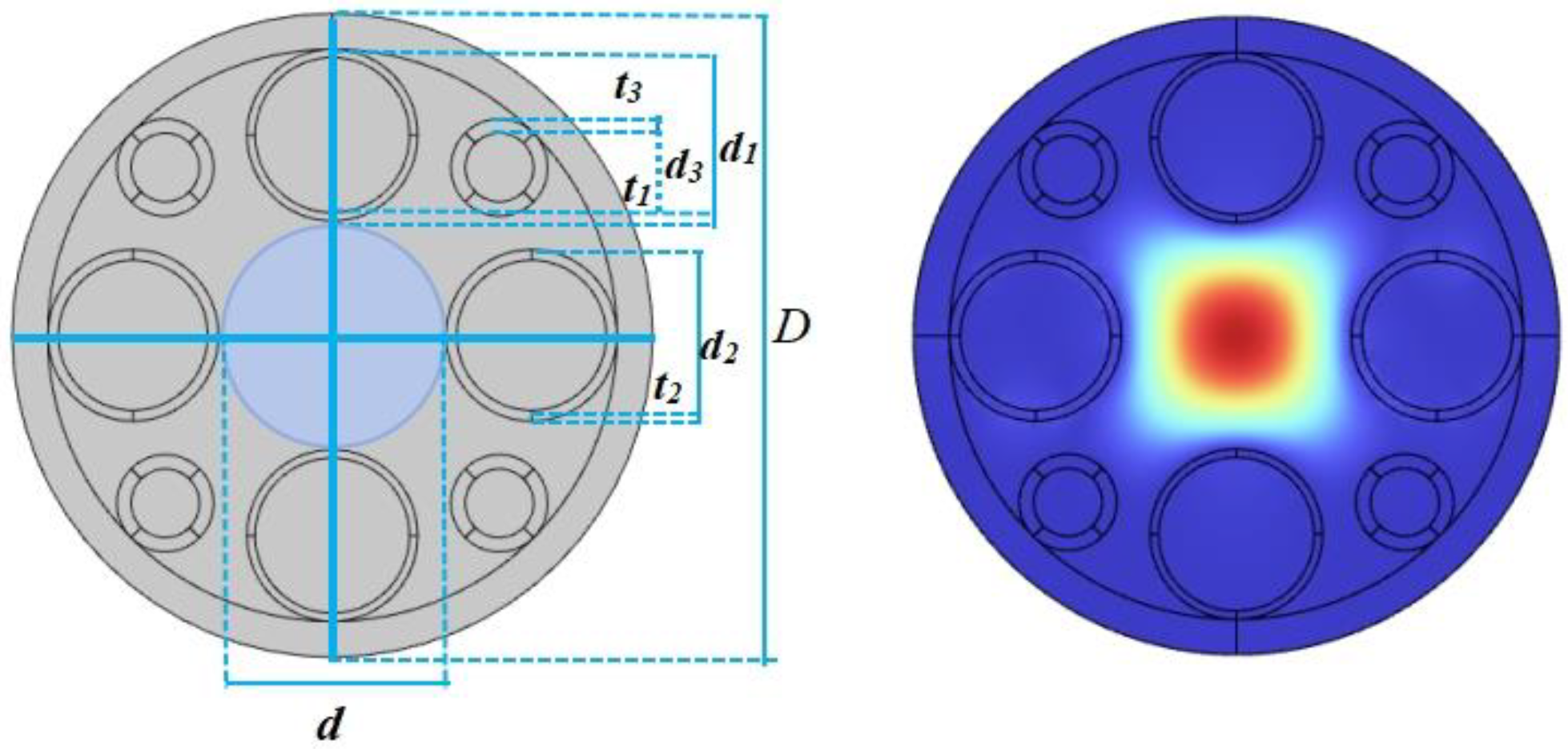
3.2. Optimized Design of Quasi-Symmetric Eight-Tube Hollow-Core Anti-Resonant Fiber Structure (S-EHARF)

Figure 2 shows the S-EHARF structure with an arrangement of equal diameters of cladding tubes in orthogonal directions. Firstly, considering that the curvature of the resonant tube has a large influence on the quantum spacing of the anti-resonant transmission band, through numerical simulation, d1, d2, d3 are determined as 24.00 μm, 24.00 μm, 13.80 μm, respectively, then the corresponding core diameter is determined as 38.70 μm, and the wall thicknesses of t1, t2, and t3, respectively, are selected, which should ensure that it is possible to produce the first anti-resonance band centered at approximately 19.35 μm.
In order to enhance the birefringence effect, this experiment takes three values of t1, such as 1.10 μm, 1.13 μm, 1.15 μm, etc, given that t2 and t3 are 1.50 μm and 2.00 μm, respectively. Numerical analysis is carried out using the finite element method to comprehensively examine the effects of the cladding tube wall thickness and the size of the inner diameter of the tube on the fiber loss and birefringence, and the results are shown in Table 1.
The attenuation constants in Table 1 are finite element method ad hoc solution terms whose physical units are defined as: optical signal attenuation per extended meter of fiber, and the same units as those defined for the limiting loss CL, but with a different characterization.
(1)
When t2 and t3 are 1.50 μm and 2.00 μm, respectively, and t1 is taken as 1.10 μm, 1.13 μm, and 1.15 μm, respectively, it can be seen that the birefringence coefficient B is larger and basically unchanged, which indicates that the effective refractive indices in the tube modes and in the core maintain a larger degree of transmission phase difference between them, which inhibits the coupling of the two modes and improves the birefringence efficiency, but the corresponding attenuation constant is larger.
(2)
When t1 and t3 are 0.16 μm and 1 μm, respectively, the birefringence coefficient B increases with t2, both due to the increased thickness difference between the two pairs of orthogonal resonance tube walls, which results in the enhanced asymmetry between the x-and y-directions.
(3)
The data in Table 1 show that among the S-EHARF series of structures, the optimal structure is S-EHARF-D with B = 0.7 × 10⁻⁴ and an attenuation constant of 5.01 dB/m.

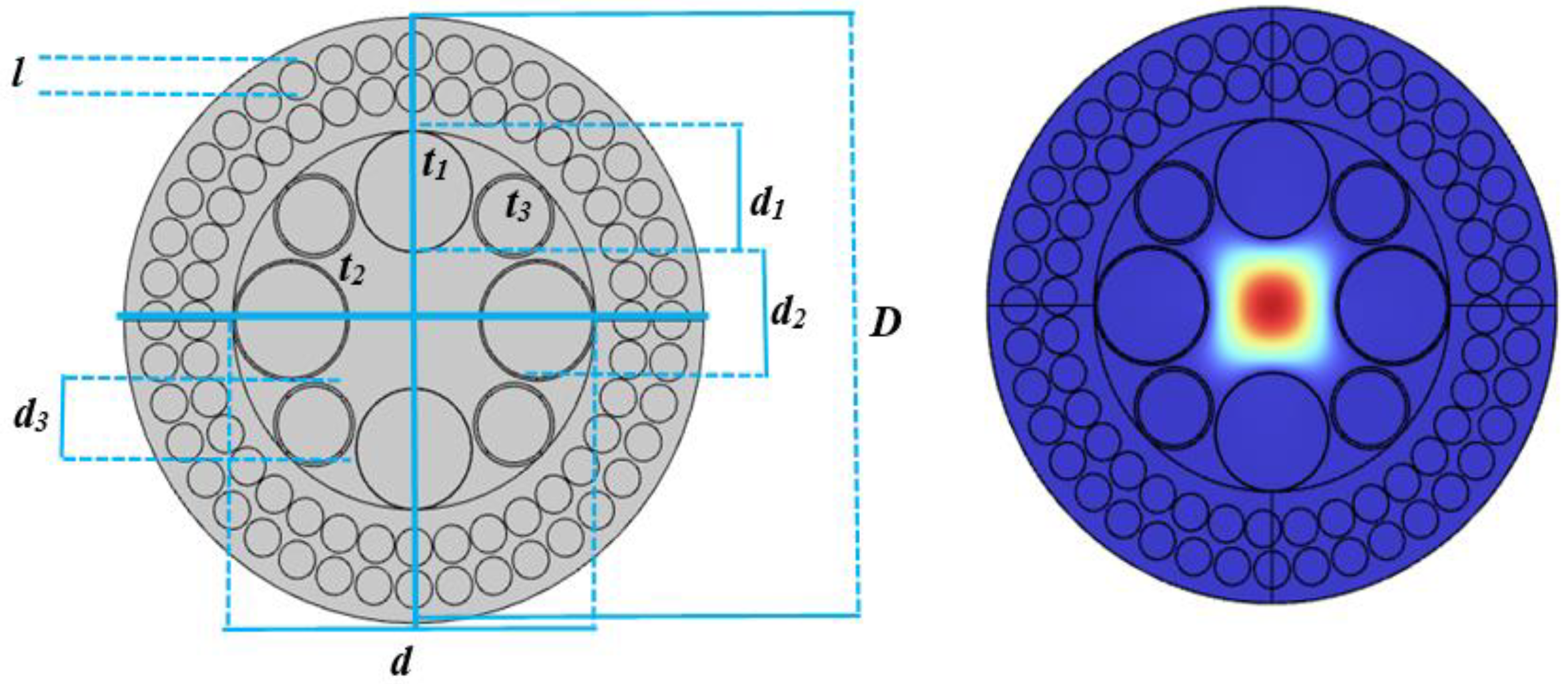
3.3. Optimized Design of Photonic Crystal Cladding Eight-Tube Quasi-Symmetric Empty Core Anti-Resonant Fiber (P-EHARF) Structure

Due to changing the photonic crystal structure parameters to form different lattice structures, the effective refractive index magnitude in the fiber cross-section space can be modulated to achieve low-loss and high-efficiency mode power output [20,21,22]. The photonic crystal is considered as an outer cladding layer to be incorporated into the design of the hollow-core anti-resonant birefringent structure, see Figure 3. The design idea follows the aforementioned basic principles.
The performance optimization design data of the fibers are provided in Table 2, from which it can be seen that the birefringence orders of magnitude of the four P-EHARF structures are up to, indicating that all four structures are high birefringence anti-resonant fibers.
(1)
The attenuation constant of P-EHARF-D is lower, when the diameter of the fundamental mode increases and the energy leakage decreases, and the symmetry of the structure is changed by fine-tuning t2, which has a greater impact on the loss performance.
(2)
The r3 and t2 of P-EHARF-D are reduced, but the birefringence performance and attenuation constant are also reduced. Due to the reduction in the two parameters, the inner cladding tube core mode overlap is reduced and the symmetry of the structure is changed, resulting in the improvement of the birefringence coefficient, and the mode coupling between the resonant tube and the core is strongly suppressed, reducing the loss.

3.4. Optimized Design of the Structure of Embedded Elliptical Tube Hollow Core Anti-Resonant Fiber (N-EHARF)

Adopting the arrangement of unequal diameters of resonant tubes in the orthogonal direction, considering that the curvature of the resonant tubes has a large influence on the quantum spacing of the anti-resonant transmission bands, r1, r2, and r3 are determined to be 19.00 μm, 28.00 μm, and 10.00 μm, respectively, and the corresponding wall thicknesses of the respective tubes are t1, t2, and t3, respectively, to ensure that the first anti-resonant transmission band centered around 19.35 μm can be produced, as shown in Figure 4.
In order to ensure the generation of birefringence effect and to reduce the fiber limiting loss. N-EHARF series of anti-resonant birefringent fibers, in addition to changing the structural parameters of the circular tube, the structural parameters of the nested ellipsoid have to be changed. The nested structure is established to obtain good single-mode characteristics in addition to increasing the anti-resonant layer to reduce optical leakage and suppressing cladding and core mode coupling. In this experiment, 1.10 μm, 1.13 μm, and 1.15 μm are taken for t1 under the optimization of t2 and t3 of 1.50 μm and 2.00 μm, respectively. Numerical simulations were carried out using the finite element method and the results are shown in Table 3.
(1)
N-EHARF-A~N-EHARF-C are all transverse long semiaxis embedded ellipsoids, and the long semiaxis of the embedded ellipsoids of the orthogonally oriented circular tubes are all transverse. And the ellipticity is 0.5 and the wall thickness is 1.43 μm. Among them, N-EHARF-A has the best birefringent system performance and N-EHARF-C has the best loss limiting performance.
(2)
N-EHARF-D and N-EHARF-E are orthogonal embedded ellipsoids, both with ellipticity e = 0.45 and wall thicknesses of t2. When other parameters of the two N-EHARFs are kept constant and only the ellipsoid wall thicknesses are varied to 1.14, the B is reduced to 0.4 × 10⁻⁴ but the attenuation constant is reduced to 10−2 order of magnitude.
(3)
The N-EHARF-F parameters are the same as in (2), and the wall thickness of this ellipse is 1.52 μm, at which time B = 1.20 × 10⁻⁴ and the attenuation constants are 1.12 dB/m and 0.22 dB/m, respectively. Comparing the results, the N-EHARF-F structure is the optimal structure.

4. Simulation Experiments and Discussion

4.1. Effect of Transverse Cladding Tube Wall Thickness t2, Wavelength λ on Limiting Loss CL

Figure 5 shows the loss profiles of the three optimized fibers with t2 at λ = 1.55 μm. Figure 5a shows that S-EHARF-D exhibits fluctuating changes in CL with increasing t2 in the range of 1.49 μm–1.63 μm, and the lowest loss is found at t2 = 1.52 μm, which is 1.04 × 10⁻³ dB/km; Figure 5b shows that P-EHARF-D exhibits an overall increase in CL when increasing in the range of t2 of 0.65 μm–0.80 μm The lowest loss occurs at t2 = 0.66 μm, which is 5.53 × dB/km, indicating that t1/t2 is larger when t1 is fixed, at which time the anti-resonance effect is stronger, and the structural forbidden-band effect of the outer cladding layer of the photonic crystal suppresses the mode coupling between the core and the cladding layer. Figure 5c shows that the fluctuation of the loss of the N-EHARF-F structure within t2 = 0.10 μm is obvious, indicating that this structure is sensitive to t2, and the CL is the lowest at t2 = 1.28 μm, which is 5.33 × 10⁻⁴ dB/km, due to the resonator tube multilayer reflective cascade effect.
Figure 6 shows limiting loss maps of the three optimized optical fibers operating at wavelengths in the range of 1.00 μm–2.00 μm. Table 4 lists their losses at λ = 1.31 μm, 1.55 μm, and 1.80 μm. Figure 6a reflects a large loss peak at λ = 1.48 μm for S-EHARF-D, indicating a significant resonance in the cladding tube here. Other than that, the other bands are in the smooth anti-resonance guiding band, and the losses are all less than 10−2 dB/km, but with a slight increase in wavelength, and the lowest loss is at λ = 1.22 μm, which is 1.36 × dB/km; Figure 6b shows that the loss of the P-EHARF-D structure with the wavelength increase basically shows a fluctuating upward trend, and the loss in the low wavelength band is less than 10−6 magnitude, and the lowest loss is at λ = 1.12 μm with a CL of 2.86 × 10⁻⁶ dB/km. Figure 6c shows that the limiting loss of the N-EHARF-F structure is less than dB/km in several major operating windows, indicating that the the elliptical inner sleeve can suppress the coupling between the tube mode and the core mode, resulting in lower confinement loss, and the lowest loss is 6.80 × 10⁻⁸ dB/km at λ = 1.09 μm.
The data in Table 4 show that the three fibers in this paper produce anti-resonance at 1.31 μm and 1.55 μm, and the CL is less than 10−3 dB/km order of magnitude, which is close to or even better than the results of the current research in this field.

4.2. Effect of Transverse Resonant Tube Wall Thickness t2, Wavelength λ on the Birefringence Coefficient B

Figure 7 shows the variation of birefringence coefficient B with t2 for the three optimized fibers at λ = 1.55 μm. As can be seen from Figure 7a, the birefringence coefficient of S-EHARF-D stays in the order of t2 in the range of 1.49 μm–1.59 μm at t2, indicating that the relative change of t2 is small, at which time the structural asymmetry is more stable, and the B reaches 7.15 × 10⁻⁴ at t2 = 1.58 μm; Figure 7b shows that the birefringence coefficient of P-EHARF-D is in the t2 of 0.64 μm–0.8 μm range, the birefringence shows one significant fluctuation, and the tight air-hole arrangement of the photonic crystal cladding leads to an increase in the spacing rate of change, resulting in the asymmetry of the local structure, which excites the increase in the birefringence coefficient, and the birefringence reaches a maximum of 1.25 × 10⁻⁴ at t2 = 0.75 μm; Figure 7c shows the N-EHARF-F structure reaches a maximum of 7.15 × 10⁻⁴ at t2 of 1.27 μm–1.37 μm range, the birefringence is more variable with the magnitude of B between 10−6–10−4 orders of magnitude, and the birefringence coefficient is increased compared with that of the P-EHARF-D structure. At t2 = 1.34 μm, the birefringence reaches a maximum of 1.60 × 10⁻⁴. Overall, among the three optimized fibers, the highest birefringence coefficient is found in S-EHARF-D.
Figure 8 shows the wavelength effect pattern on the birefringence performance of the first and third optimized fibers in the wavelength range of 1 μm–2 μm and the second optimized fiber in the wavelength range of 0.6 μm–2 μm after optimizing t1 and t2. The plots show that the birefringence of all three structures is obviously fluctuating, reflecting the periodicity of the coherent phase cancellation of the interference between the cladding and the empty core of the anti-resonant fiber. Figure 8a reflects that S-EHARF-D has all B below in the 1.20 μm–1.30 μm band, and the birefringence fluctuation is the largest in the 1.31 μm–2.00 μm band, indicating that the birefringence of this structure is the most sensitive to the wavelength change, and B is all higher than 10−4 and reaches the maximum value of 9.25 × 10⁻⁴ at the wavelength of 1.52 μm. The birefringence for the wavelength of 1.55 μm has a birefringence coefficient of 2.24 × 10⁻⁴; Figure 8b shows that the birefringence of P-EHARF-D is more stable in the near-infrared (NIR) band, which is between the orders of magnitude of 10−5–10−4, with a birefringence of 1.12 × 10⁻⁴ at a wavelength of 1.55 μm; Figure 8c shows that, in the NIR band of 1.00 μm–1.85 μm, both B are higher, and the birefringence at a wavelength of 1.75 μm reaches a maximum value of 4.87 × 10⁻⁴; λ has a birefringence coefficient of 1.35 × 10⁻⁴ at 1.55 μm.

4.3. Bending Characteristics of the Three Structures

Optical fibers often cannot avoid the problem of bending in the actual application process. Fiber bending affects the coupling of each mode in the fiber, which in turn causes the core mode leakage. At the same time, due to the change in the effective refractive index of the modes, which in turn generates bending loss. The bending characteristics of optical fibers are usually characterized by the following equation [14]:
n b = n x , y exp ( P / R b )
Rb is the bending radius, P is the bending direction of the fiber, n(x, y) is the effective refractive index of the straight fiber, and nb is the effective refractive index after bending.
Figure 9 shows the bending loss spectra of the three fibers, while the bending fundamental mode mode field diagrams of the three anti-resonance structured fibers are inserted separately. The bending direction of the first two structures is in the x-axis direction, and the bending direction of the third structure is in the y-axis direction. The polarization direction is shown in the mode field inset within the figure; nb and the bending radius are approximated as a linear incremental function; Figure 9a shows the bending loss characteristics of the S-EHARF-D structure, presenting a kind of symmetric curve centered at Rb = 30 mm, which shows that at Rb = 30 mm, the core mode and the tube mode undergo a strong coupling of the anticrossover type, and the loss peak occurs in the loss spectrum of the fiber [20], which is 5.80 dB/km and at bending radius of 28 mm, the bending loss is 2.10 × 10⁻³ dB/km, and the fiber core maintains single-mode low-loss transmission, which indicates that the S-EHARF-D structure has a strong bending resistance. Figure 9b shows that the P-EHARF-D bending loss is greatly affected by the bending radius, which is influenced by the photonic crystal cladding, and there are multiple peaks, and the bending loss is basically stabilized in the order of 10−3. At a bending radius of 35 mm, the bending loss is 3.10 × 10⁻³ dB/km. The lowest bending radius of this structure is relatively large, and the advantage of the photonic crystal cladding structure is that it is suitable for improving and enhancing the bending resistance of the internal resonator when the bending radius is large by flexibly regulating the cladding structure. However, the complex cladding structure tends to affect the deformation of the internal structure, so the bending radius is limited. This is also consistent with the structural characteristics of hollow-core anti-resonant fibers with photonic crystal cladding. Figure 9c shows that the core energy is basically not leaked after bending of the N-EHARF-F fiber, and the bending loss is stabilized at the order of 10−4 with the increase in the bending radius, which is superior to that of the previous two structures, and the bending loss is 1.10 × 10⁻⁴ dB/km at 35 mm.

4.4. Comprehensive Performance Analysis of Three Optimized Optical Fibers

According to the above simulation experiments and numerical calculations, the comprehensive performance of the three optimized structure anti-resonant optical fibers is shown in Table 5. A brief analysis is as follows:
  • The three kinds of optical fibers meet the high birefringence while the limiting loss is lower than 10−2 dB/km order of magnitude, and the lowest loss of N-EHARF-F reaches 3.42 × 10⁻⁵ at λ = 1.55 μm, which indicates that the elliptical inner-tube anti-resonant optical fiber realizes the ultra-low loss;
  • The birefringence coefficients of the three fibers at the wavelength of 1.55 μm reach, and the birefringence coefficient of S-EHARF-D reaches 2.24 × 10⁻⁴, which is valuable for the development of long-distance communication fibers;
  • The three fibers show good bending characteristics, the minimum bending radius is lower than 40 μm, and the bending radius of S-EHARF-D is 28 mm, and its structure is simple, which represents a good performance of low-loss high birefringence anti-resonance fiber.

5. Conclusions

In this paper, three kinds of low-loss, high-birefringence hollow-core anti-resonant fibers are optimally designed based on the eight-tube hollow-core anti-resonant structure, by focusing on regulating the transverse tube wall thickness t2, and numerical analyses of the performance of the three optimized optical fiber modes are performed using the finite element method. The results show that the birefringence coefficients at 1.55 µm are all up to, and the birefringence coefficient of S-EHARF-D is up to 2.24 × 10⁻⁴; the limiting losses are all lower than 10−2 dB/km, and the lowest loss of N-EHARF-F is 3.42 × 10⁻⁵; and the three kinds of optical fibers with a bending radius of more than 35 mm have losses lower than 10−3 dB/km, and the bending loss of S-EHARF-D is 2.1 × 10⁻³ dB/km when the bending radius is 28 mm. The three hollow-core birefringent anti-resonant fibers have their own characteristics and advantages, showing good low-loss and high-birefringent fiber performance. New development ideas and solutions are provided for low-loss bias-preserving mode transmission and corresponding polarization devices.
Due to the complex structure of the three structures of air resonator tubes designed in this paper, difficulties and limitations may be found in the current practical preparation techniques; however, with the emergence of various new structures of optical fibers, there have been many innovative preparation techniques effectively practiced, for example, in 2021, Julie Carcreff and others from the University of Rennes, France [24], printed for the first time, by using 3D printing technology, hollow-core vulcanized glass PCF preforms. It seems that 3D printing may be a trend in the future for PCF preform fabrication, and the advantage of 3D printing is that it can produce any complex structure, which is beneficial to the future development of fiber optics.

Author Contributions

Conceptualization, B.G. and D.C.; Data curation, B.G. and Z.H.; Funding acquisition, F.T.; Methodology, W.W.; Project administration, F.T.; Software, B.G. and S.C.; Supervision, F.T. and D.Z.; Validation, Y.Z. and Y.B.; Visualization, B.G.; Writing—original draft, B.G. and F.T.; Writing—review and editing, B.G. All authors have read and agreed to the published version of the manuscript.

Funding

This research was funded by Jilin Province Science and Technology Development plan, project (20240101110JC).

Institutional Review Board Statement

Not applicable.

Informed Consent Statement

Not applicable.

Data Availability Statement

Data are contained within the article.

Conflicts of Interest

The authors declare no conflicts of interest.

References

  1. Poggiolini, P.; Poletti, F. Opportunities and challenges for long-distance transmission in hollow-core fibres. J. Light. Technol. 2022, 40, 1605–1616. [Google Scholar] [CrossRef]
  2. Li, P.; Chen, W. Opportunities and challenges of long-haul communication with hollow-core anti-resonant fibers. Study Opt. Commun. 2023, 49, 1–8. [Google Scholar]
  3. Bradley, T.D.; Hayes, J.R.; Chen, Y.; Jasion, G.T.; Sandoghchi, S.R.; Slavík, R.; Fokoua, E.N.; Bawn, S.; Sakr, H.; Davidson, I.A. Record low-loss 1.3 dB/km data transmitting antiresonant hollow core fibre. In Proceedings of the 2018 European Conference on Optical Communication (ECOC), Rome, Italy, 23–27 September 2018; pp. 1–3. [Google Scholar]
  4. Russell, P.S.J.; Hölzer, P.; Chang, W.; Abdolvand, A.; Travers, J. Hollow-core photonic crystal fibres for gas-based nonlinear optics. Nat. Photonics 2014, 8, 278–286. [Google Scholar] [CrossRef]
  5. Liu, S.H.; Wang, Y.; Hou, M.X.; Guo, J.T.; Li, Z.H.; Lu, P.X. Anti-resonant reflecting guidance in alcohol-filled hollow core photonic crystal fiber for sensing applications. Opt. Express 2013, 21, 31690–31697. [Google Scholar] [CrossRef] [PubMed]
  6. Ding, W.; Wang, Y.Y.; Gao, S.F.; Wang, M.L.; Wang, P. Recent progress in low-loss hollow-core anti-resonant fibers and their applications. IEEE J. Sel. Top. Quantum Electron. 2019, 26, 1–12. [Google Scholar] [CrossRef]
  7. Han, Y.; Dong, T.T.; Qing, Y.; Song, P.; Zhu, W.Z.; Zhou, F.D.; Li, Z.R.; Wang, W.; Hou, L.t. Low loss hollow-core anti-resonant fiber in infrared band. J. Infrared Millim. Waves 2020, 39, 32–38. [Google Scholar]
  8. Zhang, X.; Dong, Z.H.; Yao, J.Y.; Wan, S.Q.; Wang, P. C+L-band 0.38 dB/km Ultra-low loss domestically produced nested tubular hollow-core anti-resonant optical fiber. Chin. J. Lasers 2022, 49, 1115002-1–1115002-5. [Google Scholar]
  9. Ding, W.; Wang, Y.Y. Hybrid transmission bands and large birefringence in hollow-core anti-resonant fibers. Opt. Express 2015, 23, 21165–21174. [Google Scholar] [CrossRef] [PubMed]
  10. Poletti, F. Nested antiresonant nodeless hollow core fiber. Opt. Express 2014, 22, 23807–23828. [Google Scholar] [CrossRef] [PubMed]
  11. Mousavi, S.A.; Sandoghchi, S.R.; Richardson, D.J.; Poletti, F. Broadband high birefringence and polarizing hollow core antiresonant fibers. Opt. Express 2016, 24, 22943–22958. [Google Scholar] [CrossRef] [PubMed]
  12. Wei, C.; Menyuk, C.R.; Hu, J. Polarization-filtering and polarization-maintaining low-loss negative curvature fibers. Opt. Express 2018, 26, 9528–9540. [Google Scholar] [CrossRef] [PubMed]
  13. Yerolatsitis, S.; Shurvinton, R.; Song, P.; Zhang, Y.; Francis-Jones, R.J.; Rusimova, K.R. Birefringent anti-resonant hollow-core fiber. J. Light. Technol. 2020, 38, 5157–5162. [Google Scholar] [CrossRef]
  14. Hui, Z.Q.; Yang, X.; Han, D.D.; Li, T.T.; Zhao, F.; Yang, Y.; Chen, S.G. High birefringence hollow-core anti-resonant terahertz photonic crystal fiber with ultra-low loss. J. Infrared Millim. Waves 2022, 41, 563–572. [Google Scholar]
  15. Hong, Y.F.; Gao, S.F.; Ding, W.; Zhang, X.; Jia, A.Q.; Sheng, Y.L.; Wang, P.; Wang, Y.Y. Highly Birefringent Anti-Resonant Hollow-Core Fiber with a Bi-Thickness Fourfold Semi-Tube Structure. Laser Photonics Rev. 2022, 16, 2100365. [Google Scholar] [CrossRef]
  16. Zhang, J.H.; Guo, N.; Zhu, W.Z.; Zhang, H.W.; Yang, P.; Pang, L. Optimized design of 351 nm low-loss, low-dispersion UV pure quartz anti-resonant hollow-core fiber. Tianjin Sci. Technol. 2022, 49, 36. [Google Scholar]
  17. Tan, F.; Yang, Q.; Huo, M.Y.; Zhou, J.; Zhou, D.C.; Xu, P.F. Structural design and properties study of rectangular lattice high polarization low-loss-Bi-Ge-Ga photonic crystal fiber. Intense Laser Part. Beams 2021, 33, 101002-1–101002-8. [Google Scholar]
  18. Wei, C.; Weiblen, R.J.; Menyuk, C.R.; Hu, J.J.A.i.O. Photonics. Negative Curvature Fibers; Optics and Photonics: Taoyuan City, China, 2017; Volume 9, p. 562. [Google Scholar]
  19. Zhang, Z.X.; Chen, W.; Tong, L.; Dai, W.W.; Liu, S.Q.; Zheng, Z.Q.; Ye, S.S.; Wang, Y.Y.; Jiang, W.H.; Gao, W.Q. Birefringence characterization of conformal negative curvature fibers. J. Quantum Electron. 2022, 39, 651. [Google Scholar]
  20. Wang, X.; Lou, S.Q.; Xing, Z. Loss characteristics of hollow-core photonic bandgap fibers. Infrared Laser Eng. 2019, 48, 103–108. [Google Scholar]
  21. Wan, B.W.; Zhu, L.Q.; Ma, X.; Li, T.S.; Zhang, J. Characteristic analysis and structural design of hollow-core photonic crystal fibers with band gap cladding structures. Sensors 2021, 21, 284. [Google Scholar] [CrossRef] [PubMed]
  22. Tan, F.; Xue, P.F.; Zhou, D.C.; Yang, Q.; Wang, L.L.; Song, X.Y. high nonlinearity Bi2O3-GeO2-Ga2O3 Photonic Crystal Fiber Performance Study. Laser Optoelectron. Prog. 2022, 59, 0306003. [Google Scholar]
  23. Xue, Y.B.; Li, H.S.; Liu, Y.J.; Wang, W.; Jiang, Y.C.; Ren, G.B.; Pei, L. Polarization-maintained anti-resonant hollow-core fiber. Laser Optoelectron. Prog. 2021, 58, 2326001. [Google Scholar]
  24. Li, J.H.; Jiang, H.M.; Xie, K. Development and current status of photonic crystal fiber preparation process. Sci. Technol. Innov. Appl. 2021, 11, 105–110, 114. [Google Scholar]
Figure 1. Schematic diagram of resonance and anti-resonance conditions.
Photonics 11 00675 g001
Figure 2. Eight-tube hollow-core anti-resonant fiber structure and fundamental mode mode field. D and d are the fiber diameter and core diameter, respectively; d1, d2, d3 are the diameter of the vertical tube, the horizontal tube diameter and the 45° axis diagonal cladding tube diameter, respectively; t1, t2, t3 are the thickness of the vertical tube to the tube wall, the horizontal tube wall thickness and the 45° axis diagonal cladding tube wall thickness, respectively.
Photonics 11 00675 g002
Figure 3. Photonic crystal cladding-octatube symmetric hollow-core anti-resonant fiber structure and fundamental mode mode field. D and d are the outer diameter and inner cladding diameter of the fiber, respectively; d1, d2, d3 are the diameter of the tube in vertical direction, the diameter of the tube in the horizontal direction and the diameter of the cladding tube diagonally at 45° axis, respectively; t1, t2, t3 are the thickness of the wall of the tube in the vertical direction, the thickness of the wall of the tube in the horizontal direction and the thickness of the cladding tube diagonally at 45°axis, respectively; and l is the diameter of the outer cladding small circle.
Photonics 11 00675 g003
Figure 4. Eight-tube embedded elliptical tube hollow core anti-resonant fiber structure and fundamental mode mode field. D and d are the outer and inner cladding diameters of the optical fiber, respectively; d1, d2, d3 are the diameters of the tube in the vertical direction, the diameter of the tube in the horizontal direction, and the diameter of the cladding tube diagonally at the 45° axis, respectively; t1, t2, t3 are the thicknesses of the wall of the tube in the vertical direction, the thickness of the wall of the tube in the horizontal direction, and the thickness of the wall of the cladding tube diagonally at the 45°axis, respectively; and a1, a2 are the lengths of the elliptical tubes in the vertical direction and the lengths of the elliptical tubes in the horizontal direction in terms of the lengths of the long axes of the elliptical tubes. b1, b2 are the length of the short axis of the vertical direction elliptic tube and horizontal direction elliptic tube, respectively.
Photonics 11 00675 g004
Figure 5. Influence law of t2 on the limiting loss of three optical fibers: (a) S-EHARF-D CL-t2 curve; (b) P-EHARF-D CL-t2 curve; (c) N−EHARF-F CL-t2 curve.
Photonics 11 00675 g005
Figure 6. Limiting loss maps of three optical fibers: (a) S-EHARF-D limiting loss-λ curve; (b) P-EHARF-D limiting loss-λ curve; (c) N-EHARF-F limiting loss-λ curve.
Photonics 11 00675 g006
Figure 7. Effect of t2 on the birefringence pattern of three optical fibers at λ = 1.55 µm: (a) S-EHARF-D bire fringence-t2 curve; (b) P-EHARF-D birefringence with-t2 curve; (c) N-EHARF-F birefringence with-t2 curve.
Photonics 11 00675 g007
Figure 8. Effect of wavelength on the birefringence law for the three fibers with the optimum t2 kept constant: (a) B-λ curve of S-EHARF-D; (b) B-λ curve of P-EHARF-D; (c) B-λ curve of N-EHARF-F.
Photonics 11 00675 g008
Figure 9. Bending loss-bending radius curves for three fibers: (a) BL-Rb curve of S-EHARF-D; (b) BL-Rb of P-EHARF-D; (c) BL-Rb curve of N-EHARF-F.
Photonics 11 00675 g009
Table 1. Optimized data of structural parameters of S-EHARF series (λ = 1.55 μm) Unit: μm.
Modelnumberr1r2r3t1t2t3B/10−4Attenuation Constant (dB/m)
S-EHARF-A12126.81.101.502.001.1838.10, 7.61
S-EHARF-B12126.81.131.502.001.1735.90, 6.80
S-EHARF-C12126.81.151.502.001.1739.00, 6.71
S-EHARF-D12128.60.160.7410.705.01, 1.60
S-EHARF-E12128.60.160.7611.206.60, 5.25
Table 2. Optimized data of structural parameters of P-EHARF series (λ = 1.55 μm) Unit: μm.
Modelnumberr1r2r3t1t2t3B/10−4Attenuation Constant (dB/m)
P-EHARF-A161611.040.1350.750.951.208.12, 7.34
P-EHARF-B161611.040.1350.750.9551.207.65, 8.21
P-EHARF-C161611.080.1350.750.9551.208.80, 8.62
P-EHARF-D161611.040.1350.740.9551.236.39, 4.53
Table 3. Optimized data of structural parameters of N-EHARF series (λ = 1.55 μm) Unit: μm.
Modelnumberr1r2r3t1t2t3Ellipticity ValueB/10−4Attenuation Constant (dB/m)
N-EHARF-A19281011.432.111.67, 1.820.40.64, 0.034
N-EHARF-B19281011.4321.67, 1.820.58.13, 0.099
N-EHARF-C19281011.4521.67, 1.820.60.13, 1.22
N-EHARF-D20.528100.331.4321.67, 1.820.70.22, 1.12
N-EHARF-E2028100.331.4321.67, 1.820.80.29, 3.29
N-EHARF-F2028100.331.43 (The elliptical wall thickness is 1.52)21.67, 1.820.9 (1.2)1.12, 0.22
Table 4. Limiting loss of three optical fibers in O + S + L + U communication bands.
Wavelength (μm)S-EHARF-D Limit Loss (dB/km)P-EHARF-D Limit Loss (dB/km)N-EHARF-F Limit Loss (dB/km)
1.315.73 × 10−45.66 × 10−61.59 × 10−4
1.551.10 × 10−22.32 × 10−43.42 × 10−5
1.802.20 × 10−21.80 × 10−42.68 × 10−4
Table 5. Performance data of three hollow-core anti-resonant birefringent fibers designed in this paper.
Structure TypeStructural CharacteristicsBirefringence B/10−4Limit Loss
dB/km
Minimum Loss dB/kmBending Characteristics dB/kmStudies by Other Scholars in Recent Years
S-EHARF-DQuasi-symmetric octa-hollow core tube claddingwavelength = 1.55 μm
B = 2.24 × 10⁻⁴
wavelength = 1.55 μm
CL = 1.10 × 10⁻²
wavelength = 1.22 μm
CL = 1.36 × 10⁻⁴
Rb = 28 mm
BL = 2.1 × 10⁻³
B = 1 × 10⁻⁴
CL = 20 dB/km
[12]
P-EHARF-DPhotonic crystal outer cladding combined with octal hollow core inner claddingWavelength = 1.55 μm
B = 1.12 × 10⁻⁴
wavelength = 1.55 μm
CL = 2.32 × 10⁻⁴
wavelength = 1.12 μm
CL = 2.86 × 10⁻⁶
Rb = 35 mm
BL = 3.1 × 10⁻³
B = 1.2 × 10⁻⁴
CL = 2dB/km, 1.3 dB/km
[23]
N-EHARF-FOrthogonal 4 cladding tubes embedded in elliptical tubeswavelength = 1.55 μm
B = 1.35 × 10⁻⁴
wavelength = 1.55 μm
CL = 3.42 × 10⁻⁵
wavelength = 1.09 μm
CL = 6.80 × 10⁻⁸
Rb = 35 mm
BL = 4.6 × 10⁻⁴
B = 9.1 × 10⁻⁵
CL = 185 dB/km
[15]
Disclaimer/Publisher’s Note: The statements, opinions and data contained in all publications are solely those of the individual author(s) and contributor(s) and not of MDPI and/or the editor(s). MDPI and/or the editor(s) disclaim responsibility for any injury to people or property resulting from any ideas, methods, instructions or products referred to in the content.

