Abstract
Temperature control is important in second harmonic generation (SHG) based on non-critical phase matching, which is widely used in the accelerator field to generate drive lasers. To further improve the stability of the drive laser for the DC-SRF photocathode electron gun at Peking University, a high-precision temperature control oven for lithium borate (LBO) crystals was developed. The oven’s structure was designed to minimize heat exchange with the external environment. The temperature control circuit uses a thermoelectric cooler to ensure the temperature stability of the sampling circuit. The program utilizes a cascaded proportional-integral-derivative and an anti-saturation integral algorithm to achieve high-precision temperature control. Experiments showed that fluctuation at the working temperature of the LBO crystal in this oven was within °C, corresponding to a root mean square (RMS) jitter of 0.003 °C, and the long-term power fluctuation of the 13.7 W green laser generated with SHG was less than 1%.
1. Introduction
The photocathode electron gun can produce high-quality electron beams suitable for large scientific facilities, such as free-electron lasers (FELs) and energy-recovery linear accelerators (ERLs) [1,2]. The photocathode generates electrons through the photoelectric effect, and the drive laser directly affects the quality of the electron beam [3]. The power stability of the drive laser determines the stability of the bunch charge, and the distribution of the laser determines the initial parameter of the electron bunch. Ensuring the energy and shape stability of the cathode drive laser is essential for obtaining high-quality electron beams. In a drive laser system, the laser amplification system usually works in the infrared band, while the widely used metal and semiconductor cathodes work in the green or ultraviolet band [4,5,6,7]. With the maturity of large-mode-area photonic crystal fibers, the power fluctuation of infrared high-power output can be controlled within 0.5% [4]. Therefore, an important source of the fluctuation is the second harmonic generation (SHG). The SHG process needs to meet the phase matching condition, for which both critical phase matching and non-critical phase matching (temperature matching) are used. The latter has low requirements for laser collimation, which can effectively avoid the walk-off effect and therefore improve laser beam quality [8,9,10]. However, the stability of harmonic generation is of high sensitivity to crystal temperature changes [11]. In their experiments with lithium borate (LBO) crystal, researchers at the RAL (Rutherford Appleton Laboratory) found that SHG efficiency significantly decreased due to thermal deposition without temperature control for the crystal. Using their self-developed temperature control oven, they achieved high-stability SHG output [12]. The drive laser system of the IHEP achieved stable 20 W green laser output for over an hour; they observed that output power fluctuated with temperature, and the fluctuation was about 2% [4]. Therefore, high-precision temperature control is a crucial aspect of obtaining highly stable laser output. In laser systems, thermoelectric coolers (TECs) are generally used for temperature control. The reason for this is that laser devices typically operate at room temperature, so the temperature controller needs to have both heating and cooling functions, with precision generally reaching a level of 0.005 °C [13,14]. As for nonlinear laser crystals, temperature control ovens are widely used in SHG, mainly including two types. The first type ensures that the entire crystal is at the same temperature. This type of oven is suitable for shorter crystals and has a simple structure, and various commercial products are available. To ensure temperature control accuracy, it requires direct contact between the bare crystal and the heating device or sensor. Due to the variability in crystal sizes, most commercial products cannot be directly used, and their temperature control precision is generally around 0.1 °C, so many laboratories develop their own temperature control ovens according to their specific needs. Temperature control precision is generally around 0.1 °C or 0.01 °C [12,15,16]. The other type of oven is primarily designed for long crystals. It can create a temperature gradient along the laser transmission direction of the crystal, compensating for phase mismatch caused by uneven heating in long crystals, thus improving SHG efficiency. This type of oven requires a complex structure with multiple temperature sensors and heaters, leading to complex software design [17,18,19]. All the above designs highlight the importance of a high-precision and high-stability temperature control oven for the stability of SHG.
We have been developing a high performance photocathode electron gun, DC-SRF [20], which demands high quality and a stable laser system. The previous drive laser system produced a 0.74 W green laser with a SHG efficiency of 42% and a power fluctuation of 2.2%. To achieve higher power and a more stable green laser output, we developed a multifunctional, highly stable laser system named PULSE (Peking University drive laser system for high-brightness electron source). The new system, for which a temperature control oven for LBO crystals was developed, has achieved a SHG power fluctuation of 0.7%. This paper presents the hardware and software designs of the oven, together with some important experimental results.
2. Hardware and Software Design
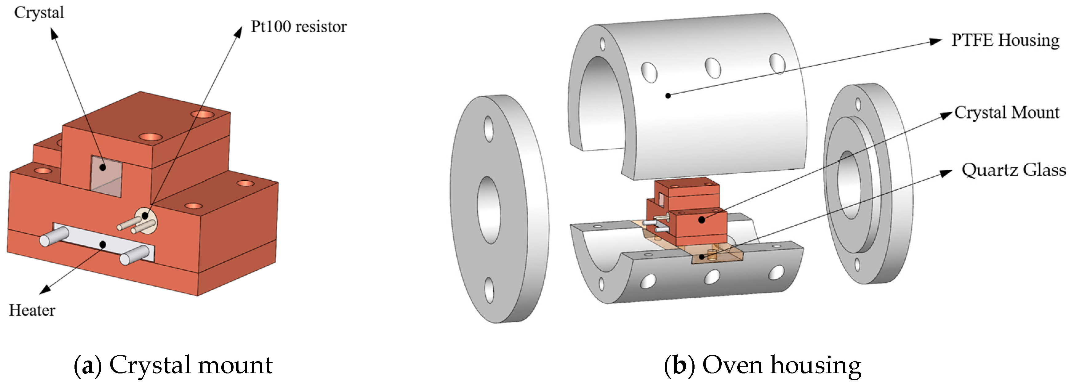
The SHG process in the PULSE uses a mm LBO crystal, for which we designed a dedicated oven, which comprises a crystal mount (Figure 1a) and an oven housing (Figure 1b). The crystal mount consists of three gold-coated copper pieces, which are applied to fix the crystal, the Pt100 resistor, and the ceramic heater. Between the crystal and copper blocks indium films are used to prevent damage caused by mechanical stress and to make the heating of the crystal more uniform. For the oven housing design, heat exchange between the crystal mount and the external environment needed to be minimized. Therefore, a polytetrafluoroethylene (PTFE) cylindrical housing was used, which has small holes on both ends for laser beam passage. The housing was mechanically jointed to the crystal mount by a quartz glass sheet with low thermal conductivity (1.340 W/(m·K)). The overall structure is shown as Figure 1.

Figure 1.
Structure of the temperature control oven. (a) Crystal mount, three gold-coated copper pieces applied to fix the crystal, Pt100 resistor, and ceramic heater; (b) Oven housing, including cylindrical PTFE housing, crystal mount, and quartz glass sheet.
In the circuit design, a four-wire Pt100 resistor is used as a temperature sensor, with an analog-to-digital converter (ADC) chip for data acquisition. Data are handled using a microcontroller, which then generates the pulse width modulation (PWM) output. After a half bridge rectification and an LC filter circuit, the PWM signal is used to drive the ceramic heating plate, as shown in Figure 2.
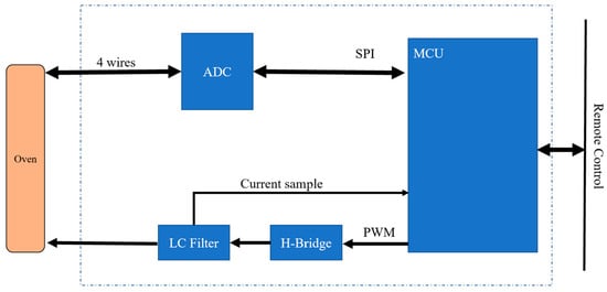
Figure 2.
The topology of the control circuit.
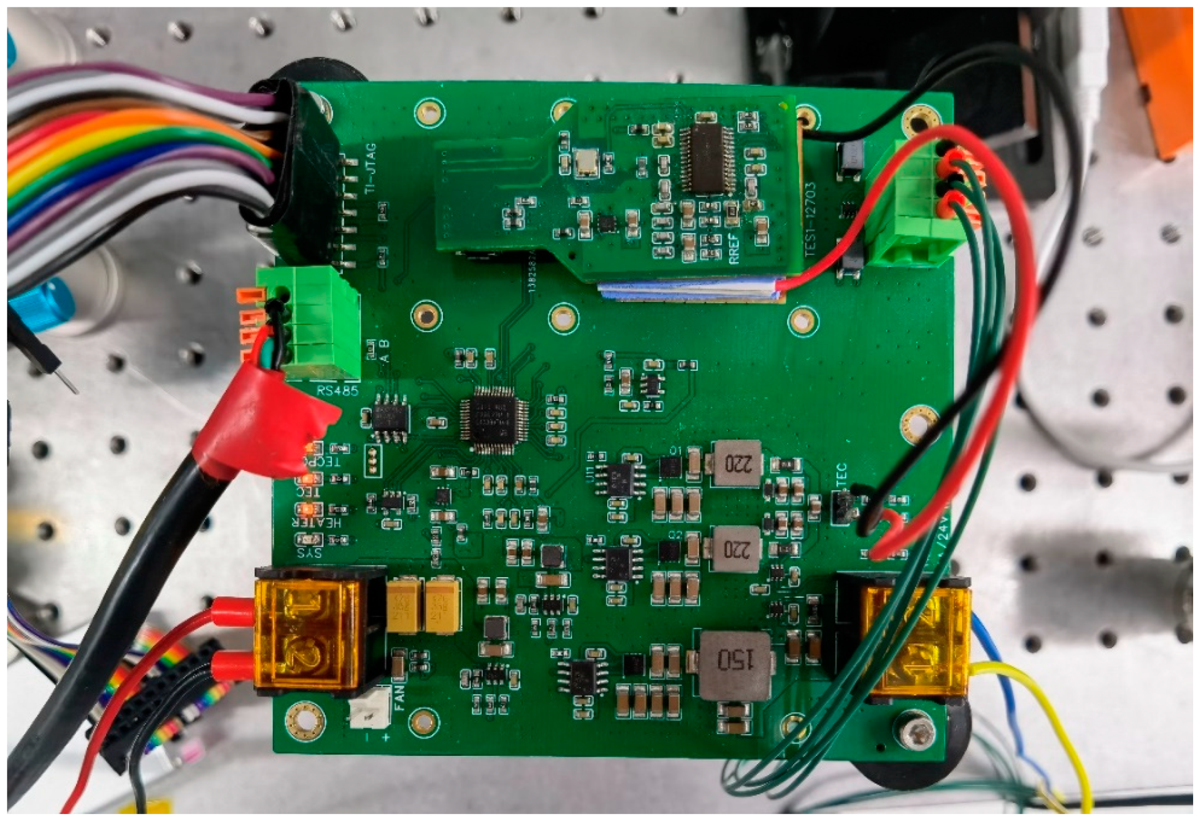
To diminish sampling errors caused by temperature variation, a TEC is used to control the ADC chip’s temperature, maintained at °C. Considering that large currents on the circuit may interfere with the temperature sampling signal, the ADC sampling circuit was designed on a separate sub-board that was physically isolated from the main board, with signal exchange through pin headers. The TEC was placed below the sub-board, with heat conducted through copper pieces and thermal silicone pads to the large copper coating area on the main board. Figure 3 shows the whole control circuit board.
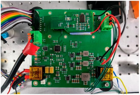
Figure 3.
Image of the circuit board.
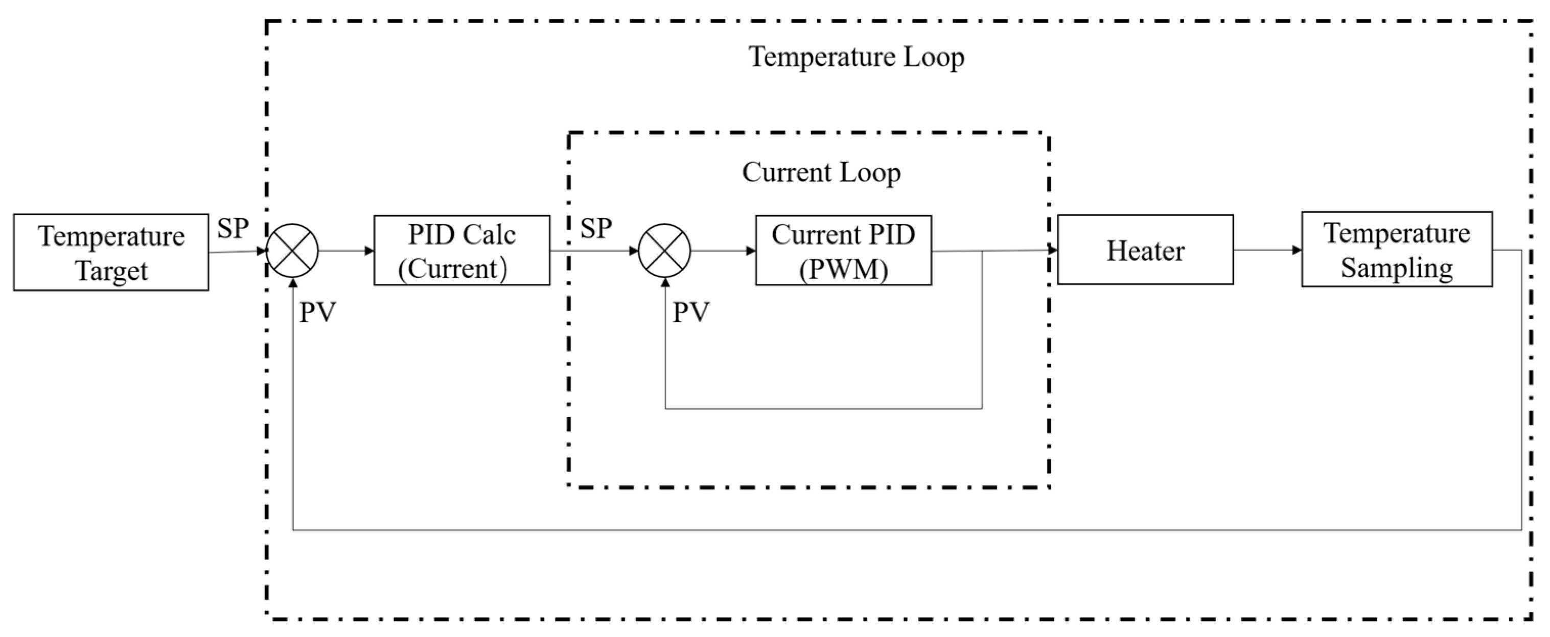
The oven has significant thermal inertia and time lag, posing high demands on temperature regulation and maintenance. The control program uses the cascaded PID scheme, as shown in Figure 4, both in the oven and the TEC’s control.
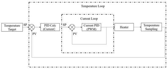
Figure 4.
Cascade PID processing flow.
The temperature loop is responsible for temperature sampling and the calculation of the error between set and sampled values. The temperature probe utilizes a Pt100 resistor with AA-grade accuracy. Its resistance has a quadratic dependency on the temperature,
within the range from 0 °C to 850 °C, where t is the temperature in Celsius, is the resistance at 0 °C, and the coefficients are . The resistor is measured by a 32-bit ADC, ADS1263, which has an internal high-precision constant current source outputting 2 mA as the drive current (IDAC in Figure 5). When the current passes through the resistor, its voltage drop is obtained by the ADC, and the resistance is calculated. The corresponding temperature is then solved using the Newton–Raphson iterative method. The sampled temperature and the set temperature are analyzed in a PID process, and the result serves as the set value of the current loop. In this process, the stability of the ADC’s reference voltage is the key to ensuring sampling accuracy. The reference voltage, having a value of 2 V, is the voltage drop across a precise reference resistor R4, which is in series with the sampling resistor. The reference resistor’s error is 0.01%, while the drive current error is 0.7%, and accordingly, the reference voltage error is about 0.7%. And to reduce the impact of electromagnetic interference, we designed the filter network shown in Figure 5.
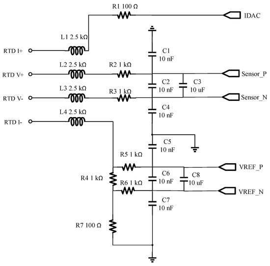
Figure 5.
Sampling circuit schematic.
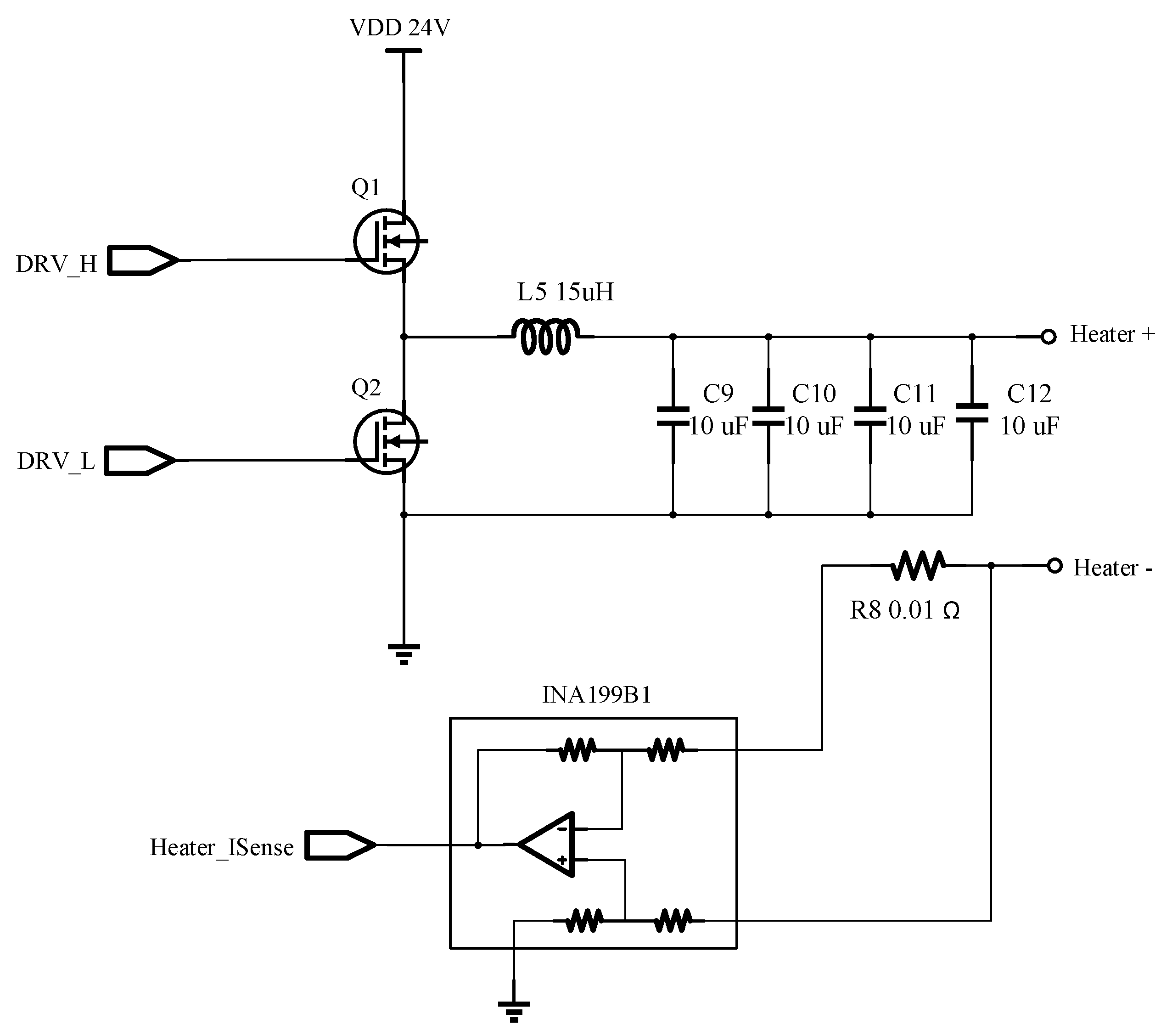
The function of the current loop is to sample and adjust the output current. A 10 sampling resistor is connected in series to the output circuit to convert the output current into voltage, which is then amplified by the INA199B1 and sampled by an integrated ADC in the microcontroller in sequence. The output current calculated from the sampled voltage is compared with the set value from the temperature loop, and the error is handled in the PID process. According to the PID results, the duty cycle of the PWM output is modulated, and then the diode driver chip LM5104 is controlled by the PWM signal to work with the LC filter circuit to complete the drive of the heater, as shown in Figure 6. To achieve high-precision current control, the sweep frequency of the current loop needs to be as high as possible. For this purpose, the microcontroller chip adopts TMS320F28027, of which the PWM’s trip zone interrupt automatically triggers the ADC sampling, and the end of conversion (EOC) interrupt of the ADC immediately updates the duty cycle of the PWM output. A high-speed current loop at a frequency of 50 kHz is therefore achieved. Relatively, the sweep frequency of the temperature loop is set to 400 Hz, ensuring that the current reaches a steady state before the set value changes. In addition to the above cascaded PID algorithm, an anti-saturation integral algorithm was adopted to adjust the PID integral limit, so as to avoid device damage due to excessive heating and reduce overshoot, stabilizing the system faster.
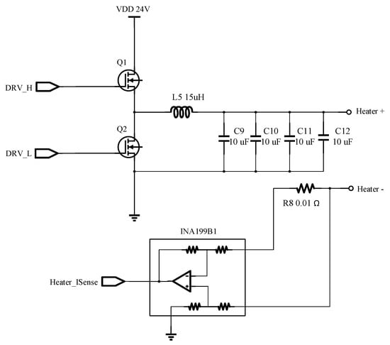
Figure 6.
Half-bridge drive circuit of the heater.
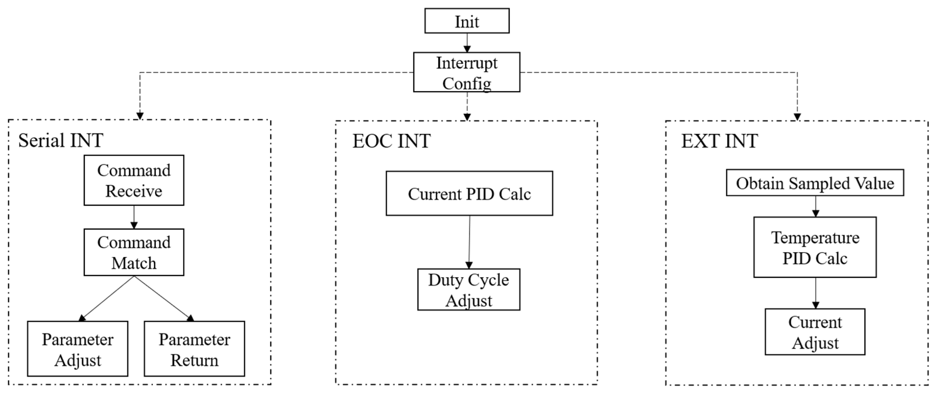
To facilitate remote control, a set of Standard Commands for Programmable Instruments (SCPI) was developed. The serial port reception interrupt receives upper computer commands for parameters adjustment and temperature measurement value readback, allowing easy integration into the Experimental Physics and Industrial Control System (EPICS). The overall control structure is shown in Figure 7.
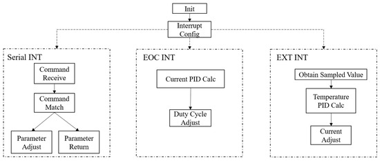
Figure 7.
The control program’s structure.
3. Results and Discussion
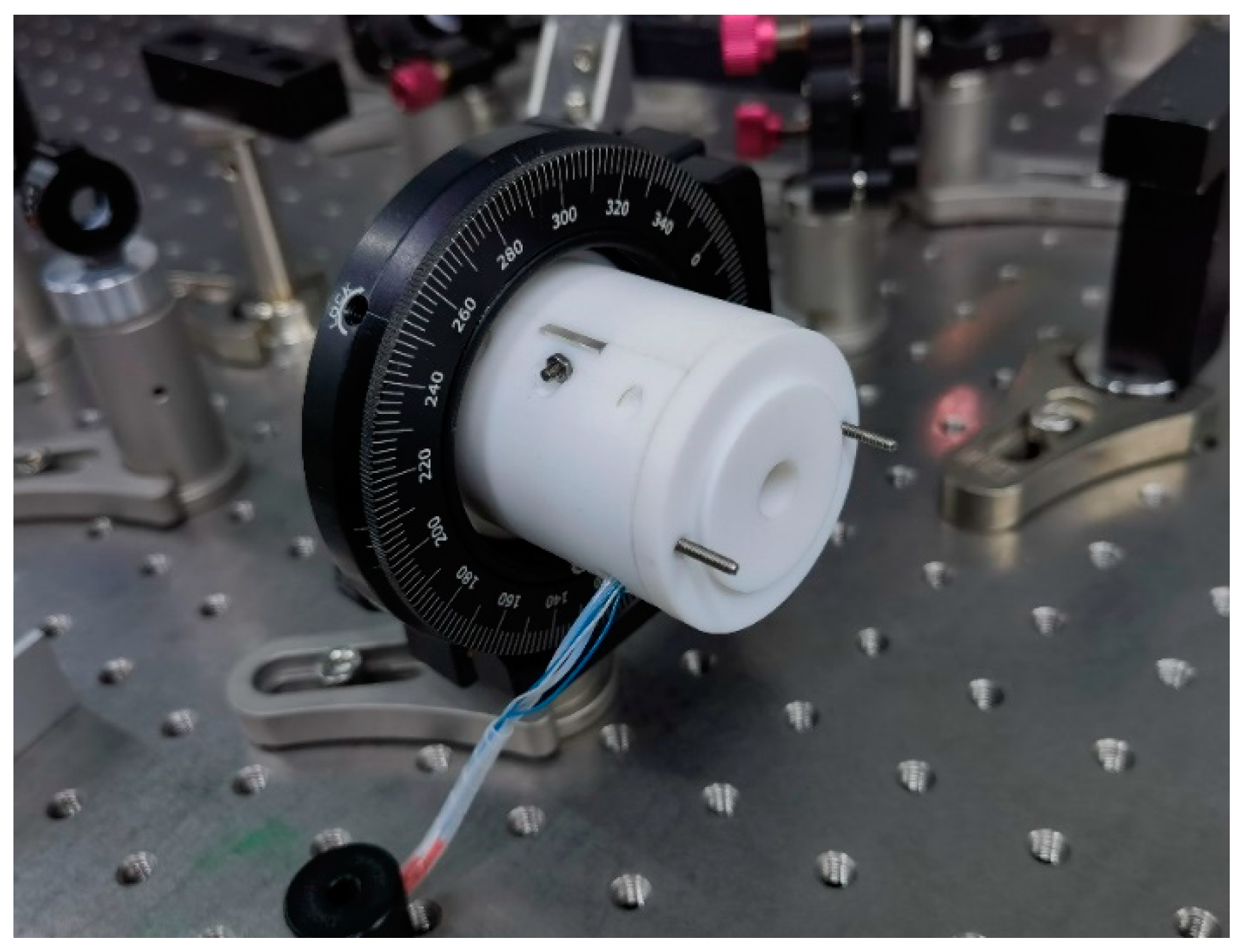
The main oscillator of the PULSE is a femtosecond mode-locked laser from Menlo Systems, with a repetition rate of 81.25 MHz. The laser output from the main oscillator is filtered, amplified, and compressed by a grating pair, producing a maximum infrared power of 99.3 W with a fluctuation of less than 0.4%. The infrared laser has a central wavelength of 1029.5 nm, with a spectral width of 2.26 nm (FWHM) and a pulse duration of 5.28 ps. It is focused by a convex lens into the LBO crystal for SHG, and the crystal oven is finally fixed on a rotation mount, as shown in Figure 8.
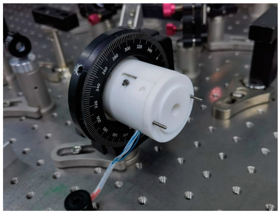
Figure 8.
Image of the temperature control oven.
Before a laser experiment, PID parameters need to be adjusted. The PID control function can be expressed mathematically as
where , , and denote the coefficients for the proportional, integral, and derivative terms, respectively. In a PID algorithm, determines the sensitivity of the system. A small leads to an insufficient response to temperature changes, while a large affects the system’s dynamic range. can form an independent parameter that can be adjusted separately. In this design, the temperature loop frequency is 400 Hz. Due to the slow temperature response of the heater, when the set temperature and the actual temperature are significantly different, the error integral can rise rapidly, causing the heater current to increase quickly. To avoid damaging the device, must be kept sufficiently small. At the same time, to ensure that the integral term is effective, the upper limit of the error integral needs to be adjusted to be sufficiently large. Similarly, can also be regarded as an independent parameter , which is responsible for controlling potential temperature changes and is usually adjusted after the system has stabilized. After careful tuning, and were determined to be 0.19, , and 0.12, respectively, and the upper limit of the error integral was set to .
The LBO crystal has a cut angle of 12° and a phase-matching temperature of 70 °C. By rotating the crystal angle, we can change its phase-matching temperature. When adjusting the crystal installation position, we found that the SHG efficiency was highest when the crystal temperature was set to 101 °C, and the system was relatively stable at this temperature. Therefore, in subsequent experiments, the oven was set to this temperature. The oven’s tests were first conducted without laser input. The temperature of the oven can reach a stable state within 3 min; in the beginning, there was an overshoot of about 6 °C (Figure 9a). In the subsequent 7 h test, the temperature of the oven could be maintained within the range of °C, with an RMS fluctuation of 0.003 °C (Figure 9b), while the temperature of the ADC chip was maintained at °C (Figure 9c).
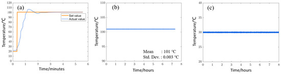
Figure 9.
Experimental test results: (a) temperature changes at startup; (b) temperature monitoring for 7 h after it stabilized; (c) temperature monitoring of ADC sub-board during the experiment.
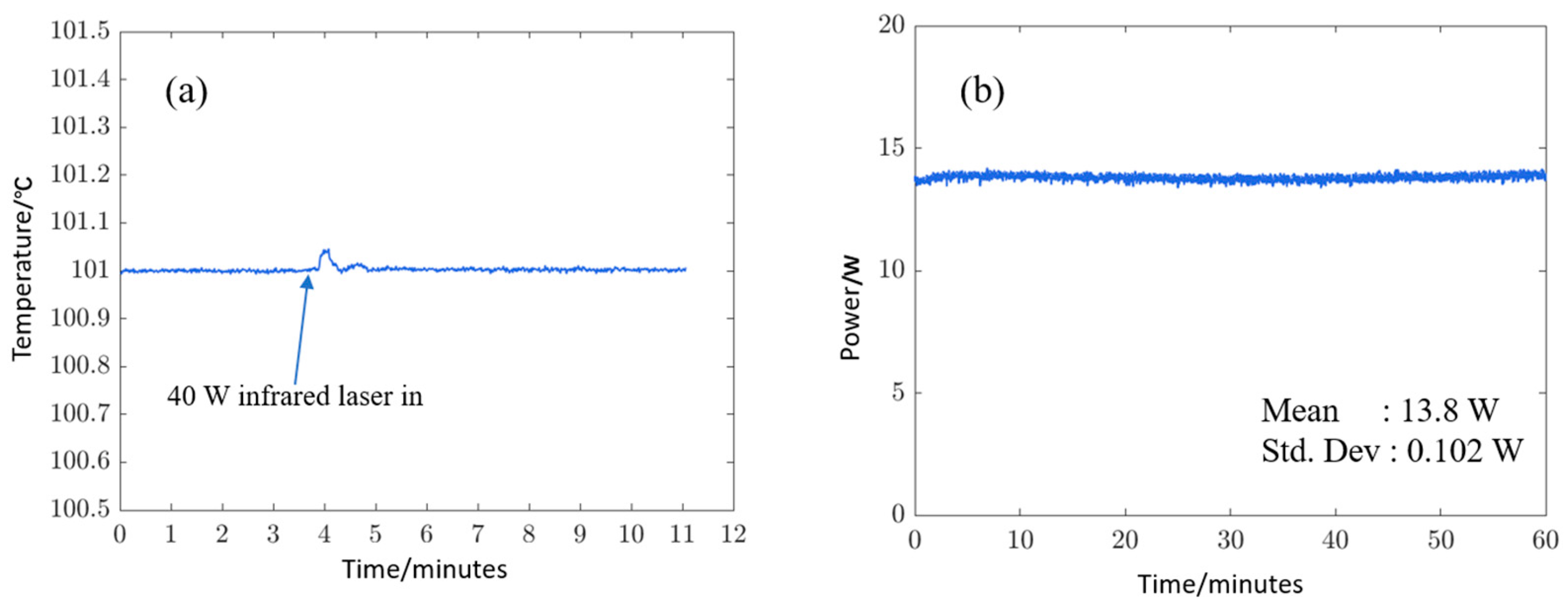
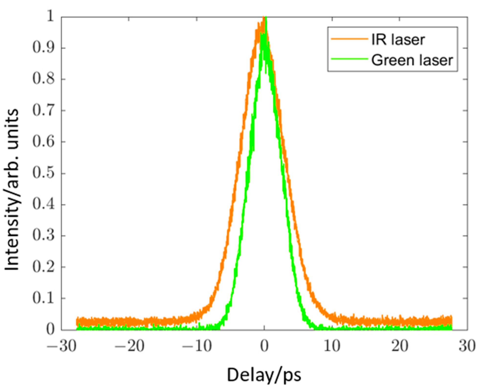
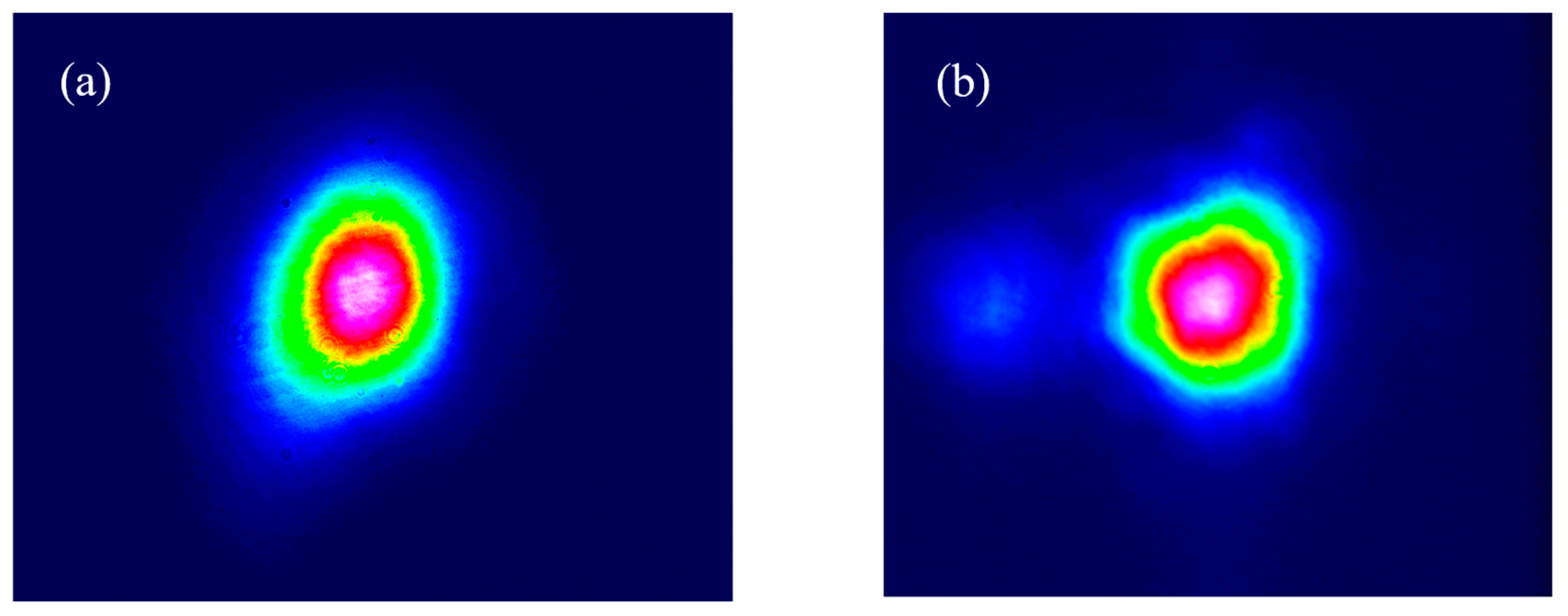
According to the requirements of DC-SRF operation, the laser system needed to operate in a mode with an 81.25 MHz repetition rate to achieve the high beam intensity power the infrared laser needs to set at 40 W. After the oven reached its set temperature, we increased the infrared laser power to 40 W. It was observed that as the laser passed through, the LBO was heated with a temperature overshoot less than 0.1 °C. However, within two minutes, the oven could adjust and return to a stable state, as shown in Figure 10a. In this condition, we measured the stability of the green laser’s power. Within the one-hour monitoring period, the power of the infrared laser before SHG was 39.7 W, and the power of the generated green laser was 13.8 W, with an efficiency of 34.7%. The power fluctuation over one hour was 0.7%, as shown in Figure 10b. And as shown in Figure 11, the full width at half maximum (FWHM) of the laser pulse before and after SHG was 5.28 ps and 3.92 ps, respectively. The laser beam’s shapes are shown in Figure 12, indicating that the SHG process did not introduce beam distortion.

Figure 10.
Laser stability test results: (a) temperature response of oven when 40 W infrared laser passed through; (b) SHG output power stability monitoring results over 1 h.

Figure 11.
Autocorrelation results of IR and green lasers.

Figure 12.
Beam shapes (a) before and (b) after SHG.
After the oven was tuned, we conducted a beam experiment with continuous wave operation for about 6 h on the DC-SRF photocathode electron gun [20]. The drive laser used in the experiment was a green laser generated by the SHG module. During the 6 h experiment, the oven maintained the temperature within the range of °C, with an RMS fluctuation of 0.0025 °C, as shown in Figure 13a, providing favorable conditions for the experiment. This was the longest experiment with a laser passing through the oven. When there was no laser passing through, the oven could also achieve a long-term stable temperature. We captured 9-day operating results from the oven without conducting laser experiments, as shown in Figure 13b. During this extended period, the oven was able to maintain the temperature within the range of °C, with an RMS fluctuation of 0.0025 °C.
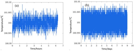
Figure 13.
Long-term operation results: (a) 6 h results with laser passing through; (b) 9-day results without laser passing through.
This oven has been continuously operating in the laser system for over a year without any failures, proving its reliability. Compared to commercial products, this oven can use specific mount structures designed for crystals of different sizes and shapes, offering broad applicability. For example, in addition to the LBO crystal, our laser system also uses 8 YVO4 crystals for longitudinal coherent shaping of the laser, which require temperature stability. The crystals are packaged in cylinders with a diameter of 10 mm and a length of 10 mm. We simply modified the mount structure to make the oven suitable for these crystals [21]. In addition, compared to commercial products or the work of others [12,15,16], this oven achieves extremely high temperature control stability, even with high-power lasers passing through, reaching a worldwide advanced level.
4. Conclusions
We developed a laser crystal oven with high-precision temperature control. Through careful hardware and software design, the oven can accurately control the laser crystal’s temperature with a fluctuation within °C, corresponding to an RMS value of 0.003 °C. Using this oven, highly stable SHG has been achieved, with a power fluctuation of about 0.7% at an average power of 13.7 W. And, during long periods operation without laser load and with laser load, the oven can maintain highly stable temperature control. This lays a good foundation for generating high-quality electron beams with our laser driven photocathode electron gun. In addition, after simple modification, this oven is also suitable for other laser crystals, like YVO4, which require high-precision temperature control. In conclusion, this temperature control oven is highly reliable and scalable, providing an effective solution for the temperature control of laser crystals.
Author Contributions
Conceptualization, L.F., H.X. and X.Z.; methodology, X.Z. and H.X.; software, X.Z. and L.F.; formal analysis, X.Z.; investigation, X.Z., H.X., Z.L. and T.W.; provision of study materials, J.X. and S.Q.; writing—original draft preparation, X.Z.; writing—review and editing, S.H. and H.X. All authors have read and agreed to the published version of the manuscript.
Funding
This study was funded by the National Key Research and Development Program of China, grant number 2017YFA0701001; the National Natural Science Foundation of China, grant number 12175251; and the State Key Laboratory of Nuclear Physics and Technology, Peking University, grant numbers NPT2020KFY15 and NPT2022ZZ01.
Institutional Review Board Statement
Not applicable.
Informed Consent Statement
Not applicable.
Data Availability Statement
Original contributions of this study are included in this article; further inquiries can be directed to the corresponding author.
Conflicts of Interest
The authors declare no conflicts of interest.
References
- Stephan, F.; Krasilnikov, M. Synchrotron Light Sources and Free-Electron Lasers. In High Brightness Photo Injectors for Brilliant Light Sources; Springer: Cham, Switzerland, 2014; pp. 1–38. ISBN 978-3-319-04507-8. [Google Scholar]
- Xiang, R.; Arnold, A.; Lewellen, J.W. Superconducting Radio Frequency Photoinjectors for CW-XFEL. Front. Phys. 2023, 11, 1166179. [Google Scholar] [CrossRef]
- Zhou, F.; Brachmann, A.; Emma, P.; Gilevich, S.; Huang, Z. Impact of the Spatial Laser Distribution on Photocathode Gun Operation. Phys. Rev. Spec. Top.—Accel. Beams 2012, 15, 090701. [Google Scholar] [CrossRef]
- Xu, H.; Xu, J.; Li, X.; Feng, L.; Huang, S.; Li, J. High Power Drive Laser System for Photocathode at IHEP. Opt. Express 2021, 29, 29550. [Google Scholar] [CrossRef] [PubMed]
- Zhang, S.; Hardy, D.; Neil, G.; Shinn, M.D.; Lab, J.; News, N. Characterization and Performance of a High-Power Solid-State Laser for a High-Current Photocathode Injector. In Proceedings of the 27th International Free Electron Laser Conference, Stanford, CA, USA, 21–26 August 2005; pp. 351–354. [Google Scholar]
- Ito, I.; Nakamura, N.; Honda, Y.; Kobayashi, Y.; Torizuka, K.; Yoshitomi, D. Development of an Yb-Doped Fiber Laser System for an ERL Photocathode Gun. In Proceedings of the IPAC10, Koyoto, Japan, 23–28 May 2010; Volume 100523, pp. 2141–2143. [Google Scholar]
- Akemoto, M.; Arakawa, D.; Asaoka, S.; Cenni, E.; Egi, M.; Enami, K.; Endo, K.; Fukuda, S.; Furuya, T.; Haga, K.; et al. Construction and Commissioning of the Compact Energy-Recovery Linac at KEK. Nucl. Instrum. Methods Phys. Res. Sect. Accel. Spectrometers Detect. Assoc. Equip. 2018, 877, 197–219. [Google Scholar] [CrossRef]
- Mao, H.; Fu, F.; Wu, B.; Chen, C. Noncritical Quasiphase-Matched Second Harmonic Generation in LiB3O5 Crystal at Room Temperature. Appl. Phys. Lett. 1992, 61, 1148–1150. [Google Scholar] [CrossRef]
- Jiang, X.; Ji, L.; Liu, D.; Tang, S.; Zhu, B.; Lin, Z. Noncritically Phase-Matched Fourth-Harmonic Generation of Nd:Glass Lasers and Design of Final Optics Assembly. Appl. Opt. 2016, 55, 4132–4138. [Google Scholar] [CrossRef] [PubMed]
- Ji, S.; Wang, F.; Zhu, L.; Xu, X.; Wang, Z.; Sun, X. Non-Critical Phase-Matching Fourth Harmonic Generation of a 1053-Nm Laser in an ADP Crystal. Sci. Rep. 2013, 3, 1605. [Google Scholar] [CrossRef] [PubMed]
- Zhai, N.; Li, C.; Xu, B.; Bai, L.; Yao, J.; Zhang, G.; Hu, Z.; Wu, Y. Temperature-Dependent Sellmeier Equations of IR Nonlinear Optical Crystal BaGa4Se7. Crystals 2017, 7, 62. [Google Scholar] [CrossRef]
- Phillips, J.P.; Banerjee, S.; Ertel, K.; Mason, P.; Smith, J.; Butcher, T.; De Vido, M.; Edwards, C.; Hernandez-Gomez, C.; Collier, J. Stable High-Energy, High-Repetition-Rate, Frequency Doubling in a Large Aperture Temperature-Controlled LBO at 515 Nm. Opt. Lett. 2020, 45, 2946. [Google Scholar] [CrossRef] [PubMed]
- Li, N.; Qiu, X.; Wei, Y.; Zhang, E.; Wang, J.; Li, C.; Peng, Y.; Wei, J.; Meng, H.; Wang, G.; et al. A Portable Low-Power Integrated Current and Temperature Laser Controller for High-Sensitivity Gas Sensor Applications. Rev. Sci. Instrum. 2018, 89, 103103. [Google Scholar] [CrossRef] [PubMed]
- Kehl, F.; Cretu, V.F.; Willis, P.A. Open-Source Lab Hardware: Driver and Temperature Controller for High Compliance Voltage, Fiber-Coupled Butterfly Lasers. HardwareX 2021, 10, e00240. [Google Scholar] [CrossRef] [PubMed]
- Gilevich, S.; Alverson, S.; Carbajo, S.; Droste, S.; Edstrom, S.; Fry, A.; Greenberg, M.; Lemons, R.; Miahnahri, A.; Polzin, W.; et al. The LCLS-II Photo-Injector Drive Laser System. In Proceedings of the Conference on Lasers and Electro-Optics, San Jose, CA, USA, 10–15 May 2020; Optica Publishing Group: San Jose, CA, USA, 2020; p. SW3E.3. [Google Scholar]
- Yuan, J.; Yang, H.; Ouyang, Y.; Zhou, S.; Wang, Z.; Cheng, W. High Efficiency High Beam Quality Third Harmonic Generation of Hundreds Femtosecond Laser by Employing a Delay Line and LiB3O5 Crystals. Opt. Mater. 2023, 145, 114472. [Google Scholar] [CrossRef]
- Shahidani, M.; Ghavami Sabouri, S.; Khorsandi, A. Temperature Gradient Engineered to Maintain Pulse Shape and Efficiency of a 532 Nm Picosecond Second-Harmonic Generation. Appl. Phys. B 2020, 126, 89. [Google Scholar] [CrossRef]
- Sabouri, S.G.; Khorsandi, A. Thermal Dephasing Compensation in High-Power and High-Repetition-Rate Second-Harmonic Generation Using Spillover Loss. JOSA B 2016, 33, 1640–1648. [Google Scholar] [CrossRef]
- Rozenberg, E.; Arie, A. Broadband and Robust Adiabatic Second-Harmonic Generation by a Temperature Gradient in Birefringently Phase-Matched Lithium Triborate Crystal. Opt. Lett. 2019, 44, 3358–3361. [Google Scholar] [CrossRef] [PubMed]
- Jia, H.; Li, T.; Wang, T.; Zhao, Y.; Zhang, X.; Xu, H.; Liu, Z.; Liu, J.; Lin, L.; Xie, H.; et al. High Performance Operation of a Direct-Current and Superconducting Radio-Frequency Combined Photocathode Gun. Phys. Rev. Lett. 2024; submitted. [Google Scholar]
- Wang, T.; Xu, H.; Liu, Z.; Zhang, X.; Liu, J.; Xu, J.; Feng, L.; Li, J.; Liu, K.; Huang, S. Advanced Drive Laser System for a High-Brightness Continuous-Wave Photocathode Electron Gun. Opt. Express 2024, 32, 9699. [Google Scholar] [CrossRef] [PubMed]


Disclaimer/Publisher’s Note: The statements, opinions and data contained in all publications are solely those of the individual author(s) and contributor(s) and not of MDPI and/or the editor(s). MDPI and/or the editor(s) disclaim responsibility for any injury to people or property resulting from any ideas, methods, instructions or products referred to in the content. |
© 2024 by the authors. Licensee MDPI, Basel, Switzerland. This article is an open access article distributed under the terms and conditions of the Creative Commons Attribution (CC BY) license (https://creativecommons.org/licenses/by/4.0/).