Communication

Far-Field Topological Structure of the Second Harmonic from Higher-Order Poincaré Sphere Beam

1
School of Science, Jiangsu University of Science and Technology, Zhenjiang 212100, China
2
College of Physics Science and Technology, Institute of Applied Photonic Technology, Yangzhou University, Yangzhou 225002, China
3
School of Optical and Electronic Information, Huazhong University of Science and Technology, Wuhan 430074, China
4
Optics Valley Laboratory, Wuhan 430074, China
*
Authors to whom correspondence should be addressed.
Photonics 2025, 12(5), 407; https://doi.org/10.3390/photonics12050407
Submission received: 7 April 2025 / Revised: 20 April 2025 / Accepted: 22 April 2025 / Published: 24 April 2025
(This article belongs to the Special Issue Fundamentals and Applications of Vortex Beams)

Abstract

:
In this paper, the far-field topological structures (FFTSs) of the second harmonic (SH) from higher-order Poincaré sphere (HOPS) beams, including circularly polarized vortex beams (VBs), cylindrically vector beams (CVBs) and elliptically polarized CVBs (EPCVBs), were demonstrated and reported. To begin with, the hidden FFTSs of the SH after propagating the twice Rayleigh range were simulated based on the vectorial coupled wave equations and the Collins formula. Then, the experimental setup was established to achieve the SH from the HOPS by applying two orthogonal 5% MgO: PPLN crystals, the FFTSs of which were demonstrated. The theoretical and experimental results indicate that for the circularly polarized VBs, the FFTSs of the SH still exhibit the 135°-linearly polarized VBs, which is similar to that of the SH in-source plane, because the SH is the eigen-mode of free space, while for the CVBs, the FFTSs of the SH generally show the disappearance of the central dark core, replaced by the maximum light intensity at the center due to the topological phase transition during propagation. Especially of note, for the EPCVBs, the FFTSs of the SH display the maximum light intensity at the center, but the FFTSs in the horizontal and vertical directions reveal rotational symmetry related to the chirality of the EPCVBs. The results reveal the evolution mechanisms of the SH from the HOPS in the far field, which may facilitate the applications of the SH from HOPS beam.

1. Introduction

In the past decades, the higher-order Poincaré sphere (HOPS) beams, including the circularly polarized vortex beams (VBs), cylindrical vector beams (CVBs), and elliptically polarized CVBs located at the poles, equator, and elsewhere of the HOPS, respectively, have been extensively reported [1,2], which can be decomposed in the circular polarization basis into two VBs with opposite topological charges (TCs). The HOPS beams, characterized by spatially inhomogeneous polarization states [3] or spatial phase [4] in the cross section, have been widely utilized in optical tweezers [5], particle acceleration [6,7], micro-nano fabrication [8], and optical imaging [9]. At the same time, the potential properties of the HOPS beams are further explored by researchers, which has injected new vitality into nonlinear optics and has made nonlinear harmonic generation a highly discussed topic in the field [10,11,12,13,14,15]. Furthermore, the second harmonic generation of HOPS beams can lead to novel phenomena or new applications. For example, the SH from VBs can lead to the doubling of the TC, proving OAM conservation [16]. In addition, the SH from CVBs and EPCVBs can lead to spin–orbit coupling [17], polarization entanglement [18], which can be applied in spin–orbit photonics [19,20], polarization-dependent measurements in atomic systems [21], and the creation of an entanglement source [22]. However, the FFTSs of the SH have gradually garnered attention due to the highly heterogeneous structures compared the SH in-source plane, which may embody unprecedented physical mechanisms leading potential applications [23,24].
So far, the FFTSs of the SH from spin–orbit-coupled beams based on the type II PPKTP crystal have been demonstrated, of which the full vectorial properties tend to be compromised, and the OAM selection rule is not constant, resulting in the loss of polarization information [25]. In addition, the FFTSs of the SH from CVBs and vector vortex beams were studied based on a self-locking nonlinear interferometer with the type I BBO crystal, of which the central dark core disappears in the far field, or the beam profile of the SH rotates 90° when it propagates to the far field [26]. Therefore, the FFTSs of the SH from HOPS should be more complex and innovative, potentially leading to various novel functionalities, such as nonreciprocal wave dynamics [27], propagation dynamics [28], and photonic spin hall effect [29,30,31,32]. Furthermore, as far as we know, the FFTSs of the SH from HOPS, particularly the circularly polarized VBs and EPCVBs, have not been reported, while the two orthogonal 5% MgO: PPLN crystals not only exhibit remarkable nonlinear conversion efficiency but may also influence the FFTSs of the SH.
Hence, the FFTSs of the SH from HOPS, including circularly polarized VBs, CVBs, and EPCVBs, were demonstrated and reported. Then, the FFTSs were calculated based on the vectorial coupled wave equations and the Collins formula. Finally, the experimental setup was established to achieve the SH from HOPS by applying two orthogonal 5% MgO: PPLN crystals [14], and the hidden FFTSs were obtained by rotating the transmission axis of a polarizer to verify the accuracy of the numerical calculation results. This work reveals the evolution mechanisms of the SH from HOPS in the far field, which may facilitate the applications of the SH from HOPS beam.

2. Theory

The HOPS beams are used as the fundamental frequency (FF) beams and the corresponding SH can be obtained by solving the vectorial coupled wave equations derived in our previous study [14], the solutions of which were used as the input to the Rayleigh–Sommerfeld diffraction integral to calculate the FFTSs [33]. Assuming the nonlinear interaction occurs in a thin slice along the direction of propagation, paraxial approximation holds [26,34]. Under paraxial approximation, the Rayleigh–Sommerfeld diffraction integral can be replaced by the Collins formula [35]:
E H F 2 ω = exp i k L exp i k C 2 A x 2 + y 2 F 1 F 1 A E H 2 ω x A , y A exp i π λ B A f x 2 + f y 2 ,
E V F 2 ω = exp i k L exp i k C 2 A x 2 + y 2 F 1 F 1 A E V 2 ω x A , y A exp i π λ B A f x 2 + f y 2 .
where L is the propagation distance from the source plane to the far field. In free space, the matrix [A, B; C, D] is [1, L; 0, 1]. In the numerical simulations, the radius of the HOPS beams (W0) was set to 150 µm, while L was set to 2ZR, and the Rayleigh range of the SH was given by ZR = π(W0)2/2/λSH = 66.4 mm, with λSH = 532 nm. EH and EV represent the horizontal and vertical components of the SH in-source plane (L = 0) from HOPS, respectively. Since L ˃ ZR, EH-F and EV-F can be regarded as the far-field components of the SH [23]. EH-F and EV-F represent the corresponding components of the SH in the far field. F and F−1 are the Fourier transform and the inverse Fourier transform, respectively. fx and fy represent the angular spectrum.
Firstly, the FFTSs of the SH from CVBs, located on the equator of the HOPS, were calculated numerically, where the CVBs were used as the FF beams, including the radially polarized beams, 45° CVBs, and azimuthally polarized beams, 135° CVBs, as depicted in Figure 1(a1–d1), respectively. For the SH in-source plane from CVBs, as shown in Figure 1(a2–d2), the topological structures manifest as petal-like structures because the horizontal and vertical components are converted into cos2() and sin2() after the nonlinear process [36], causing an uneven azimuthal distribution and a reduced radial size [26]. The FFTSs of the SH are given in Figure 1(a3–d3). The dark core at the center of the SH in far field vanishes, and the central intensity reaches a maximum value. In the 0° and 90° directions, the FFTSs of the SH are more complex and novel, as illustrated in Figure 1(a4–d4,a6–d6), which are similar to the Hermite–Gaussian beams, while in the 45° direction, the hollow beams transform into Gaussian-like beams, as depicted in Figure 1(a5–d5). Fortunately, the FFTSs of the SH remain unchanged in the 135° direction, as displayed in Figure 1(a7–d7). In this direction, the doubling of the polarization order p can still be observed. In general, the horizontal and vertical components of the SH in-source plane transform to cos2() and sin2(), the superposition of which results in the petal-like intensity distribution of the SH. However, the components of the SH are not eigen-modes of the Helmholtz equation in free space, i.e., cos() or sin(), leading to unstable structures during propagation in free space [37,38]. Therefore, the FFTSs of the SH are different from those in the in-source plane.
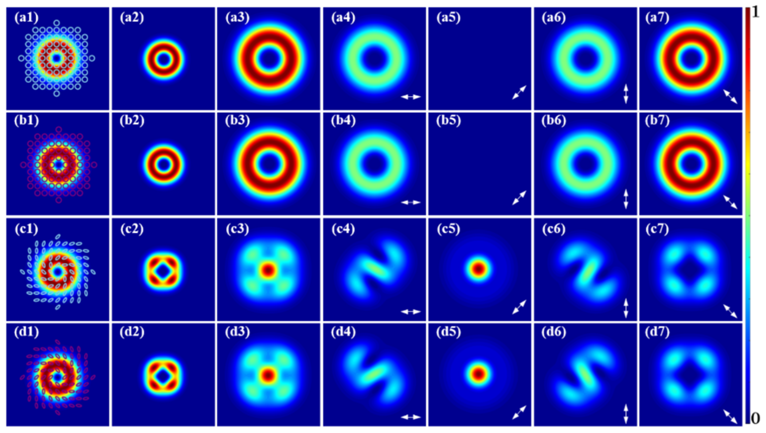
Then, the FFTSs of the SH from circularly polarized VBs at the poles of the HOPS were calculated numerically, and the circularly polarized VBs were used as FF beams, as shown in Figure 2(a1,b1). The SH in-source plane after the nonlinear process is shown in Figure 2(a2,b2). Interestingly, the FFTSs of the SH are relatively simple compared to those of the SH from CVBs, as depicted in Figure 2(a3,b3). From Figure 2(a4–a7,b4–b7), it can be seen that the FFTSs of the SH from circularly polarized VBs remain as 135° linearly polarized VBs similar to the SH in-source plane.
In addition, the FFTSs of the SH from EPCVBs elsewhere excluding the poles and the equator on the HOPS were calculated numerically, and the EPCVBs were used as FF beams, as displayed in Figure 2(c1,d1). After the nonlinear process, the SH in-source plane was shown in Figure 2(c2,d2). FFTSs of the SH, as depicted in Figure 2(c3,d3), are noteworthy. The horizontal and vertical FFTSs of the SH follow S-shaped profiles, with the opening direction related to the chirality of the FF beams, as illustrated in Figure 2(c4,d4,c6,d6). The chirality originates from the intramode phase of the EPCVBs. During the propagation of the SH of EPCVBs, the Gouy phase accumulates, leading to the additional intramode phase [26]. The FFTSs at 45° are similar to the Gaussian beams, as illustrated in Figure 2(c5,d5). In the 135° direction, as shown in Figure 2(c7,d7), the FFTSs consist of four connected bright spots, which differ from Figure 1(a7–d7). It can be attributed to the changes in bases on the HOPS during the nonlinear process. The two orthogonal bases of the HOPS beams can be expressed as R: exp(ipφ); L: exp(−ipφ) [13,14], while the nonlinear interactions cause the circular polarization bases to transform into R: exp(2ipφ) + exp(−2ipφ) + 2i; L: exp(2ipφ) + exp(−2ipφ) − 2i [26]. The two bases are more complex and have never been encountered before, which has led to interesting FFTSs of the SH.
More importantly, the FFTSs of the SH from the HOPS beams with p = 2 and 3 could be utilized for the manipulation of transverse mode-locking states [39], and high-dimensional polarization entangled state [40]. In addition, the FFTSs may be applied to the coherent control process [41]. Therefore, the corresponding FFTSs were also calculated numerically, as shown in Figures S1–S4 of the Supporting Materials. As can be seen in Figures S2(a3–d3) and S4(a3–d3), the FFTSs of the SH from the HOPS beams with p = 2 and 3 are more diverse and intriguing.

3. Results and Discussions

The experimental setup was established to verify the simulated results. As shown in Figure 3, a 1064 nm linearly polarized solid-state laser (HUARAY, PINE-1064-20, Wuhan, China) was applied as the pump source, with the maximum output average power of 20 W, a repetition frequency of 1 kHz~1 MHz, and typical pulse width of 10 ps. The laser output power was set to 250 mW, with a repetition frequency of 100 kHz during the experiment. To maintain the same pulse width and repetition frequency, the half-wave plate (HWP1) and polarizing beam splitter (PBS) were utilized to adjust the incident power. Then, by rotating the fast axes of the quarter-wave plate (QWP) and the second half-wave plate (HWP2), the arbitrary polarized beams satisfying the polarization ellipse can be obtained, which can be converted into the HOPS beams [42] by applying the Q-plate, a polarization device composed of the twisted nematic liquid crystal. The HOPS beams can be obtained by using the Q-plate (LBTEK, VR1-1064, Changsha, China). In the experiment, the order p of the Q-plate used by us is 1, 2, and 3, respectively.
Next, the 4f system, which consisted of two lenses (f1 = 100 mm, f2 = 25.4 mm), was used to image and focus the pump beams to the center position of the two orthogonally placed 5% MgO: PPLN crystals, of which the size is 2.1 × 1 × 1 mm3, and the poling period is 6.97 µm [14]. The radius of the HOPS was controlled to approximately 150 µm at the center of two MgO: PPLN crystals. To balance the conversion efficiency of each component, the total length of the two crystals should not exceed the Rayleigh length of the HOPS beams [43]. In addition, a lens (f3 = 50 mm) was used to collimate and image the SH beams, and the 45° dichroic mirror (DM) was employed to filter out the HOPS beams. During the experiment, the beam profiles of the SH were collected with the beam quality analyzer (THORLABS, BC106N-VIS/M, Newton, MA, USA) placed in different propagation regions.
In the first set of experiments, the FFTSs of the SH from CVBs were conducted, and the CVBs at the equator of the HOPS were used as FF beams in Figure 4(a1–d1). The SH in-source plane with a central dark core is presented in Figure 4(a2–d2). However, the central dark core disappears in the far field, as shown in Figure 4(a3–d3). The dramatic evolution of the SH from the source plane to far field can be attributed to the azimuthal position compression in OAM space and the broadening of the OAM spectrum [44]. In order to explore the FFTSs of the SH, a polarizer (LBTEK, AFPL25-VIS, Changsha, China) was placed in front of the beam quality analyzer, and the 0°, 45°, 90° and 135° linear polarization components were obtained by rotating the polarizer, as illustrated in Figure 4(a4–a7,b4–b7,c4–c7,d4–d7). Even more interesting is that the horizontal and vertical FFTSs of the SH transform into three petals, which are similar to the Hermitian–Gaussian modes, as presented in Figure 4(a4–d4,a6–d6). In the 45° direction, the hollow beams evolve into Gaussian-like beams, as displayed in Figure 4(a5–d5), containing a faintly illuminated ring at the periphery. However, in the 135° direction, the FFTSs of the SH, as shown in Figure 4(a7–d7), are similar to those in the source plane [14].
In addition, the FFTSs of the SH from circularly polarized VBs were conducted. The FF circularly polarized VBs at the poles of the HOPS are shown in Figure 5(a1,b1), of which the SH in-source plane is presented in Figure 5(a2,b2). Meanwhile, the FFTSs of the SH, as shown in Figure 5(a3,b3), from the circularly polarized VBs are transformed into 135° linearly polarized VBs, as verified in Figure 5(a4–a7,b4–b7), because, in the nonlinear process, the phase difference between the horizontal and vertical components changes from π/2 to π. Specifically, the Jones matrix of the right-circularly polarized vortex beam can be written as follows: E F F R v o r t e x = ( cos p φ + i sin p φ ) ( sin p φ i cos p φ ) T . After the two components of the FF are modulated by the nonlinear interaction, the Jones matrix of the SH from the HOPS beams is given by: E S H v o r t e x = ( cos p φ + i sin p φ ) 2 ( sin p φ i cos p φ ) 2 T = exp ( 2 i p φ ) 1 1 T [14]. Compared to the FF beams, although the polarization state of the SH in-source plane changes, it remains an eigen-mode of free space and its topological structure does not change during propagation [38]. The experimental results agree well with the simulation results, as illustrated in Figure 1 and Figure 2.
In addition, the FFTSs of the SH from EPCVBs were demonstrated, and the FF EPCVBs are illustrated in Figure 5(c1,d1), of which the SH in-source plane is given in Figure 5(c2,d2), while the FFTSs of the SH from EPCVBs are displayed in Figure 5(c3,d3). Specifically, the horizontal and vertical FFTSs of the SH from EPCVBs follow S-shaped patterns, as presented in Figure 5(c4,d4,c6,d6), and the rotation direction is related to that of the EPCVBs. The 45° and 135° components are also similar to those from CVBs, as shown in Figure 5(c5,d5,c7,d7). The FFTSs of the SH result from intensity and phase modulation in the nonlinear interaction process, which breaks the symmetry of the HOPS beams, leading to the coupling of spin and orbital angular momentum [31]. To sum up, the FFTSs of the SH may be derived from the topological phase transition, which leads to a significant transition from the standard HOPS to more complex polarized Poincaré sphere [45], closely related to non-reciprocal wave dynamics [25].
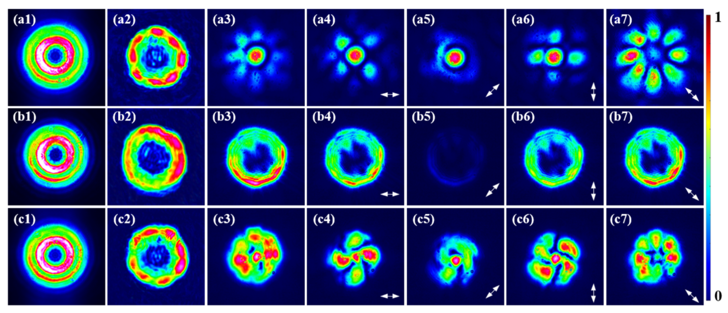
Then, experiments were conducted with HOPS beams with p = 2 as the FF beams, as depicted in Figure 6(a1–c1), of which the SH is shown in Figure 6(a2–c2), while the corresponding FFTSs of the SH from radially polarized beams, left-handed 90° EPCVBs, and the left-circularly polarized VBs are illustrated in Figure 6(a3–c3), respectively. For the SH in the far field from CVBs and EPCVBs with p = 2, the FFTSs are more complex, with the central intensity peaking, while the outer regions are surrounded by bright spots, as shown in Figure 6(a3,c3). Notably, the number of outer bright spots of the SH in the far field is eight, consistent with those observed at the source plane. Nevertheless, the horizontal and vertical components exhibit only half the number of outer bright spots in the far field, as shown in Figure 6(a4,a6,c4,c4). These phenomena are related to the doubling of the p in the nonlinear process. For the circularly polarized VBs, the FFTSs of the SH remain largely unchanged compared to those in the source plane, as shown in Figure 6(b2,b3).
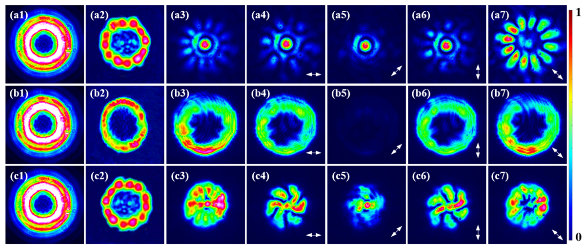
Finally, the FFTSs of the SH from HOPS beams with p = 3 are illustrated in Figure 7. The FF beams, including radially polarized beams, left-circularly polarized VBs, and left-handed 90° EPCVBs are shown in Figure 7(a1–c1), of which the SH in-source plane is given in Figure 7(a2–c2), while the FFTSs of the corresponding SH are displayed in Figure 7(a3–c3). In the case of CVBs and EPCVBs, the FFTSs exhibit lobe-like structures in which the central dark core vanishes, giving rise to the maximum intensity at the beam center, encircled by 12 bright spots, as presented in Figure 7(a3,c3). It is particularly worth noting that the horizontal and vertical FFTSs of the SH from EPCVBs also exhibit lobe structures, and the rotation direction is determined by the chirality of the FF beams, as shown in Figure 7(c4,c6). Furthermore, the SHs in the far field from circularly polarized VBs are linearly polarized beams, as displayed in Figure 7(b4–b7).
Overall, for the CVBs and EPCVBs, the number of outer bright spots of the SH in the far field is related to the p. As the p increases from 1 to 3, the number of bright spots increases from 4 to 12. In addition, for the CVBs and EPCVBs with p = 2 and 3, the evolution mechanism of the topological structures under 45° and 135° polarization is similar to that observed in HOPS beams with p = 1. However, for EPCVBs with p = 2 and 3, the FFTSs of the SH exhibit imperfections along the 45° direction, as shown in Figure 6(c5) and Figure 7(c5). The slight deviation in the relative positions of the two nonlinear crystals, imperfect collimation of the optical path, and poor beam quality can all lead to deviations between the experimental and theoretical results. For the circularly polarized VBs, the central dark core of the SH in the far field expands with increasing p. In addition, for the circularly polarized VBs with p = 2 and 3 as the FF beams, the experimental results are similar to the SH in the far field from circularly polarized VBs with p = 1, which is crucial for achieving the conformal transformation of the HOPS beams [46,47].

4. Conclusions

In summary, the FFTSs of the SH from HOPS, including circularly polarized VBs, CVBs and EPCVBs, were demonstrated and reported. The results indicated that for the circularly polarized VBs, the FFTSs of the SH still exhibit the 135° linearly polarized VBs, which is similar to that of the SH in-source plane, because the SH is the eigen-mode of free space [14], while for the CVBs and EPCVBs, the topological structures cannot remain stable during transmission due to the topological phase transition [26]. Especially of note, for the EPCVBs, the FFTSs of SH display the maximum light intensity at the center, but the FFTSs in the horizontal and vertical directions reveal rotational symmetry related to the chirality of EPCVBs. Moreover, the results reveal the evolution mechanisms of the SH from the HOPS in the far field, which may facilitate the application of the SH from HOPS beams.

Supplementary Materials

The following supporting information can be downloaded at: https://www.mdpi.com/article/10.3390/photonics12050407/s1, Figure S1: The numerical results on the SH in-source plane from HOPS beams with p = 2; Figure S2: The numerical results on the SH in the far-field from HOPS beams with p = 2; Figure S3: The numerical results on the SH in-source plane from HOPS beams with p = 3; Figure S4: The numerical results on the SH in far-field from HOPS beams with p = 3.

Author Contributions

Conceptualization, Y.L. and Y.H.; Formal Analysis, Y.L. and Z.Z.; Funding Acquisition, Y.H.; Methodology, Y.L.; Software, Y.L. and L.F.; Supervision, Y.W. and Y.H.; Validation, J.D. and B.L.; Writing—Original Draft, Y.L.; Writing—Review and Editing, Y.H. All authors have read and agreed to the published version of the manuscript.

Funding

This work was supported by the Jiangsu Provincial Key Research and Development Program (BE2022143), and the National Natural Science Foundation of China (62205133).

Institutional Review Board Statement

Not applicable.

Informed Consent Statement

Not applicable.

Data Availability Statement

The data presented in this study are available on request from the corresponding author.

Conflicts of Interest

Author Bo Li was employed by the company Optics Valley Laboratory. The remaining authors declare that the research was conducted in the absence of any commercial or financial relationships that could be construed as a potential conflict of interest.

References

  1. Milione, G.; Sztul, H.I.; Nolan, D.A.; Alfano, R.R. Higher-Order Poincaré Sphere, Stokes Parameters, and the Angular Momentum of Light. Phys. Rev. Lett. 2011, 107, 053601. [Google Scholar] [CrossRef] [PubMed]
  2. Chen, S.Z.; Zhou, X.X.; Liu, Y.C.; Wen, S.C. Generation of arbitrary cylindrical vector beams on the higher order Poincaré sphere. Opt. Lett. 2014, 39, 5274–5276. [Google Scholar] [CrossRef]
  3. Zhang, S.Y.; Zhao, W.Q.; Dou, J.T.; Hu, Y.Y. Full higher-order Poincaré sphere beam mode-locked fiber laser. Opt. Laser Technol. 2024, 176, 110933. [Google Scholar] [CrossRef]
  4. Forbes, A.; Oliveira, M.D.; Dennis, M.R. Structured light. Nat. Photonics 2021, 15, 253–262. [Google Scholar] [CrossRef]
  5. Rui, G.H.; Zhan, Q.W. Trapping of resonant metallic nanoparticles with engineered vectorial optical field. Nanophotonics 2014, 3, 351–361. [Google Scholar] [CrossRef]
  6. Wang, Q.; Tu, C.H.; He, H.; Xia, Z.C.; Hou, X.Z.; Li, Y.N.; Wang, H.T. Local angular momentum induced dual orbital effect. APL Photonics 2022, 7, 086102. [Google Scholar] [CrossRef]
  7. Carruthers, A.E.; Walker, J.S.; Casey, A.; Orr-Ewing, A.J.; Reid, J.P. Selection and characterization of aerosol particle size using a Bessel beam optical trap for single particle analysis. Phys. Chem. Chem. Phys. 2012, 14, 6741–6748. [Google Scholar] [CrossRef]
  8. Drevinskas, R.; Zhang, J.Y.; Beresna, M.; Gecevičius, M.; Kazanskii, A.G.; Svirko, Y.P.; Kazansky, P.G. Laser material processing with tightly focused cylindrical vector beams. Appl. Phys. Lett. 2016, 108, 221107. [Google Scholar] [CrossRef]
  9. Liu, M.; Lei, Y.; Yu, L.; Fang, X.; Ma, Y.; Liu, L.; Zheng, J.; Gao, P. Super-resolution optical microscopy using cylindrical vector beams. Nanophotonics 2022, 11, 3395–3420. [Google Scholar] [CrossRef]
  10. Xiao, F.J.; Shang, W.Y.; Zhu, W.R.; Han, L.; Premaratne, M.; Mei, T.; Zhao, J.L. Cylindrical vector beam-excited frequency-tunable second harmonic generation in a plasmonic octamer. Photonics Res. 2018, 6, 157–161. [Google Scholar] [CrossRef]
  11. Zhang, L.; Lin, F.; Qiu, X.D.; Chen, L.X. Full vectorial feature of second-harmonic generation with full Poincaré beams. Chin. Opt. Lett. 2019, 17, 091901. [Google Scholar] [CrossRef]
  12. Saripalli, R.K.; Ghosh, A.; Chaitanya, N.A.; Samanta, G.K. Frequency-conversion of vector vortex beams with space-variant polarization in single-pass geometry. Appl. Phys. Lett. 2019, 115, 051101. [Google Scholar] [CrossRef]
  13. Buono, W.T.; Forbes, A. Nonlinear optics with structured light. Opto-Electron. Adv. 2022, 5, 210174. [Google Scholar] [CrossRef]
  14. Jiang, Q.N.; Zhao, M.L.; Wang, Y.X.; Wang, S.L.; Dou, J.T.; Liu, J.; Li, B.; Hu, Y.Y. Second harmonic of higher-order Poincaré sphere beam with two orthogonal 5% MgO: PPLN crystals. APL Photonics 2024, 9, 056111. [Google Scholar] [CrossRef]
  15. Liu, H.G.; Li, H.; Zheng, Y.L.; Chen, X.F. Nonlinear frequency conversion and manipulation of vector beams. Opt. Lett. 2018, 43, 5981–5984. [Google Scholar] [CrossRef]
  16. Chaitanya, N.A.; Jabir, M.V.; Samanta, G.K. Efficient nonlinear generation of high power, higher order, ultrafast “perfect” vortices in green. Opt. Lett. 2016, 41, 1348–1351. [Google Scholar] [CrossRef] [PubMed]
  17. Tang, Y.T.; Li, K.F.; Zhang, X.C.; Deng, J.H.; Li, G.X.; Brasselet, E. Harmonic spin–orbit angular momentum cascade in nonlinear optical crystals. Nat. Photonics 2020, 14, 658–662. [Google Scholar] [CrossRef]
  18. Fickler, R.; Lapkiewicz, R.; Ramelow, S.; Zeilinger, A. Quantum entanglement of complex photon polarization patterns in vector beams. Phys. Rev. A 2014, 89, 060301. [Google Scholar] [CrossRef]
  19. Bliokh, K.Y.; Fortuño, F.J.R.; Nori, F.; Zayats, A.V. Spin–orbit interactions of light. Nat. Photonics 2015, 9, 796–808. [Google Scholar] [CrossRef]
  20. Cardano, F.; Marrucci, L. Spin-orbit photonics. Nat. Photonics 2015, 9, 776–778. [Google Scholar] [CrossRef]
  21. Fatemi, F.K. Cylindrical vector beams for rapid polarization-dependent measurements in atomic systems. Opt. Express 2011, 19, 25143–25150. [Google Scholar] [CrossRef] [PubMed]
  22. He, C.; Shen, Y.J.; Forbes, A. Towards higher-dimensional structured light. Light Sci. Appl. 2022, 11, 205. [Google Scholar] [CrossRef] [PubMed]
  23. Pereira, L.J.; Buono, W.T.; Tasca, D.S.; Dechoum, K.; Khoury, A.Z. Orbital-angular-momentum mixing in type-II second-harmonic generation. Phys. Rev. A 2017, 96, 053856. [Google Scholar] [CrossRef]
  24. Rao, A.S.; Miamoto, K.; Omatsu, T. Ultraviolet intracavity frequency-doubled Pr3+:LiYF4 orbital Poincaré laser. Opt. Express 2020, 28, 37397–37405. [Google Scholar] [CrossRef]
  25. Wu, H.J.; Yang, H.R.; Rosales-Guzmán, C.; Gao, W.; Shi, B.S.; Zhu, Z.H. Vectorial nonlinear optics: Type-II second-harmonic generation driven by spin-orbit-coupled fields. Phys. Rev. A 2019, 100, 053840. [Google Scholar] [CrossRef]
  26. Wu, H.J.; Zhou, Z.Y.; Gao, W.; Shi, B.S.; Zhu, Z.H. Dynamic tomography of the spin-orbit coupling in nonlinear optics. Phys. Rev. A 2019, 99, 023830. [Google Scholar] [CrossRef]
  27. Zhou, Z.Y.; Zhu, Z.H.; Liu, S.L.; Li, Y.H.; Shi, S.; Ding, D.S.; Chen, L.X.; Gao, W.; Guo, G.C.; Shi, B.S. Quantum twisted double-slits experiments: Confirming wavefunctions’ physical reality. Sci. Bull. 2017, 62, 1185–1192. [Google Scholar] [CrossRef]
  28. Zhen, W.; Ren, Z.C.; Wang, X.L.; Ding, J.; Wang, H.T. Polarization structure transition of C-point singularities upon reflection. Sci. China Phys. Mech. 2025, 68, 244211. [Google Scholar] [CrossRef]
  29. Neugebauer, M.; Banzer, P.; Bauer, T.; Orlov, S.; Lindlein, N.; Aiello, A.; Leuchs, G. Geometric spin Hall effect of light in tightly focused polarization-tailored light beams. Phys. Rev. A 2014, 89, 013840. [Google Scholar] [CrossRef]
  30. Hu, Y.Y.; Ma, Z.Y.; Zhao, W.Q.; Zhao, J.; Liu, J.; Jing, Q.L.; Dou, J.T.; Li, B. Controlled generation of mode-switchable nanosecond pulsed vector vortex beams from a Q-switched fiber laser. Opt. Express 2022, 30, 33195–33207. [Google Scholar] [CrossRef]
  31. Ling, X.H.; Guan, F.X.; Cai, X.D.; Ma, S.J.; Xu, H.X.; He, Q.; Xiao, S.Y.; Zhou, L. Topology-Induced Phase Transitions in Spin-Orbit Photonics. Laser Photonics Rev. 2021, 15, 2000492. [Google Scholar] [CrossRef]
  32. Ma, Z.Y.; Zhao, W.Q.; Zhao, J.; Liu, J.; Jing, Q.L.; Dou, J.T.; Li, B.; Hu, Y.Y. Generation of arbitrary higher-order Poincaré sphere beam from a ring fiber laser with cascaded Q-plates. Opt. Laser Technol. 2022, 156, 108552. [Google Scholar] [CrossRef]
  33. Duque, C.B.; Sucerquia, J.G. Non-approximated Rayleigh–Sommerfeld diffraction integral: Advantages and disadvantages in the propagation of complex wave fields. Appl. Opt. 2019, 58, G11–G18. [Google Scholar] [CrossRef]
  34. Collins, S.A. Lens-System Diffraction Integral Written in Terms of Matrix Optics. J. Opt. Soc. Am. 1970, 60, 1168–1177. [Google Scholar] [CrossRef]
  35. Cai, Y.J.; He, S.L. Propagation of hollow Gaussian beams through apertured paraxial optical systems. J. Opt. Soc. Am. A 2006, 23, 1410–1418. [Google Scholar] [CrossRef]
  36. Zhang, L.; Qiu, X.D.; Li, F.S.; Liu, H.G.; Chen, X.F.; Chen, L.X. Second harmonic generation with full Poincaré beams. Opt. Express 2018, 26, 11678–11684. [Google Scholar] [CrossRef]
  37. Wen, Z.X.; Wang, Y.X.; Dou, J.T.; Fan, L.; Li, B.; Hu, Y.Y. Controlled generation of double-ring-shaped generalized cylindrical vector beams from a YVO4/Nd: YVO4 laser with ring-shaped defect mirror. Opt. Laser Technol. 2025, 186, 112718. [Google Scholar] [CrossRef]
  38. Zhan, Q.W. Cylindrical vector beams: From mathematical concepts to applications. Adv. Opt. Photon. 2009, 1, 1–57. [Google Scholar] [CrossRef]
  39. Zhang, Z.L.; Gao, Y.; Li, X.J.; Wang, X.; Zhao, S.Y.; Liu, Q.; Zhao, C.M. Second harmonic generation of laser beams in transverse mode locking states. Adv. Photonics 2022, 4, 026002. [Google Scholar] [CrossRef]
  40. Liu, S.L.; Zhou, Z.Y.; Liu, S.K.; Li, Y.H.; Li, Y.; Yang, C.; Xu, Z.H.; Liu, Z.D.; Guo, G.C.; Shi, B.S. Coherent manipulation of a three-dimensional maximally entangled state. Phys. Rev. A 2018, 98, 062316. [Google Scholar] [CrossRef]
  41. Forbes, A. Sculpting electric currents with structured light. Nat. Photonics 2020, 14, 656–657. [Google Scholar] [CrossRef]
  42. Cao, L.Y.; Zhang, M.M.; Dou, J.T.; Zhao, J.; Hu, Y.Y.; Li, B. Controlled generation of order-switchable cylindrical vector beams from a Nd: YAG laser. Chin. Opt. Lett. 2023, 21, 101401. [Google Scholar] [CrossRef]
  43. da Silva, N.R.; de Oliveira, A.G.; Arruda, M.F.Z.; de Araújo, R.M.; Soares, W.; Walborn, S.; Gomes, R.; Ribeiro, P.S. Stimulated Parametric Down-Conversion with Vector Vortex Beams. Phys. Rev. Appl. 2021, 15, 024039. [Google Scholar] [CrossRef]
  44. Arnold, S.F.; Barnett, S.M.; Yao, E.; Leach, J.; Courtial, J.; Padgett, M. Uncertainty principle for angular position and angular momentum. New J. Phys. 2004, 6, 103. [Google Scholar] [CrossRef]
  45. Sun, X.; Liu, L.; Zhu, Q.; Huang, W.; Zhang, Y.; Wang, W.; Chen, Y.; Geng, Y. Unitary transformation in polarization of vector beams via biaxial cascade crystals. J. Opt. 2020, 22, 025602. [Google Scholar] [CrossRef]
  46. Wang, W.; Zhou, L.J.; Dou, J.T.; Li, B.; Hu, Y.Y. Controlled generation of OAM-switchable vortex beams at 639 nm from a Pr3+: YLF laser. Opt. Commun. 2024, 563, 130576. [Google Scholar] [CrossRef]
  47. Wu, H.J.; Yu, B.S.; Zhu, Z.H.; Gao, W.; Ding, D.S.; Zhou, Z.Y.; Hu, X.P.; Rosales-Guzmán, C.; Shen, Y.; Shi, B.S. Conformal frequency conversion for arbitrary vectorial structured light. Optica 2022, 9, 187–196. [Google Scholar] [CrossRef]
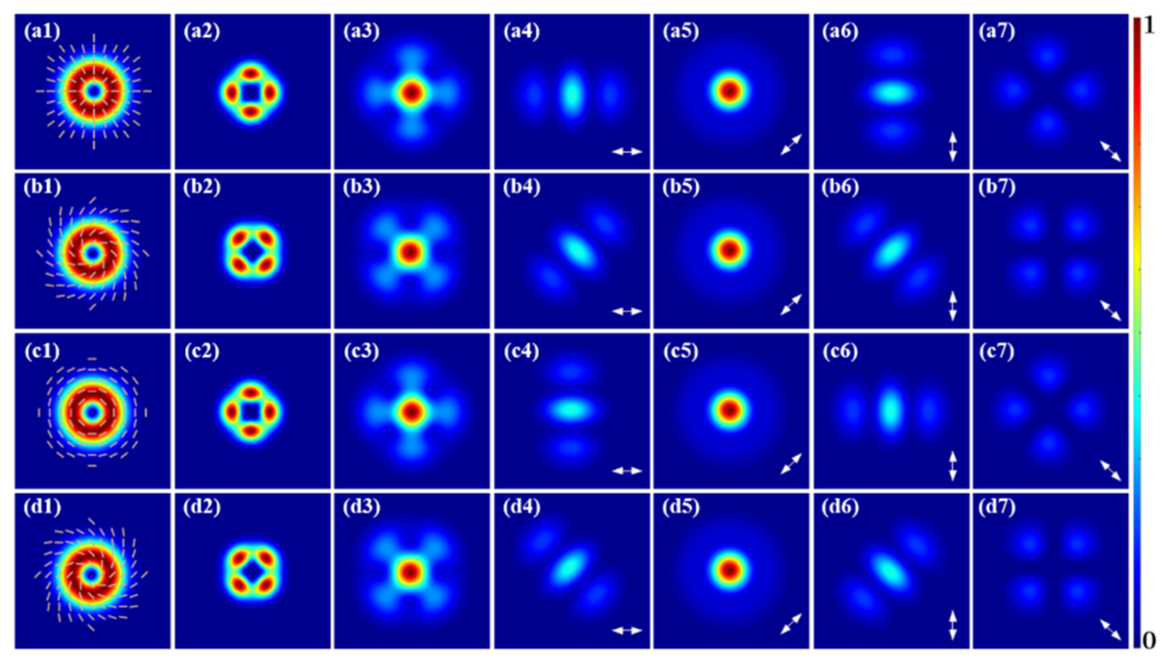
Figure 1. The numerical results on the far-field SH from CVBs with p = 1. (a1d1) The FF beams, including the radially polarized beams, 45° CVBs, azimuthally polarized beams, 135° CVBs; (a2d2) the SH in-source plane; (a3d3) the SH in far field; (a4a7,b4b7,c4c7,d4d7) the 0°, 45°, 90° and 135° linear polarization components of the SH in the far field.
Photonics 12 00407 g001
Figure 2. The numerical results on the far-field SH from EPCVBs and circularly polarized VBs with p = 1. (a1d1) The FF beams, including the left-circularly polarized VBs, right-circularly polarized VBs, left-handed 45° EPCVBs, right-handed 135° EPCVBs; (a2d2) the SH in-source plane; (a3d3) the SH in the far field; (a4a7,b4b7,c4c7,d4d7) the 0°, 45°, 90° and 135° linear polarization components of the SH in the far field.
Photonics 12 00407 g002
Figure 3. The experimental setup. HWP1–2: half-wave plate; PBS: polarization beam splitter; QWP: quarter-wave plate; Q-Plate: the polarization device for generating HOPS beams; L1–3: lenses; DM: dichroic mirror; BQP: beam quality analyzers.
Photonics 12 00407 g003
Figure 4. The experimental results on the far-field SH from CVBs with p = 1. (a1d1) The FF beams, including the radially polarized beams, 45° CVBs, azimuthally polarized beams, 135° CVBs; (a2d2) the SH in-source plane; (a3d3) the SH in the far field; (a4a7,b4b7,c4c7,d4d7) the 0°, 45°, 90° and 135° linear polarization components of the SH in the far field.
Photonics 12 00407 g004
Figure 5. The experimental results on the far-field SH from EPCVBs and circularly polarized VBs with p = 1. (a1d1) The FF beams, including the left-circularly polarized VBs, right-circularly polarized VBs, left-handed 45° EPCVBs, and right-handed 135° EPCVBs; (a2d2) the SH in-source plane; (a3d3) the SH in the far field; (a4a7,b4b7,c4c7,d4d7) the 0°, 45°, 90° and 135° linear polarization components of the SH in the far field.
Photonics 12 00407 g005
Figure 6. The experimental results on the far field SH from HOPS beams with p = 2. (a1c1) The FF beams, including radially polarized beams, left-circularly polarized VBs, and left-handed 90° EPCVBs; (a2c2) the SH in-source plane; (a3c3) the SH in the far field; (a4a7,b4b7,c4c7) the 0°, 45°, 90° and 135° linear polarization components of the far-field SH.
Photonics 12 00407 g006
Figure 7. The experimental results on the far field SH from HOPS beams with p = 3. (a1c1) The FF beams, including the 45° CVBs, left-circularly polarized VBs, and right-handed 135° EPCVBs; (a2c2) the SH in-source plane; (a3c3) the SH in the far field; (a4a7,b4b7,c4c7) the 0°, 45°, 90° and 135° linear polarization components of the far-field SH.
Photonics 12 00407 g007
Disclaimer/Publisher’s Note: The statements, opinions and data contained in all publications are solely those of the individual author(s) and contributor(s) and not of MDPI and/or the editor(s). MDPI and/or the editor(s) disclaim responsibility for any injury to people or property resulting from any ideas, methods, instructions or products referred to in the content.