Abstract
We studied paraxial light beams, obtained by a continuous superposition of off-axis Gaussian beams with their phases chosen so that the whole superposition is invariant to free-space propagation, i.e., does not change its transverse intensity shape. Solving a system of five nonlinear equations for such superpositions, we obtained an analytical expression for a propagation-invariant off-axis elliptic Gaussian beam. For such an elliptic beam, an analytical expression was derived for the orbital angular momentum, which was shown to consist of two terms. The first one is intrinsic and describes the momentum with respect to the beam center and is shown to grow with the beam ellipticity. The second term depends parabolically on the distance between the beam center and the optical axis (similar to the Steiner theorem in mechanics). It is shown that the ellipse orientation in the transverse plane does not affect the normalized orbital angular momentum. Such elliptic beams can be used in wireless optical communications, since their superpositions do not interfere in space, if they do not interfere in the initial plane.
1. Introduction
Among the different kinds of light fields, of special interest are form-invariant (or, propagation-invariant) fields. The transverse intensity shape of such beams remains unchanged on free-space propagation (up to scale and rotation). Nonparaxial examples of such fields are plane waves, diffraction-free Bessel beams [1], Mathieu beams [2], and parabolic beams [3]. Well-known paraxial examples are the Hermite−Gaussian and Laguerre−Gaussian beams [4], Gaussian beams with arbitrary located optical vortices [5], and some superpositions of such beams [6,7]. In [8], a general procedure is described for calculating the paraxial propagation-invariant beams, whose transverse intensity distribution has the shape of an arbitrary curve. The procedure is based on using an elementary spiral beam (off-axis Gaussian beam with a wavefront tilt) as a building block. In [9], other building blocks, highly localized wavepackets, were suggested to construct nondiffracting pulsed beams.
In some tasks, however, using light beams with an elliptic intensity cross-section can be advantageous. For example, as shown in [10], adopting elliptic vortex beams for optical data transmission in a turbulent atmosphere reduces the scintillation index [11]. In [12], elliptic vortex beams with a fractional topological charge (number of 2π phase jumps along a contour encompassing either a single optical vortex, i.e., local topological charge, or the whole beam [13]) are used in free-space information transfer to increase the throughput and security. In [14], partially coherent four-petal elliptic Gaussian beams are investigated, also in turbulent atmosphere. It is shown that the number of petals can change on propagation. In optical trapping, elongated intensity distribution is convenient for preventing a particle from moving along one coordinate [15]. In [16,17,18], elliptic Gaussian beams are used to increase the recording throughput of thermochemical laser-induced periodic surface structures.
The interest in the elliptic beams motivates their analytical studies. Generally, the paraxial propagation of a light beam is described by the integral Fresnel transform [19], whose kernel is a quadratic exponential. Thus, analytical description of a Gaussian beam with an arbitrary ellipticity, tilt angle, center position, parabolic wavefront curvature is possible, in principle. Such a description is given in [20]. However, such beams are not propagation invariant and their transverse cross section changes on space propagation. In our paper [21], propagation-invariant elliptic Gaussian beams were considered with an optical vortex in the center, and their orbital angular momentum was derived. On propagation in space, such beams rotate around their center.
In this work, based on the theory of paraxial structurally stable light beams developed in [8], we studied paraxial propagation-invariant elliptic Gaussian beams, similar to [21], but with an arbitrary position of the ellipse center in the transverse plane and with an arbitrary ellipse tilt. For this purpose, as in [8,9], we also use simple beams as building blocks and construct a continuous superposition of elementary spiral light beams [8] on a plane. Then, solving a nonlinear system of five equations to determine the weight coefficients of this superposition, we obtained an analytical expression for the complex amplitude distribution. In addition, we obtained a formula for the orbital angular momentum of such beams. Similar to the Steiner theorem in mechanics, it consists of two terms. The first one coincides with Equation (4) from [22] and describes the intrinsic OAM with respect to the beam center. This term grows with the beam ellipticity. The second term depends parabolically on the distance between the beam’s “center of mass” and the optical axis. It turns out that the ellipse orientation in the transverse plane (tilt angle of the ellipse’s axes to the Cartesian coordinate axes) does not affect the normalized orbital angular momentum.
2. Propagation-Invariant Off-Axis Gaussian Beams
As has been shown in [8] (Formula (6.1)), any function of the following form
where (x, y, z) are the Cartesian coordinates, w0 is the Gaussian beam waist radius, q = 1 + iz/z0, is the Rayleigh range, k = 2π/λ is the wavenumber of light with the wavelength λ, f(x ± iy) is an arbitrary entire analytical function, is a solution of the paraxial wave equation:
and describes a propagation-invariant light field (travelling along the optical axis z), i.e., a field with its transverse intensity shape conserving on free-space propagation, changing only in scale and rotating. Off course, it is meant that the waist radius is much greater than the wavelength, i.e., w0 >> λ, so that the paraxial approximation is valid.
The freedom in choosing the functions f(.) allows the describing of optical fields with very different physical properties. For example, if we choose the cosine function:
with being a complex-valued parameter, then we obtain a cosine vortex beam [23] with its intensity distribution consisting of two light spots (Figure 1a,c) and with an infinite topological charge, since the beam contains an infinite number of optical vortices (Figure 1b,d).
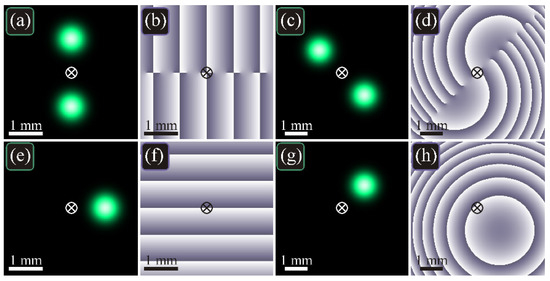
Figure 1.
Intensity (a,c,e,g) and phase (b,d,f,h) distributions of the vortex cosine beam (3) and of the elementary spiral beam (4) in the initial plane (a,b,e,f) and at the Rayleigh distance (c,d,g,h) for the following parameters: wavelength λ = 532 nm, Gaussian beam waist radius w0 = 0.5 mm, scaling factor α0 = w0/4, computation domain |x|, |y| ≤ R with R = 2 mm (in the initial plane) and R = 3 mm (at the Rayleigh distance). The cross in the center shows the optical axis, around which the diffraction pattern rotates on propagation (at the Rayleigh distance, the rotation angle is π/4).
If, instead of the cosine, we choose the exponential, i.e., if we consider a light beam
then, it is expectable that the beam should contain one light spot, rather than two. Such a beam is described in [8] and is called an elementary spiral beam. In contrast to the cosine vortex beam from Figure 1a–d, the intensity distribution of the beam (4) contains a single off-axis spot (Figure 1e,g) and the topological charge of such a beam is zero, since the beam does not contain optical vortices (Figure 1f,h). Thus, despite the cosine is just a sum of two exponentials, using these functions in Equation (1) leads to light beams with drastically different phase distributions.
If we denote 1/α0 = (2q/w2)(xc − iyc) with xc and yc being real numbers (z-dependent), then, separating in Equation (4) the real and the imaginary parts in the exponentials, and dividing by the constant multiplier exp[(xc2 + yc2)/w2] = exp[|w0/(2α0)|2], we can rewrite Equation (4) as follows
with w(z), R(z), ζ(z) being respectively the beam width, the wavefront curvature radius, and the Gouy phase at the distance z [4]:
As seen from Equation (5), xc and yc are the Cartesian coordinates of the intensity maximum (center of the Gaussian beam) at the distance z, which are related with the Cartesian coordinates of the beam center (xc0, yc0) in the initial plane as follows:
It is also seen from Equation (5) that the light field is an off-axis Gaussian beam and an inclined plane wave is added to the wavefront with the inclination angle matching the shift of the light spot and inclination direction orthogonal to the direction from the optical axis to this spot [Figure 1e,f]. It is this matching that makes the beam propagation invariant, since, on space propagation, the widening of the Gaussian beam is proportional to its moving away from the optical axis. For example, at the Rayleigh distance, z = z0, the beam width grows times, and its distance from the optical axis also grows times, and it is rotated by the angle π/4. Thus, all such beams would together make a pattern that does not change on propagation.
The beam given by Equations (4) and (5) is a basic beam for constructing other propagation-invariant light beams. In [8], a general procedure is described for constructing the propagation-invariant beams with the shape of an arbitrary curve. Below we investigate analytically a superposition of the beams (5), but in the whole transverse plane, rather than along a curve (as in [8]). We show that it leads to the analytical description of an off-axis elliptic Gaussian beam, which is invariant to space propagation and rotating around the optical axis.
3. Propagation-Invariant Elliptic Gaussian Beams
Since our approach is different from that in Ref. [8], we give in this Section all the intermediate expressions.
Using Equation (7), Equation (5) can be rearranged and written via the coordinates of the beam center in the initial plane:
Using the beams from Equation (8) as a basis, we can construct a continuous superposition with the weight coefficients in a Gaussian-like (quadratic-exponential) dependence on the beams’ center positions:
where pxx, pyy, pxy, px, py are some numbers (generally, complex) that define the most contributing constituent beam (8) in the superposition (9) and how fast the contributions decay for other constituent beams.
Rearrangement of the exponentials in Equation (9) yields
The integral of the quadratic-exponential is well known and, therefore,
with G = (1 + pxx)(1 + pyy) − (pxy)2.
In the dimensionless Cartesian coordinates, rotated by an angle equal to the Gouy phase and normalized by the beam width w:
the complex amplitude (11) reads as
or
with
The real parts of these coefficients (15) define the position, sizes, and orientation of the elliptic light spot. On the other hand, if an elliptic Gaussian light spot in the initial plane is located in the point (x0, y0) (spot center), is tilted by the angle α from the x-axis, and has the sizes σx and σy (Figure 2), its complex amplitude is given by
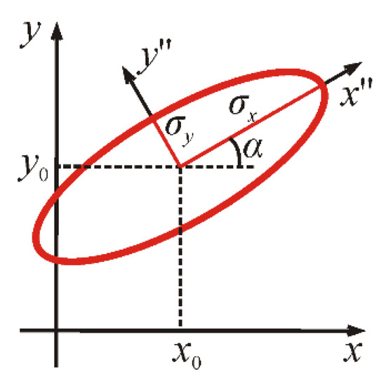
Figure 2.
Geometric parameters of an elliptic light spot.
Thus, for the beam (14) to describe such an elliptic spot, the following conditions should be fulfilled (we suppose that all the superposition coefficients, pxx, pyy, pxy, px, py are real valued):
The system (17) consists of 5 nonlinear equations. However, it turned out that it can be solved analytically. Summing the first two equations, we obtain the following condition:
This condition means that the beams (5) do not allow the construction of an elliptic beam with an arbitrary size. The transverse sizes of the ellipse should be related by Equation (18), according to which, the −2-th power mean [24] of these sizes (i.e., [(σx–2 + σy–2)/2]–1/2) equals the waist radius w0 of the elementary spiral beams (4), (5), used in constructing the superposition. We call this radius w0 an effective waist radius, since the elliptic Gaussian beam propagates in space with the same phase velocity (Gouy phase) as does a circular Gaussian beam with the waist radius w0.
As it turns out, the rest of the parameters of the ellipse (x0, y0, α) can be arbitrary and, for any of their values, the system (17) has a solution. Substituting the derived values pxx, pyy, pxy, px, py into Equation (13), we obtain:
with
Returning from the coordinates (12) to the original coordinates, we obtain the final expression for the complex amplitude:
Equation (22) is the main result if this paper. In the next Section, we show the simulation results based on Equation (22).
4. Numerical Modeling
Figure 3 illustrates the intensity and phase distributions of two elliptic beams (22) in the initial plane and at the Rayleigh distance.
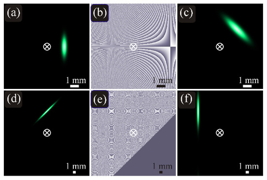
Figure 3.
Intensity (a,c,d,f) and phase (b,e) distributions of the propagation-invariant off-axis elliptic Gaussian beam (22) in the initial plane (a,b,d,e) and at the Rayleigh distance z = z0 (c,f) for the following parameters: wavelength λ = 532 nm, Gaussian beam waist radii σx = 1425 μm and σy = 365 μm (w0 = 500 μm) (a–c) and σx = 4583 μm and σy = 355 μm (w0 = 500 μm) (d–f), coordinates of the beam center (x0, y0) = (2, 0) mm (a–c) and (x0, y0) = (0, 7.5) mm (d–f), tilt angle of the major ellipse axis to the x-axis α = π/2 (a–c) and α = π/4 (d–f), computation domain |x|, |y| ≤ R with R = 5 mm (a–c) and R = 15 mm (d–f). The cross in the center shows the optical axis, around which the diffraction pattern rotates on propagation. Distributions in the initial plane are obtained by Equation (22), whereas at the Rayleigh distance they are computed numerically with the Fresnel transform and, for comparison, also by Equation (22) (the differences are visually undistinguishable). The triangular area of homogeneous phase (e) is the area of ultralow intensity, which is treated by the computation software as the exact zero.
Figure 3 confirms that, after free-space propagation, the intensity distributions change only in scale and are rotated with respect to the origin (optical axis), i.e., the solution (22) of the paraxial wave Equation (2) is stable.
On propagation, both these beams acquire the same Gouy phase as a circular Gaussian beam with the waist radius w0 = 500 μm. Therefore, the superposition of such beams also does not change its shape on propagation.
For instance, such beams can be used to construct a propagation-invariant two-petal superposition. Such fields are used in single-molecule microscopy and for improving the longitudinal resolution in imaging systems [25]. In addition, controllable rotation makes it possible to use these beams for distance measurement. The ellipse orientation (tilt angle φ to the horizontal axis x) depends on the propagation distance along the optical axis z: φ(z) = α + ζ(z), where α is the initial orientation (Figure 2) and ζ(z) is the Gouy phase given by Equation (6). Figure 4 depicts the intensity and phase distributions of the two-petal beam, composed of two opposite elliptic Gaussian beams (22), in the initial plane and at the Rayleigh distance.
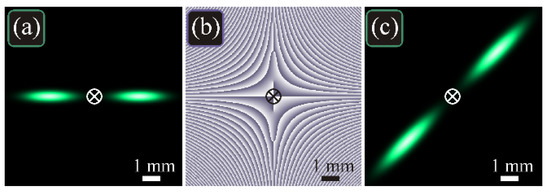
Figure 4.
Distributions of intensity (a,c) and phase (b) of the propagation-invariant two-petal beam in the initial plane (a,b) and at the Rayleigh distance z = z0 (c) for the following parameters: wavelength λ = 532 nm, waist radii of the two opposite elliptic Gaussian beams σx = 1617 μm and σy = 362 μm (i.e., w0 = 500 μm), positions of the beam centers (x0, y0) = (±2.5, 0) mm, tilt angle of the major ellipse axis to the x-axis α = 0, computation domain |x|, |y| ≤ R (R = 5 mm). The cross in the center shows the optical axis, around which the diffraction pattern rotates on propagation.
The same way, we can construct, for instance, triangular or square propagation-invariant beams. Figure 5 depicts the intensity and phase distributions of the triangular beam, composed of three elliptic Gaussian beams (22), in the initial plane, near field (z = z0/2), at the Rayleigh distance (z = z0), and in the far field (z = 5z0). Figure 6 depicts the intensity and phase distributions of the off-axis square beam, composed of four elliptic Gaussian beams (22), in the same planes.
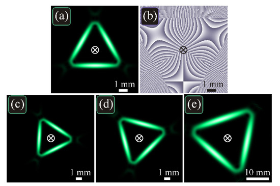
Figure 5.
Intensity (a,c–e) and phase (b) distributions of the triangular propagation-invariant beam in the initial plane (a,b), in the near field z = z0/2 (c), at the Rayleigh distance z = z0 (d), and in the far field z = 5z0 (e) for the following parameters: wavelength λ = 532 nm, waist radii of all three elliptic Gaussian beams σx = 3102 μm and σy = 356 μm (w0 = 500 μm), coordinates of the beam centers (x0p, y0p) = (r0 cos φp, r0 sin φp) (r0 = 1.768 mm, φp = π/6 + 2πp/3, p = 0, 1, 2), tilt angles of the major axes of the ellipses to the x-axis αp = φp + π/2, computation domain |x|, |y| ≤ R with R = 5 mm (a,b), R = 10 mm (c,d), and R = 20 mm (e). The cross in the center shows the optical axis, around which the diffraction pattern rotates on propagation. The initial field (a,b) was obtained by Equation (22) (with a phase shift 2π/3 between the beams to avoid the destructive interference in the corners), whereas distributions in the other planes (c–e) were obtained by the numerical Fresnel transform.
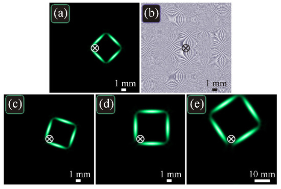
Figure 6.
Intensity (a,c–e) and phase (b) distributions of the off-axis square propagation-invariant beam in the initial plane (a,b), in the near field z = z0/2 (c), at the Rayleigh distance z = z0 (d), and in the far field z = 5z0 (e) for the following parameters: wavelength λ = 532 nm, waist radii of all four elliptic Gaussian beams σx = 2152 μm and σy = 358 μm (w0 = 500 μm), coordinates of the beam centers (x0p, y0p) = (r0 + r0 cos φp, r0 sin φp) (r0 = 2.5 mm, φp = π/4 + πp/2, p = 0, 1, 2, 3), tilt angles of the major axes of the ellipses to the x-axis αp = φp + π/2, computation domain |x|, |y| ≤ R with R = 10 mm (a–d) and R = 30 mm (e). The cross in the center shows the optical axis, around which the diffraction pattern rotates on propagation. The initial field (a,b) was obtained by Equation (22), whereas distributions in the other planes (c-e) were obtained by the numerical Fresnel transform.
5. Beam Power and the Orbital Angular Momentum
For a paraxial light beam, its power and orbital angular momentum are obtained by the following formulae [26]:
Substituting the complex amplitude (22) into these formulae, we obtain expressions for the power and OAM of the off-axis elliptic propagation-invariant Gaussian beam:
Dividing the OAM by power, we obtain the normalized OAM:
Equation (27) shows that shifting the beam from the optical axis leads to a parabolic growth of the normalized OAM with the shift distance r0, which is consistent with the Steiner theorem in mechanics. It is also seen from Equation (27) that the OAM depends on the beam ellipticity, but the tilt of the ellipse to the coordinate axes does not affect the normalized OAM. At r0 = 0, the obtained expression coincides with that given in [21].
Numerical computation confirms the expression (27). For instance, the theoretical normalized OAM value of the beam from Figure 3a–c is 35.328. The numerical computation by Equations (23) and (24) yields the values 35.022 in the initial plane (Figure 3a) and 34.881 at the Rayleigh distance (Figure 3c). For a narrower beam from Figure 3d–f, the theoretical OAM is 491. By numerical computation (but over a wider domain, |x|, |y| ≤ R with R = 30 mm, and with finer sampling, 8192 × 8192 pixels), we obtained the values of 473 in the initial plane (Figure 3d) and 471 at the Rayleigh distance (Figure 3f). Thus, the error between the numerical and theoretical normalized OAM is 4%.
6. Conclusions
Constructing a continuous superposition of the elementary spiral beams [8] in the transverse plane and solving a system of five nonlinear equations to obtain the weight coefficients of this superposition, we obtained an analytical expression describing monochromatic paraxial propagation-invariant elliptic Gaussian beams with a transverse shift from the optical axis (Equation (22)). The theory is also valid for partially coherent beams, but for distributions of the cross spectral density function, instead of intensity. Qualitatively, the patterns are the same, but have distorted near edges [27].
On free-space propagation, such a beam is rotated, but around the optical axis, rather than around its center. It turns out, that both the shift of such an elliptic beam and its orientation (tilt angle) in the transverse plane can be arbitrary, but the waist radii are related to each other: the −2-th mean power [24] of these two waist radii should be equal to the waist radius of a circular Gaussian beam propagating with the same phase velocity (Gouy phase).
We also derived a formula for the orbital angular momentum of such beams (Equation (27)). Similar to the Steiner theorem in mechanics, it is a sum of two terms. One of them describes the intrinsic OAM, relative to the “mass center” (the center of the ellipse) and it increases with the beam ellipticity. The second term is proportional to the squared distance from the ellipse center to the optical axis. It turns out that the ellipse orientation (tilt angle) in the transverse plane does not affect the normalized orbital angular momentum.
The studied beam is of finite energy and is thus realizable by using a spatial light modulator and, possibly, some encoding techniques [28,29]. The limitation is that the elliptic spot should fit within the modulator area in order to avoid the edge-diffraction effects.
Author Contributions
Conceptualization, A.A.K. and V.V.K.; methodology, A.A.K.; formal analysis, V.V.K.; software, D.S.K.; writing—original draft preparation, A.A.K.; writing—review and editing, V.V.K. All authors have read and agreed to the published version of the manuscript.
Funding
This research was funded by the RUSSIAN FOUNDATION FOR BASIC RESEARCH, grant number 18-29-20003 (Sections “Propagation-invariant elliptic Gaussian beams” and “Numerical modeling”), by the RUSSIAN SCIENCE FOUNDATION, grant number 18-19-00595 (Section “Beam power and the orbital angular momentum”), and by the MINISTRY OF SCIENCE AND HIGHER EDUCATION OF THE RUSSIAN FEDERATION, government project of FSRC “Crystallography and Photonics” RAS (Section “Propagation-invariant off-axis Gaussian beams”).
Institutional Review Board Statement
Not applicable.
Informed Consent Statement
Not applicable.
Conflicts of Interest
The authors declare no conflict of interest.
References
- Durnin, J.; Miceli, J.J., Jr.; Eberly, J.H. Diffraction-free beams. Phys. Rev. Lett. 1987, 58, 1499–1501. [Google Scholar] [CrossRef] [PubMed]
- Gutiérrez-Vega, J.; Iturbe-Castillo, M.; Chávez-Cerda, S. Alternative formulation for invariant optical fields: Mathieu beams. Opt. Lett. 2000, 25, 1493–1495. [Google Scholar] [CrossRef]
- Bandres, M.; Gutiérrez-Vega, J.; Chávez-Cerda, S. Parabolic nondiffracting optical wave fields. Opt. Lett. 2004, 29, 44–46. [Google Scholar] [CrossRef]
- Siegman, A.E. Lasers; University Science Books: Mill Valley, CA, USA, 1986. [Google Scholar]
- Indebetouw, G. Optical vortices and their propagation. J. Mod. Opt. 1993, 40, 73–87. [Google Scholar] [CrossRef]
- Abramochkin, E.G.; Volostnikov, V.G. Generalized Gaussian beams. J. Opt. A Pure Appl. Opt. 2004, 6, S157–S161. [Google Scholar] [CrossRef]
- Kotlyar, V.V.; Kovalev, A.A.; Porfirev, A.P. Vortex Hermite–Gaussian laser beams. Opt. Lett. 2015, 40, 701–704. [Google Scholar] [CrossRef]
- Abramochkin, E.G.; Volostnikov, V.G. Modern Optics of Gaussian Beams; Fizmatlit: Moscow, Russia, 2010; ISBN 978-5-9221-1216-1. [Google Scholar]
- Bock, M.; Das, S.; Grunwald, R. Ultrashort highly localized wavepackets. Opt. Express 2012, 20, 12563–12578. [Google Scholar] [CrossRef] [PubMed]
- Liu, X.; Pu, J. Investigation on the scintillation reduction of elliptical vortex beams propagating in atmospheric turbulence. Opt. Express 2011, 19, 26444–26450. [Google Scholar] [CrossRef]
- Andrews, L.C.; Phillips, R.L. Laser Beam Propagation through Random Media; SPIE Press: Washington, DC, USA, 1998. [Google Scholar]
- Zhang, X.; Xia, T.; Cheng, S.; Tao, S. Free-space information transfer using the elliptic vortex beam with fractional topological charge. Opt. Commun. 2019, 431, 238–244. [Google Scholar] [CrossRef]
- Berry, M.V. Optical vortices evolving from helicoidal integer and fractional phase steps. J. Opt. A Pure Appl. Opt. 2004, 6, 259–268. [Google Scholar] [CrossRef]
- Wu, K.; Huai, Y.; Zhao, T.; Jin, Y. Propagation of partially coherent four-petal elliptic Gaussian vortex beams in atmospheric turbulence. Opt. Express 2018, 26, 30061–30075. [Google Scholar] [CrossRef]
- Skidanov, R.V.; Rykov, M.A. The modification of laser beam for optimization of optical trap force characteristics. Comput. Opt. 2013, 37, 431–435. [Google Scholar] [CrossRef]
- Belousov, D.A.; Dostovalov, A.V.; Korolkov, V.P.; Mikerin, S.L. A microscope image processing method for analyzing TLIPSS structures. Comput. Opt. 2019, 43, 936–945. [Google Scholar] [CrossRef]
- Dostovalov, A.V.; Okotrub, K.A.; Bronnikov, K.A.; Terentyev, V.S.; Korolkov, V.P.; Babin, S.A. Influence of femtosecond laser pulse repetition rate on thermochemical laser-induced periodic surface structures formation by focused astigmatic Gaussian beam. Laser Phys. Lett. 2019, 16, 026003. [Google Scholar] [CrossRef]
- Dostovalov, A.V.; Derrien, T.J.Y.; Lizunov, S.A.; Přeučil, F.; Okotrub, K.A.; Mocek, T.; Korolkov, V.P.; Babin, S.A.; Bulgakova, N.M. LIPSS on thin metallic films: New insights from multiplicity of laser-excited electromagnetic modes and efficiency of metal oxidation. Appl. Surf. Sci. 2019, 491, 650–658. [Google Scholar] [CrossRef]
- Goodman, J.W. Introduction to Fourier Optics, 2nd ed.; McGraw-Hill: New York, NY, USA, 1996. [Google Scholar]
- Cai, Y.; Lin, Q. Decentered elliptical Gaussian beam. Appl. Opt. 2002, 41, 4336–4340. [Google Scholar] [CrossRef] [PubMed]
- Kotlyar, V.V.; Kovalev, A.A.; Porfirev, A.P. Vortex astigmatic Fourier-invariant Gaussian beams. Opt. Express 2019, 27, 657–666. [Google Scholar] [CrossRef] [PubMed]
- Kotlyar, V.V.; Kovalev, A.A.; Porfirev, A.P. Astigmatic laser beams with a large orbital angular momentum. Opt. Express 2018, 26, 141–156. [Google Scholar] [CrossRef]
- Kovalev, A.A.; Kotlyar, V.V. Optical vortex beams with the infinite topological charge. J. Opt. 2021, 23, 055601. [Google Scholar] [CrossRef]
- Bullen, P.S. The Power Means. In Handbook of Means and Their Inequalities; Kluwer: Dordrecht, The Netherlands, 2003; pp. 175–265. [Google Scholar]
- Backlund, M.P.; Lew, M.D.; Backer, A.S.; Sahl, S.J.; Grover, G.; Agrawal, A.; Piestun, R.; Moerner, W.E. The double-helix point spread function enables precise and accurate measurement of 3D single-molecule localization and orientation. Proc. SPIE 2013, 8590, 85900. [Google Scholar]
- Berry, M.V.; Jeffrey, M.R.; Mansuripur, M. Orbital and spin angular momentum in conical diffraction. J. Opt. A: Pure Appl. Opt. 2005, 7, 685–690. [Google Scholar] [CrossRef]
- Mei, Z.; Korotkova, O.; Zhao, D.; Mao, Y. Self-focusing vortex beams. Opt. Lett. 2021, 46, 2384–2387. [Google Scholar] [CrossRef] [PubMed]
- Goorden, S.; Bertolotti, J.; Mosk, A. Superpixel-based spatial amplitude and phase modulation using a digital micromirror device. Opt. Express 2014, 22, 17999–18009. [Google Scholar] [CrossRef]
- Mendoza-Yero, O.; Mínguez-Vega, G.; Lancis, J. Encoding complex fields by using a phase-only optical element. Opt. Lett. 2014, 39, 1740–1743. [Google Scholar] [CrossRef] [PubMed]


Publisher’s Note: MDPI stays neutral with regard to jurisdictional claims in published maps and institutional affiliations. |
© 2021 by the authors. Licensee MDPI, Basel, Switzerland. This article is an open access article distributed under the terms and conditions of the Creative Commons Attribution (CC BY) license (https://creativecommons.org/licenses/by/4.0/).