Abstract
In this research, we present an analysis of a photonic integrated frequency shifter as a stage for a THz dual comb generator. We studied the performance of the PIC by simulating it with standard building blocks, and aimed toward an improvement of the output signal quality. We revised two approaches of the PIC by simulating two modes of generating a double side band modulation suppressed carrier (DSB-SC) with a Mach Zehnder modulator structure (MZM). One approach was using a single Electro-Optic Phase Modulator (EOPM) on an MZM structure (SE-MZM), and the other one was using Double EOPM (DE-MZM). We found a cleaner spectrum with the DE-MZM, since this structure is usually applied to reduce the chirp effect in optical communication systems. We obtained 23 dB of side mode suppression ratio SMSR with one filter, and 44 dB of SMSR with a two-stage filter. In the case of DE-MZM, we obtained a clean tone on intermediate frequency (IF) free of spurious sidebands and comb in IF frequency with 10 dB more power compared to SE-MZM.
1. Introduction
Optical frequency shifters (FS) have a significant use in velocimeters, spectroscopies, Laser Doppler Vibrometers, microwave photonics filtering, photonic quantum computing, or telecommunications [1,2,3,4,5,6]. They are mainly used in all systems that utilize the heterodyne interferometric technique. One example is the Dual-Comb Spectrometer, which is a technique employed in Fourier Transform Spectroscopy, which permits a real time interrogation of samples. To generate a Dual-Comb, it is important to count with two combs highly phase-locked, so they can be efficiently mixed. One comb has slightly different repetition frequency in respect to the other, and one of them is also frequency shifted with an FS to reproduce the same comb with a compressed spam and centered in an IF frequency, where the signal processing can be eased in the electrical domain. Bulky Acousto-optic modulators are typically used to execute a frequency shift in the laboratory; however, it is currently challenging to integrate this component in a photonic integrated circuit (PIC) to enable a sort of applications.
There have been several investigations with the purpose of enabling a FS in a PIC. Research by [7] studied a photonic integrated single-side band modulator based on surface acoustic waves. This approach harnessed the acousto-optic effect inflicted on the PIC waveguides. As this work presented a broad bandwidth operation, the fabrication process is difficult and still exotic. In [8], a PIC was fabricated using a thin film of Lithium Niobate, and the acousto-optic effect was applied to achieve a 3 GHz frequency shift with a 30 dB carrier suppression. However, this work is still not compatible with current foundry fabrication standards. In [9], the serrodyne technique was implemented in a PIC MZI with two phase modulators (PM). This investigation improved the simplicity of the serrodyne technique; however, this structure requires a switch and a high-speed commuting signal if GHz frequency shift is required. Given the limited bandwidth of PM building blocks, applying squared signals is not practical and the output of the serrodyne technique still comes with spurious signals. An architecture using Mach-Zehnder Interferometers (MZI) to produce a Single Sideband Suppressed Carrier modulation (SSB-SC) was implemented in [10,11]. These schemes returned 37 dB carrier suppression (CS) and 18.8 dB side mode suppression ratio (SMSR). However, operating this architecture is difficult, as it demands a fine tuning of several integrated amplifiers and PM for an optimized CS and SMSR. Integrating this architecture alongside other subsystems is not practical with current photonic integration technology. Hence, a low complexity architecture with a simple operation approach should be considered for current fabrication technology to enable useful applications.
We recently designed and simulated a photonic integrated OFS architecture based on the double sideband suppressed carrier modulation (DSB-SC) [12], capable of producing a frequency shift of kHz, and even in the GHz range; as much as the frequency response of the electro-optic phase modulator (EOPM) provided by the foundries can tolerate. This architecture makes use of one single tone if a GHz frequency shift is needed, or two tones if a kHz shift is required. This work was thought of as a subsystem for a photonic integrated circuit, which serves as both a THz Dual Comb generator and as a THz-Optical communication transmitter. Our PIC architecture was designed and tested with official PDKs from an InP-based foundry to ease the implementation on a multi-project wafer (MPW). It showed an SMSR of 21 dB, and proved to be simple and flexible with Mach-Zehnder modulators structures with just one single EOPM, which is attractive for massive fabrication. This is a possible solution to those approaches using exotic fabrication techniques, such as the one proposed in [8]. On the other hand, this work was less complex and simpler to operate in comparison to the SSB-SC approach. In this study, we present a comparison between the FS using one EOPM in the MZIs, and the same architecture with two EOPM to enable push-pull operation. First, we present a theory of the electro-optic effect and its impact on the Mach-Zehnder structure. Second, we present a comparison between our previous work and its counterpart with push-pull operation of the Mach Zehnder Modulator (MZM). Finally, we present the results and conclusions.
2. Analytical Model of MZM Structures
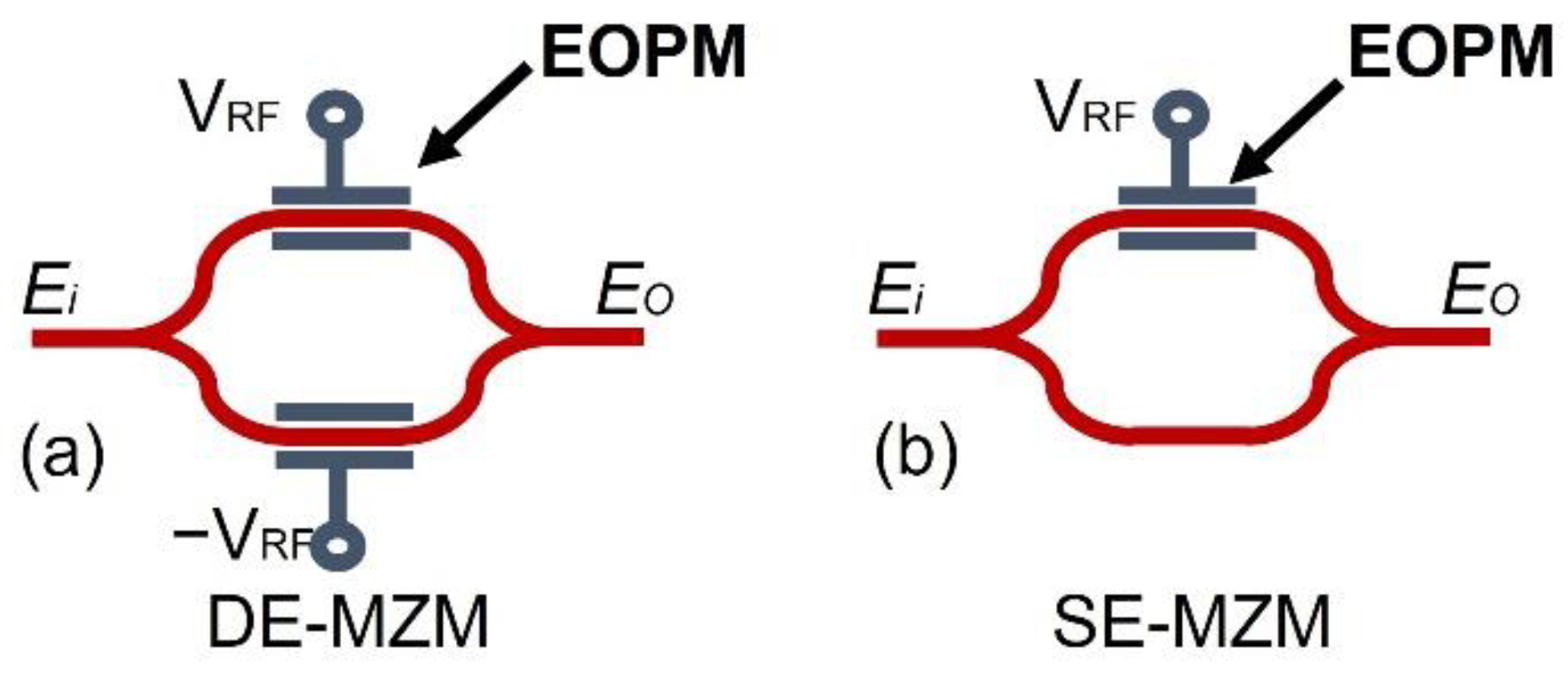
A Mach-Zehnder Modulator (MZM) is a Mach-Zehnder Interferometer, which is composed of two EOPM (i.e., Double EOPM-MZM) or just one (i.e., Single EOPM-MZM). These structures are illustrated in Figure 1. To modify the phase of the propagating light, it harnesses the electro-optic effect (or known as the Pockels Effect) of some materials, such as LiNbO3, GaAS, or InP. This effect linearly modifies the refractive index with an external electric field applied on a non-centrosymmetric crystal. In essence, when an external electric field is applied on the MZM, an 180° difference of phase between the two branches can be induced and the two incoming beams can destructively interfere. Ideally, this results in a nullified output field, but this cannot be achieved with current fabrication techniques. It is guaranteed that there will always be power remaining when a destructive interference condition is established on a real MZM. To reach a 180° phase shift, it requires a certain amount of voltage, defined as .
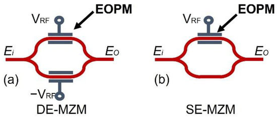
Figure 1.
(a) Double EOPM-MZM architecture (DE-MZM). Adding one EOPM operated with a signal 180° degrees of phase difference to that of the other EOPM enables push-pull operation with proper bias. This operation mitigates the chirp effect induced when the beam is phase modulated. (b) Single EOPM-MZM architecture (SE-MZM). This is the simplest Mach-Zehnder modulator structure to build and operate with one EOPM, but the chirp is not controlled. For push-pull operation, both EOPM must be biased on different operative points of the characteristic curve as the EOPMs work only with negative voltage.
In Equation (1), the output electric field of a DE-MZM is expressed, corresponding to the structure in Figure 1a. Here, an imperfect power splitting ratio for both splitters is considered. Assuming that the input and output couplers are identical, we can simplify the expression by using a power splitting ratio for both components. The voltage applied on the DE-MZM is the same, but with 180° of phase difference, as this will be driven in a push-pull manner. In Equation (2), the respective output electric field can be observed for the SE-MZM [13,14,15], as seen in Figure 1b.
where:
- : Is the voltage needed to reach a phase shift equal to π;
- : Is the RF voltage applied on the respective EOPM;
- : Coupler Splitting Ratio.
As can be seen in (1), we need just half of to reach the lowest value of the output electric field (i.e., when the argument of the exponentials is equal to π/2). On the other hand, we need to double the to reach the same condition in an SE-MZM (i.e., when the argument of the exponentials is equal to π). We can easily visualize those conditions by assuming a perfect power splitting ratio of 0.5. The presence of the imaginary part of the output electric field means an undesired phase shift, which is the cause of the spurious side bands in the spectrum when a clean amplitude modulation is intended. Additionally, more sidebands will appear if the optical beam is exposed to a more intense external electric field, since will proportionally increase the phase modulation index. This means that a goal of the design of a FS based on the MZM electro-optic effect is the reduction of the . If this parameter is low, the will sooner reach , and the peak phase deviation will be halved. Taking care with the PIC design to achieve lower will mean less spurious side bands in the spectrum.
In Equation (3), the expression of is shown, which is a parameter of MZMs that depends on material used for the waveguides and its geometry.
where:
- d: distance between conductors;
- : Vacuum operation wavelength;
- L: Length of the waveguide;
- r: Linear electro-optic coefficient;
- n: Refraction index with no electric field applied.
By increasing L, we can lower the required to induce a 180° phase shift; nevertheless, we should remember that longer waveguides on the MZM means an increase in the optical loss and a decrease of the modulation bandwidth caused by parasitic capacitance formed with the conductive material of the EOPM. In the design, should a preference persist on symmetric MZM to mitigate the unbalance of the power splitting ratio as the waves will travel the same length; hence, they will suffer the same propagation loss. If Asymmetric MZM are used, we require an amplifying block to compensate for the attenuation in the longest path.
3. Architecture of the DSB-SC Based OFS
3.1. Working Principle
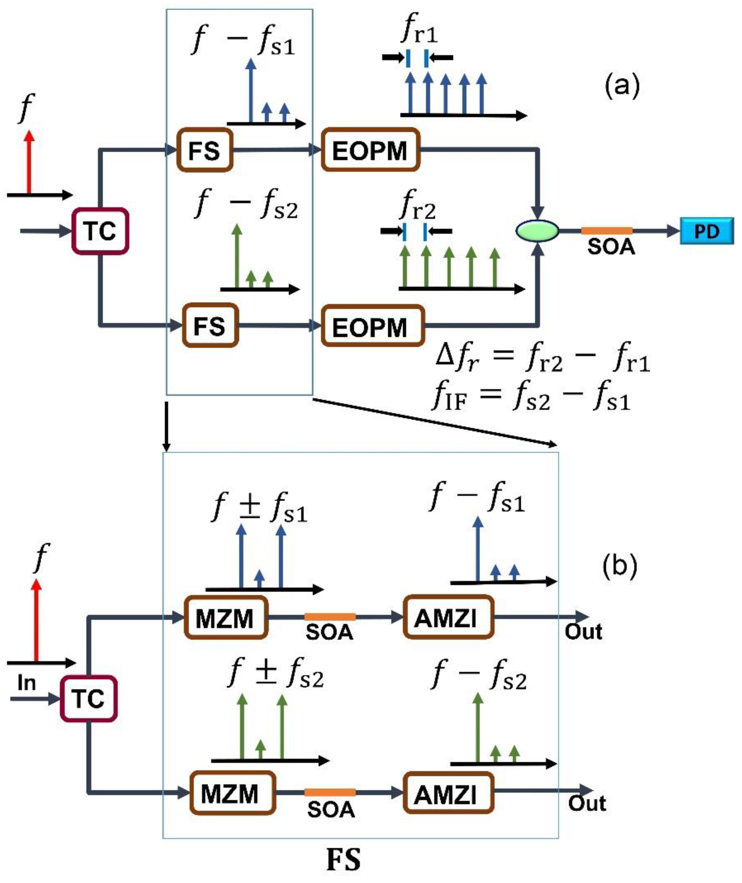
The FS is considered a key stage for an integrated dual comb generator. We justify this architecture, since we need to modulate the phase of two tones independently to generate a dual comb. Moreover, by operating the MZMs as DSB-SC modulators, the bias point and the required RF voltage are easy to find and, given that we need just one of the resulting sidebands, we can concentrate efforts to filter one of them and not a set of sidebands. The architecture designed also permits On-OFF Keying (OOK) modulation, or more complex modulation formats, to enable applications like THz or optical communications. In Figure 2, the architecture of the FS is depicted. Among the stages, the MZMs are the key components to compare when SE-MZM and DE-MZM structures are implemented.
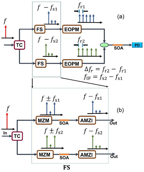
Figure 2.
(a) System architecture, including the comb generator stage using two phase modulators. (b) Zoom into Frequency shifter stage. The spectral behavior is described stage by stage. Both MZMs (Mach-Zehnder Modulators) are operated with RF driving frequencies equal to and . The difference between these frequencies will be the IF frequency , where the shrunken comb will be centered. These frequencies should be high enough to ease the filtering with the FSR (Free Spectral Range) of the AMZI (Asymmetric Mach-Zehnder Interferometer). The AMZIs are tuned with a DC voltage until it filters one of the sidebands that both MZMs deliver. The EOPMs (Electro-Optic Phase Modulator) on the comb generation stage are driven with RF voltages equal to and . The difference between these two repetition frequencies will be the repetition of the shrunken comb equal to . Since we need to generate a dual comb, the phase modulators for comb generation should be just after the frequency shifter stage. If a simple electro-optic frequency shifter or an electro-optic modulator for telecommunications is required, we can disable one branch by tuning the TC (Tunable Coupler) to direct the beam through one of the optical paths and leave the EOPM free, with no modulation applied. SOAs (Semiconductor Optical Amplifiers) are utilized to compensate for losses and to absorb the power remaining of the disabled branch.
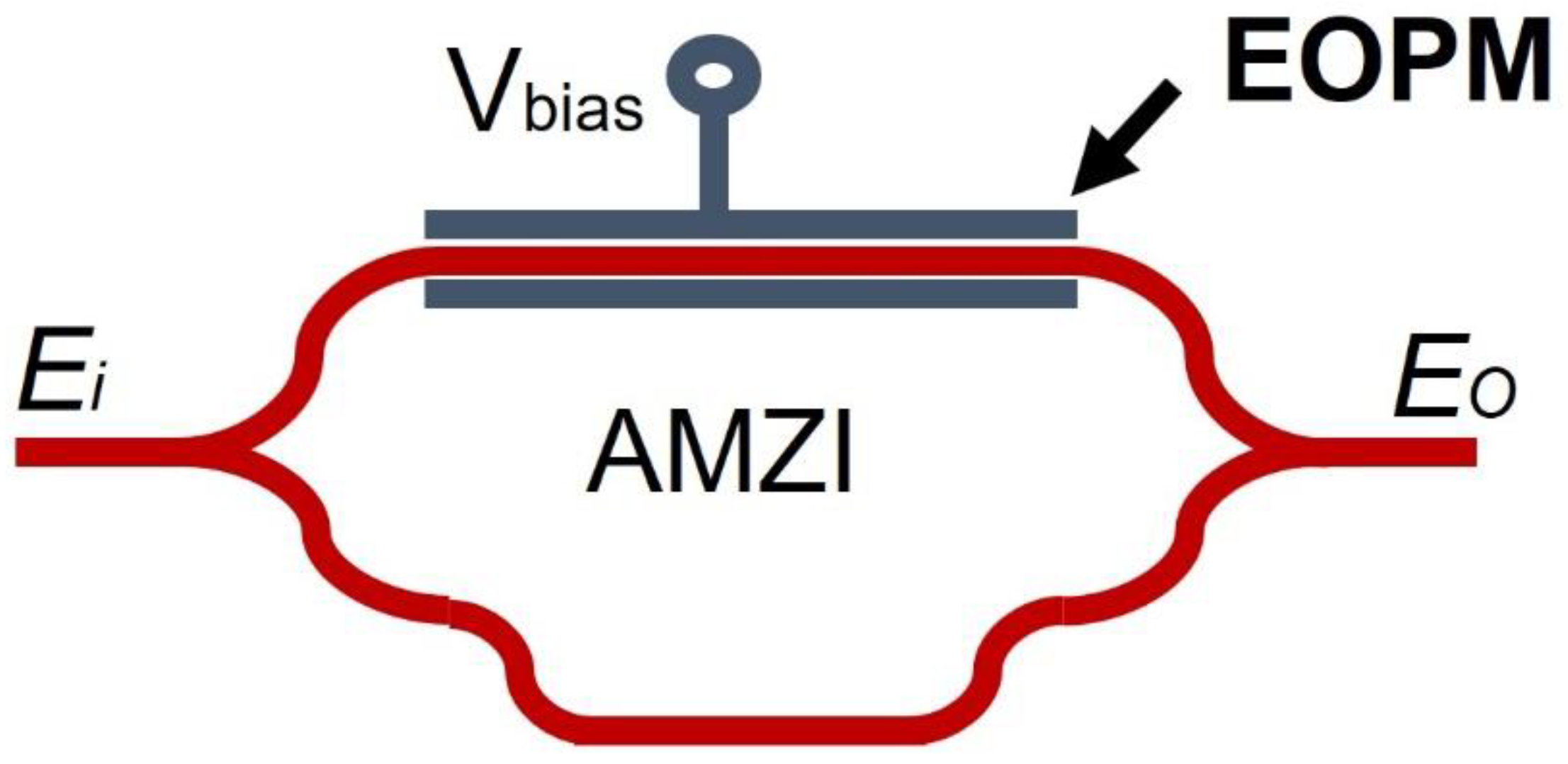
An incoming optical beam enters the TC (Tunable Coupler), which can be tuned to direct the power to just one of the paths. This is implemented to operate the FS as a simple electro-optic frequency shifter, the operating frequency of which can reach the order of GHz. In this operating mode, using a frequency to modulate the MZMs, we can beat the optical signal to get an IF frequency corresponding to . In the same manner, instead of using a single tone with frequency , we can use data to externally modulate the input optical signal for telecommunications. On the other hand, if we need to generate a dual comb, the TC is tuned to have a power splitting ratio of 0.5. Next, the light is modulated by an MZM in both branches with different frequencies and , and the difference will be equal to the intermediate frequency . In the case of the SE-MZM, the MZM is biased at the lowest operation point on its characteristic curve to execute a DSB-SC modulation (i.e., a voltage where a minimum optical power is obtained at the output). In the case of DE-MZM, to enable push-pull operation, the bias of each EOPM is chosen in the middle between a maximum and a minimum, and the other is in the middle of a minimum and a maximum. By modulating each EOPM with two tones with the same frequency but with a phase difference of 180°, one EOPM will increase its refractive index, while the other one will decrease it. In this manner the light on each branch will reach destructive interference sooner than in the case of SE-MZM. The SOAs are placed to compensate for the power of the sidebands after modulation. The AMZIs are used to filter one of the two resulting sidebands. The structure of the AMZI is depicted in Figure 3. This is a simple tunable filter where we can tune the central frequency by applying a DC voltage on an EOPM. The FSR (Free Spectral Range) is given by , where is the light speed in vacuum and is the optical path length difference between the two branches given by . and are the refractive indexes of each one of the optical paths, and one of them is modified with a voltage applied to the EOPM. The AMZI is tuned in a way that the desired sideband is on the passband range, and the other on the rejection band.
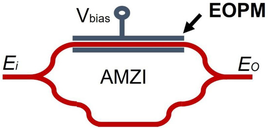
Figure 3.
AMZI: Asymmetric Mach-Zehnder Interferometer. EOPM: Phase Modulator. The FSR depends on the length difference between the two paths. By applying voltage on the EOPM, we can adjust the central frequency of the filter. This is an optical filter with a simplified structure and operation.
Practical PIC filters are limited by their FSR, which are in the order of GHz. If we want to filter one sideband without affecting the other, we need to use a frequency on the DSB_SC modulator in the same order as practical or realizable optical filters (i.e., FSR around 5 GHz or more). After the AMZIs are placed, two EOPM are operated by two tones with slightly different frequencies and . When these two combs beat each other, we will obtain a copy of the comb in the electrical domain centered in , with a repetition frequency given by . Given the decrease in the optical power on the comb lines, in the output of the PMs, it is placed on an SOA after each EOPM to amplify the signals. Each one of the SOAs are dimensioned with 200 µm long, and biased with 120 mA. It should be noted that MZMs and EOPMs will operate with greater modulation bandwidth if we induce a copropagating RF signal with the optical signal, as this approach exposes the light even more to the changes of the [16].
3.2. Results
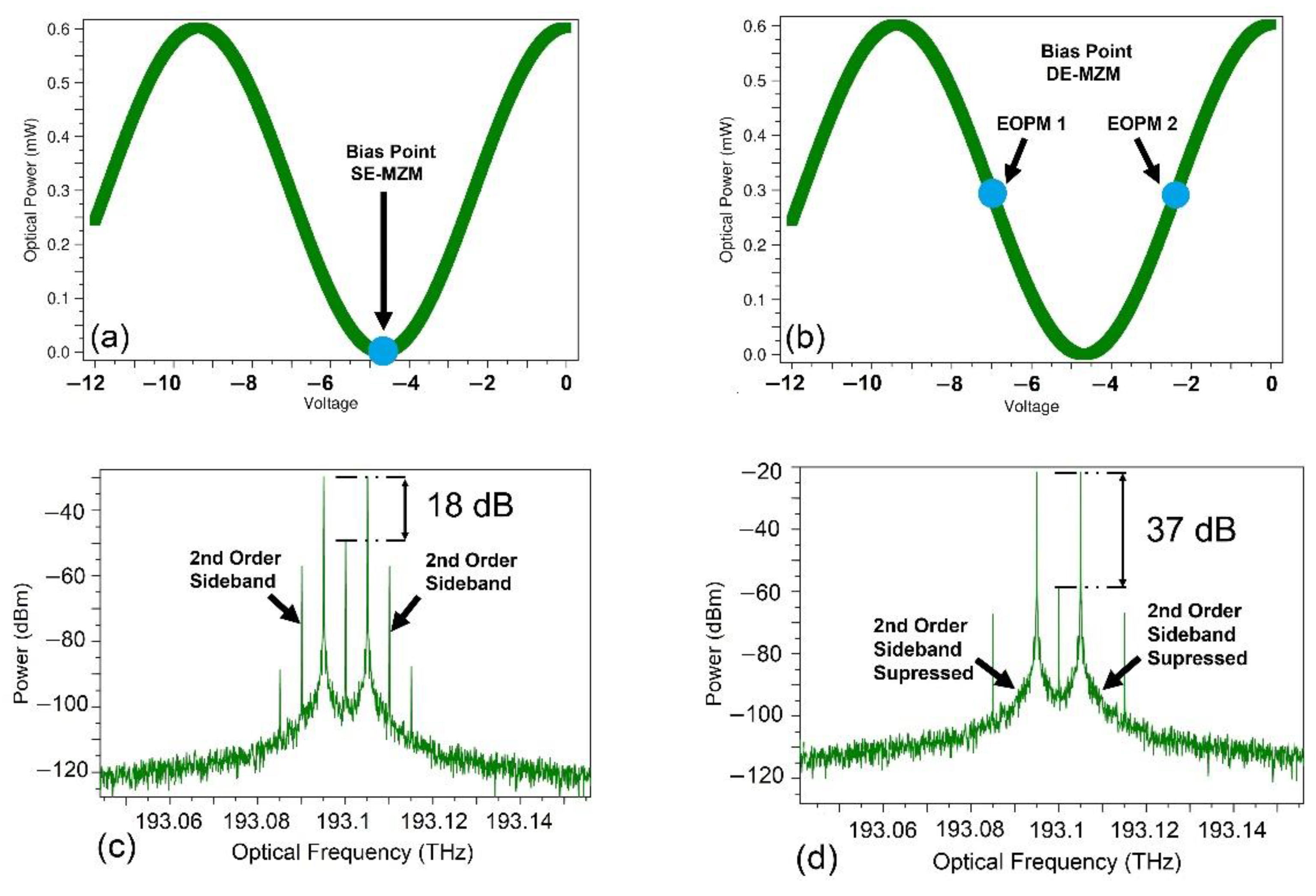
We used Synopsys OptSim simulation software and a Process Design Kit (PDK) of an InP technology foundry. The EOPM used on all the system stages was specified to be 2 mm long and driven by an RF signal, with an amplitude equal to 1.25 V. With this length, we obtained (See Figure 4a). Since this parameter was inversely proportional to the waveguide length, according to Equation (3), we could reduce this parameter if needed. The operation frequency used was 5 GHz on the upper branch and 5.001 GHz on the bottom branch. If these signals beat each other on a photomixer, this will result in an electrical signal centered in . We optimized the bias point of the DE-MZM to enable push-pull operation (see Figure 4b) to obtain a DSB-SC spectrum (see Figure 4d). It should be noted that carrier suppression (CS) was improved when using two EOPMs. In this case, the CS was approximately 37 dB. On the other hand, when using only one EOPM, the CS was 18 dB. Moreover, the spurious sidebands were highly suppressed with two EOPMs, and the second order sidebands were nullified. Given these results, we noted that a cleaner spectrum could be obtained if we built an MZM with two EOPMs and operated in a push-pull manner.
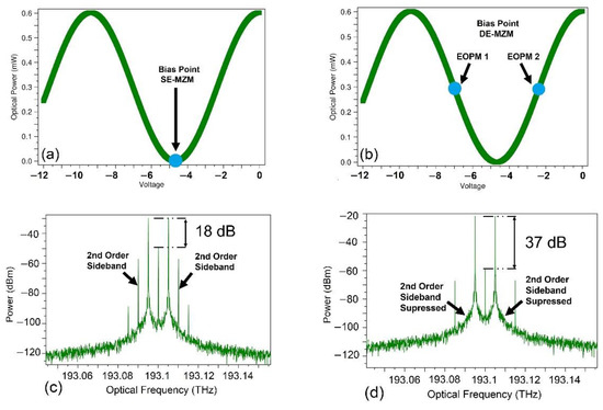
Figure 4.
(a) Characteristic curve of the SE-MZM structure. (b) Characteristic curve of the DE-MZM structure. (c) DSB-SC spectrum of the SE-MZM approach. (d) DSB-SC spectrum of the DE-MZM approach.
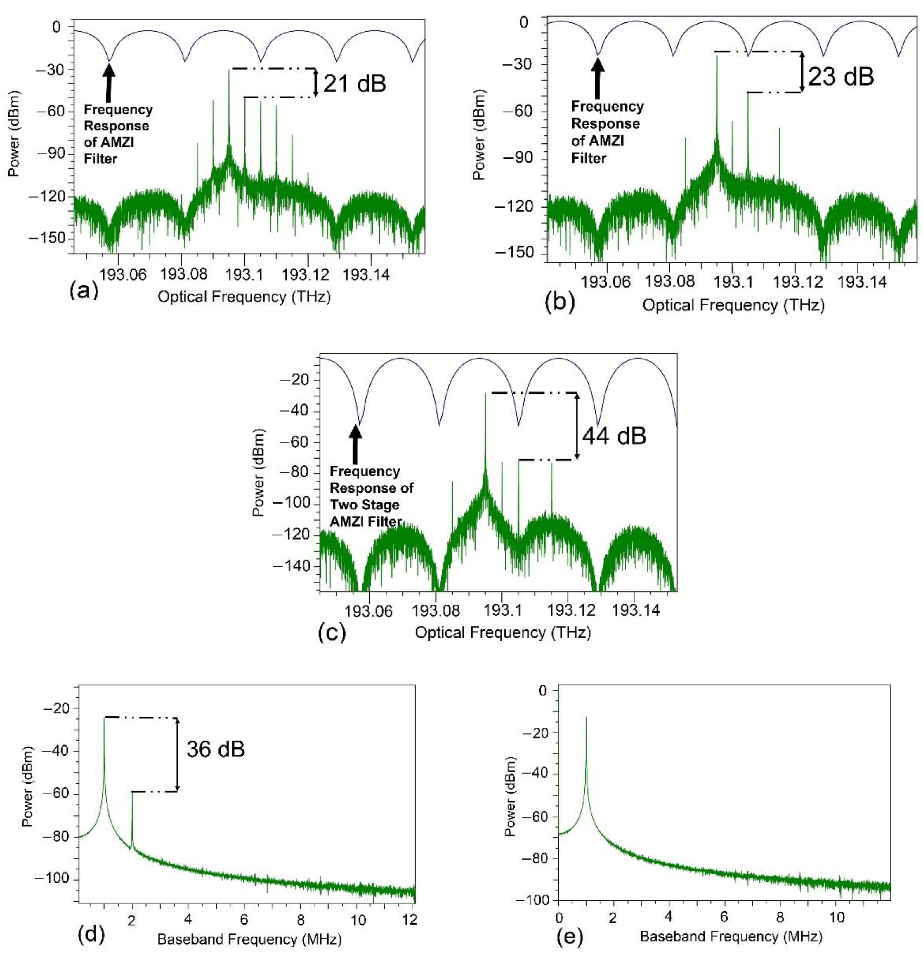
After the optical carrier was modulated, the optical signal was filtered by the AMZI and the Free Spectral Range FSR was 32.8 GHz. To achieve this FSR, the length difference of the waveguides composing the AMZI was 3 mm and a group index of was provided by the foundry specifications. The EOPM on the AMZI was tuned until the sideband rejection was maximized. The carrier suppression acquired was greater because it was standing right in the transition and rejection band of the filter. These results are depicted in Figure 5. For the DE-MZM approach, the SMSR reached 23 dB and the CS was 41 dB. For the SE-MZM approach, the CS and SMSR were approximately 21 dB. We also tested the possibility of using a second cascaded AMZI, and we reached an SMSR and CS near to 44 dB. This is shown in Figure 5c. We mixed the two shifted tones in both structures, and we obtained a spurious tone in the case of the SE-MZM. This was due to the presence of the second order sidebands of the upper and lower FS stages after DSB-SC modulation (see Figure 4c,d), since the difference between them was 2 MHz. This tone did not appear in the case of DE-MZM, given that the second order sidebands were completely attenuated because of the push-pull operation.
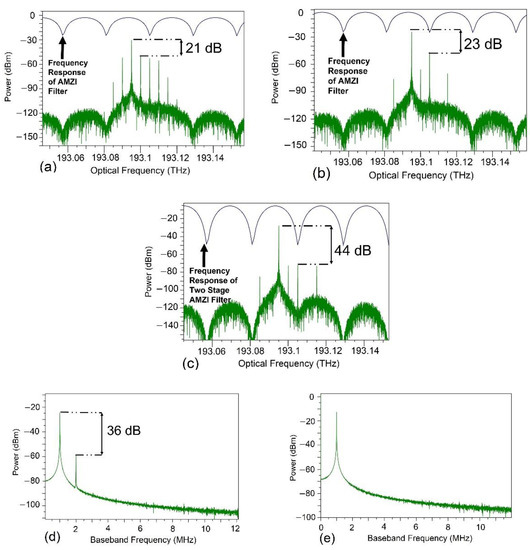
Figure 5.
Frequency shift effect. SMSR after filter. (a) SE-MZM output optical spectrum. (b) DE-MZM output optical spectrum. (c) DE-MZM output optical spectrum filtered with two cascaded AMZI filters. (d) SE-MZM electrical spectrum of , SMSR=36 dB. (e) DE-MZM electrical spectrum of .
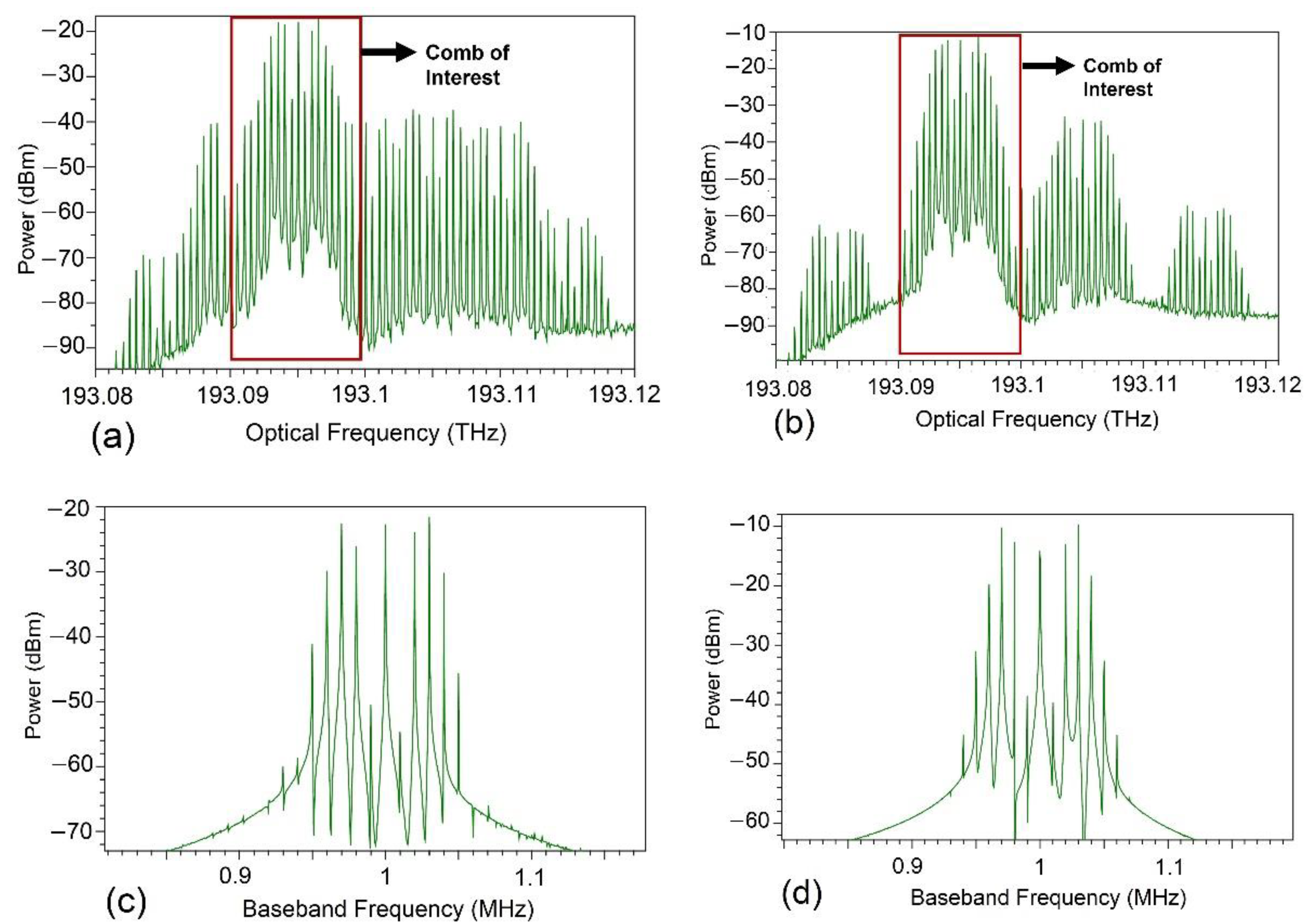
Once the frequency shift effect was produced, we proceeded to generate an optical frequency comb by modulating the phase of the incoming signal with the EOPMs. We drove the EOPMs with , and with a DC offset of −6 V. The EOPM building block of the foundry was 12 V with 2 mm long waveguides. The frequency applied on each of the EOPMs was 500 MHz and the other with 500 MHz + 10 kHz. The resulting comb signal in the electrical domain obtained a repetition frequency of 10 kHz, and was centered on 1 MHz. The PIN photodetector used to downconvert the signal was configured to have a dark current of 1 µA, and a responsivity of 0.8 A/W. RIN. Shot and spontaneous emission noises were enabled to get close to real conditions. The corresponding combs in the optical and electrical domain for the DE-MZM and SE-MZM approaches are depicted in Figure 6. We counted eleven significative comb lines, which meant optical comb spans around 5 GHz and, in the case of the electrical comb, the span was 100 kHz. Given that there were a large number of mixing products on the photodetector, optical sidebands with low power could not be observed, since the corresponding electrical power was too low. We counted those comb lines in the middle as significant, since we could modify the spectral flatness with the RF voltage applied on the EOPMs.
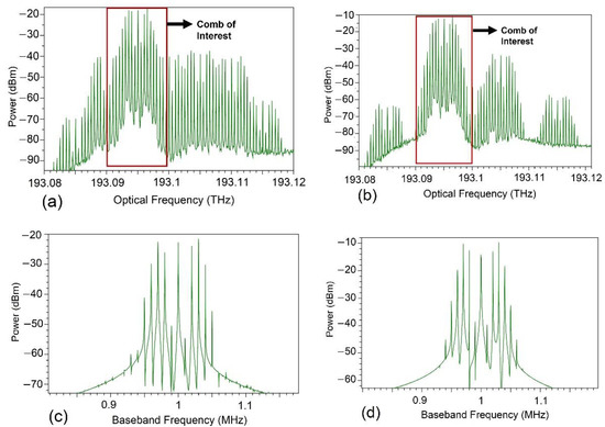
Figure 6.
(a) Optical Dual-Comb with SE-MZM. (b) Optical Dual-Comb with DE-MZM. (c) Comb in IF frequency, centered at 1 MHz when operated with the SE-MZM approach. (d) Comb in IF frequency, centered at 1 MHz operated with the DE-MZM approach. Each one of the spurious sidebands obtained with DSB-SC modulation has a comb associated after they pass through the EOPM. In the case of DE-MZM, the combs are more separated than in the case of the SE-MZM. This means that all the mixing products are also far apart from the main set in the case of the DE-MZM approach. It can be observed that the DE-MZM structure offers an IF comb with more power (10 dB more than in the case of SE-MZM).
In the case of the DE-MZM operation, the spurious sidebands after the frequency shifter stage had less power than in the case of SE-MZM. When the frequency shifter output was phase modulated to generate a comb, we obtained several comb subsets related to every sideband remaining after the frequency shift process. With DE-MZM, we obtained optical combs more detached from the main comb than in the case of SE-MZM. This was necessary, as we did not want the comb subsets to overlap. With SE-MZM, the spurious combs were tightly attached to the main comb, encouraging an increased number of comb line mixing products. This means that the mixing products after the photodetection were reduced with the DE-MZM approach compared to the SE-MZM operation. Moreover, every spurious tone mixed with others, but with less energy in the DE-MZM; thus, the IF comb receives greater power and a cleaner spectrum. This result can be contrasted with Figure 5e, as the frequency-shifted signal was just a single tone in the neighborhood of the IF frequency.
4. Discussion
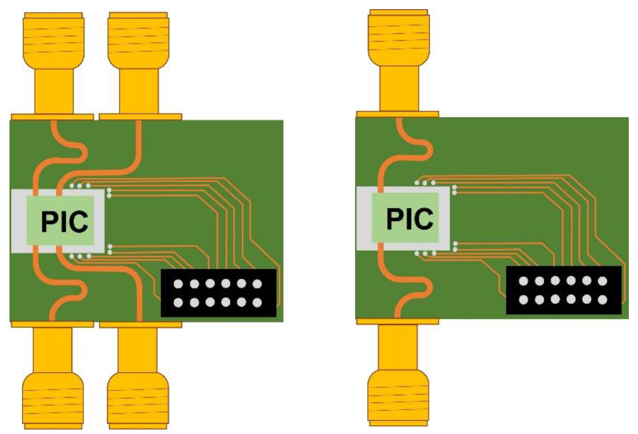
According to the results, there is a significant improvement in the frequency shifter architecture if DE-MZM operation is chosen. Another important advantage is that spurious sidebands are highly reduced, which implies a cleaner spectrum. Nevertheless, the complexity of the overall system must be considered. For instance, by adding two EOPMs for push-pull operation means adding two additional RF ports (see Figure 7). Comparing the packaging and the output signals for both architectures, it is worth choosing the DE-MZM approach, given the benefits. On the other hand, for applications like spectrometers, this is not an option since a suppressed sideband is always preferred for precise measurements.
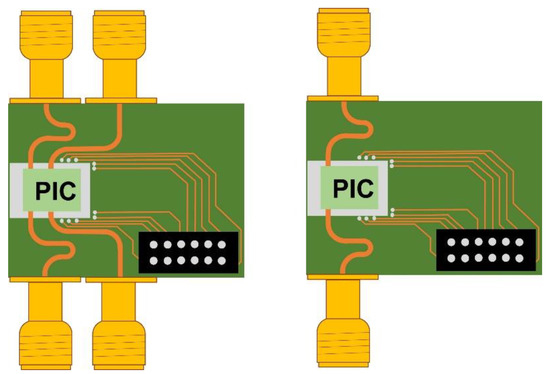
Figure 7.
On the black port, there will be DC signals. The electrical waveguides for the RF signals should have the same length on the respective MZM; otherwise, phase will need to be adjusted. (Left) Packaging of the DE-MZM FS. (Right) Packaging of the SE-MZM FS. In this representation, we are not including the RF ports for the EOPM used for comb generation.
One feature that must be considered is the reduced power of the comb centered in . The dual comb technique is relevant, since it opens up the possibility of real time absorption fingerprint identification for sample materials; however, we should mention that one of the key drawbacks is that we obtained a copy of the optical comb but with a reduced power. This was given for all the mixing products produced after the two optical combs mixing with each other on a photomixer. As a result, we obtained several copies of the main optical comb in the electrical domain repeating every multiple of . This is depicted in Figure 8. From the perspective of a THz detector, if we use one with a high sensitivity—meaning a low video bandwidth THz detector—higher order combs will be filtered. However, in the case of a THz detector with bigger video bandwidth, it will possibly detect the comb with low-cost RF systems (e.g., AD9361 RFIC or LMS7002M), which can process signals with the concept of Software Defined Radio. This concept gives way to applications such as cognitive spectrometers, where disturbed signals can be intelligently processed with state-of-the-art artificial intelligence techniques.

Figure 8.
A radiography of the electrical spectrum after the dual comb is mixed. is the frequency shift applied in the FS stage, which is 1 MHz. is the repetition frequency difference between the two RF signals applied on the comb generation stage (the two EOPM after the FS). In this case, . is the repetition frequency of the RF signals applied in the comb generation stage. In this case, .
Using InP technology for PIC provides some degree of freedom in overcoming the optical losses inside the chip, and allows the possibility of adding SOAs as needed. This presents the choice of connecting another AMZI stage to improve the SMSR, which means a cleaner spectrum. However, the complexity of this case should also be considered given that every SOA requires a source current.
5. Conclusions
This study investigated a photonic-integrated frequency shifter. The results showed an improvement of the system by evaluating the DE-MZM approach with the purpose of improving the CS and the SMSR. The push-pull operation mitigates the chirp on the signal, and this engenders highly suppressed spurious sidebands, providing 10 dB more power on the comb compared to the SE-MZM structure. We can exclude the AMZI stage if a single tone is needed on the application, but in the case of dual combs, it is mandatory since we need to independently modulate two optical signals with slightly different frequencies. We hope that the fabrication imperfections of the PIC will not inflict a strong impact on the splitting ratio of the MZMs; nevertheless, we consider the use of SOAs able to compensate for the power difference on the MZMs. Otherwise, it leads to the presence of unwanted sidebands.
Adding a second AMZI stage is promising, but as was discussed earlier, adding more electrodes and current sources to compensate for the optical losses should be considered. Moreover, if this system was fabricated in an MPW (Multi-Project Wafer), the available area would need to be revised. We used a PIN detector to show the behavior of the signal in IF frequency; however, we believe that a photoconductive antenna or state-of-the-art photomixer will do a better job in terms of energy conversion for THz applications.
Author Contributions
A.B.-P.: Simulations of the PIC Frequency Shifter, laboratory measurements of THz, Dual-Combs, paper writing and state of the art study. C.d.D.: Assessment of the THz system. P.A.: Research Project Management. All authors have read and agreed to the published version of the manuscript.
Funding
This research was supported by Instituto Tecnológico Metropolitano under the project P21101 “Fortalecimiento y Consolidación del Grupo Automática, Electrónica y Ciencias Computacionales para Responder a las Necesidades de las Industrias 4.0”. This work was also supported by Universidad Carlos III de Madrid, the EU H2020 Celta project under Grant Agreement 675683, by the Spanish Ministry of Economy and Competitiveness under Project TEC2017-86271-R and by the ATTRACT project funded by the EC under Grant Agreement 777222.
Institutional Review Board Statement
Not applicable.
Informed Consent Statement
Not applicable.
Acknowledgments
We thank to the information system staff to keep the server and network working properly to execute the simulation software under the COVID-19 global health emergency.
Conflicts of Interest
The authors declare no conflict of interest.
References
- Langdon, R.J.; Yousefi, P.D.; Relton, C.L.; Suderman, M.J. A Bipolar, Two Component Laser-Doppler Velocimeter. J. Phys. E Sci. Instrum. 1975, 8, 729. [Google Scholar] [CrossRef]
- Yoshimura, T.; Syoji, Y.; Wakabayashi, N.; Suzuki, N. Optical Frequency Shifting for Rayleigh Scattering Spectroscopy (Laser Velocimeters). J. Phys. E Sci. Instrum. 1978, 11, 777–780. [Google Scholar] [CrossRef]
- Castellini, P.; Martarelli, M.; Tomasini, E.P. Laser Doppler Vibrometry: Development of Advanced Solutions Answering to Technology’s Needs. Mech. Syst. Signal Process. 2006, 20, 1265–1285. [Google Scholar] [CrossRef]
- Supradeepa, V.R.; Long, C.M.; Wu, R.; Ferdous, F.; Hamidi, E.; Leaird, D.E.; Weiner, A.M. Comb-Based Radiofrequency Photonic Filters with Rapid Tunability and High Selectivity. Nat. Photonics 2012, 6, 186–194. [Google Scholar] [CrossRef]
- Lu, H.H.; Lukens, J.M.; Peters, N.A.; Odele, O.D.; Leaird, D.E.; Weiner, A.M.; Lougovski, P. Electro-Optic Frequency Beam Splitters and Tritters for High-Fidelity Photonic Quantum Information Processing. Phys. Rev. Lett. 2018, 120, 30502. [Google Scholar] [CrossRef] [PubMed]
- Yoo, S.J.B. Wavelength Conversion Technologies for WDM Network Applications. J. Light. Technol. 1996, 14, 955–966. [Google Scholar] [CrossRef]
- Barretto, E.C.S.; Hvam, J.M. Photonic Integrated Single-Sideband Modulator/Frequency Shifter Based on Surface Acoustic Waves. Silicon Photonics Photonic Integr. Circuits II 2010, 7719, 771920. [Google Scholar] [CrossRef]
- Shao, L.; Sinclair, N.; Leatham, J.; Hu, Y.; Yu, M.; Turpin, T.; Crowe, D.; Loncar, M. Integrated Lithium Niobate Acousto-Optic Frequency Shifter. Opt. InfoBase Conf. Pap. 2020, 6–7. [Google Scholar] [CrossRef]
- Spuesens, T.; Li, Y.; Verheyen, P.; Lepage, G.; Balakrishnan, S.; Absil, P.; Baets, R. Integrated Optical Frequency Shifter on a Silicon Platform. In Proceedings of the 2016 Conference Lasers Electro-Optics, CLEO 2016, San Jose, CA, USA, 5–10 June 2016; Volume 2, pp. 3–4. [Google Scholar] [CrossRef]
- Sueta, T.; Shikama, S. Integrated Optical SSB Modulator/Frequency Shifter. IEEE J. Quantum Electron. 1981, 17, 2225–2227. [Google Scholar] [CrossRef]
- Lauermann, M.; Weimann, C.; Knopf, A.; Heni, W.; Palmer, R.; Koeber, S.; Elder, D.L.; Bogaerts, W.; Leuthold, J.; Dalton, L.R.; et al. Integrated Optical Frequency Shifter in Silicon-Organic Hybrid (SOH) Technology. Opt. Express 2016, 24, 11694. [Google Scholar] [CrossRef]
- Betancur-Pérez, A.; Martín-Mateos, P.; de Dios, C.; Acedo, P. Design of a Multipurpose Photonic Chip Architecture for Thz Dual-Comb Spectrometers. Sensors 2020, 20, 6089. [Google Scholar] [CrossRef]
- Anon. PASSIVE OPTICAL COMPONENTS. Electro-Opt. Syst. Des. 1974, 6. [Google Scholar] [CrossRef]
- Hui, R.; O’Sullivan, M. Basic Instrumentation for Optical Measurement. Fiber Opt. Meas. Tech. 2009, 129–258. [Google Scholar] [CrossRef]
- Kaminow, I.P.; Koch, T.L. Optical Fiber Telecommunications IIIB. Opt. Fiber Telecommun. IIIB 2012, B, 1–515. [Google Scholar] [CrossRef]
- Akiyama, S.; Itoh, H.; Sekiguchi, S.; Hirose, S.; Takeuchi, T.; Kuramata, A.; Yamamoto, T. Inp-Based Mach—Zehnder Modulator With Capacitively Loaded Traveling-Wave Electrodes. J. Light. Technol. 2008, 26, 608–615. [Google Scholar] [CrossRef]
Publisher’s Note: MDPI stays neutral with regard to jurisdictional claims in published maps and institutional affiliations. |
© 2022 by the authors. Licensee MDPI, Basel, Switzerland. This article is an open access article distributed under the terms and conditions of the Creative Commons Attribution (CC BY) license (https://creativecommons.org/licenses/by/4.0/).

