Abstract
Hydrolysis of light metals and hydrides can potentially be used for the generation of hydrogen on-board fuel cell vehicles, or, alternatively, for refilling their fuel tanks with H2 generated and pressurised without compressor on site, at near-ambient conditions. Implementation of this approach requires solution of several problems, including the possibility of controlling H2 release and avoiding thermal runaway. We have solved this problem by developing the apparatus for the controlled generation of pressurised H2 using hydrolysis of Mg or MgH2 in organic acid solutions. The development is based on the results of experimental studies of MgH2 hydrolysis in dilute aqueous solutions of acetic, citric, and oxalic acids. It was shown that the hydrogen yield approaches 100% with a fast hydrolysis rate when the molar ratio acid/MgH2 exceeds 0.9, 2.0, and 2.7 for the citric, oxalic, and acetic acids, respectively. In doing so, the pH of the reaction solutions after hydrolysis corresponds to 4.53, 2.11, and 4.28, accordingly, testifying to the buffer nature of the solutions “citric acid/magnesium citrate” and “acetic acid/magnesium acetate”. We also overview testing results of the developed apparatus where the process rate is effectively controlled by the control of the acid concentration in the hydrolysis reactor.
1. Introduction
Use of hydrogen as an energy carrier is the most promising solution to address the energy and environment issues and to meet future energy needs. Energy systems based on hydrogen fuel cells are characterised by high efficiency and power density, and are presently used in many stationary and mobile applications [1,2,3,4]. The main issue that hinders further implementation of hydrogen fuel cell technologies is the need of compact, safe, and efficient hydrogen storage. Along with various methods of reversible hydrogen storage based on physical processes (compression and liquefaction) and the use of hydrogen storage materials (high-surface area adsorbents, hydrides, liquid organic hydrogen carriers, etc.) [5], special attention has been recently paid to on-site (or on-board) hydrogen generation by the hydrolysis of various light-weight materials such as ammonia borane [6,7], sodium, lithium and magnesium borohydrides [8,9,10,11], aluminium [9,12] or alloys/composites on its basis [13], magnesium and magnesium alloys [9,14,15,16,17,18], magnesium hydride [9,15,19,20,21,22,23], and so on. These materials can undergo hydrolysis at near-ambient conditions, in alkaline, acidic, or neutral media, and frequently in the presence of a catalyst. A comprehensive review on the topic (289 references) has been recently published by Ouyang et al. [24].
Hydrogen generation by hydrolysis allows the mitigation of the hydrogen storage challenge by a simple and efficient way. Apart from compact storage in the form of the hydrogen-generating material with a possibility of on-demand H2 supply to a consumer (e.g., fuel cell using water vapour released during its operation), the feasibility of hydrolysis for the generation of hydrogen at the pressure up to 300 bar has been demonstrated [25]. This opens an opportunity to refill gas cylinder fuel tanks on board fuel cell vehicles with H2 generated and pressurised without an on-site compressor, at near-ambient conditions.
The practical implementation of hydrolysis for hydrogen generation still requires the solution of several problems, including (i) irreversibility of the hydrolysis reaction and high costs for the regeneration of its products, (ii) suppression of the side reactions (particularly dangerous for the boron-containing compounds when a toxic diborane can appear), (iii) improvement of the reaction kinetics, and, at the same time, (iv) the possibility of controlling H2 release depending on the customer need. Therefore, looking for a practical technology to generate hydrogen by hydrolysis remains a keen focus of research all over the world.
Magnesium is an inexpensive and readily available metal, which is abundant in the Earth’s crust (2.4%) and not harmful to the environment. Therefore, Mg or MgH2 can be considered as suitable candidate materials for hydrogen generation by hydrolysis [15,26]. Both magnesium and magnesium hydride are stable if they do not make contact with moisture; so, they can be stored for a long time and are safe during transportation.
Interaction of Mg and MgH2 with water is a highly exothermic reaction producing hydrogen gas and magnesium hydroxide [24]:
Mg + 2H2O → Mg(OH)2 + H2 + 354 kJ
MgH2 + 2H2O → Mg(OH)2 + 2 H2 + 277 kJ
The hydrolysis of MgH2 (Reaction 2) has a high theoretical hydrogen yield, 15.2 and 6.4 wt.%, without and with, accounting for the weight of water, respectively. This is almost double the amount of H2 generated by hydrolysis of individual Mg (Reaction 1; 8.2/3.3 wt.%).
Though the hydrolysis of MgH2 starts immediately when in contact with water, it is quickly interrupted by the formation of a passive magnesium hydroxide layer, which prevents further diffusion of water molecules to the surface of MgH2 particles. As a result, the hydrolysis of Reaction 2 is quickly stagnated and stops when the H2 yield achieves 10–20% of the theoretical one. Various methods were suggested to improve the performance of the process. The most frequently applied method relates to ball milling (or, more generally, mechanical activation) of MgH2 with catalytic additives [26,27,28,29,30]. Other methods include ultra-sonification [31], alloying the pristine magnesium with other elements [15], and the use of alcoholysis instead of hydrolysis [32].
Another approach to the acceleration and the increase in yield of the hydrolysis reaction is in the use of salts, e.g., sodium, potassium, aluminium, or magnesium chlorides, either added into aqueous solution or pre-mixed with magnesium hydride [33,34]. It was assumed that dissolution of the salt during hydrolysis disintegrates the Mg(OH)2 passive layer, thus promoting further interaction between MgH2 and water. The origin of this effect may be in the changes of ion exchange equilibria in the reaction solution which, in turn, may result in the changes of morphology of the Mg(OH)2 layer. As it was shown by Berezovets et al. [35], the presence of MgCl2 in the solution results in the increase in size of Mg(OH)2 critical nuclei to form an inhomogeneous layer on the surface of MgH2 particles, thus facilitating the diffusion of water molecules towards it. According to ref. [36], the maximum hydrogen evolution rate strongly depends on the method of introducing halides: the maximum rate of the hydrolysis of the mechanically treated mixtures of MgH2 with NaCl, MgCl2, NH4Cl, and NH4Br was found to be higher than the one observed during the interaction of MgH2 with their solutions while the hydrogen yield does not depend on the method of introducing the salts. The acceleration of hydrolysis was also associated with the evolution of heat when a salt is dissolved.
Bronsted acids, i.e., aqueous solutions of acids or ammonium salts, have been suggested for the disintegration or complete removal of the Mg(OH)2 passive layer during hydrolysis of MgH2 [37,38,39]. The acids should satisfy the following requirements: (i) their magnesium salts should be soluble in water, (ii) the acidic solution should not cause corrosion of hydrogen generation apparatus, (iii) the vapours of acids should not be released together with the generated hydrogen, and (iv) the acids and their magnesium salts should be non-toxic and environmentally friendly.
Solid organic acids, including glycolic, malonic, citric, and succinic acids, mostly satisfy the above-mentioned requirements. Additionally, their anhydrides and esters, which can transform into acids when interacting with water, can be used. As an example, the authors of patent [40] suggested the generation of hydrogen by the hydrolysis of a paste containing MgH2 powder and at least one aprotic organic substance with at least one carboxylic acid ester group. However, to avoid the passivation effect when using such substances as additives to MgH2, their amounts should be rather high.
Apart from the optimisation of the MgH2-based materials towards an increase in the yield and rate of the hydrolysis reaction, special attention in the process development has been paid to providing the efficient reaction control via various material and engineering solutions. Some examples are presented in patents [40,41,42,43,44,45]. A recently published article [46] outlined the main factors which can be used to control the reaction of MgH2 hydrolysis in acidic solutions, including the type of the acid, the rate of its supply to the hydrolysis reactor, as well as the pH of the solution. Similar results further elaborated in this article were presented by the authors earlier, in the conference paper [47]; further details can be found in the preprint [48].
We note that, due to the very high heat effects of hydrolysis Reactions 1 and 2, the upscale of hydrogen-generating processes based on them is associated with the high probability of thermal runaway which must be avoided. To achieve such an option, it is necessary to establish the influence of several factors (temperature of the reaction solution, concentration of the solute, pH, etc.) on the kinetics of the hydrolysis of Mg and MgH2, followed by suggesting efficient methods of their control, not only towards acceleration of the hydrolysis reaction (that is the subject of most of the published works on the topic) but also slowing it down when necessary. Our work contributes to filling this knowledge gap by the detailed quantitative studies of the influence of the type of the applied organic acid, its concentration in the solution, and the pH on the yield and rate of the hydrolysis reaction. The work is aimed at the development of simple and efficient technology for hydrogen generation by the hydrolysis of magnesium hydride. It is focused on the experimental study of the influence of commonly used organic acids (acetic, citric, and oxalic) in dilute aqueous solutions on the hydrolysis of commercial magnesium hydride powder. The results allowed us to identify the factors controlling reaction yield and kinetics and to develop a method and apparatus for generating pressurised H2 by the hydrolysis of the materials on the basis of Mg or MgH2 in acidic solutions [44].
2. Results and Discussion
2.1. Characterisation of Starting Material and Solid Residues after Its Hydrolysis
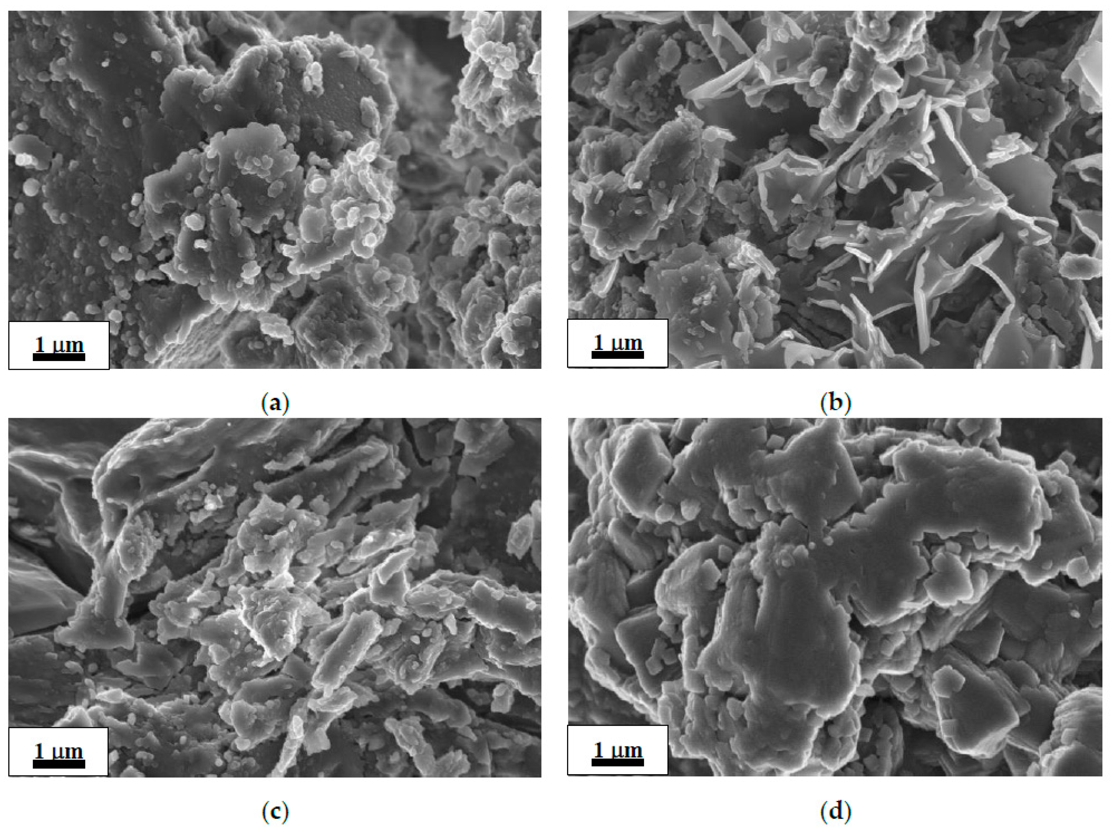
SEM images of the as-received commercial MgH2 and deposits after its hydrolysis in 1 wt.% aqueous solutions of organic acids are shown in Figure 1a–d. The morphology of the as-received MgH2 (Figure 1a) shows irregular and flaky particle orientation. The morphology of the residues after hydrolysis (Figure 1b–d) exhibits similar flake-like structure with a continuous smooth surface; the images show significant decrease in the number or complete disappearance of small (~0.1 μm) particles observed in the starting material (Figure 1a). The flakes observed in the residue after hydrolysis in the oxalic acid solution (Figure 1d) exhibited a noticeably bigger size than those in the residues after hydrolysis in the solutions of the acetic acid and citric acid (Figure 1b,c).
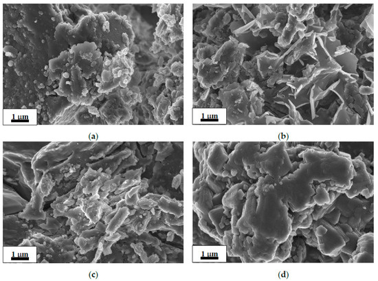
Figure 1.
SEM images of the as-received commercial MgH2 (a) and deposits after its hydrolysis in 1 wt.% organic acid solutions: acetic (b), citric (c), and oxalic (d).
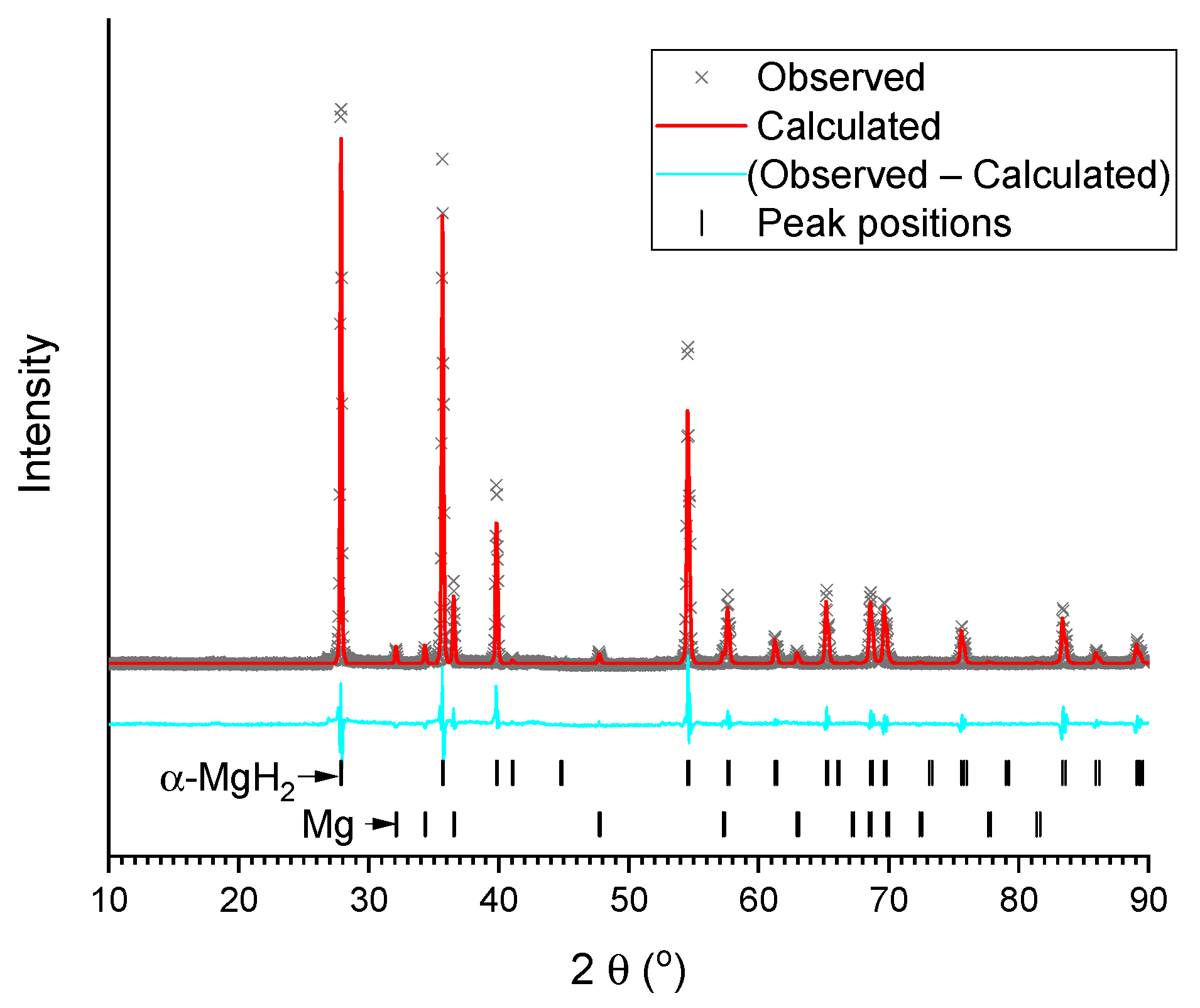
The refined XRD patterns of the studied samples are presented in Figure 2 and Figure 3a–d. The refinement results are summarised in Table 1. As can be seen, the as-delivered commercial MgH2 contains tetragonal rutile-type α-modification of magnesium hydride as a major phase, with the impurity (~9 wt.%) of metallic magnesium. Both phases are well-crystallised, and that is testified to by intensive and narrow peaks observed in the pattern (Figure 2).
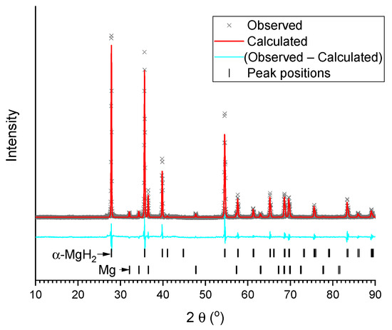
Figure 2.
Results of Rietveld refinement of XRD pattern of commercial MgH2 (background subtracted).
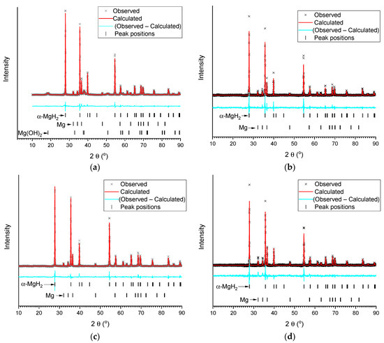
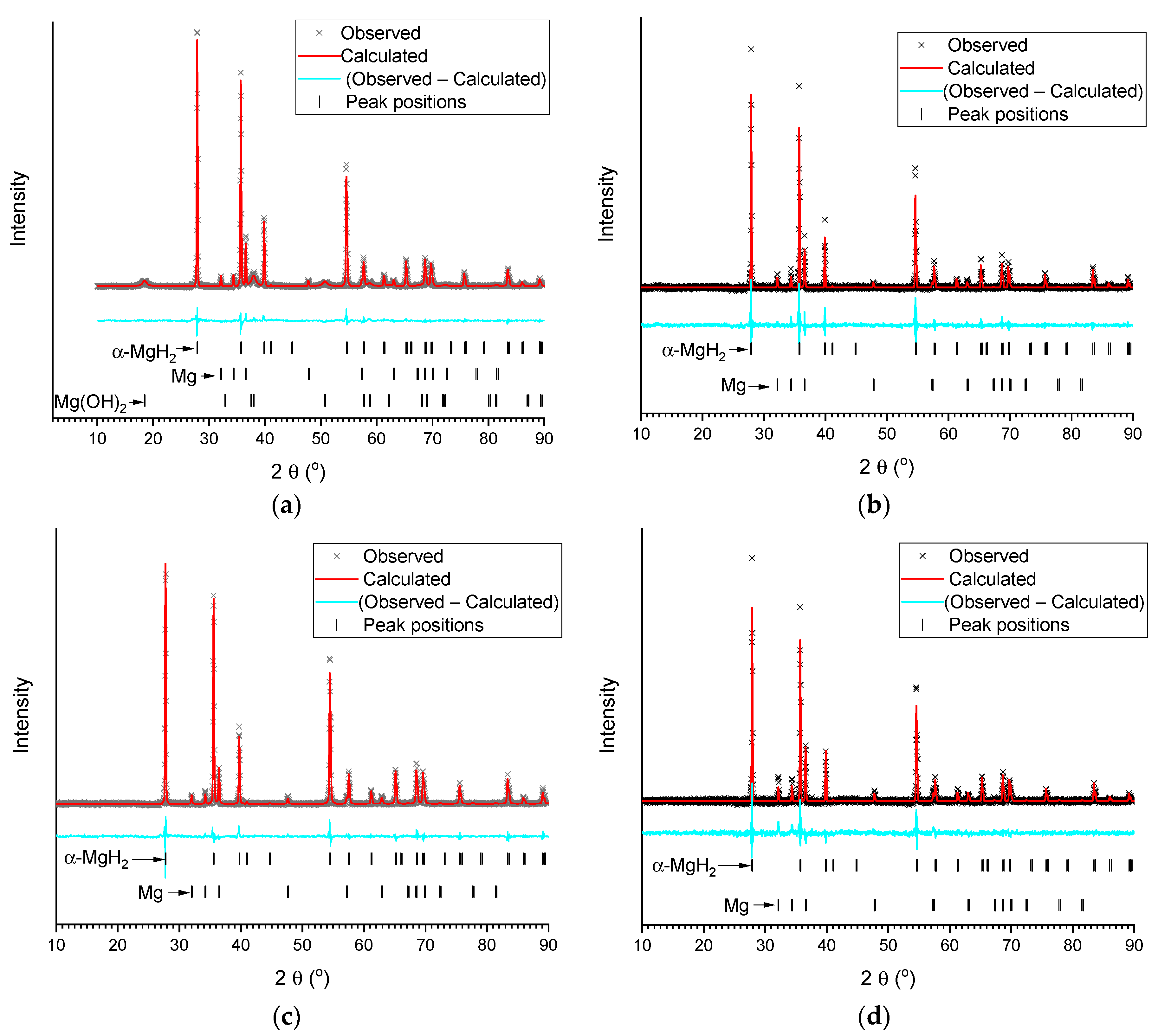
Figure 3.
Results of Rietveld refinement (background subtracted) of XRD patterns of the deposits after hydrolysis of MgH2 in deionised water (a) and 1 wt.% aqueous solutions of acetic (b), citric (c), and oxalic (d) acids.

Table 1.
Results of Rietveld refinement of XRD patterns of the studied samples.
XRD analysis of the deposits after hydrolysis (Figure 3, Table 1) showed that after hydrolysis in de-ionized water the residue contains unreacted α-MgH2, Mg, and Mg(OH)2. At the same time, the residues after hydrolysis of MgH2 in 1 wt.% aqueous organic acid solutions (no solid residue was observed after hydrolysis at the acids’ concentration ≥2 wt.%) only contain very well crystallized (narrower lines as compared to the starting/commercial MgH2) unreacted MgH2, Mg, and no Mg(OH)2. This is expected for the acetic and citric acids, as Mg(OH)2 reacts with them to form easily-soluble magnesium acetate and citrate. Somewhat surprising is the fact that the poorly-soluble magnesium oxalate (see Table 2) was not found in the XRD pattern. The reason for this appears to be in the amorphous nature of its deposit, or in the formation of a super-saturated solution containing (MgC2O4)n molecules (n = 1–3) [49].

Table 2.
Organic acids and their solutions used in the experiments on H2 generation by hydrolysis of MgH2.
2.2. Hydrolysis of Commercial MgH2
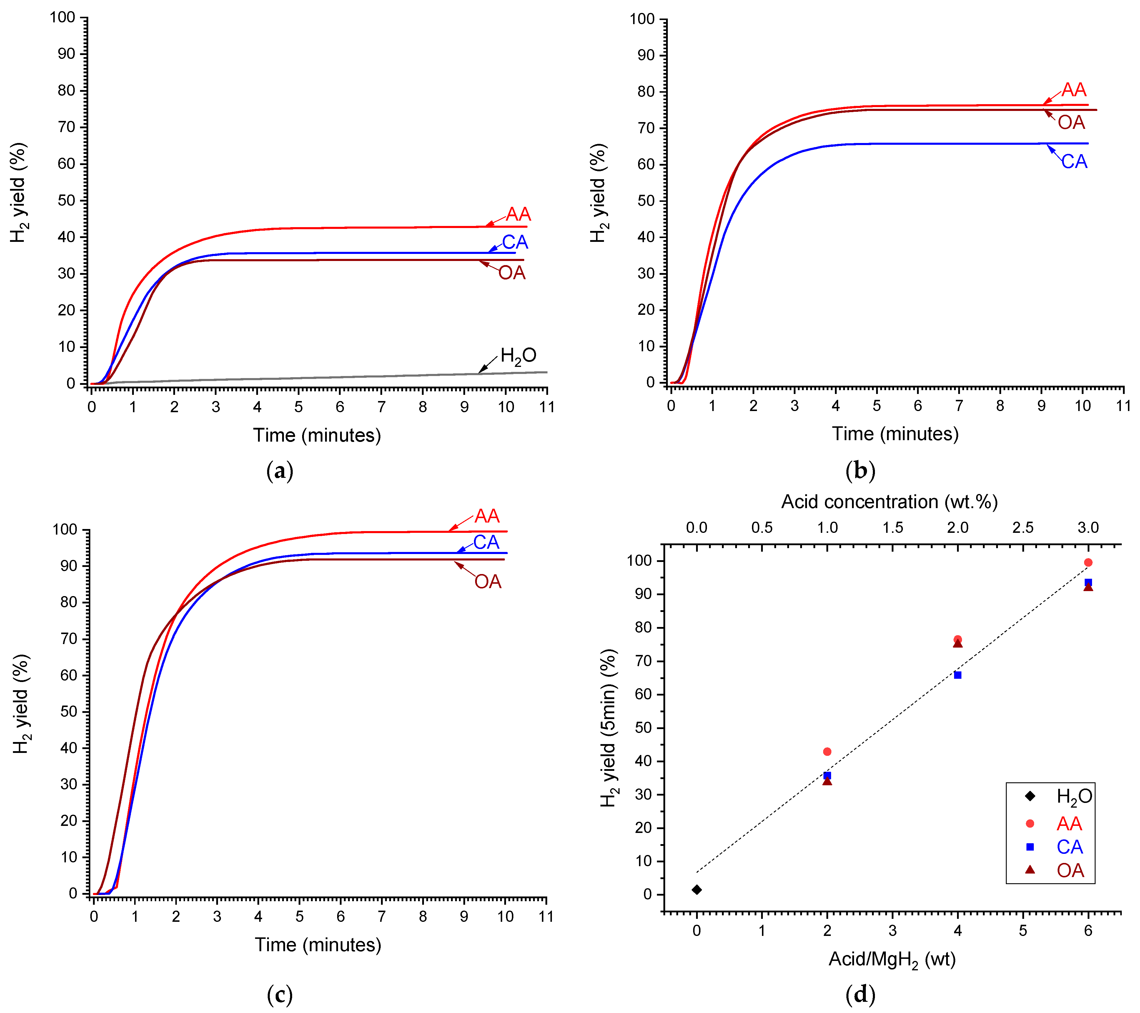
Table 3 summarises results of the hydrolysis experiments carried out at T = 20 °C in 0–3 wt.% aqueous solutions of different organic acids using as-delivered commercial MgH2. The corresponding integral curves of hydrogen generation during hydrolysis (hydrogen yield versus time) are shown in Figure 4a–c.

Table 3.
Summary of experimental results on hydrolysis of commercial MgH2 at T = 20 °C.
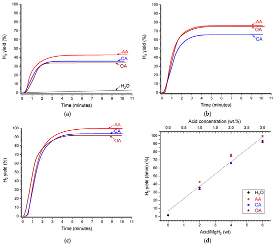
Figure 4.
Time dependencies of the yield of H2 generated by hydrolysis of MgH2 in deionised water (H2O) and aqueous solutions of acetic (AA), citric (CA), and oxalic (OA) acids at the concentrations of 1 (a), 2 (b), and 3 wt.% (c). (d)—Dependencies of H2 yield after 5 min from reaction start on the acid/MgH2 weight ratio (corresponds to the concentration shown on top X-axis); the dashed line shows the linear fit of the concatenated data.
It can be seen in Figure 4a that H2 yield during MgH2 hydrolysis in deionised water (curve labelled as “H2O”) is very low, amounting to 1.5 and 3% after 5 and 10 min, respectively, from the reaction start. The H2 yield significantly increases when introducing organic acids (“AA”, “CA”, and “OA”), even if their concentration is as low as 1 wt.% (Figure 4a). The increase in acid concentration to 2 wt.% (Figure 4b) and further to 3 wt.% (Figure 4c) results in the significant increase in the maximum H2 yield which exceeds 60 and 90%, respectively. The effects of different organic acids on the maximum H2 yield are rather close, with slightly higher yield for the acetic acid. The maximum H2 yield increases approximately linearly with the increase in the acid concentration (in wt.%), or acid/MgH2 weight ratio, approaching 100% when the concentration is equal to or above 3 wt.%, or the weight ratio acid/MgH2 ≥ 6 (Figure 4d).
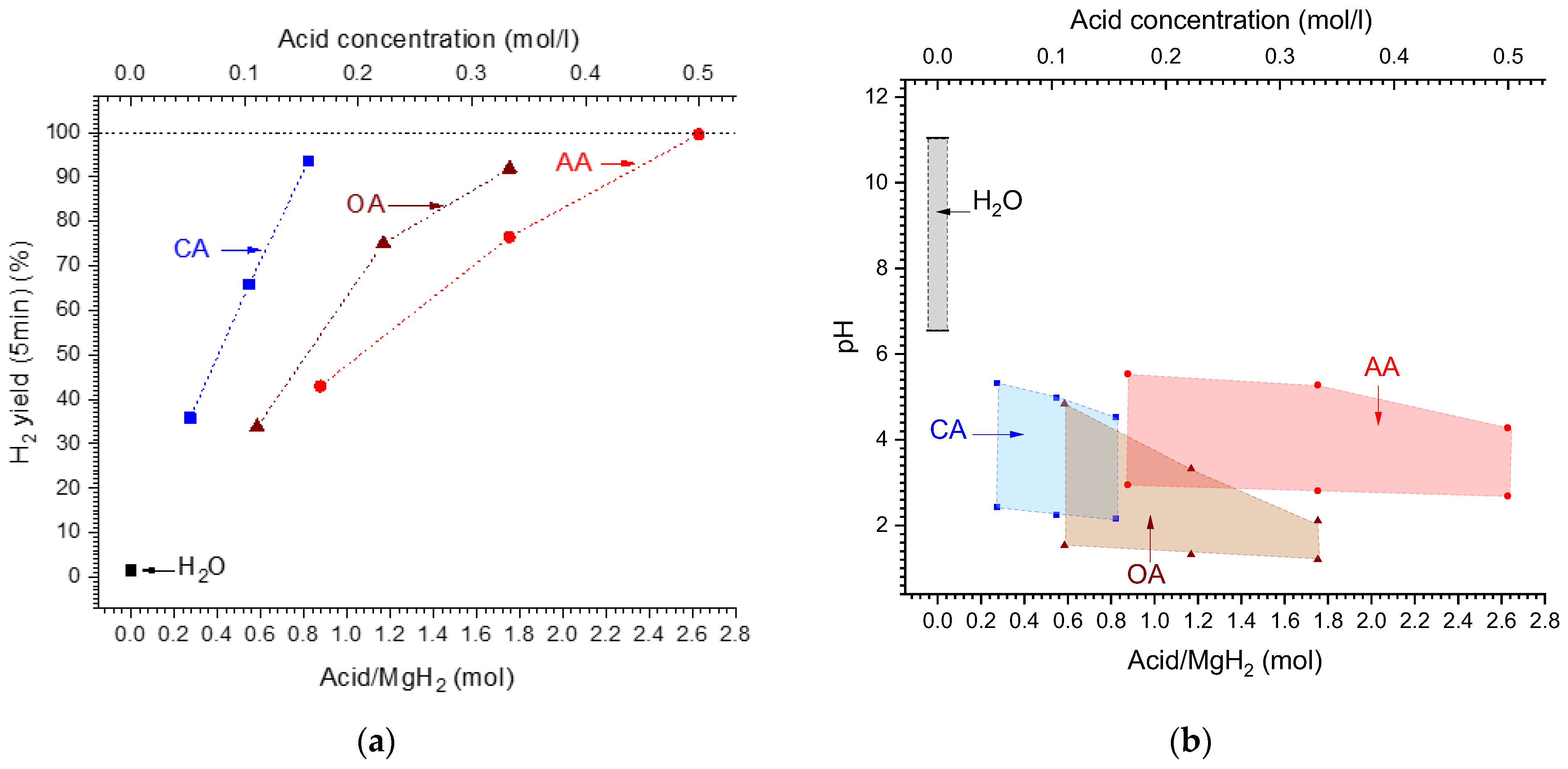
When considering acid/MgH2 molar ratio (or acid molar concentration) (Figure 5a), the corresponding dependencies become different when the H2 yield increases slower for the acids which have lower molecular weight (Table 2). For the latter (“OA” and “AA”), the increase in the H2 yield with the increase in the molar ratio/acid concentration becomes non-linear, slowing when the molar ratio/concentration increases. The 100% hydrogen yield can be achieved at the acid/MgH2 molar ratio of 0.9, 2.0, and 2.7 for the citric, oxalic, and acetic acids, respectively.
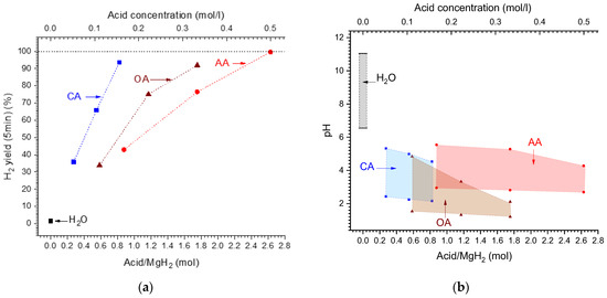
Figure 5.
(a)—Dependencies of H2 yield after 5 min from reaction start on the acid/MgH2 molar ratio (corresponds to the concentration shown on top X-axis). (b)—Changes of the pH of the solution during hydrolysis reaction (bottom lines—initial and top lines—final) depending on the starting acid/MgH2 molar ratio (corresponding to the concentration shown on top X-axis).
As can be seen from Table 3 and Figure 5b, the hydrolysis of MgH2 is accompanied by the increase in pH of the reaction solution. The increase is much more pronounced (by 4.5 pH units) when the reaction starts in pure water/“H2O”, thus changing the medium from approximately neutral (pH = 6.55) to alkaline (pH = 11.04).
Quickly slowing the hydrolysis Reaction 2 in pure water accompanied by the increase in pH of the reaction solution has its origin in the formation of a dense layer of nanocrystalline Mg(OH)2 (weak alkali characterised by very low solubility in water [35]) which pre v ents the diffusion of water molecules to the surface of the MgH2 particles. This is confirmed by our XRD results (Table 1) showing the presence of Mg(OH)2 nanocrystallites (~11 nm) in the deposit after the hydrolysis of MgH2 in deionised water. Conversely, in the deposits after the MgH2 hydrolysis in the acidic solutions, Mg(OH)2 was not detected by XRD, and their SEM images (Figure 1b–d) were very similar to the image of the starting MgH2 (Figure 1a). It allows us to conclude that only unreacted starting material (Mg + MgH2) remains after incomplete hydrolysis of MgH2 in the acidic solutions, without the formation of detectable amounts of magnesium hydroxide.
In the solutions of the studied organic acids (initial pH from 1.21 to 2.95), the changes of the pH are smaller, and the medium remains acidic after hydrolysis (final pH from 2.11 to 5.54). In doing so, hydrolysis reaction slows to a much lesser extent as compared to pure water (see Figure 4a) and is virtually completed at the final pH values of 4.3–4.5 for the acetic and citric acids, and about 2 for the oxalic acid (see Table 3). For the citric and acetic acids, the pH after hydrolysis changes insignificantly with the increase in acid concentration, test ifying to the buffer nature of the solutions “citric acid/magnesium citrate” and “acetic acid/magnesium acetate”. This is not the case when using oxalic acid, due to the low solu bility of magnesium oxalate in water (see Table 2), thus requiring more acidic medium (pH~2) to achieve completion of the hydrolysis. Nevertheless, at the concentrations of oxalic acid ≥ 3 wt.%/0.33 M, the hydrogen yield approaches 100% (Figure 4c).
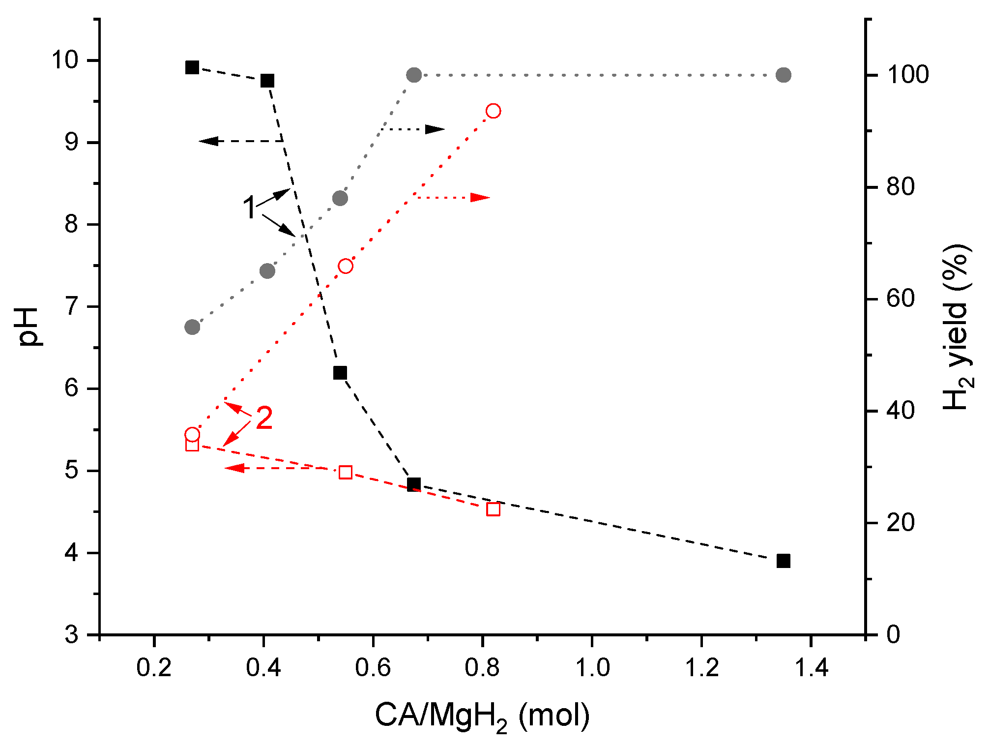
Figure 6 compares the data on pH of the reaction solution after hydrolysis and H2 yield depending on molar ratio “citric acid (CA)/MgH2” reported in [23] (1) and collected during this study (2). While at the high (≥0.7) CA/MgH2 ratio, a good correspondence is observed; this is not the case when the ratio becomes lower, and the values of the pH reported in [23] become significantly higher than the values observed in the present study. The reason for this appears to be in significantly different operating conditions. In [23], the acid was introduced as a component of the compacted solid mixture with MgH2, and water was added dropwise that may result in the incomplete dissolution of the citric acid in the reaction solution after incomplete hydrolysis. Conversely, in our case, water was taken in excess and all the acid was present in the reaction solution whereto the powder of MgH2 was added. In doing so, after incomplete hydrolysis, the remaining Mg + MgH2 deposit (see Table 1) was in contact with the solution which might contain the unreacted citric acid. Another reason may be the higher reactivity of MgH2 prepared by the ball milling of Mg in hydrogen [23], as distinct to commercial magnesium hydride used in this study (compare hydrogen yields shown in Figure 6) that resulted in the higher alkalinity of the solution after hydrolysis.
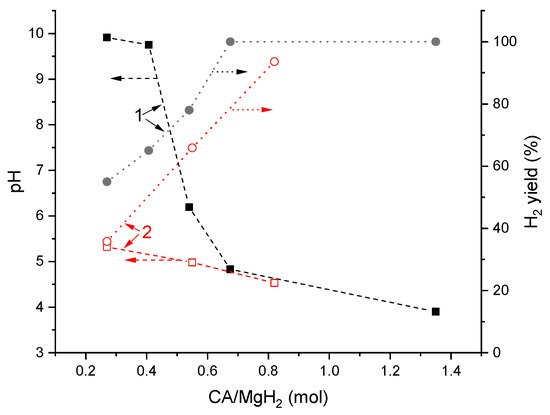
Figure 6.
Dependencies of pH of the reaction solution after hydrolysis and H2 yield on citric acid (CA)/MgH2 molar ratio: 1—reported in ref. [23] and 2—this work.
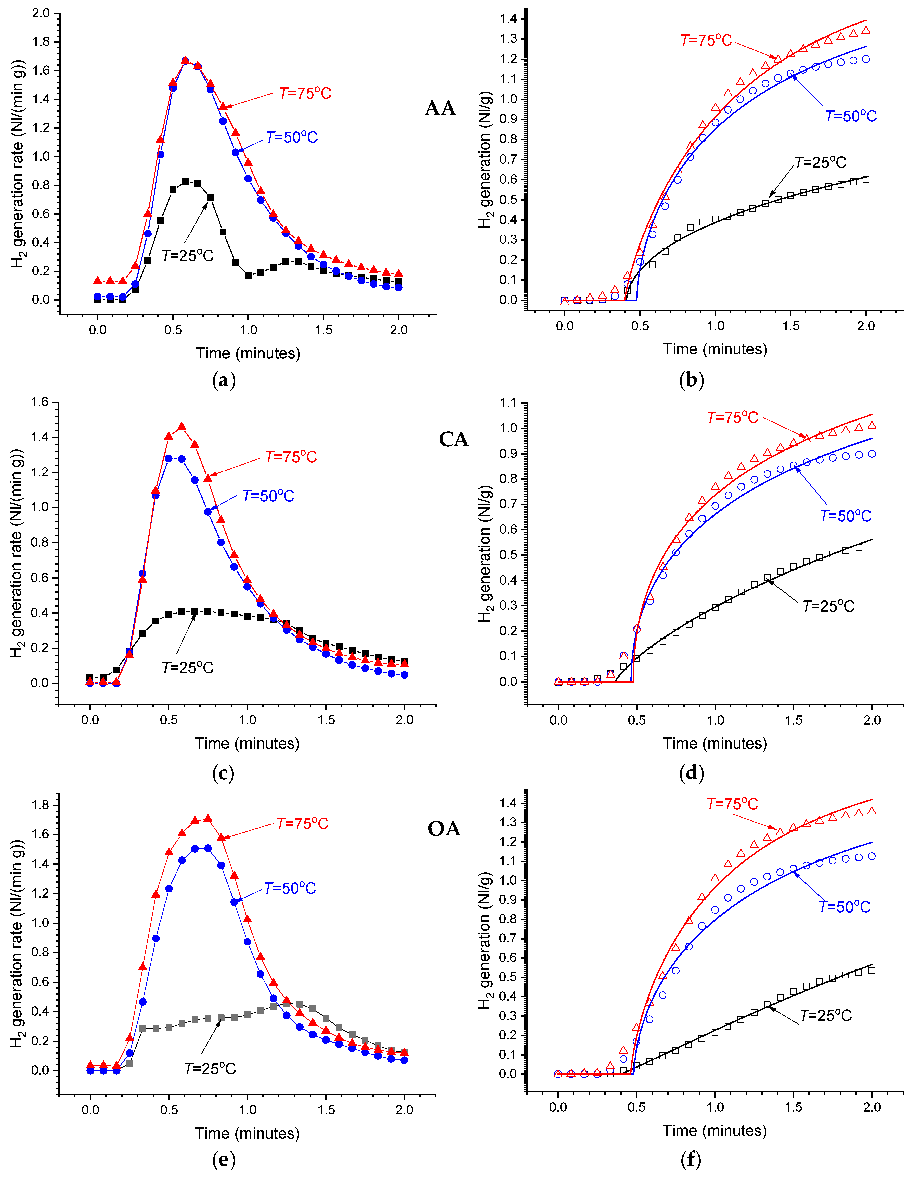
Even at low concentrations of the acids in the reaction solutions (1 wt.%), the hydrolysis of MgH2 is very fast (see Figure 7). The maximum H2 release rate is achieved after ~1 min from the start followed by its decrease. In 3–5 min after the start, the H2 release rate drops below the sensitivity threshold of the used flowmeters. The temperature increase results in the increase in the amount of hydrogen generated during this period, as well as in the increase in the maximum reaction rate which achieves 1.5–1.7 Nl/(min g) at T = 50–70 °C. In the more concentrated solutions (≥2 wt.%), the measured time dependencies of H2 generation rate become very similar to those observed for the 1 wt.% solutions at T = 50–75 °C, exhibiting almost the same maximum reaction rates independently of the temperature. This can be explained by the heating of the reaction solution at the beginning of very fast and highly exothermic hydrolysis Reaction 2, thus introducing its uncontrollable acceleration. We note that direct temperature measurements of the reaction solutions (≥2 wt.%) showed its increase from 25 (thermostat setpoint) to 35–45 °C in the first 1–2 min of performing the process, followed by a gradual decrease to the setpoint.
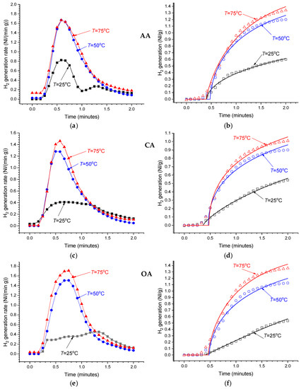
Figure 7.
As-measured hydrogen generation rates (a,c,e) and the integrated H2 generation curves (b,d,f) for the hydrolysis of commercial MgH2 in 1 wt.% solutions of acetic (AA), citric (CA), and oxalic (OA) acids at different temperatures.
Modelling of the integrated experimental data on hydrogen evolution rates (Equation (3); see Figure 7b,d,f) using the modified Avrami–Erofeev equation (Equation (4)) allowed us to achieve quite good fits, with Pearson correlation coefficients, R2, between 0.99 and 0.995. Analysis of temperature dependencies of the fitted parameters ti, t0, and n (see Table 4) allows to summarise our observations as follows:

Table 4.
Fitted parameters (Equation (4)) of the integrated H2 generation curves (Figure 7b,d,f).
- In all studied cases, the fitted values of incubation period, ti = 0.4–0.5 min, change insignificantly and appear to be related to the specifics of the applied experimental procedure;
- The fitted Avrami exponents vary within the range n = 0.5–1.1, close to the values reported by Huang et al. [39] for the hydrolysis of MgH2 in 0.5–4.5 wt.% aqueous solutions of NH4Cl. According to ref. [52], the values of n close to 0.5 correspond to diffusion as the rate-limiting step while the higher values of n testify about possible contribution of the nucleation and growth mechanism;
- The hydrolysis activation energies calculated from the temperature dependencies of the fitted values of rate constants, K = 1/t0, vary between 20 and 37 kJ/mol. We note that the presented values are just rough estimations due to rather poor fitting of the data with Equation (5) (see Figure S1 in Supplementary Information). In our opinion, this is caused by the under-estimation of the measured hydrogen evolution rates above 1.5 Nl/(min g) that takes place at the higher temperature (75 °C) and/or the higher concentrations of the organic acids.
Nevertheless, the estimated values of the activation energy of hydrogen generation by hydrolysis of MgH2 in 1 wt.% solutions of organic acids were found to be significantly lower than the reported value for MgH2 hydrolysis in de-ionized water (~58 kJ/mol) and close to the value of ~30 kJ/mol determined for the hydrolysis in 4.5 wt.% solution of NH4Cl [39]. The activation energy for 1 wt.% solution of citric acid estimated with a reasonable accuracy (20 ± 4 kJ/mol) was found to be significantly lower.
2.3. Application-Related Findings
According to the results presented above, the most efficient and economical way to implement the hydrolysis technology for the generation of hydrogen is in the use of MgH2, along with solutions of organic acids, particularly, citric acid. The selection is based on the following features:
- The possibility of effectively controlling the process by controlling the acid/MgH2 ratio in the reaction solution, as well as its temperature;
- The availability and low cost of magnesium and citric acid;
- The high solubility of both citric acid and magnesium citrate in water;
- The formation of moderately acidic buffer solutions “citric acid—magnesium citrate” characterised by pH between 3 and 5 in a wide range of concentrations. The range of the pH is sufficient to suppress the deposition of Mg(OH)2 passivation layer on the surface of the MgH2 particles and, thus, to provide a high yield of hydrogen generation. At the same time, it creates less corrosive medium than in the case of mineral acids, or oxalic acid studied in this work;
- As distinct from acetic acid, citric acid is not volatile which significantly reduces the contamination of the released H2 containing only easily removed impurities of water vapours and mist of the reaction solution;
- The lower rates in combination with lower activation energy of H2 generation by hydrolysis of MgH2 in the solution of citric acid allow more efficient process control due to less pronounced self-heating of the reaction solution when highly exothermic hydrolysis reaction takes place.
3. Generation of Compressed Hydrogen by Hydrolysis of Mg or MgH2 in Citric Acid Solution
As mentioned in the Introduction, the development of efficient systems for hydrogen generation by hydrolysis requires engineering solutions aimed at the increase in the reaction yield and rate, and, at the same time, the possibility of controlling the process. Mostly, these solutions are focused on the controlled supply of the reactants into the hydrolysis reactor, as well as controlling the pH of the reaction solution.
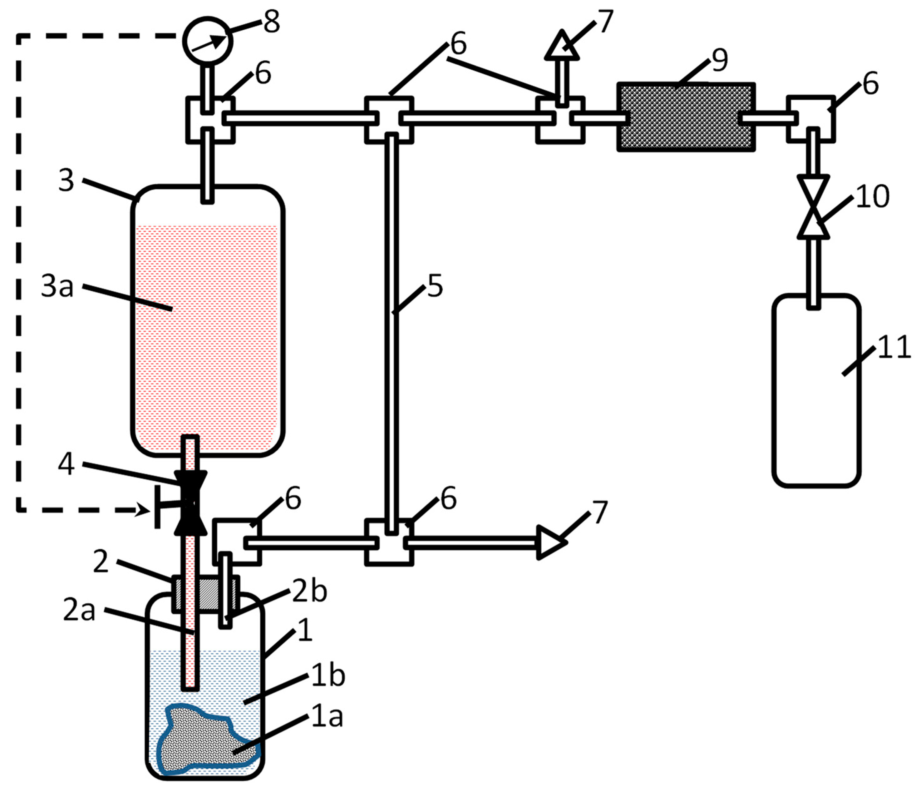
A simplified schematics of the apparatus for the generation of pressurised hydrogen by the hydrolysis of Mg or MgH2 in acidic solutions developed by the Russian co-authors of this article [44] is shown in Figure 8.
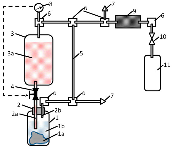
Figure 8.
Schematics of the apparatus for the generation of compressed hydrogen by hydrolysis of Mg or MgH2 in acidic solutions. 1—reactor, 1a—hydrogen-generating material, 1b—water; 2—dosing plug, 2a—acid-solution supply pipeline, 2b—hydrogen-outlet pipeline; 3—reservoir, 3a—acid solution; 4—acid-solution supply valve; 5—gas-outlet pipeline; 6—gas manifolds; 7—overpressure safety valves; 8—pressure sensor; 9—hydrogen purifier; 10—shut-off gas valve; and 11—hydrogen cylinder/receptacle.
Hydrogen generation takes place in reactor (1). Before starting the process, a solid hydrogen-generating material (1a; Mg, MgH2, or a composite on their basis) is loaded in the reactor in the form of powder, granules, or foil, followed by the filling of the reactor with water (1b). Since the hydrolysis of the hydrogen-generating material in pure water is very slow (see curve “H2O” in Figure 4a as an example for MgH2), there is no significant hydrogen release at this stage. Then, the orifice of the reactor is closed with a dosing plug (2) equipped with pipelines for acid supply (2a) and hydrogen outlet (2b); then, the opposite ends of the pipelines are connected to the acid supply and gas distributing systems, respectively. The former comprises the reservoir (3) filled with the acid solution (3a) supplied via valve (4). The gas distributing system includes a pipeline (5) which connects the gas outlet of the reactor (1) with the opposite (upper) end of the sealed reservoir (3), thus maintaining equal pressures in the gas spaces of reactor (1) and reservoir (3). Additionally, this includes gas manifolds (6), overpressure safety valves (7), pressure sensor (8), and hydrogen purifier (9) which removes mist and water vapour from hydrogen released in the reactor (1) when the acid solution is supplied thereto via the valve (4). The pressurised hydrogen fills the gas cylinder (11) connected to the system by a shut-off valve (10).
The process of hydrogen generation can easily be controlled by the valve (4) which supplies the acid solution (3a) which further interacts with the hydrogen-generating material (1a), thus releasing hydrogen at the pressure equal to the pressure in the gas space of the reservoir (3). Control can be automated by introducing feedback between the pressure sensor (8) and an actuator of the valve (4), as shown by the dashed arrow in Figure 8.
The tests of the apparatus described above were carried out using powders of magnesium (m = 80–150 g) or magnesium hydride (m = 40 g) and 1.6 L of 4 M solution of citric acid in the reservoir (3), so the maximum molar ratio “acid/Mg” or “acid/MgH2” varied between 1.05 and 3.8. In all cases, the maximum amount of the generated H2 was 0.79 Nl/g for Mg (85.7% yield of Reaction 1) and 1.42 Nl/g for MgH2 (83.3% yield of Reaction 2). Depending on the amount of the hydrogen-generating material, the maximum H2 pressure was achieved when filling the gas cylinder, 1 L in the internal volume, varied between 50 and 100 bar. The hydrogen generation time controlled by the supply of the acid solution was between 0.5 and 5 h; in doing so at the same conditions hydrogen release when using MgH2 was 2.5 times faster than for Mg. We note that further shortening of the hydrogen-generation time, first of all, depends on providing efficient heat removal from the hydrolysis reactor because during the tests the supply of citric acid solution into the reactor was limited to avoid uncontrolled self-heating of the reaction solution. The corresponding upgrade of the hydrogen generation apparatus, as well as optimising the procedure of the generation of pressurised hydrogen, are on-going. The results will be published in due course.
4. Materials and Methods
4.1. Materials and Their Characterisation
99.8% purity commercial MgH2 powder (Alfa Aesar) with average particle size of 50 μm was used for the hydrolysis experiments. The morphology of the starting MgH2 and the deposits after its hydrolysis was studied using a Zeiss Auriga scanning electron microscope (SEM). XRD analysis of the samples was performed using a Bruker AXS D8 Advance diffractometer with Cu-Kα radiation (λ1 = 1.5406 Å, λ2 = 1.5444 Å, and λ2/λ1 = 0.5), in the range of Bragg angles 2θ = 10–90°. Rietveld full profile analysis of the patterns was performed using the General Structure Analysis System (GSAS) software.
Reference data for the phases identified during the XRD refinements are summarised in Table 5.

Table 5.
Reference data for the phases identified during Rietveld refinement of the XRD patterns.
4.2. Hydrolysis Experiments and Data Processing
The hydrolysis experiments were performed using deionised water and aqueous solutions of organic acids: acetic (AA; 99.8% purity), citric (CA; 99.5%), and oxalic (OA; 99.5%). The summary of the main properties of the acids and their magnesium salts, along with concentrations of the used reaction solutions, is presented in Table 2.
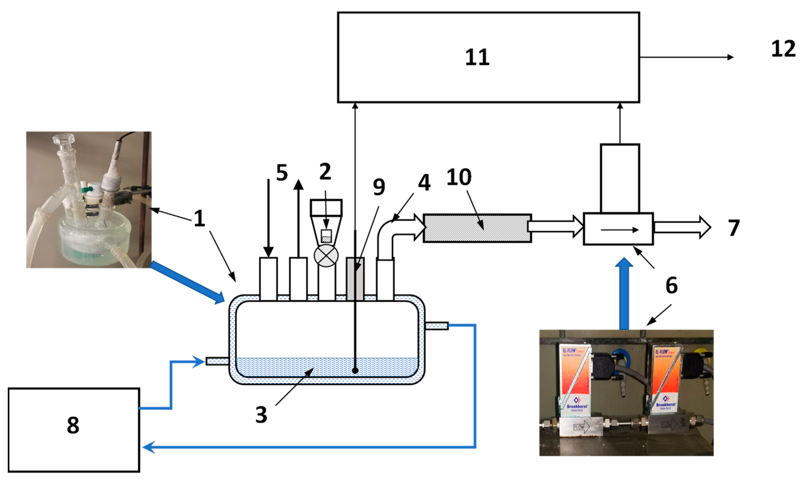
The measurements of hydrogen evolution during hydrolysis were carried out using in-house-built volumetric setup schematically shown in Figure 9. The experiments included studies of hydrogen-generation rates during hydrolysis of commercial MgH2 in the dilute (0–3 wt.%) solutions of the acetic, citric, and oxalic acids. 40 mL of the reaction solution (3) was placed inside a five-neck borosilicate flat-bottomed jacketed reactor flask (1) kept at a constant temperature (between 20 and 75 °C) with the help of a thermostat (8) whose circulation loop was connected to the jacket of the flask (1). The temperature of the reaction solution was measured using a K-type thermocouple (9) inserted inside the flask through one of its necks. Once the desired temperature was reached and the reactor with the solution was flushed with hydrogen (5), the sample (2; m = 200 mg) was added to the reactor flask through its centre neck. The hydrogen generated in the reactor (1) during the hydrolysis reaction flowed through the outlet pipe (4), moisture trap (10; a tube filled with CaCl2 granules), thermal mass flowmeters (6; Bronkhorst, EL-FLOW series) and then released into the atmosphere (7).
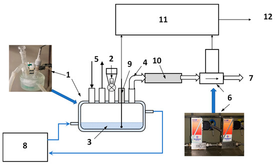
Figure 9.
Schematics of laboratory setup for studies of hydrogen generation by hydrolysis of MgH2. 1—reactor flask; 2—sample; 3—reaction solution; 4—H2 outlet pipe; 5—hydrogen flush; 6—mass flow meters; 7—H2 release; 8—thermostat; 9—temperature sensor; 10—moisture trap; and 11—data acquisition unit; 12—PC.
Correct measurements of the flow of the hydrogen released during the hydrolysis reaction pose a certain problem due to high H2 flow at the beginning of the reaction and its subsequent quick drop afterwards. On the other hand, the readings of thermal mass flowmeters at gas flows below ~10% of their full scale become inaccurate which may introduce high systematic error at the end of the hydrolysis process. We mitigated this problem by using two individually calibrated mass flowmeters (1 and 10 Nl/min full scale) connected in series that allowed us to measure the flow rate of the released hydrogen in the range 0.1–10 Nl/min. The data logging was interrupted after the readings of the flow measurement system dropped below the lower limit of the “trustable” range specified above (as a rule, after 8–11 min from starting the process).
The thermocouple (9) and outputs of the flowmeters (6) were connected to a datalogger (11) based on NI DAQ modules. The data acquisition (5 s time resolution) was performed using PC (12) and in-house-developed software operating in LabView environment. pH of the solutions before and after hydrolysis were measured by a Metrohm 827 pH meter. Standard solutions with pH equal to 4, 7, and 9 were used for the calibration.
The collected data on the rates of hydrogen generation, v(t), were further processed as follows.
The dependencies v(t) were integrated to calculate time dependencies of H2 generation, V(t), as:
The integral kinetic curves (Equation (3)) in the range t = 0–2 min taken for 1 wt.% solutions of the organic acids at different temperatures (25, 50 and 75 °C) were fitted by a modified Avrami–Erofeev equation:
where Vmax is the maximum hydrogen generation corresponding to 100% yield of the hydrolysis Reaction 2 and equal to 1.703 Nl per 1 g of MgH2, n is Avrami exponent indirectly related to the reaction mechanism, ti is the incubation period, and t0 is the characteristic reaction time or reciprocal rate constant.
Since the rates of hydrogen generation at the acid concentrations above 1 wt.% were very close for the different temperatures (see Section 2.2 above), kinetic analysis was not applied for these data.
The apparent activation energies of the process were estimated from the slopes of linear dependencies of the logarithms of reaction rate constants, K = 1/t0, on the reciprocal absolute temperature, 1/T, fitted by the Arrhenius equation:
where K [min–1] is the rate constant, EA [J/mol] is the activation energy, T [K] is temperature, A is the free term (intercept), and R = 8.31432 J/(mol K) is the universal gas constant.
5. Conclusions
It was demonstrated that the addition of the studied organic acids significantly increases the yield and rate of hydrogen generation via hydrolysis of magnesium hydride, most probably by preventing the formation of a Mg(OH)2 passivation layer, even if the acid concentration in the solution was as low as 1 wt.%. The hydrogen yield achieved after 3–5 min from starting the hydrolysis reaction in the acidic solution increases with the increase in the acid/MgH2 ratio and approaches 100% when the molar ratio acid/MgH2 exceeds 0.9, 2.0, and 2.7 for the citric, oxalic, and acetic acids, respectively.
The course of MgH2 hydrolysis strongly depends on the pH of the reaction solution: the 100% yield can be achieved at pH below ~4.5 for the acetic and citric acids and below ~2 for the oxalic acid. For the citric and acetic acids, the pH after hydrolysis changes insignificantly with the increase in acid concentration that testifies to the buffer nature of the solutions “citric acid/magnesium citrate” and “acetic acid/magnesium acetate”.
The most efficient and economical way to implement technology of the hydrolysis of MgH2 for the generation of hydrogen is the use of solutions of citric acid due to (i) its availability and low cost; (ii) the possibility of effectively controlling the process by controlling the temperature, along with acid/MgH2 ratio in the reaction solution; (iii) the high solubility of both citric acid and magnesium citrate in water; (iv) the low volatility; and (v) the formation of moderately acidic buffer solutions “citric acid—magnesium citrate” characterised by a pH range sufficient to suppress the deposition of Mg(OH)2 passivation layer and, at the same time, not creating a corrosive environment.
Based on the obtained results, a prototype generator of pressurised hydrogen by the hydrolysis of Mg or MgH2 in the solution of citric acid has been developed and tested. The main feature of the generator is the possibility of reaction control by the controlled supply of the acidic solution to the hydrolysis reactor. The developed hydrogen generator demonstrated the possibility of controlled hydrogen release at the pressure of up to 100 bar with H2 yield of 0.79 and 1.42 NI/g using magnesium and magnesium hydride, respectively, as a hydrogen-generating material. At the same operating conditions, hydrogen release when using MgH2 was 2.5 times faster than for Mg.
6. Patents
The following patented solution contributed to the results reported in this work:
- Compressed Hydrogen Producing Method and Device for Implementation Thereof, by A.A. Arbuzov, Y.Y. Shimkus, S.A. Mozhzhukhin, V.B. Son, and B.P. Tarasov. RU 2735285 C1 (2020).
Supplementary Materials
The following supporting information can be downloaded at: https://www.mdpi.com/article/10.3390/inorganics11080319/s1. Figure S1: Arrhenius plots for hydrogen generation by hydrolysis of MgH2 in 1 wt.% aqueous solutions of acetic (AA), citric (CA), and oxalic (OA) acids.
Author Contributions
Conceptualization, M.V.L. and B.P.T.; methodology, M.W.D. and A.A.A.; validation, T.K.S., A.A.A. and S.A.M.; formal analysis, M.V.L.; investigation, M.W.D., T.K.S., A.A.A. and S.A.M.; resources, M.V.L. and B.P.T.; data curation, Y.Z. and R.T.; writing—original draft preparation, T.K.S., M.W.D. and A.A.A.; writing—review and editing, M.V.L.; visualization, Y.Z. and R.T.; supervision, M.V.L. and B.P.T.; project administration, M.V.L. and B.P.T.; funding acquisition, M.V.L., M.W.D. and B.P.T. All authors have read and agreed to the published version of the manuscript.
Funding
The work of the South African team (Section 1, Section 2 and Section 4, contribution into Section 5) was funded by the Department of Science and Innovation (DSI) of South Africa within “Hydrogen South Africa” (HySA) Research, Development, and Innovation Program (project KP6-S01). The South African co-authors also acknowledge financial support from the South African National Research Foundation (NRF) (grant numbers 116278 (M.W.D.) and 132454 (M.L.)). The studies performed at the Federal Research Centre of Problems of Chemical Physics and Medicinal Chemistry of the Russian Academy of Sciences (Section 2.3 and Section 3, contribution into Section 1, Section 2.2 and Section 5) were supported by the Ministry of Science and Higher Education of the Russian Federation (grant number 075-15-2022-1126).
Data Availability Statement
The data presented in this study are available on request from the corresponding author.
Acknowledgments
This work was performed using the equipment of FRC PCP & MC RAS, https://www.icp.ac.ru/en/ (accessed on 20 July 2023) and HySA Systems hosted by the University of the Western Cape, http://hysasystems.com/ (accessed on 20 July 2023).
Conflicts of Interest
The authors declare no conflict of interest.
References
- Dell, R.M.; Rand, D.A.G. Energy Storage—A Key Technology for Global Energy Sustainability. J. Power Sources 2001, 100, 2–17. [Google Scholar] [CrossRef]
- Barbir, F. PEM Fuel Cells: Theory and Practice, 2nd ed.; Academic Press/Elsevier: Amsterdam, The Netherlands, 2013. [Google Scholar]
- Faye, O.; Szpunar, J.; Eduok, U. A Critical Review on the Current Technologies for the Generation, Storage, and Transportation of Hydrogen. Int. J. Hydrogen Energy 2022, 47, 13771–13802. [Google Scholar] [CrossRef]
- Chakraborty, S.; Dash, S.K.; Elavarasan, R.M.; Kaur, A.; Elangovan, D.; Meraj, S.T.; Kasinathan, P.; Said, Z. Hydrogen Energy as Future of Sustainable Mobility. Front. Energy Res. 2022, 10, 893475. [Google Scholar] [CrossRef]
- Hassan, I.A.; Ramadan, H.S.; Saleh, M.A.; Hissel, D. Hydrogen Storage Technologies for Stationary and Mobile Applications: Review, Analysis and Perspectives. Renew. Sustain. Energy Rev. 2021, 149, 111311. [Google Scholar] [CrossRef]
- Gil-San-Millan, R.; Grau-Atienza, A.; Johnson, D.T.; Rico-Francés, S.; Serrano, E.; Linares, N.; García-Martínez, J. Improving Hydrogen Production from the Hydrolysis of Ammonia Borane by Using Multifunctional Catalysts. Int. J. Hydrogen Energy 2018, 43, 17100–17111. [Google Scholar] [CrossRef]
- Akbayrak, S.; Çakmak, G.; Öztürk, T.; Özkar, S. Rhodium(0), Ruthenium(0) and Palladium(0) Nanoparticles Supported on Carbon-Coated Iron: Magnetically Isolable and Reusable Catalysts for Hydrolytic Dehydrogenation of Ammonia Borane. Int. J. Hydrogen Energy 2021, 46, 13548–13560. [Google Scholar] [CrossRef]
- Abdelhamid, H.N. A Review on Hydrogen Generation from the Hydrolysis of Sodium Borohydride. Int. J. Hydrogen Energy 2021, 46, 726–765. [Google Scholar] [CrossRef]
- Tarasov, B.P. Metal-Hydride Accumulators and Generators of Hydrogen for Feeding Fuel Cells. Int. J. Hydrogen Energy 2011, 36, 1196–1199. [Google Scholar] [CrossRef]
- Zhu, Y.; Li, J.; Yang, L.; Huang, Z.; Yang, X.-S.; Zhou, Q.; Tang, R.; Shen, S.; Ouyang, L. Closed Loops for Hydrogen Storage: Hydrolysis and Regeneration of Metal Borohydrides. J. Power Sources 2023, 563, 232833. [Google Scholar] [CrossRef]
- Yartys, V.; Zavaliy, I.; Berezovets, V.; Pirskyy, Y.; Manilevich, F.; Kytsya, A.; Verbovytskyy, Y.; Dubov, Y.; Kutsyi, A. Hydrogen Generator Integrated with Fuel Cell for Portable Energy Supply. J. Phys. Energy 2023, 5, 014014. [Google Scholar] [CrossRef]
- Liu, H.; Yang, F.; Yang, B.; Zhang, Q.; Chai, Y.; Wang, N. Rapid Hydrogen Generation through Aluminum-Water Reaction in Alkali Solution. Catal. Today 2018, 318, 52–58. [Google Scholar] [CrossRef]
- Xu, H.; Wang, H.; Zhang, Z.; Tu, H.; Xiong, J.; Xiang, X.; Wei, C.; Mishra, Y.K. High Efficiency Al-Based Multicomponent Composites for Low-Temperature Hydrogen Production and Its Hydrolysis Mechanism. Int. J. Hydrogen Energy 2023, 48, 26260–26275. [Google Scholar] [CrossRef]
- Legrée, M.; Bobet, J.-L.; Mauvy, F.; Sabatier, J. Modeling Hydrolysis Kinetics of Dual Phase α-Mg/LPSO Alloys. Int. J. Hydrogen Energy 2022, 47, 23084–23093. [Google Scholar] [CrossRef]
- Liu, Z.; Zhong, J.; Leng, H.; Xia, G.; Yu, X. Hydrolysis of Mg-Based Alloys and Their Hydrides for Efficient Hydrogen Generation. Int. J. Hydrogen Energy 2021, 46, 18988–19000. [Google Scholar] [CrossRef]
- al Bacha, S.; Pighin, S.A.; Urretavizcaya, G.; Zakhour, M.; Castro, F.J.; Nakhl, M.; Bobet, J.L. Hydrogen Generation from Ball Milled Mg Alloy Waste by Hydrolysis Reaction. J. Power Sources 2020, 479, 228711. [Google Scholar] [CrossRef]
- Kushch, S.D.; Kuyunko, N.S.; Nazarov, R.S.; Tarasov, B.P. Hydrogen-Generating Compositions Based on Magnesium. Int. J. Hydrogen Energy 2011, 36, 1321–1325. [Google Scholar] [CrossRef]
- Sevastyanova, L.G.; Genchel, V.K.; Klyamkin, S.N.; Larionova, P.A.; Bulychev, B.M. Hydrogen Generation by Oxidation of “Mechanical Alloys” of Magnesium with Iron and Copper in Aqueous Salt Solutions. Int. J. Hydrogen Energy 2017, 42, 16961–16967. [Google Scholar] [CrossRef]
- Kojima, Y.; Suzuki, K.-I.; Kawai, Y. Hydrogen Generation by Hydrolysis Reaction of Magnesium Hydride. J. Mater. Sci. 2004, 39, 2227–2229. [Google Scholar] [CrossRef]
- Tegel, M.; Schöne, S.; Kieback, B.; Röntzsch, L. An Efficient Hydrolysis of MgH2-Based Materials. Int. J. Hydrogen Energy 2017, 42, 2167–2176. [Google Scholar] [CrossRef]
- Verbovytskyy, Y.V.; Berezovets, V.V.; Kytsya, A.R.; Zavaliy, I.Y.; Yartys, V.A. Hydrogen Generation by the Hydrolysis of MgH2. Mater. Sci. 2020, 56, 1–14. [Google Scholar] [CrossRef]
- Zhu, Y.; Wang, Y.; Zeng, L.; Wu, D.; Lu, C.; Yang, X.-S.; Zhou, Q.; Tang, R.; Xiao, F. Effect of Metaborate Additive Modification on Hydrolysis Performance of MgH 2. ACS Appl. Energy Mater. 2023, 6, 461–470. [Google Scholar] [CrossRef]
- Berezovets, V.V.; Kytsya, A.R.; Zasadnyy, T.M.; Zavaliy, I.Y.; Yartys, V.A. Generation of Hydrogen by the Hydrolysis of Mixtures of Magnesium Hydride with Citric Acid. Mater. Sci. 2022, 58, 350–356. [Google Scholar] [CrossRef]
- Ouyang, L.; Liu, M.; Chen, K.; Liu, J.; Wang, H.; Zhu, M.; Yartys, V. Recent Progress on Hydrogen Generation from the Hydrolysis of Light Metals and Hydrides. J. Alloys Compd. 2022, 910, 164831. [Google Scholar] [CrossRef]
- Hiraki, T.; Okinaka, N.; Uesugi, H.; Akiyama, T. Direct Production of Pressurized Hydrogen from Waste Aluminum without Gas Compressor. In Materials Issues in a Hydrogen Economy; World Scientific: Singapore, 2009; pp. 54–61. [Google Scholar]
- Yartys, V.A.; Lototskyy, M.V.; Akiba, E.; Albert, R.; Antonov, V.E.; Ares, J.R.; Baricco, M.; Bourgeois, N.; Buckley, C.E.; Bellosta von Colbe, J.M.; et al. Magnesium Based Materials for Hydrogen Based Energy Storage: Past, Present and Future. Int. J. Hydrogen Energy 2019, 44, 7809–7859. [Google Scholar] [CrossRef]
- Grosjean, M.H.; Zidoune, M.; Roué, L.; Huot, J.Y. Hydrogen Production via Hydrolysis Reaction from Ball-Milled Mg-Based Materials. Int. J. Hydrogen Energy 2006, 31, 109–119. [Google Scholar] [CrossRef]
- Ouyang, L.; Ma, M.; Huang, M.; Duan, R.; Wang, H.; Sun, L.; Zhu, M. Enhanced Hydrogen Generation Properties of MgH2-Based Hydrides by Breaking the Magnesium Hydroxide Passivation Layer. Energies 2015, 8, 4237–4252. [Google Scholar] [CrossRef]
- Pighin, S.A.; Urretavizcaya, G.; Bobet, J.L.; Castro, F.J. Nanostructured Mg for Hydrogen Production by Hydrolysis Obtained by MgH2 Milling and Dehydriding. J. Alloys Compd. 2020, 827, 154000. [Google Scholar] [CrossRef]
- Zhao, Y.; Li, T.; Huang, H.; Xu, T.; Liu, B.; Zhang, B.; Yuan, J.; Wu, Y. A Highly Efficient Hydrolysis of MgH2 Catalyzed by NiCo@C Bimetallic Synergistic Effect. J. Mater. Sci. Technol. 2023, 137, 176–183. [Google Scholar] [CrossRef]
- Hiroi, S.; Hosokai, S.; Akiyama, T. Ultrasonic Irradiation on Hydrolysis of Magnesium Hydride to Enhance Hydrogen Generation. Int. J. Hydrogen Energy 2011, 36, 1442–1447. [Google Scholar] [CrossRef]
- Grosjean, M.H.; Zidoune, M.; Huot, J.Y.; Roué, L. Hydrogen Generation via Alcoholysis Reaction Using Ball-Milled Mg-Based Materials. Int. J. Hydrogen Energy 2006, 31, 1159–1163. [Google Scholar] [CrossRef]
- Zhao, Z.; Zhu, Y.; Li, L. Efficient Catalysis by MgCl2 in Hydrogen Generation via Hydrolysis of Mg-Based Hydride Prepared by Hydriding Combustion Synthesis. Chem. Commun. 2012, 48, 5509. [Google Scholar] [CrossRef]
- Gan, D.; Liu, Y.; Zhang, J.; Zhang, Y.; Cao, C.; Zhu, Y.; Li, L. Kinetic Performance of Hydrogen Generation Enhanced by AlCl3 via Hydrolysis of MgH2 Prepared by Hydriding Combustion Synthesis. Int. J. Hydrogen Energy 2018, 43, 10232–10239. [Google Scholar] [CrossRef]
- Berezovets, V.; Kytsya, A.; Zavaliy, I.; Yartys, V.A. Kinetics and Mechanism of MgH2 Hydrolysis in MgCl2 Solutions. Int. J. Hydrogen Energy 2021, 46, 40278–40293. [Google Scholar] [CrossRef]
- Sevastyanova, L.G.; Klyamkin, S.N.; Stupnikov, V.A.; Bulychev, B.M. Disposable Hydrogen Generators: Magnesium Hydride Oxidation in Aqueous Salts Solutions. Int. J. Hydrogen Energy 2022, 47, 92–101. [Google Scholar] [CrossRef]
- Makhaev, V.D.; Petrova, L.A.; Tarasov, B.P. Hydrolysis of Magnesium Hydride in the Presence of Ammonium Salts. Russian J. Inorg. Chem. 2008, 53, 858–860. [Google Scholar] [CrossRef]
- Hiraki, T.; Hiroi, S.; Akashi, T.; Okinaka, N.; Akiyama, T. Chemical Equilibrium Analysis for Hydrolysis of Magnesium Hydride to Generate Hydrogen. Int. J. Hydrogen Energy 2012, 37, 12114–12119. [Google Scholar] [CrossRef]
- Huang, M.; Ouyang, L.; Wang, H.; Liu, J.; Zhu, M. Hydrogen Generation by Hydrolysis of MgH2 and Enhanced Kinetics Performance of Ammonium Chloride Introducing. Int. J. Hydrogen Energy 2015, 40, 6145–6150. [Google Scholar] [CrossRef]
- Tegel, M.; Rontzsch, L.; Kieback, B. Composite Material for Hydrolytically Generating Hydrogen, Device for Hydrolytically Generating Hydrogen, Method for Generating Hydrogen, Device for Generating Electric Energy, and Possible Applications. U.S. Patent 10239753 B2, 26 March 2019. [Google Scholar]
- Ryu, W.; Braithwaite, D.; Fabian, T. Chemical Hydride Formulation and System Design for Controlled Generation of Hydrogen. U.S. Patent Application 2011/0020215 A1, 27 January 2011. [Google Scholar]
- Mauvy, F.C.M.; Bobet, J.-L.; Sabatier, J.; Bos, F. Use of a Magnesium-Based Material for Producing Dihydrogen or Electricity. U.S. Patent 10407303 B2, 10 September 2019. [Google Scholar]
- Wankewycz, T.; Crawford, M.M.; Tan, L.Y.; Zhang, X. High Energy Density Fuel Cell Apparatus and System with a Hydride-Based Hydrogen Generator as a Scalable Power Solution Concept. U.S. Patent Application 2022/0131214 A1, 28 April 2022. [Google Scholar]
- Arbuzov, A.A.; Shimkus, Y.Y.; Mozhzhukhin, S.A.; Son, V.B.; Tarasov, B.P. Compressed Hydrogen Producing Method and Device for Implementation Thereof. Russian Patent 2735285 C1, 29 October 2020. [Google Scholar]
- Sgroi, A., Jr.; Stepan, C.R.; Curello, A.J.; Curello, M. Fuels for Hydrogen Generating Cartridges. U.S. Patent 8636961 B2, 28 January 2014. [Google Scholar]
- Li, H.; Fu, Q.; Qin, H.; Chen, X.; Zhang, Q.; Zhang, H.; Wang, S.; Dong, Z.; Wang, M. Geometric Optimization of Hydrolysis Reactors to Enhance MgH2 Hydrolysis Performance. Energy Fuels 2023, 37, 693–701. [Google Scholar] [CrossRef]
- Davids, M.W.; Sekgobela, T.K.; Lototskyy, M.V.; Mozhzhukhin, S.A.; Arbuzov, A.A.; Tarasov, B.P. The Effect of Organic Acids and Graphene-Like Material on the Hydrolysis of Magnesium Hydride. In Proceedings of the HYPOTHESIS XV International Symposium: HYdrogen POwer THeoretical & Engineering Solutions, Online, 8 November 2021; Monteleone, G., Spazzafumo, G., Eds.; pp. 98–100. [Google Scholar]
- Lototskyy, M.; Davids, M.W.; Sekgobela, T.K.; Arbuzov, A.; Mozhzhukhin, S.; Zhu, Y.; Tang, R.; Tarasov, B. Hydrogen Generation by Hydrolysis of Magnesium Hydride in Organic Acids Solutions. Preprint 2023. [Google Scholar] [CrossRef]
- Peisach, J.; Brescia, F. The Mechanism of the Precipitation of Magnesium Oxalate from Supersaturated Solutions. J. Am. Chem. Soc. 1954, 76, 5946–5948. [Google Scholar] [CrossRef]
- Chemistry LibreTexts. Available online: https://chem.libretexts.org/Ancillary_Materials/Reference/Reference_Tables/Equilibrium_Constants/E1%3A_Acid_Dissociation_Constants_at_25C (accessed on 19 July 2022).
- Berger, L.I.; Covington, A.K.; Fischer, K.; Fontaine, J.-C.; Frederikse, H.P.R.; Fuhr, J.R.; Gmehling, J.; Goldberg, R.N.; Hammond, C.R.; Holden, N.E.; et al. CRC Handbook of Chemistry and Physics, Internet Version; Lide, D.L., Ed.; CRC Press: Boca Raton, FL, USA, 2005. [Google Scholar]
- Førde, T.; Maehlen, J.P.; Yartys, V.A.; Lototsky, M.V.; Uchida, H. Influence of Intrinsic Hydrogenation/Dehydrogenation Kinetics on the Dynamic Behaviour of Metal Hydrides: A Semi-Empirical Model and Its Verification. Int. J. Hydrogen Energy 2007, 32, 1041–1049. [Google Scholar] [CrossRef]
- Moriwaki, T.; Akahama, Y.; Kawamura, H.; Nakano, S.; Takemura, K. Structural Phase Transition of Rutile-Type MgH 2 at High Pressures. J. Phys. Soc. Japan 2006, 75, 074603. [Google Scholar] [CrossRef]
- Zavaliy, I.; Denys, R.V.; Berezovets, V.; Boncour, P.V. Phase Relationships in the Mg-Ti-Ni System at 450 °C. In Proceedings of the Abstr. 10th Int. Conf. Cryst. Chem. Intermet. Compd./ASM Alloy Phase Diagrams Cent., Lvov, Ukraine, 2007; p. 58. [Google Scholar]
- Chizmeshya, A.V.G.; McKelvy, M.J.; Sharma, R.; Carpenter, R.W.; Bearat, H. Density Functional Theory Study of the Decomposition of Mg(OH)2: A Lamellar Dehydroxylation Model. Mater. Chem. Phys. 2003, 77, 416–425. [Google Scholar] [CrossRef]
Disclaimer/Publisher’s Note: The statements, opinions and data contained in all publications are solely those of the individual author(s) and contributor(s) and not of MDPI and/or the editor(s). MDPI and/or the editor(s) disclaim responsibility for any injury to people or property resulting from any ideas, methods, instructions or products referred to in the content. |
© 2023 by the authors. Licensee MDPI, Basel, Switzerland. This article is an open access article distributed under the terms and conditions of the Creative Commons Attribution (CC BY) license (https://creativecommons.org/licenses/by/4.0/).

