Article

Improving Charge Transport in Perovskite Solar Cells Using Solvent Additive Technique

1
Department of Computer Networks and the Internet, College of Information Technology, Ninevah University, Mosul 41001, Iraq
2
Department of Electrical and Computer Engineering, University of Canterbury, Christchurch 8041, New Zealand
3
The MacDiarmid Institute for Advanced Materials and Nanotechnology, Wellington 6140, New Zealand
*
Author to whom correspondence should be addressed.
Inorganics 2024, 12(8), 214; https://doi.org/10.3390/inorganics12080214
Submission received: 18 July 2024 / Revised: 3 August 2024 / Accepted: 7 August 2024 / Published: 8 August 2024
(This article belongs to the Special Issue The State of the Art of Research on Perovskites Materials)

Abstract

:
Perovskite solar cells (PSCs) have demonstrated remarkable progress in performance in recent years, which has placed perovskite materials as the leading promising materials for future renewable energy applications. The solvent additive technique in perovskite composition is a simple but effective process used to improve the surface quality of the perovskite layers and to improve the performance and charge transport processes essential to the functions of PSCs. These additives can have a considerable effect on the topography, crystallinity, and surface properties of the perovskite active layer, ultimately influencing the stability of the PSCs. A “two-step spin coating” deposition method to make PSCs in ambient air laboratory conditions was employed. Acetonitrile (ACN) was conventionally utilized as a chemical additive to enhance the performance of PSCs. In this study, our film properties exhibited that the incorporation of ACN in the triple cation perovskite precursor led to the passivation of surface defects and a noticeable increase in the size of the crystal grains of the perovskite films, which led to enhanced stability of devices. The efficiency achieved for PSCs prepared with 10% ACN was 15.35%, which is 30% higher than devices prepared without ACN. In addition, devices prepared with ACN have shown a lower hysteresis index and more stable behavior compared to devices prepared without ACN. This work presents an easy, low-cost method for the fabrication of high performance PSCs prepared under ambient air laboratory conditions.

Graphical Abstract

1. Introduction

The continued development and improvement of photovoltaic (PV) technology are crucial for the transition to a more sustainable energy system. PV technology that converts sunlight into electrical energy is a critical renewable energy technology to meet the future demand of electricity supply. Developing low-cost solar cells is essential for the success and widespread utilization of PV technology. Hence, this field of research is topical and important for both the academia and industry communities. The efficiency of PSCs has progressed significantly during the past decade. In 2009, the efficiency of PSCs was around 3.8%, which meant only 3.8% of the sunlight that hit the solar cell was converted into electrical energy [1]. However, recently, there has been remarkable progression in improving the efficiency of PSCs to reach over 26% [2].
In the last years, a number of techniques have evolved and been studied to increase the efficiency and improve the stability of PSCs. These approaches include compositional engineering [3], interfacial engineering [4], additive engineering [5], solvent engineering [6], composition engineering [7], and compositional modification or interface engineering [8,9]. Tai et al. have reported the utilization of Pb(SCN)2 precursors in the preparation of PSCs with a composition of CH3NH3PbI3_x(SCN)x in an ambient air laboratory. They achieved an efficiency of 13.5% without encapsulation. The improvement in efficiency is attributed to the increased charge transport and carrier extraction and decreased trap density [10].
These studies have shown that the morphology of the perovskite active layer, structure, number of pinholes present, and grain size all are affected by temperature, humidity, and the oxygen level during the perovskite film deposition method [11]. Oxygen, in general, can lead to the degradation of the perovskite active layer during the deposition method. Therefore, a glovebox is an important environment to protect the perovskite film from oxidation during the fabrication process. Therefore, a glovebox is normally filled with N2 gas to rid it of O2 and water vapor.
The solvent additive technique is a simple process employed to improve the performance of the PSCs, which can influence various aspects of the perovskite active layer formation method, such as the quality of the films, morphology, and defect passivation.
The composition of triple cation perovskite CsI0.05[(FAPbI3)0.85 (MAPbBr3)0.15]0.95 was prepared as mentioned elsewhere [12]. A commercially available acetonitrile (ACN) as an effective additive with different percentage ratios was added to the perovskite composition to examine the influence of using ACN for PSC performance. The PSCs were fabricated in ambient air, processed using a “sequential deposition process” [13].
Generally, interfaces between perovskite film and other layers is crucial for improving charge transport and device stability. The use of additive solvents such as ACN for perovskite composition improves the charge carrier extraction and reduces charge recombination and eventually improves the stability of the PSCs [13]. Hence, this leads to enhanced charge transport in PSCs and reduces the hysteresis index between the forward and reverse I-V scans. We investigated the influence of using ACN on the surface quality and how it leads to enhance the charge transport and stability of PSCs. The composition of triple cation perovskite CsI0.05[(FAPbI3)0.85 (MAPbBr3)0.15]0.95 was used in this study. In addition, the active area of all devices studied in the present work was 0.36 cm2. Hussein et al. reported on the use of ACN to enhance the efficiency of PSCs. They fabricated different perovskite film compositions of (CsMAFA)Pb (IBr)3 with 8% ACN under ambient air laboratory conditions using a sequential deposition process that yielded an efficiency of 15% with a small device active area [13]. Cheng et al. in 2017 fabricated perovskite with a device configuration of ITO/poly-TPD/perovskite/C60/BCP/Ag that achieved an efficiency of 18%. They used a perovskite composition of CH3NH3PbI3 and a two-step spin-coating technique fabricated in an ambient laboratory with a preheating process which is different from that used in our study. In addition, their study was conducted on a small device active area of 0.1 cm2 [14].
In this study, the perovskite solar cells were fabricated outside the glovebox in an ambient laboratory condition of 45% humidity and 24 °C temperature. The composition of a triple cation mixed-halide perovskite was prepared by the same method mentioned elsewhere [15]. Herein, ACN solvent 0–15 v% was added to the perovskite composition while stirring for 20 min. Then, the effect of using ACN with different ratios on the properties of the perovskite film was investigated. The main aim of this research is to study and present the effect of ACN on the performance of PSCs.

2. Results

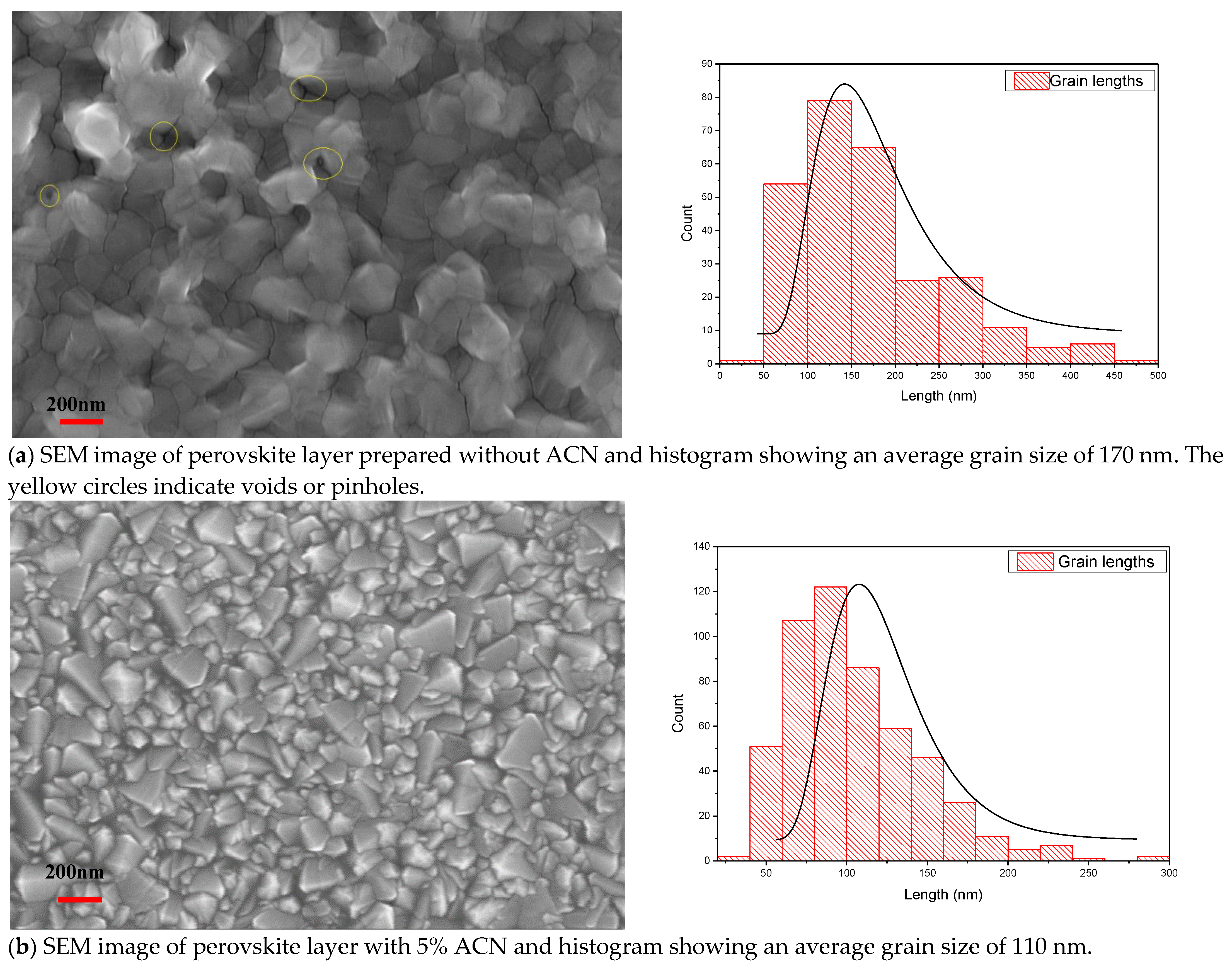
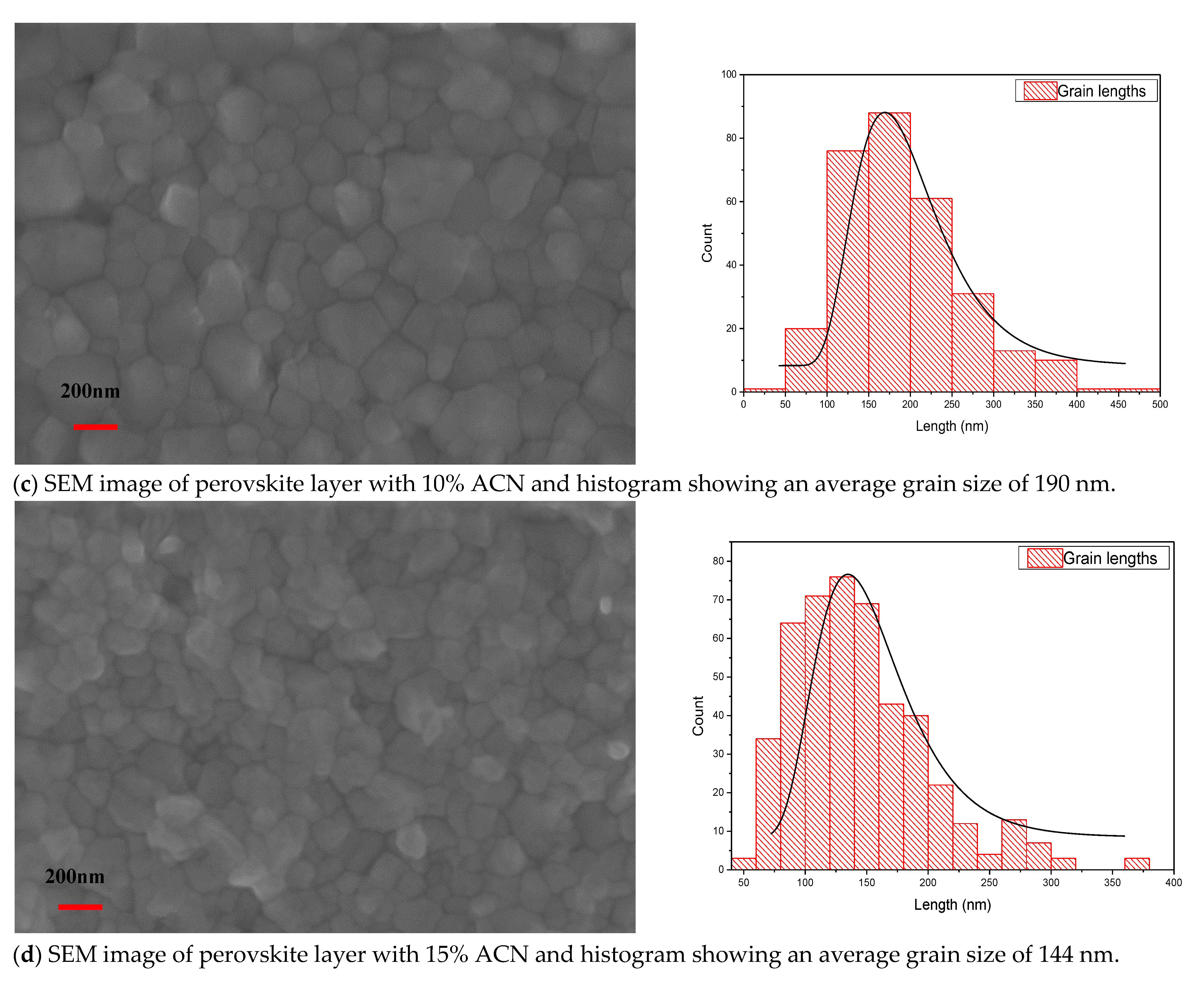
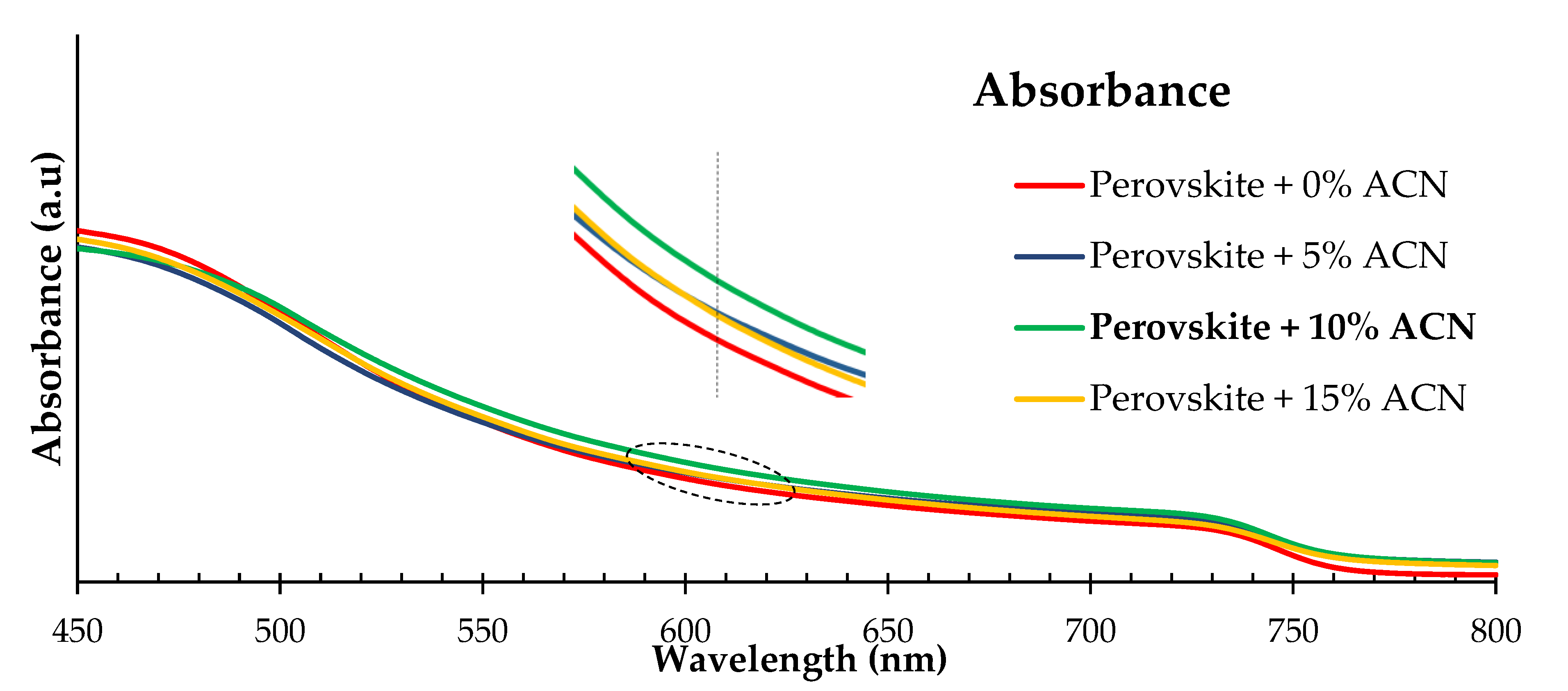
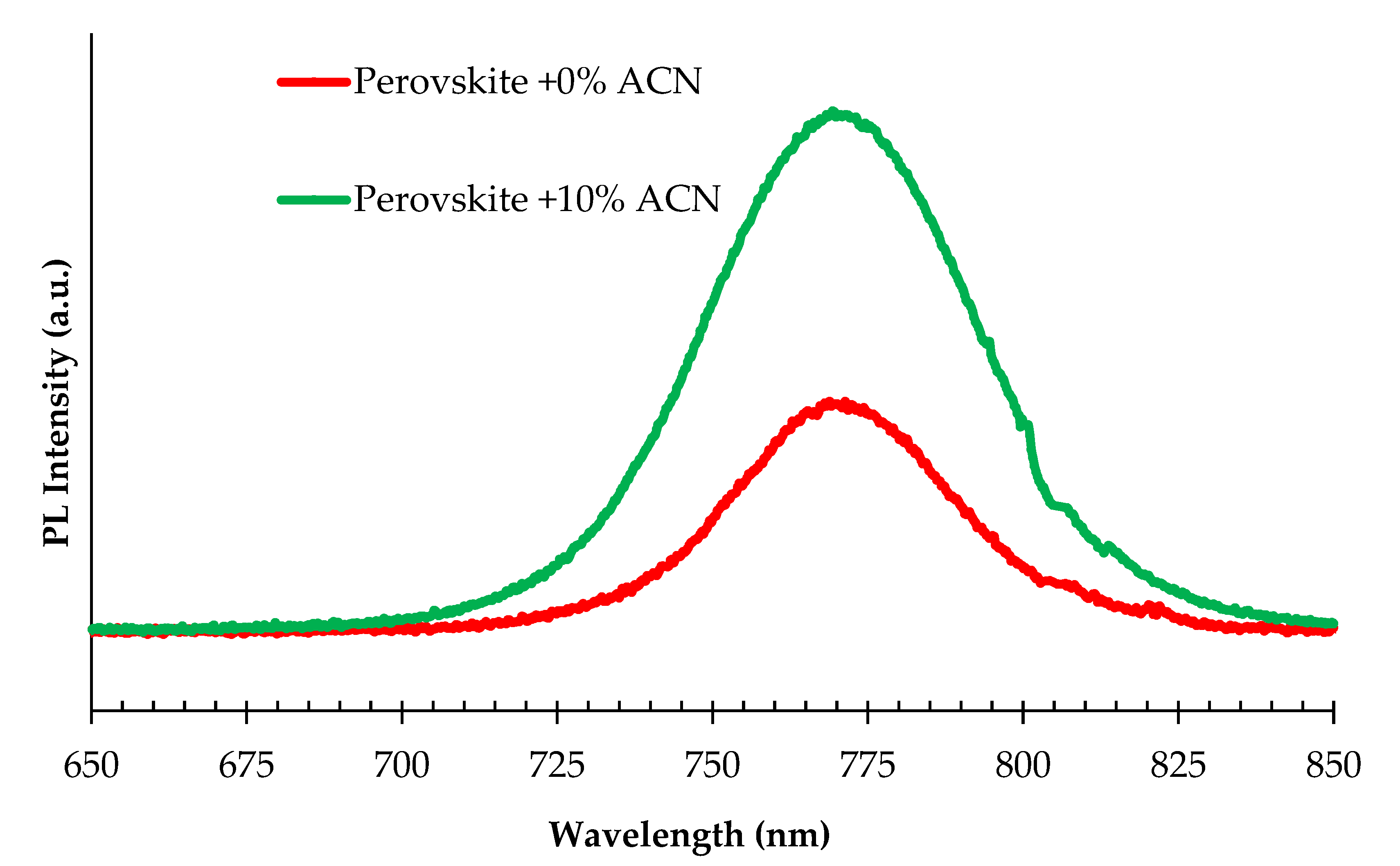
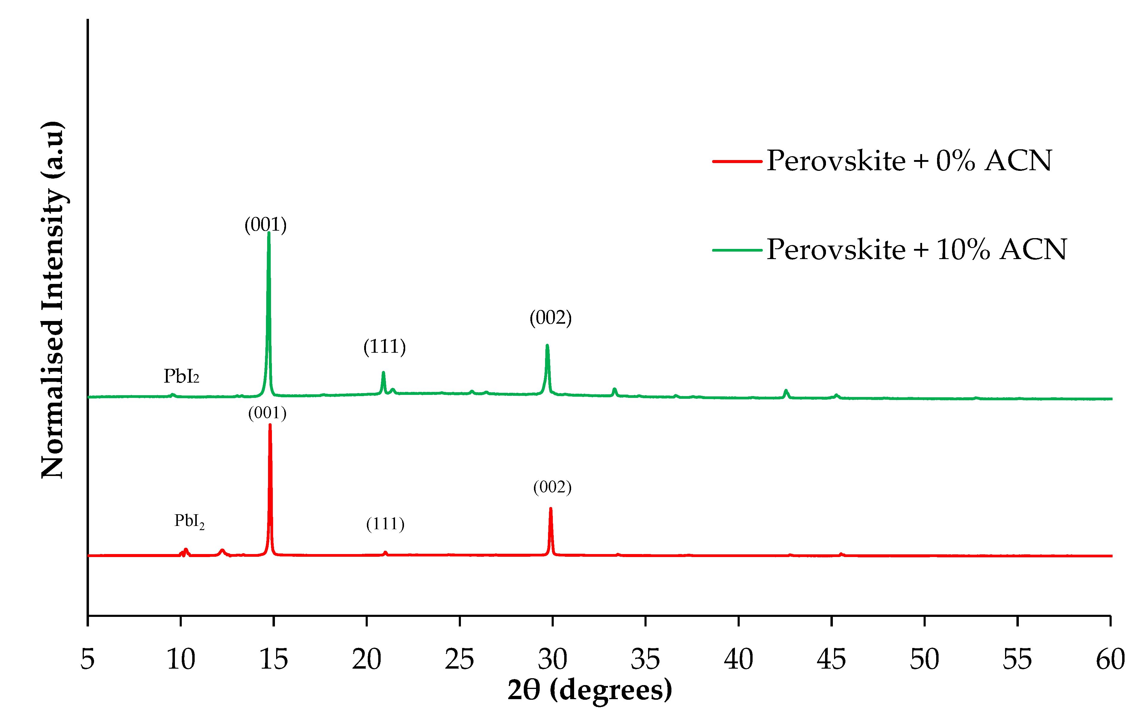
2.1. Structural and Optical Properties of Perovskite Films Fabricated under Ambient Air Laboratory Conditions

The analysis of defects in the materials using SEM images provides an important insight onto the material properties. The defects refer to irregularities or deviations from the expected or ideal structure in the material under analysis. It has been shown that ACN as a solvent additive can improve the surface properties by passivating the surface defects of the perovskite active layers [13]. Herein, the concentration ratio of ACN to the perovskite composition was changed from 5% to 15%. Using an optimum ratio of ACN in perovskite film led to an increase in the crystal grain size of the perovskite film and a decrease in the series resistance of the PSCs [16].
The grain size of the active perovskite films processed with 10% ACN are larger compared to films prepared without ACN, as illustrated in the SEM images shown in Figure 1. In addition, a reduction in pinholes or defects was observed. This was contrasted with the perovskite films prepared without ACN, which possess much higher density of defect states and pinholes, as shown in Figure 1a. High defect density has a negative effect on the performance of PSCs prepared without ACN [13]. Consequently, we found that the optimum ratio of ACN to perovskite precursor was 10% to achieve the desired performance of the PSCs. Perovskite material with a large grain size produces lower solar cell series resistance Rs, which leads to increased efficiency of the PSCs [6]. The SEM images show that the use of an optimum concentration of ACN in PSCs improves the perovskite crystal structure properties, which can boost the stability and the charge transport processes in perovskite devices [17,18].
It can be seen from Figure 2 that the perovskite active layer with 10% ACN gives a higher absorption coefficient value between the wavelength range 500–800 nm compared to other ratios of ACN additives. The 6% improvement in the absorption between the 500 and 700 nm wavelengths at 10% ACN might be behind the higher current density (Jsc) for devices prepared under these conditions, as shown in Table 1. The improvement in the perovskite film absorption spectra for samples prepared with 10% ACN is attributed to enlarged perovskite grain sizes, which results in lower recombination rates [17].
The energy gap, Eg, of the perovskite film without ACN and with various concentration ratios of ACN is fixed at 1.62 eV. This implies that there is a very small variation or change in the value of the Eg of the perovskite films when ACN is added. Figure 3 shows the absorbance edge of the perovskite film without ACN and with different ratios of ACN. The extracted energy gaps of the perovskite films do not change in value with the changing of the ACN ratio [19].
Figure 4 shows the photoluminescence (PL) spectrum of the pristine device (without ACN) and perovskite composition with 10% ACN. It is clear that there is an increase in the PL intensity indicating that the “non-radiative recombination” in the perovskite films was decreased when using 10% ACN. Non-radiative recombination refers to the process in which the excited electrons and holes in a material recombine and release energy as heat instead of light. In this case, the reduced non-radiative recombination in the existence of 10% ACN suggests that more energy was being released as light, which is desirable in PSCs as it can lead to higher efficiency [20]. This is due to the improvement of the perovskite film properties [21] and the reduction in the “grain boundary recombination” [22]. The results shown in Figure 4 are consistent with other work published elsewhere [13]. To study further the effects of the ACN additive on the crystalline structure and the surface quality of the perovskite films used in PSCs, XDR analysis was performed. The XRD spectra of the perovskite film without ACN and with 10% ACN are shown in Figure 5. The XRD results exhibited that as the content of the ACN additive in the perovskite composition increased, the intensity of the (001) plane of the perovskite film also increased, indicating a more desirable crystalline structure. This result is consistent with the results obtained from the PL, which showed improved device performance with the addition of 10% ACN as a result of decreasing the Rs value. Additionally, the XRD results showed a decrease in the intensity of the PbI2 peak in all films prepared with 10% ACN in contrast with the PbI2 peak observed in cells prepared without ACN. This has led to improved performance of the PSCs and the hysteresis suppression. Overall, the combination of XRD, PL, and SEM measurements provide important information on the crystal structure and surface quality of the perovskite films. The above analysis demonstrated a noticeable improvement in the optical properties and crystal structure of the perovskite films, which can lead to enhanced performance and charge transport in perovskite films [23,24].

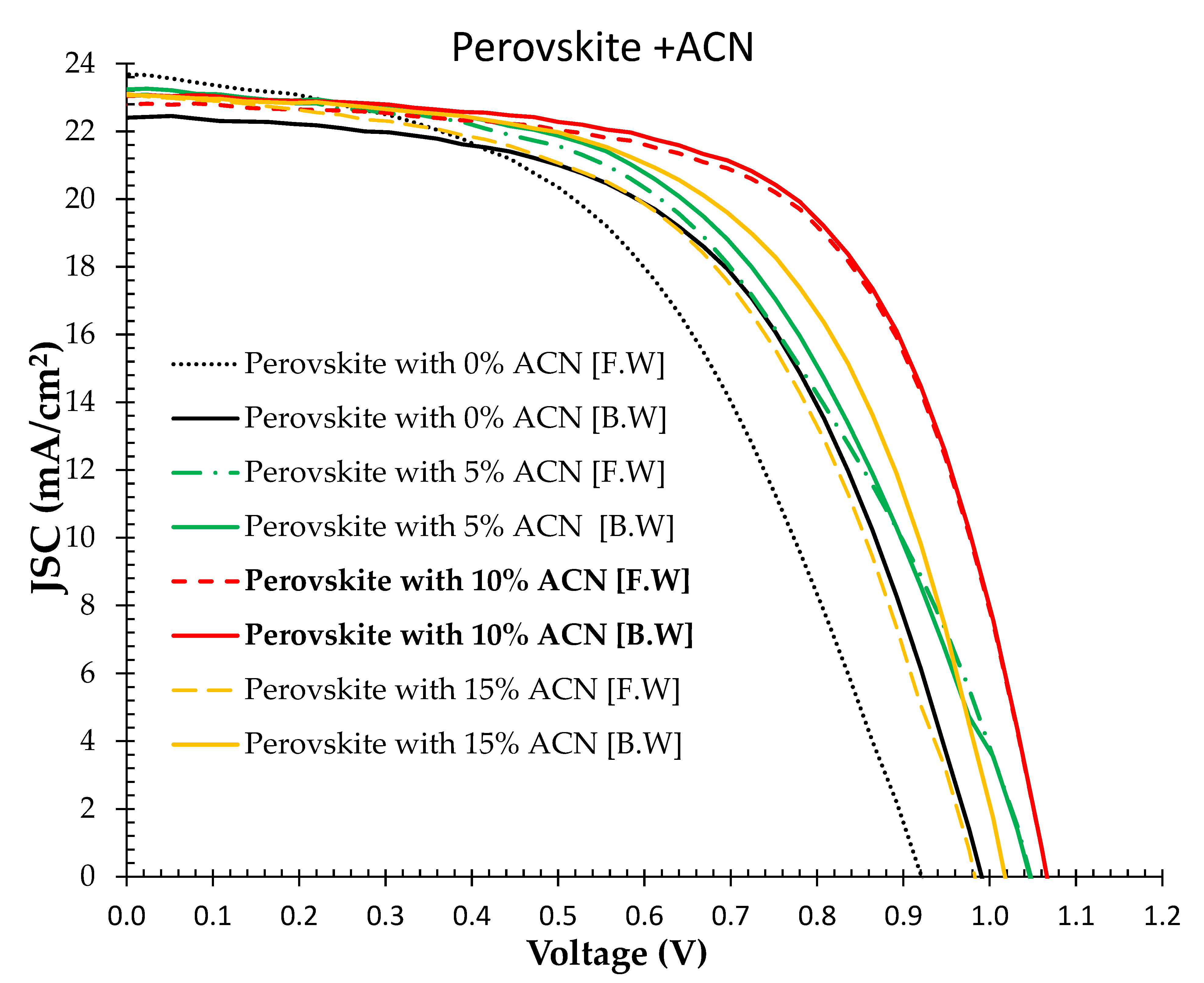
2.2. (J-V) Characteristics of PSC Devices Prepared under Ambient Air Laboratory Conditions Using Solvent Additive Technique

Different concentrations of ACN were added to the active perovskite films and were tested to study the optimum concentration of ACN that yielded the best device performance. It is clear from the J-V curves in Figure 6 that the solar cell characteristics of the perovskite film with 10% ACN shows higher efficiency (15.3%) compared to perovskite film without ACN (11.6%). This is an indicative that ACN suppresses non-radiative recombination in the perovskite film. Furthermore, owing to better surface quality with a larger grain size of the perovskite layer, the hysteresis phenomenon found in most perovskite-based devices is much less when ACN is added at a 10% ratio [13]. The perovskite prepared with 10% ACN gave an average PCE of 15.35%, which is about 30% more than perovskite fabricated without ACN. The perovskite prepared with 10% ACN shows 17% and 15% higher efficiency than the devices prepared with 5% ACN and 15% ACN, respectively. The Voc of the devices prepared with 10% ACN is 1055 mV, which is higher than other devices prepared with different ACN ratios. The improvements in the FF from 52% to 62% and in the Voc are due to the drop in the series resistance Rs from 12.5 to 7.85 Ω.cm2, as measured from the J-V curves. Moreover, this is also due to a decrease in non-radiative recombination in the perovskite devices, as indicated from the PL measurements [25]. Table 2 shows a summary of the parameters measured by others [13,19,26,27,28] using perovskite films with ACN as an additive technique and how they compare with our study. In general, devices fabricated under laboratory ambient air conditions processed with ACN have resulted in higher efficiency and a lower hysteresis effect compared to pristine cells. Moreover, this technique shows an easy method to fabricate PSCs with high efficiency under laboratory ambient air without a glovebox.

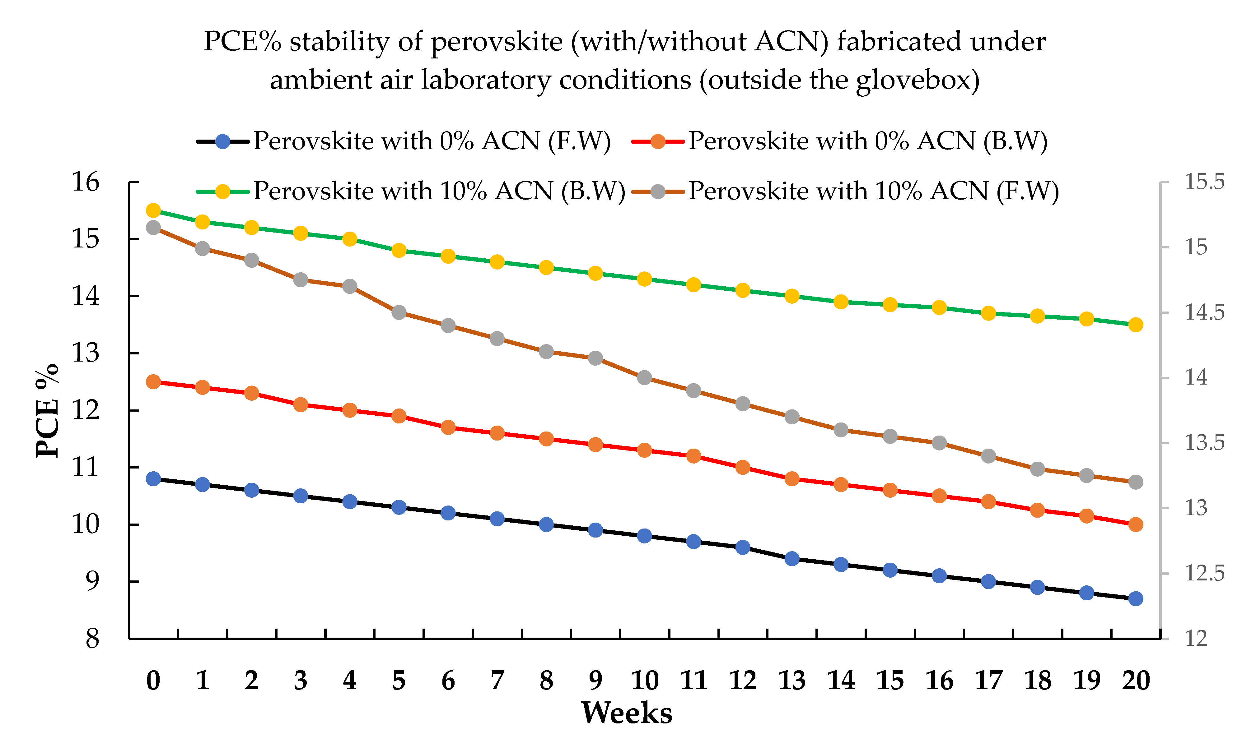
2.3. Stability of Perovskite Films with Solvent Additive Fabricated under Ambient Air Laboratory Conditions

The stability of the PSCs was studied by evaluating the efficiency of the devices over 20 weeks. To account for reproducibility, we took the average of five samples so the rates for forward and backward scans were similar. The devices were not encapsulated during the stability test. The illuminated J-V characteristics (sunlight simulator of 100 mW/cm2 intensity) were monitored over 20 weeks under ambient air laboratory conditions. The stability curves were taken by monitoring the efficiency measured from the forward and reverse J-V characteristic of the PSCs, as displayed in Figure 7. The decrease in efficiency was about 15% for perovskite films fabricated with 10% ACN, while the drop was 24% for the pristine samples (perovskite with 0% ACN) over the same period of 20 weeks. It is evident that using 10% ACN additive has resulted in improved stability and device performance in general compared to films without ACN.

3. Materials and Methods

3.1. Materials

All basic materials were supplied commercially and were utilized as received without any extra purification. Conductive Soda Lime glass fluorine-doped tin oxide (FTO, 12–15 Ω/sq) was sourced from MSE proTM supplies. Titanium dioxide (TiO2) paste (30NR-D), formamidinium iodide (FAI), and methylammonium bromide (MABr) were procured from greatcell solar. Lead (II) iodide (PbI2) 99.9% and lead (II) bromide (PbBr2) 99.9% were purchased from luminescence technology corp. (Lumtec). Bis(trifluoromethane)sulfonimide lithium salt (Li-TFSI 99.9%), acetonitrile anhydrous, (99.8%), spiro-MeOTAD 99% (HPLC), chlorobenzene (95%), tris(2-(1H-pyrazol-1-yl)-4-tert-utylpyridine)cobalt(III) tri[bis(trifluoromethane)sulfoni-mide] FK209 Co(III) TFSI salt, and 4-tert-Butylpyridine (TBP 98%) were bought from Sigma-Aldrich. Cesium iodide (CsI 99.998%) was purchased from Alfa Aesar. N,N-dimethylformamide (DMF, 99.5%) and dimethyl sulfoxide (DMSO, 99.9%) were acquired from Fisher Scientific (Waltham, MA, USA).

3.2. Methods

In this study, FTO glass substrate (12–15 Ω/sq) was utilized. The ETL in this study consisted of two main layers, which are compact TiO2 prepared using DC sputtering and mesoporous TiO2 prepared by dissolving 150 mg of TiO2 paste (30N-RD)/1 mL ethanol. The perovskite films were prepared and deposited on the ETL in ambient air laboratory (without using a glovebox). The main materials used in this study to prepare the perovskite compositions are FAI, MABr, PbI2, PbBr2, and CsI, with the concentrations mentioned in more detail in [12]. Then, the ACN solvent in different ratios (0%, 5%, 10% and 15%) was added to the perovskite composition while stirring for 20 min. The influence of the addition of different ratios of ACN to the perovskite precursors was then studied by analyzing the grain size, surface roughness, absorbance, XRD, and the illuminated characterization of the PSC devices. We dissolved 80 mg of spiro-MeOTAD in CBZ (1 mL) and added TBP and lithium salt to prepare the HTL [12]. The preparation of the active perovskite layer and both ETL and HTL are mentioned in more detail in [12,15]. Figure 8 shows the schematic diagram of the device used in this work.
The efficiency of devices was measured using ABET Sun3000 sunlight simulator AM 1.5G (100 mW/cm2) illumination, Milford, CT, USA and a Keithley meter. Ultraviolet–visible spectrometry (Cary 6000i) was used to measure the absorption spectrum of perovskite films without ACN and with different ratios of ACN. The morphology and surface grain size of the perovskite active layer without ACN and with different ratios of ACN were measured using a Raith-150 electron beam lithography EBL tool, Germany. A Rigaku Smart-Lab X-ray system, Japan was employed to measure the XRD spectra of the perovskite film with and without ACN. All the perovskite device measurements were conducted under laboratory ambient air.

4. Conclusions

PSCs fabricated under ambient air laboratory conditions using a solvent additive technique were investigated. Our results exhibited that using ACN increases the grain size of the perovskite films and passivates surface defects. The concentration ratio of ACN as an additive to the perovskite composition was changed from 5% to 15%. The optimum concentration of ACN was found to be 10% to enhance the charge transport processes in the device and the stability of the PSCs. Devices fabricated under ambient air laboratory conditions using ACN have demonstrated higher efficiencies than devices fabricated without ACN. Adding 10% ACN to the perovskite precursor increases the grain size of the perovskite film to 190 nm and reduces the Rs of the PSC to 7.85 Ω.cm2. This has also improved the FF of the PSC to 62%. The efficiency of cells with a perovskite layer prepared with 10% ACN fabricated under ambient air laboratory conditions is found to be 15.35% using a device active area of 0.36 cm2, which is 30% and 15% higher than perovskite fabricated under ambient air laboratory conditions without ACN and with 15% ACN, respectively. The perovskite material prepared with 10% ACN shows a 17% higher efficiency than perovskite prepared with 5% ACN. The ACN additive improves the stability and decreases the hysteresis phenomenon found in most PSCs. The drop in efficiency over 20 weeks was around 15% for the perovskite film processed with 10% ACN, while the drop was 24% for pristine devices (perovskite with 0% ACN). Our results showed that the addition of 10% ACN exhibited a 37% improvement in the stability of PSCs over devices without ACN. This study demonstrates a simple method for preparing highly efficient PSCs under ambient air laboratory conditions and the effective use of ACN in PSC fabrication.

Author Contributions

A.H. conceived the original idea, performed the experimental work, and wrote draft of the manuscript. M.M.A. supervised the work, performed analysis, contributed to the discussion of the results, and revised the manuscript. All authors have read and agreed to the published version of the manuscript.

Funding

A.H: acknowledges the UC Doctoral Scholarship funding, University of Canterbury, New Zealand. M.M.A and R.J.R acknowledge the support of the MacDiarmid Institute for Advanced Materials and Nanotechnology, New Zealand. MI funding number: 432D1MMA:E6360:1.

Institutional Review Board Statement

Not applicable.

Informed Consent Statement

Not applicable.

Data Availability Statement

The original contributions presented in the study are included in the article, further inquiries can be directed to the corresponding author.

Acknowledgments

The authors would like to thank Roger Reeves, Linda Chen, Gary Turner, and Helen Devereux from the Nanofabrication Laboratory, University of Canterbury, New Zealand, for providing technical assistance.

Conflicts of Interest

The authors declare no conflicts of interest.

References

  1. Kojima, A.; Teshima, K.; Shirai, Y.; Miyasaka, T. Organometal Halide Perovskites as Visible-Light Sensitizers for Photovoltaic Cells. J. Am. Chem. Soc. 2009, 131, 6050–6051. [Google Scholar] [CrossRef] [PubMed]
  2. Zheng, Y.; Li, Y.; Zhuang, R.; Wu, X.; Tian, C.; Sun, A.; Chen, C.; Guo, Y.; Hua, Y.; Meng, K.; et al. Towards 26% Efficiency in Inverted Perovskite Solar Cells via Interfacial Flipped Band Bending and Suppressed Deep-Level Traps. Energy Environ. Sci. 2023, 17, 1153–1162. [Google Scholar] [CrossRef]
  3. Jeon, N.J.; Noh, J.H.; Yang, W.S.; Kim, Y.C.; Ryu, S.; Seo, J.; Seok, S.I. Compositional Engineering of Perovskite Materials for High-Performance Solar Cells. Nature 2015, 517, 476–480. [Google Scholar] [CrossRef] [PubMed]
  4. Zuo, L.; Gu, Z.; Ye, T.; FU, W.; Wu, G.; Li, H.; Chen, H. Enhanced Photovoltaic Performance of CH3NH3PbI3 Perovskite Solar Cells through Interfacial Engineering Using Self-Assembling Monolayer. J. Am. Chem. Soc. 2015, 137, 2674–2679. [Google Scholar] [CrossRef] [PubMed]
  5. Mahapatra, A.; Prochowicz, D.; Tavakoli, M.M.; Trivedi, S.; Kumar, P.; Yadav, P. A Review of Aspects of Additive Engineering in Perovskite Solar Cells. J. Mater. Chem. A 2020, 8, 27–54. [Google Scholar] [CrossRef]
  6. Jeon, N.J.; Noh, J.H.; Kim, Y.C.; Yang, W.S.; Ryu, S.; Seok, S.I. Solvent Engineering for High-Performance Inorganic-Organic Hybrid Perovskite Solar Cells. Nat. Mater. 2014, 13, 897–903. [Google Scholar] [CrossRef] [PubMed]
  7. Liu, X.; Zhang, Z.; Lin, F.; Cheng, Y. Structural Modulation and Assembling of Metal Halide Perovskites for Solar Cells and Light-emitting Diodes. InfoMat 2021, 3, 1218–1250. [Google Scholar] [CrossRef]
  8. Cheng, Y.; Li, M.; Liu, X.; Cheung, S.H.; Chandran, H.T.; Li, H.W.; Xu, X.; Xie, Y.M.; So, S.K.; Yip, H.L.; et al. Impact of Surface Dipole in NiOx on the Crystallization and Photovoltaic Performance of Organometal Halide Perovskite Solar Cells. Nano Energy 2019, 61, 496–504. [Google Scholar] [CrossRef]
  9. Li, M.; Yue, Z.; Ye, Z.; Li, H.; Luo, H.; Yang, Q.-D.; Zhou, Y.; Huo, Y.; Cheng, Y. Improving the Efficiency and Stability of MAPbI3 Perovskite Solar Cells by Dipeptide Molecules. Small 2024, 20, 2311400. [Google Scholar] [CrossRef]
  10. Tai, Q.; You, P.; Sang, H.; Liu, Z.; Hu, C.; Chan, H.L.W.; Yan, F. Efficient and Stable Perovskite Solar Cells Prepared in Ambient Air Irrespective of the Humidity. Nat. Commun. 2016, 7, 11105. [Google Scholar] [CrossRef]
  11. Mesquita, I.; Andrade, L.; Mendes, A. Effect of Relative Humidity during the Preparation of Perovskite Solar Cells: Performance and Stability. Sol. Energy 2020, 199, 474–483. [Google Scholar] [CrossRef]
  12. Hayali, A.; Alkaisi, M.M. High Efficiency Perovskite Solar Cells Using DC Sputtered Compact TiO2electron Transport Layer. EPJ Photovolt. 2021, 12, 8. [Google Scholar] [CrossRef]
  13. Hussein, H.T.; Zamel, R.S.; Mohamed, M.S.; Mohammed, M.K.A. High-Performance Fully-Ambient Air Processed Perovskite Solar Cells Using Solvent Additive. J. Phys. Chem. Solids 2021, 149, 109792. [Google Scholar] [CrossRef]
  14. Cheng, Y.; Xu, X.; Xie, Y.; Li, H.W.; Qing, J.; Ma, C.; Lee, C.S.; So, F.; Tsang, S.W. 18% High-Efficiency Air-Processed Perovskite Solar Cells Made in a Humid Atmosphere of 70% RH. Sol. RRL 2017, 1, 1700097. [Google Scholar] [CrossRef]
  15. Hayali, A.; Reeves, R.J.; Alkaisi, M.M. Wavelength Selective Solar Cells Using Triple Cation Perovskite. Nanomaterials 2022, 12, 3299. [Google Scholar] [CrossRef]
  16. Gao, L.; Yang, G. Organic-Inorganic Halide Perovskites: From Crystallization of Polycrystalline Films to Solar Cell Applications. Sol. RRL 2020, 4, 1900200. [Google Scholar] [CrossRef]
  17. Bu, T.; Liu, X.; Zhou, Y.; Yi, J.; Huang, X.; Luo, L.; Xiao, J.; Ku, Z.; Peng, Y.; Huang, F.; et al. A Novel Quadruple-Cation Absorber for Universal Hysteresis Elimination for High Efficiency and Stable Perovskite Solar Cells. Energy Environ. Sci. 2017, 10, 2509–2515. [Google Scholar] [CrossRef]
  18. Moore, D.T.; Sai, H.; Tan, K.W.; Smilgies, D.M.; Zhang, W.; Snaith, H.J.; Wiesner, U.; Estroff, L.A. Crystallization Kinetics of Organic-Inorganic Trihalide Perovskites and the Role of the Lead Anion in Crystal Growth. J. Am. Chem. Soc. 2015, 137, 2350–2358. [Google Scholar] [CrossRef] [PubMed]
  19. Yang, Y.; Wu, J.; Wu, T.; Xu, Z.; Liu, X.; Guo, Q.; He, X. An Efficient Solvent Additive for the Preparation of Anion-Cation-Mixed Hybrid and the High Performance Perovskite Solar Cells. J. Colloid Interface Sci. 2018, 531, 602–608. [Google Scholar] [CrossRef]
  20. Nie, W.; Tsai, H.; Asadpour, R.; Neukirch, A.J.; Gupta, G.; Crochet, J.J.; Chhowalla, M.; Tretiak, S.; Alam, M.A.; Wang, H. High-Efficiency Solution-Processed Perovskite Solar Cells with Millimeter-Scale Grains. Science 2015, 347, 522–526. [Google Scholar] [CrossRef]
  21. Yang, B.; Han, K. Charge-Carrier Dynamics of Lead-Free Halide Perovskite Nanocrystals. Acc. Chem. Res. 2019, 52, 3188–3198. [Google Scholar] [CrossRef] [PubMed]
  22. Prochowicz, D.; Tavakoli, M.M.; Wolska-Pietkiewicz, M.; Jędrzejewska, M.; Trivedi, S.; Kumar, M.; Zakeeruddin, S.M.; Lewiński, J.; Graetzel, M.; Yadav, P. Suppressing Recombination in Perovskite Solar Cells via Surface Engineering of TiO2 ETL. Sol. Energy 2020, 197, 50–57. [Google Scholar] [CrossRef]
  23. Park, B.W.; Kedem, N.; Kulbak, M.; Lee, D.Y.; Yang, W.S.; Jeon, N.J.; Seo, J.; Kim, G.; Kim, K.J.; Shin, T.J.; et al. Understanding How Excess Lead Iodide Precursor Improves Halide Perovskite Solar Cell Performance. Nat. Commun. 2018, 9, 3301. [Google Scholar] [CrossRef] [PubMed]
  24. Jiang, Q.; Zhang, L.; Wang, H.; Yang, X.; Meng, J.; Liu, H.; Yin, Z.; Wu, J.; Zhang, X.; You, J. Enhanced Electron Extraction Using SnO2 for High-Efficiency Planar-Structure HC(NH2)2PbI3-Based Perovskite Solar Cells. Nat. Energy 2017, 2, 16177. [Google Scholar] [CrossRef]
  25. Wolff, C.M.; Caprioglio, P.; Stolterfoht, M.; Neher, D. Nonradiative Recombination in Perovskite Solar Cells: The Role of Interfaces. Adv. Mater. 2019, 31, 1902762. [Google Scholar] [CrossRef] [PubMed]
  26. Li, L.; Chen, Y.; Liu, Z.; Chen, Q.; Wang, X.; Zhou, H. The Additive Coordination Effect on Hybrids Perovskite Crystallization and High-Performance Solar Cell. Adv. Mater. 2016, 28, 9862–9868. [Google Scholar] [CrossRef]
  27. Li, H.; Xia, Y.; Wang, C.; Wang, G.; Chen, Y.; Guo, L.; Luo, D.; Wen, S. High-Efficiency and Stable Perovskite Solar Cells Prepared Using Chlorobenzene/Acetonitrile Antisolvent. ACS Appl. Mater. Interfaces 2019, 11, 34989–34996. [Google Scholar] [CrossRef]
  28. Tao, H.; Li, Y.; Zhang, C.; Wang, K.; Tan, B.; Wang, J.; Tao, J. Efficiency Enhancement of Perovskite Solar Cells by Forming a Tighter Interface Contact of C/CH3NH3PbI3. J. Phys. Chem. Solids 2018, 123, 25–31. [Google Scholar] [CrossRef]
Figure 1. SEM images of the surface morphology of perovskite films (a) without ACN and with (b) 5% ACN, (c) 10% ACN, and (d) 15% ACN.
Inorganics 12 00214 g001aInorganics 12 00214 g001b
Figure 2. The optical absorption of various concentrations of perovskite films without ACN and with 5% ACN, 10% ACN, and 15% ACN.
Inorganics 12 00214 g002
Figure 3. Extrapolation of energy gap of perovskite films without ACN and with 5% ACN, 10% ACN, and 15% ACN using Tauc plot.
Inorganics 12 00214 g003
Figure 4. The photoluminescence (PL) spectra of control device (ACN 0%) and perovskite film with 10% ACN.
Inorganics 12 00214 g004
Figure 5. XED pattern spectra of the perovskite films without ACN and with 10% ACN.
Inorganics 12 00214 g005
Figure 6. J-V characteristic curves of PSC devices with the perovskite layer with and without ACN. The preparations of the perovskite films were conducted in a laboratory ambient air condition of 45% humidity and 24 °C temperature using a two-steps spin coating deposition method. Both forward and backward bias scans are shown in the figure for comparison.
Inorganics 12 00214 g006
Figure 7. PSC stability monitored for 20 weeks by measuring the efficiency of the devices every week.
Inorganics 12 00214 g007
Figure 8. A schematic diagram of the PSCs used in this study.
Inorganics 12 00214 g008
Table 1. Key parameters for solar cells measured for active perovskite layer without ACN (0%) and 5%, 10%, and 15% ACN using a two-step spin coating deposition process. Active area in all devices tested was 0.36 cm2.
Sample
Description
Sweep DirectionEFF%FF%Voc
[mV]
Jsc
[mA/cm2]
Vmax [mV]Jmax [mA/cm2]Isc
[mA]
Rshunt
[Ω.cm2]
Rseries
[Ω.cm2]
Perovskite with 0% ACN (control) was fabricated under laboratory ambient air FW10.849.592123.758418.58.496213
BW12.55699022.4696188.1140312
Avg.11.652.79552364018.28.2118212.5
Perovskite with 5% ACN was fabricated under laboratory ambient airFW12.65210472366818.98.370112
BW13.153.8104623.269618.88.3700411
Avg.12.852.9104623.168218.88.3385211.5
Perovskite with 10% ACN was fabricated under laboratory ambient airFW15.261104422.476419.58.0675627.8
BW15.56310662378019.98.377167.9
Avg.15.3562105522.777219.78.1876397.85
Perovskite with 15% ACN was fabricated under laboratory ambient airFW12.3549832366818.358.24209.4
BW13.758.510172372418.98.39558.6
Avg.1356.210002369618.68.26879
Table 2. Summary of efficiency improvement obtained from other published work using ACN as an additive technique as compared with this study.
ReferencesFabrication AtmosphereTechnique of FabricationUsing ACN as Additive TechniqueComposition of PerovskiteActive
Area cm2
Efficiency Improvement
[13]Laboratory ambient airSequential deposition processCation perovskite precursor + CAN(CsMAFA)Pb (IBr)3-20%
[19]Dry atmosphere in a gloveboxOne-step processCation perovskite precursor + ACN(CsMAFA)Pb (IBr)30.129.6%
[26]N2Sequential deposition processPbI2 precursor + ACNCH3NH3PbI3-18.5%
[27]GloveboxOne-step processACN + CBZ anti-solventCH3NH3PbI3-16.6%
[28]Not mentionedTwo-step processCarbon slurry + ACNCH3NH3PbI30.1011.5%
Our workNot mentionedTwo-steps spin-coatingTriple cation perovskite precursor + ACNCsI0.05[(FAPbI3)0.85(MAPbBr3)0.15]0.950.3625%
Disclaimer/Publisher’s Note: The statements, opinions and data contained in all publications are solely those of the individual author(s) and contributor(s) and not of MDPI and/or the editor(s). MDPI and/or the editor(s) disclaim responsibility for any injury to people or property resulting from any ideas, methods, instructions or products referred to in the content.

