
Preparation of Non-Noble Metal Catalyst FeCo2O4/MoS2 for Production of Hydrogen and Oxygen by Electrochemical Decomposition of Water

 ,
,
Abstract
1. Introduction
2. Results and Discussion
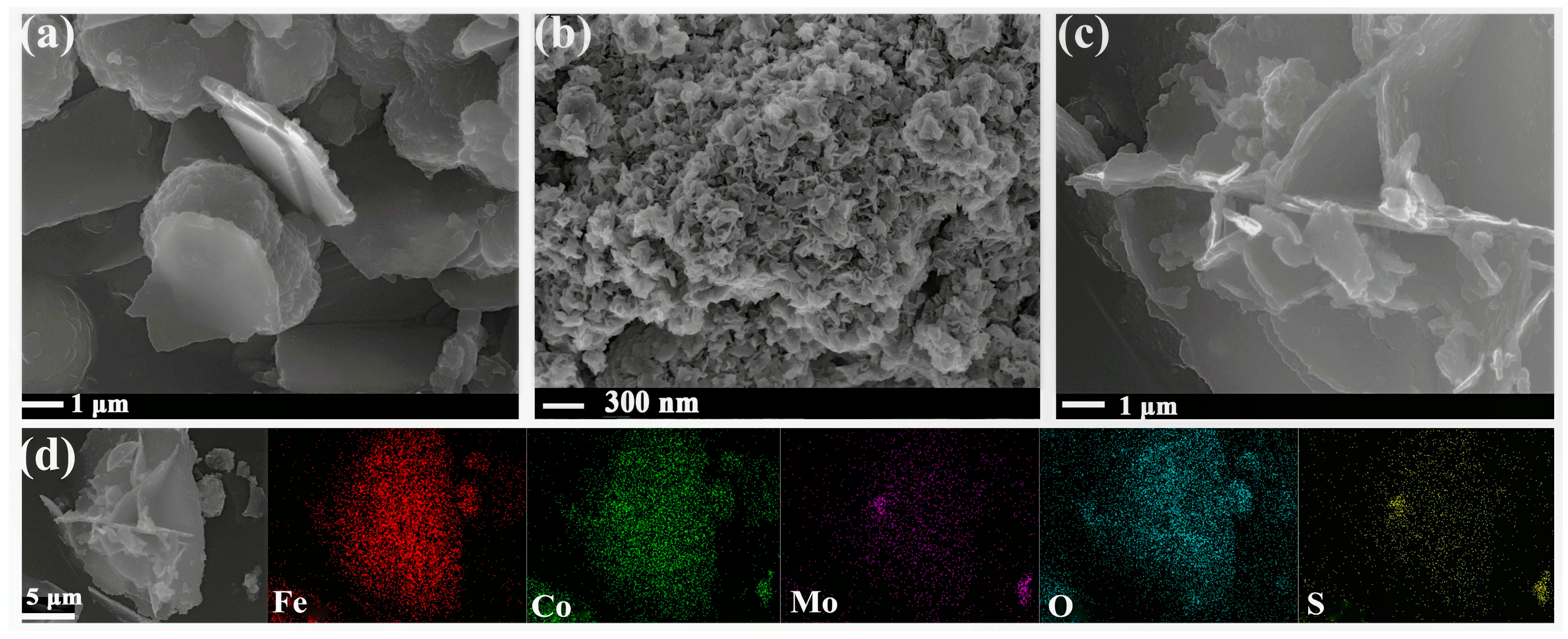
2.1. SEM and EDS Analysis
2.2. XRD Analysis
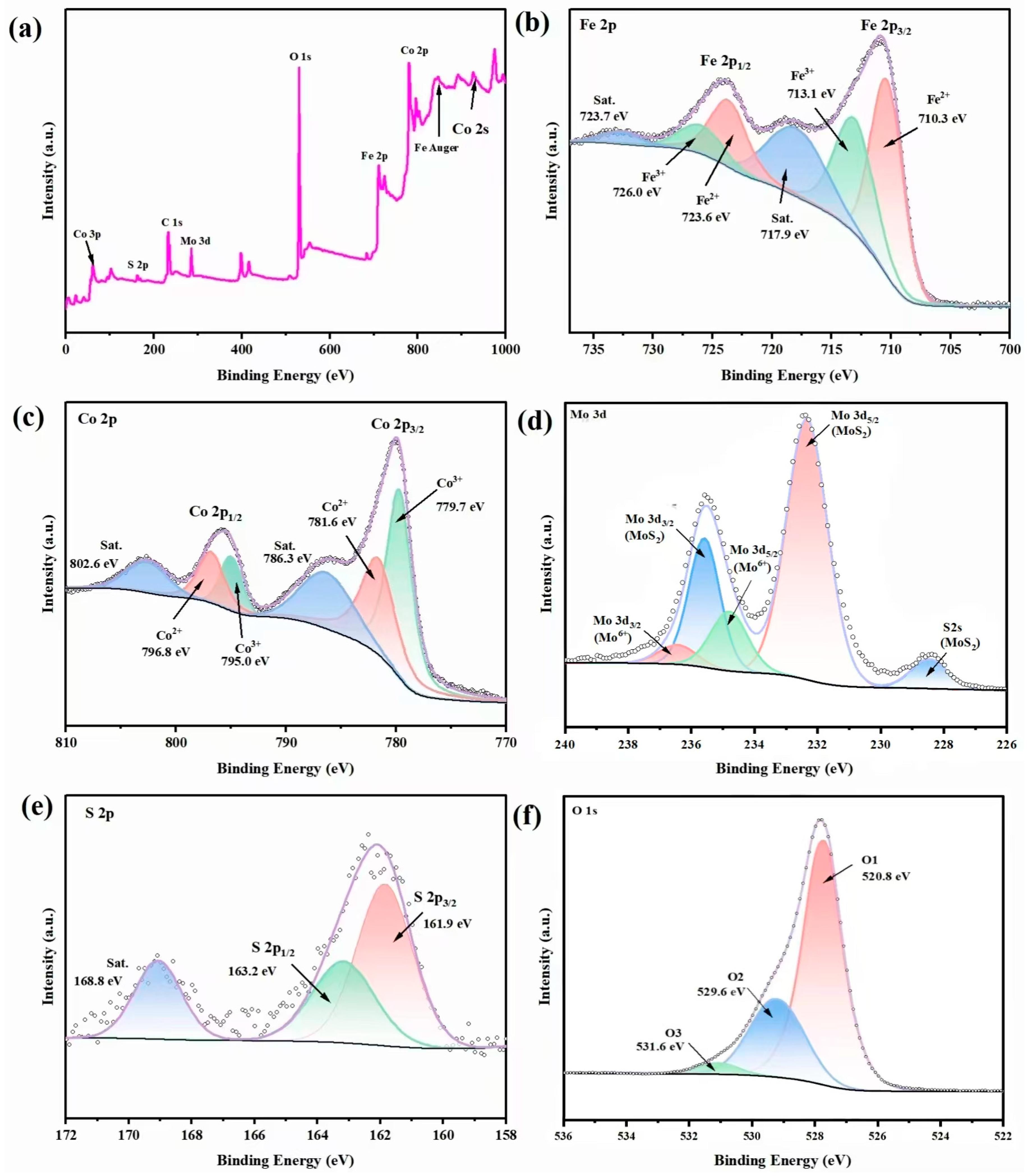
2.3. XPS Analysis
2.4. Electrochemical Properties of Catalysts
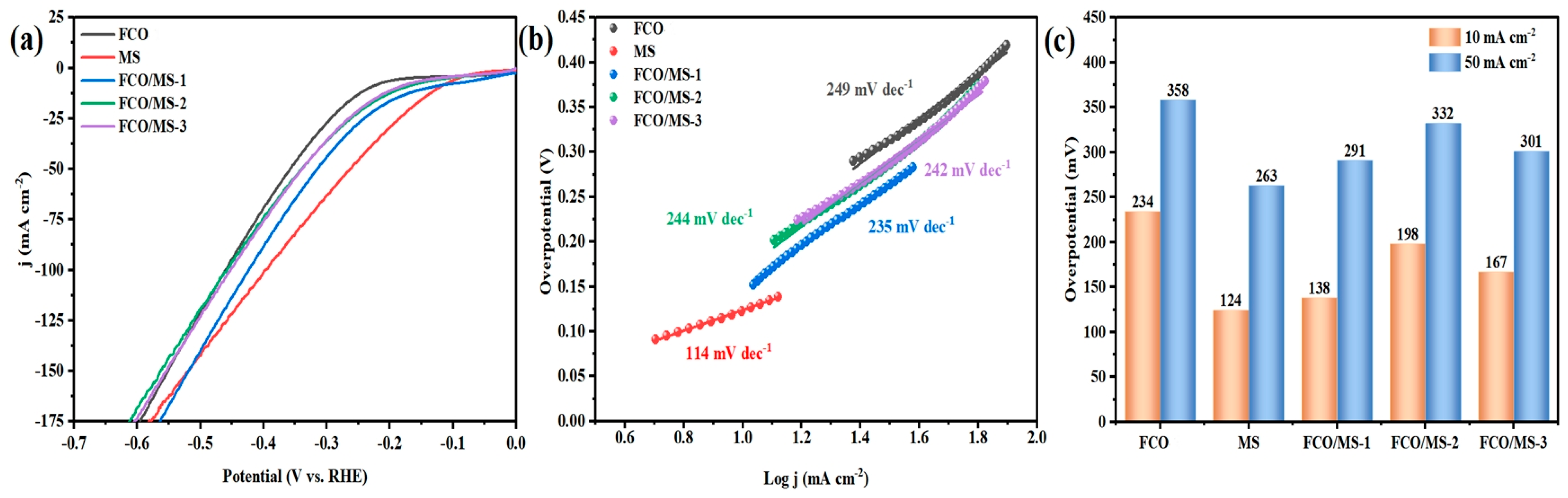
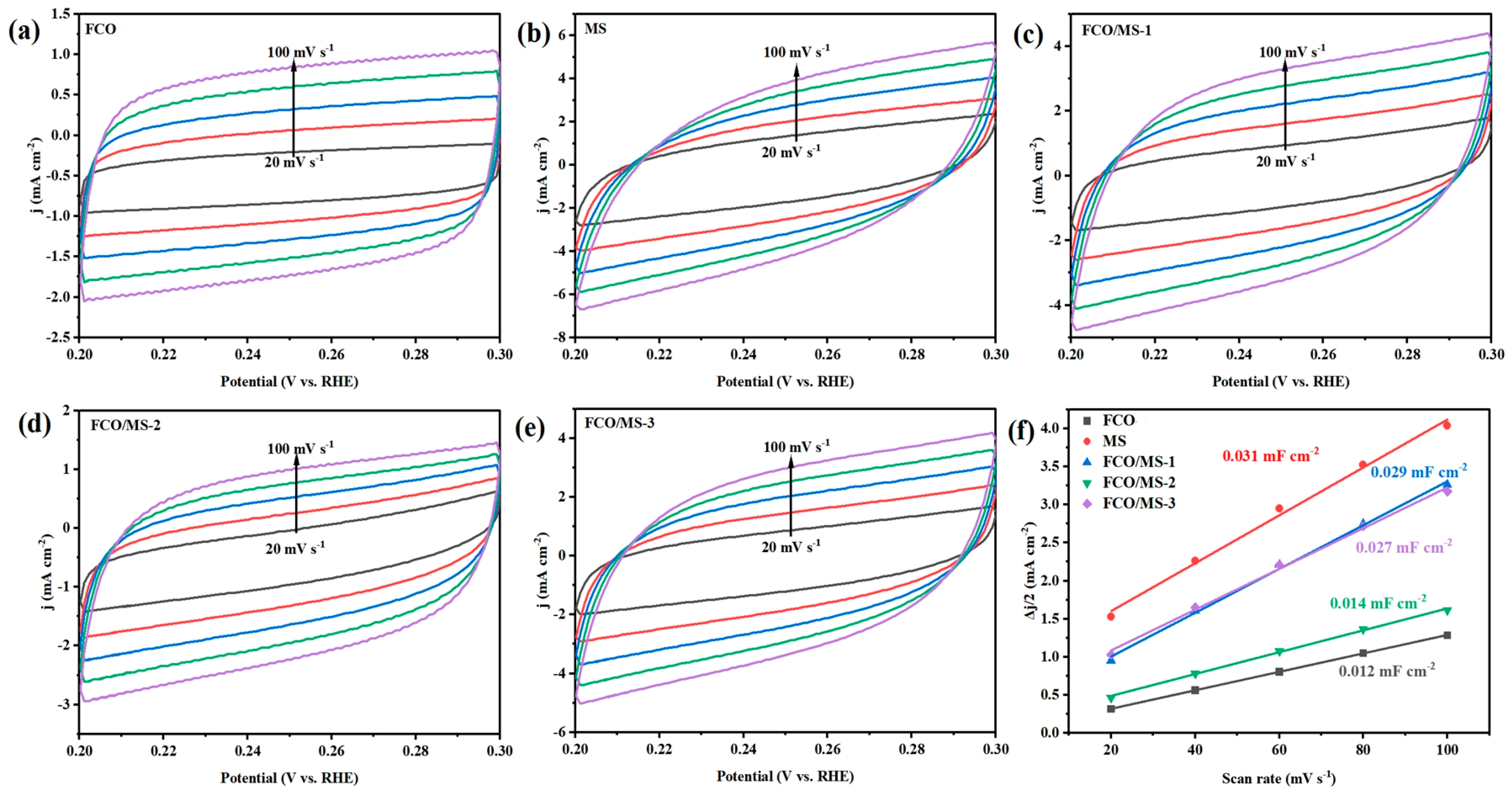
2.4.1. Hydrogen Evolution Performance
2.4.2. Oxygen Evolution Performance
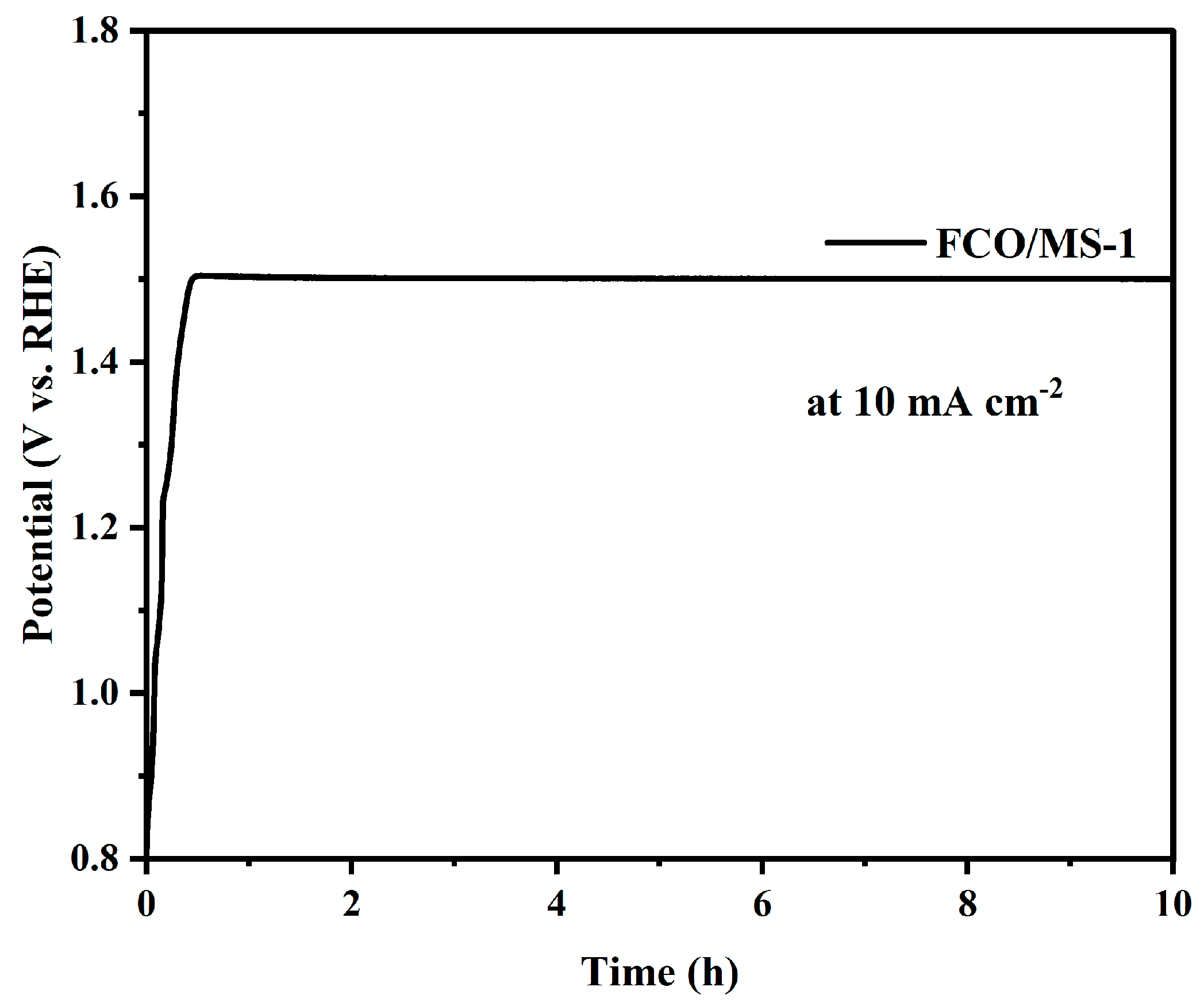
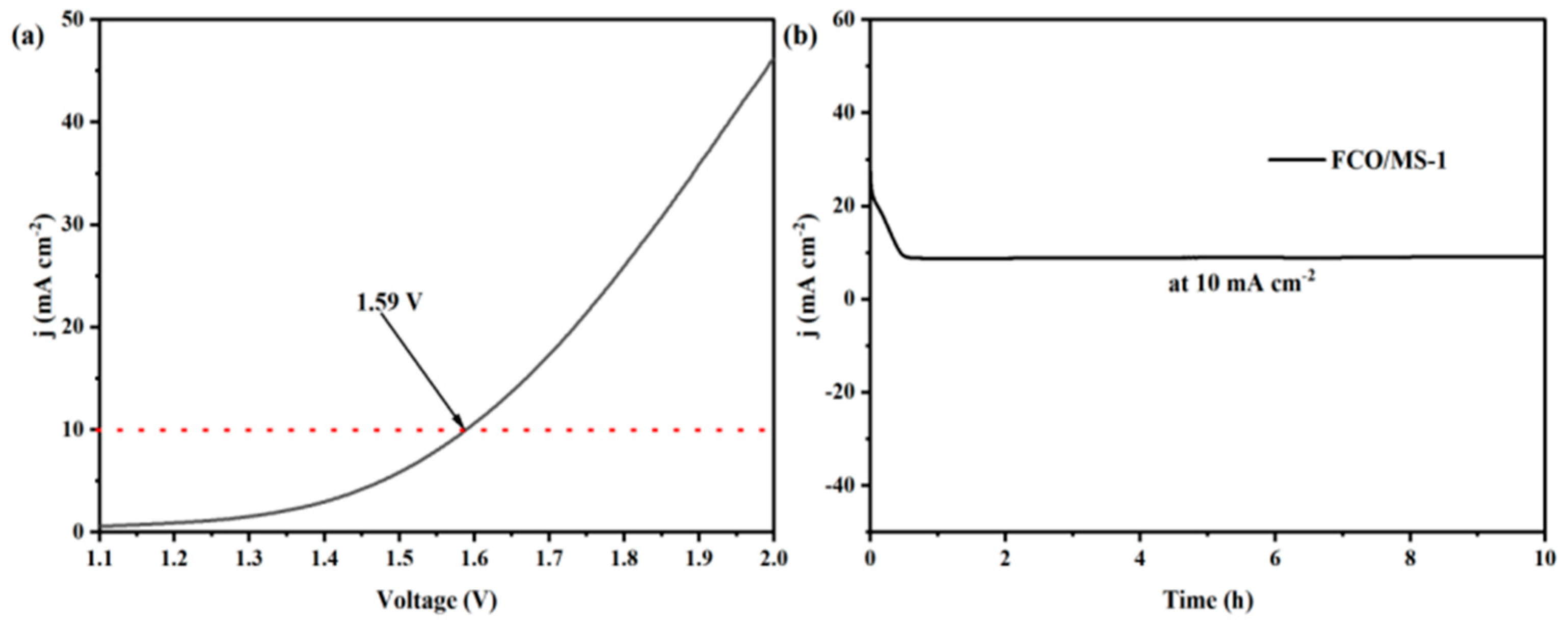
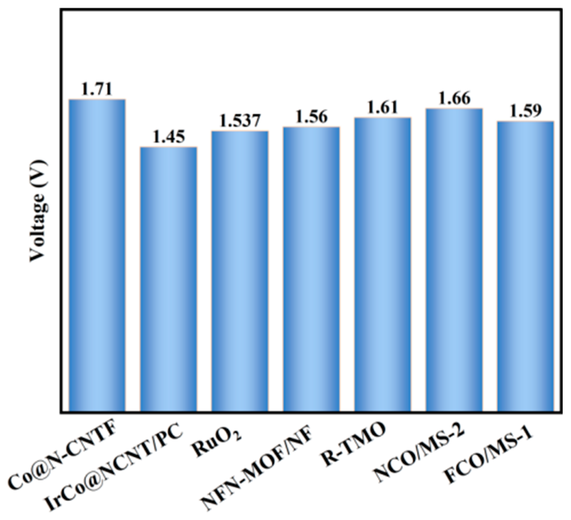
2.4.3. Performance of FeCo2O4/MoS2 Catalyst under Overall Water Splitting
3. Experimental Section
3.1. Materials
3.2. Preparation Process
3.2.1. Preparation of FeCo2O4
3.2.2. Preparation of MoS2
3.2.3. Preparation of FeCo2O4/MoS2
3.3. Characterization
3.4. Electrochemical Performance Test
4. Conclusions
Author Contributions
Funding
Data Availability Statement
Acknowledgments
Conflicts of Interest
References
- Huang, J.; Jiang, Y.; An, T.; Cao, M. Increasing the active sites and intrinsic activity of transition metal chalcogenide electrocatalysts for enhanced water splitting. J. Mater. Chem. A 2020, 8, 25465–25498. [Google Scholar] [CrossRef]
- Wang, S.; Lu, A.; Zhong, C.J. Hydrogen production from water electrolysis: Role of catalysts. Nano Converg. 2021, 8, 4–27. [Google Scholar] [CrossRef]
- Turner, J.A. Sustainable Hydrogen Production. Science 2004, 305, 972–974. [Google Scholar] [CrossRef]
- Niksa, S. FLASHCHAIN Theory for Rapid Coal Devolatilization Kinetics. 10. Extents of Conversion for Hydropyrolysis and Hydrogasification of Any Coal. Energy Fuels 2018, 32, 384–395. [Google Scholar] [CrossRef]
- Muradov, N. Hydrogen via methane decomposition: An application for decarbonization of fossil fuels. Int. J. Hydrogen Energy 2001, 26, 1165–1175. [Google Scholar] [CrossRef]
- Abdelhamid, H.N. A review on hydrogen generation from the hydrolysis of sodium borohydride. Int. J. Hydrogen Energy 2021, 46, 726–765. [Google Scholar] [CrossRef]
- Torres-Pinto, A.; Sampaio, M.J.; Silva, C.G.; Faria, J.L. Recent Strategies for Hydrogen Peroxide Production by Metal-Free Carbon Nitride Photocatalysts. Catalysts 2019, 9, 990. [Google Scholar] [CrossRef]
- Zhang, J.; Zhang, Q.; Feng, X. Support and interface effects in water-splitting electrocatalysts. Adv. Mater. 2019, 31, 8167–8186. [Google Scholar] [CrossRef]
- Shang, X.; Liu, Z.Z.; Lu, S.S.; Dong, B.; Chi, J.Q.; Qin, J.F.; Liu, X.; Chai, Y.M.; Liu, C.G. Pt-C interfaces based on electronegativity-functionalized hollow carbon spheres for highly efficient hydrogen evolution. ACS Appl. Mater. Interfaces 2018, 10, 43561. [Google Scholar] [CrossRef]
- Cherevko, S.; Geiger, S.; Kasian, O.; Kuiyk, N.; Grote, J.; Savan, A.; Shrestha, B.R.; Merzlikin, S.; Breitbach, B.; Ludwig, A.; et al. Oxygen and hydrogen evolution reactions on Ru, RuO2, Ir, and IrO2 thin film electrodes in acidic and alkaline electrolytes: A comparative study on activity and stability. Catal. Today 2016, 262, 170–180. [Google Scholar] [CrossRef]
- Tang, S.; Zhou, X.; Liu, T.; Zhang, S.; Yang, T.; Luo, Y.; Sharman, E.; Jiang, J. Single nickel atom supported on hybridized graphene-boronnitride nanosheet as a highly active bi-functional electrocatalyst for hydrogen and oxygen evolution reactions. J. Mater. Chem. A 2019, 7, 26261–26265. [Google Scholar] [CrossRef]
- Bu, Y.; Jang, H.; Gwon, O.; Kim, S.; Joo, S.; Nam, G.; Kim, S.; Qin, Y.; Zhong, Q.; Kwak, S. Synergistic interaction of perovskite oxides and N-doped graphene in versatile electrocatalyst. J. Mater. Chem. A 2019, 7, 2048–2054. [Google Scholar] [CrossRef]
- Guo, H.; Feng, Q.; Zhu, J.; Xu, J.; Li, Q.; Liu, S.; Xu, K.; Zhang, C.; Liu, T. Cobalt nanoparticle-embedded nitrogen-doped carbon/carbon nanotube frameworks derived from a metal-organic framework for tri-functional ORR, OER and HER electrocatalysis. J. Mater. Chem. A 2019, 7, 3664–3672. [Google Scholar] [CrossRef]
- Yu, H.; Xue, Y.; Hui, L.; He, F.; Zhang, C.; Liu, Y.; Fang, Y.; Xing, C.; Li, Y.; Liu, H.; et al. Graphdiyne-engineered heterostructures for efficient overall water-splitting. Nano Energy 2019, 64, 103928. [Google Scholar] [CrossRef]
- Gao, J.; Li, Y.; Yu, X.; Ma, Y. Graphdiyne reinforced multifunctional Cu/Ni bimetallic Phosphides-Graphdiyne hybrid nanostructure as high performance electrocatalyst for water splitting. J. Colloid Interface Sci. 2022, 628, 508–518. [Google Scholar] [CrossRef]
- Cao, C.; Ma, D.D.; Xu, Q.; Wu, X.T.; Zhu, Q.L. Semisacrificial template growth of self-supporting MOF nanocomposite electrode for efficient electrocatalytic water oxidation. Adv. Funct. Mater. 2018, 29, 1807418. [Google Scholar] [CrossRef]
- Zhang, K.; Zou, R. Advanced transition metal-based OER electrocatalysts: Current status, opportunities, and challenges. Small 2021, 17, 2100129. [Google Scholar] [CrossRef]
- Muthurasu, A.; Maruthapandian, V.; Kim, H.Y. Metal-organic framework derived Co3O4/MoS2 heterostructure for efficient bifunctional electrocatalysts for oxygen evolution reaction and hydrogen evolution reaction. Appl. Catal. B Environ. 2019, 248, 202–210. [Google Scholar] [CrossRef]
- Tyndall, D.; Gannon, L.; Hughes, L.; Carolan, J.; Pinilla, S.; Jaśkaniec, S.; Spurling, D.; Ronan, O.; McGuinness, C.; McEvoy, N.; et al. Understanding the effect of MXene in a TMO/MXene hybrid catalyst for the oxygen evolution reaction. npj 2D Mater. Appl. 2023, 7, 15. [Google Scholar] [CrossRef]
- Liu, Q.; Huang, J.; Zhao, Y.; Cao, L.; Li, K.; Zhang, N.; Yang, D.; Feng, L.; Feng, L. Tuning the coupling interface of ultrathin NisS2@NiV-LDH heterogeneous nanosheet electrocatalysts for improved overall water splitting. Nanoscale 2019, 11, 8855–8863. [Google Scholar] [CrossRef]
- Zhang, C.; Du, X.; Wang, Y.; Han, X.; Zhang, X. NiSe2@NixSy nanorod on nickel foam as efficient bifunctional electrocatalyst for overall water splitting. Int. J. Hydrogen Energy 2021, 46, 34713–34726. [Google Scholar] [CrossRef]
- Tang, T.; Jiang, W.J.; Niu, S.; Liu, N.; Luo, H.; Chen, Y.Y.; Jin, S.F.; Gao, F.; Wan, L.J.; Hu, J.S. Electronic and morphological dual modulation of cobalt carbonate hydroxides by Mn doping toward highly efficient and stable bifunctional electrocatalysts for overall water splitting. J. Am. Chem. Soc. 2017, 139, 8320–8328. [Google Scholar] [CrossRef]
- Alegre, C.; Busacca, C.; Di Blasi, A.; Di Blasi, O.; Aricò, A.; Antonucci, V.; Baglio, V. Toward more efficient and stable bifunctional electrocatalysts for oxygen electrodes using FeCo2O4/carbon nanofiber prepared by electrospinning. Mater. Today Energy 2020, 18, 100508. [Google Scholar] [CrossRef]
- Sun, Y.Y.; Zhang, X.Y.; Tang, J.; Li, X.; Fu, H.Q.; Xu, H.G.; Mao, F.; Liu, P.F.; Yang, G.H. Amorphous oxysulfide reconstructed from spinel NiCo2S4 for efficient water oxidation. Small 2023, 19, 2207965. [Google Scholar] [CrossRef] [PubMed]
- Tang, Q.; Jiang, D.E. Mechanism of hydrogen evolution reaction on 1T-MoS2 from first principles. ACS Catal. 2016, 6, 4953–4961. [Google Scholar] [CrossRef]
- Lukowski, M.A.; Daniel, S.A.; Meng, F.; Forticaux, A.; Li, L.; Jin, S. Enhanced hydrogen evolution catalysis from chemically exfoliated metallic MoS2 nanosheets. J. Am. Chem. Soc. 2013, 135, 10274–10277. [Google Scholar] [CrossRef]
- Qu, J.; Li, Y.; Li, F.; Li, T.; Wang, X.; Yin, Y.; Ma, L.; Schmidt, O.G.; Zhu, F. Direct thermal enhancement of hydrogen evolution reaction of on-chip monolayer MoS2. ACS Nano 2022, 16, 2921–2927. [Google Scholar] [CrossRef]
- Li, Z.; Hu, M.; Wang, P.; Liu, J.; Li, C. Heterojunction catalyst in electrocatalytic water splitting. Coord. Chem. Rev. 2021, 439, 213953. [Google Scholar] [CrossRef]
- Ma, N.; Chen, G.; Zhu, Y.; Sun, H.; Dai, J.; Chu, H.; Ran, R.; Zhou, W.; Cai, R.; Shao, Z. A self-assembled hetero-structured inverse-spinel and anti-perovskite nanocomposite for ultrafast water oxidation. Small 2020, 16, 2002089. [Google Scholar] [CrossRef]
- Wang, Z.; Hong, P.; Peng, S.; Zou, T.; Yang, Y.; Xing, X.; Wang, Z.; Zhao, R.; Yan, Z.; Wang, Y. Co(OH)2@FeCo2O4 as electrode material for high performance faradaic supercapacitor application. Electrochim. Acta 2019, 299, 312–319. [Google Scholar] [CrossRef]
- Li, S.; Wang, Y.; Sun, J.; Xu1, C.; Chen, H. Simple preparation of porous FeCo2O4 microspheres and nanosheets for advanced asymmetric supercapacitors. ACS Appl. Energy Mater. 2020, 3, 11307–11317. [Google Scholar] [CrossRef]
- He, X.; Zhao, Y.; Chen, R.; Zhang, H.; Liu, J.; Liu, Q.; Song, D.; Li, R.; Wang, J. Hierarchical FeCo2O4@polypyrrole core/shell nanowires on carbon cloth for high-performance flexible all-solid-state asymmetric supercapacitors. ACS Sustain. Chem. Eng. 2018, 6, 14945–14954. [Google Scholar] [CrossRef]
- Huang, C.; Liu, H.; Sun, C.; Wang, P.; Tian, Z.; Cheng, H.; Huang, S.; Yang, X.; Wang, M.; Liu, Z. Peroxymonosulfate activation by graphene oxide-supported 3D-MoS2/FeCo2O4 sponge for highly efficient organic pollutants degradation. Environ. Pollut. 2023, 325, 121391. [Google Scholar] [CrossRef]
- Ghosal Chowdhury, M.; Sahoo, L.; Maity, S.; Bain, D.; Gautam, U.K.; Patra, A. Silver nanocluster/MoS2 heterostructures for hydrogen evolution. ACS Appl. Nano Mater. 2022, 5, 7132–7141. [Google Scholar] [CrossRef]
- Su, C.; Xu, S.; Zhang, L.; Chen, X.; Guan, G.; Hu, N.; Su, Y.; Zhou, Z.; Wei, H.; Yang, Z. Hierarchical CoNi2S4 nanosheet/nanotube array structure on carbon fiber cloth for high-performance hybrid supercapacitors. Electrochim. Acta 2019, 305, 81–89. [Google Scholar] [CrossRef]
- He, X.; Li, R.; Liu, J.; Liu, Q.; Chen, R.; Song, D.; Wang, J. Hierarchical FeCo2O4@NiCo layered double hydroxide core/shell nanowires for high performance flexible all-solid-state asymmetric supercapacitors. Chem. Eng. J. 2018, 334, 1573–1583. [Google Scholar] [CrossRef]
- Zhou, R.; Zhao, J.; Shen, N.; Ma, T.; Su, Y.; Ren, H. Efficient degradation of 2,4-dichlorophenol in aqueous solution by peroxymonosulfate activated with magnetic spinel FeCo2O4 nanoparticles. Chemosphere 2018, 197, 670–679. [Google Scholar] [CrossRef] [PubMed]
- Wang, Y.; Yan, D.; El Hankari, S.; Zou, Y.; Wang, S. Recent progress on layered double hydroxides and their derivatives for electrocatalytic water splitting. Adv. Sci. 2018, 5, 1800064. [Google Scholar] [CrossRef] [PubMed]
- Zhou, G.; Shan, Y.; Wang, L.; Hu, Y.; Guo, J.; Hu, F.; Shen, J.; Gu, Y.; Cui, J.; Liu, L.; et al. Photoinduced semiconductor-metal transition in ultrathin troilite FeS nanosheets to trigger efficient hydrogen evolution. Nat. Commun. 2019, 10, 399. [Google Scholar] [CrossRef] [PubMed]
- Tao, B.; Yang, L.; Miao, F.; Zang, Y.; Chu, P.K. An MoS2/NiCo2O4 composite supported on Ni foam as a bifunctional electrocatalyst for efficient overall water splitting. J. Phys. Chem. Solids 2021, 150, 109842. [Google Scholar] [CrossRef]


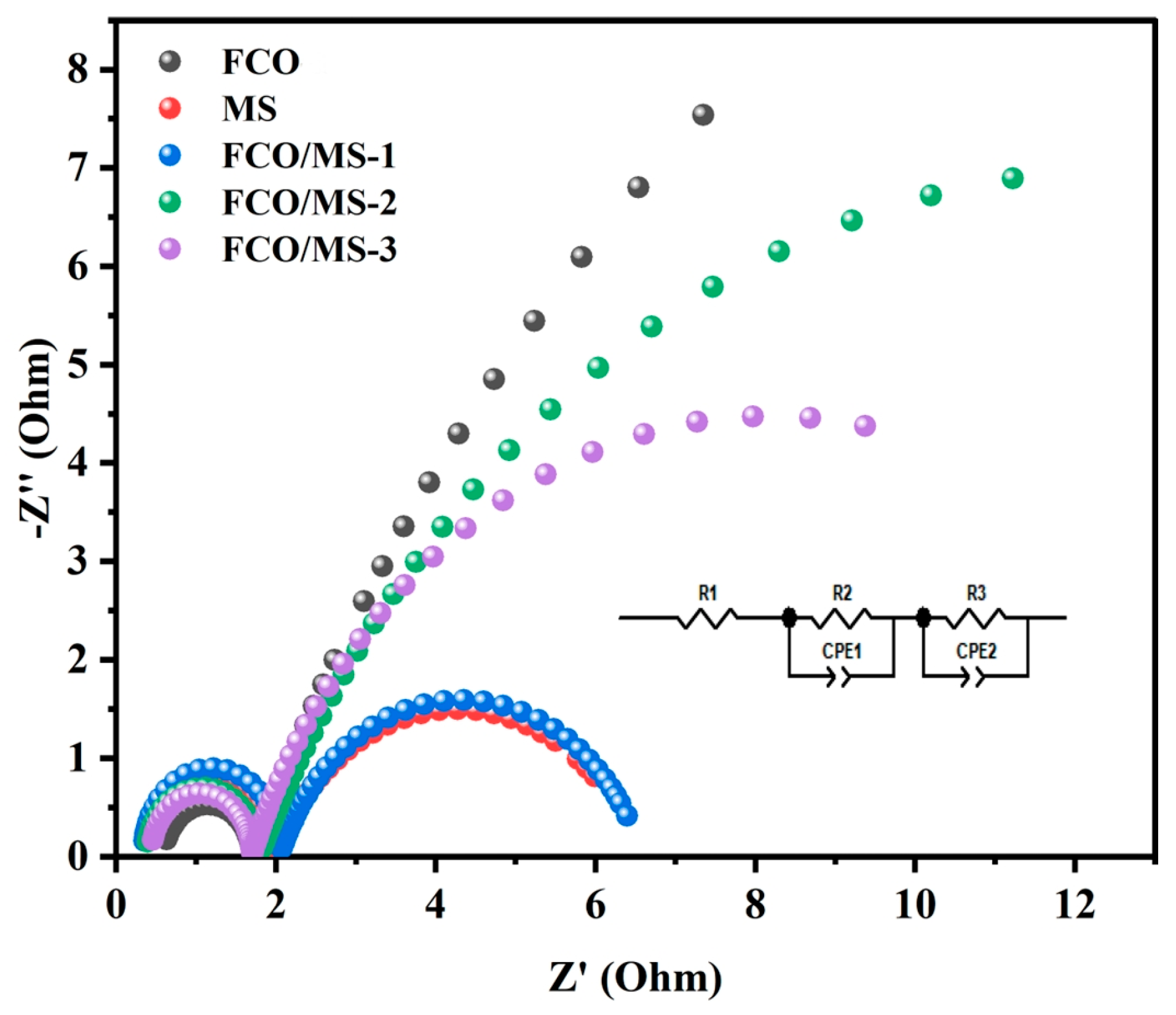
| Sample | Element | Resistance Value (Ω) | Error | Error % |
|---|---|---|---|---|
| FCO | Rs | 0.59 | 0.014 | 2.4 |
| Rsp | 1.1 | 0.018 | 1.7 | |
| Rct | 40 | 5.6 | 9.8 | |
| MS | Rs | 0.39 | 0.010 | 2.6 |
| Rsp | 1.6 | 0.020 | 1.2 | |
| Rct | 4.6 | 0.16 | 3.6 | |
| FCO/MS-1 | Rs | 0.34 | 0.0087 | 2.5 |
| Rsp | 1.7 | 0.019 | 1.1 | |
| Rct | 4.6 | 0.13 | 2.9 | |
| FCO/MS-2 | Rs | 0.37 | 0.011 | 3.0 |
| Rsp | 1.4 | 0.019 | 1.4 | |
| Rct | 22 | 1.5 | 6.8 | |
| FCO/MS-3 | Rs | 0.44 | 0.010 | 2.4 |
| Rsp | 1.3 | 0.015 | 1.2 | |
| Rct | 13 | 0.50 | 3.8 |
| Sample | Element | Resistance Value (Ω) | Error | Error % |
|---|---|---|---|---|
| FCO | Rs | 0.35 | 0.016 | 4.6 |
| Rsp | 1.2 | 0.019 | 1.6 | |
| Rct | 2.1 | 0.051 | 2.4 | |
| MS | Rs | 0.33 | 0.031 | 9.4 |
| Rsp | 1.4 | 0.047 | 3.4 | |
| Rct | 6.7 | 0.47 | 7.0 | |
| FCO/MS-1 | Rs | 0.18 | 0.0041 | 2.2 |
| Rsp | 1.3 | 0.012 | 1.0 | |
| Rct | 1.4 | 0.051 | 3.7 | |
| FCO/MS-2 | Rs | 0.33 | 0.016 | 4.8 |
| Rsp | 1.3 | 0.019 | 1.5 | |
| Rct | 2.0 | 0.049 | 2.4 | |
| FCO/MS-3 | Rs | 0.23 | 0.0064 | 2.8 |
| Rsp | 1.9 | 0.036 | 1.9 | |
| Rct | 1.3 | 0.0099 | 0.76 |
| Catalyst Name | Sample Number | Hydrothermal Temperature (°C) | Composite Ratio |
|---|---|---|---|
| FeCo2O4/MoS2 | FCO/MS-1 | 120 °C, 10 h/200 °C, 15 h | 1:0.3 |
| FCO/MS-2 | 1:0.7 | ||
| FCO/MS-3 | 1:1 |
Disclaimer/Publisher’s Note: The statements, opinions and data contained in all publications are solely those of the individual author(s) and contributor(s) and not of MDPI and/or the editor(s). MDPI and/or the editor(s) disclaim responsibility for any injury to people or property resulting from any ideas, methods, instructions or products referred to in the content. |
© 2024 by the authors. Licensee MDPI, Basel, Switzerland. This article is an open access article distributed under the terms and conditions of the Creative Commons Attribution (CC BY) license (https://creativecommons.org/licenses/by/4.0/).
Share and Cite
Chen, Z.; Li, Z.; Zhang, M.; Wang, Y.; Zhang, S.; Cheng, Y. Preparation of Non-Noble Metal Catalyst FeCo2O4/MoS2 for Production of Hydrogen and Oxygen by Electrochemical Decomposition of Water. Inorganics 2024, 12, 229. https://doi.org/10.3390/inorganics12080229
Chen Z, Li Z, Zhang M, Wang Y, Zhang S, Cheng Y. Preparation of Non-Noble Metal Catalyst FeCo2O4/MoS2 for Production of Hydrogen and Oxygen by Electrochemical Decomposition of Water. Inorganics. 2024; 12(8):229. https://doi.org/10.3390/inorganics12080229
Chicago/Turabian StyleChen, Zhouqian, Zongmei Li, Manyi Zhang, Yujia Wang, Siang Zhang, and Yuanyuan Cheng. 2024. "Preparation of Non-Noble Metal Catalyst FeCo2O4/MoS2 for Production of Hydrogen and Oxygen by Electrochemical Decomposition of Water" Inorganics 12, no. 8: 229. https://doi.org/10.3390/inorganics12080229
APA StyleChen, Z., Li, Z., Zhang, M., Wang, Y., Zhang, S., & Cheng, Y. (2024). Preparation of Non-Noble Metal Catalyst FeCo2O4/MoS2 for Production of Hydrogen and Oxygen by Electrochemical Decomposition of Water. Inorganics, 12(8), 229. https://doi.org/10.3390/inorganics12080229