
Progress, Applications, and Challenges of Amorphous Alloys: A Critical Review


Abstract
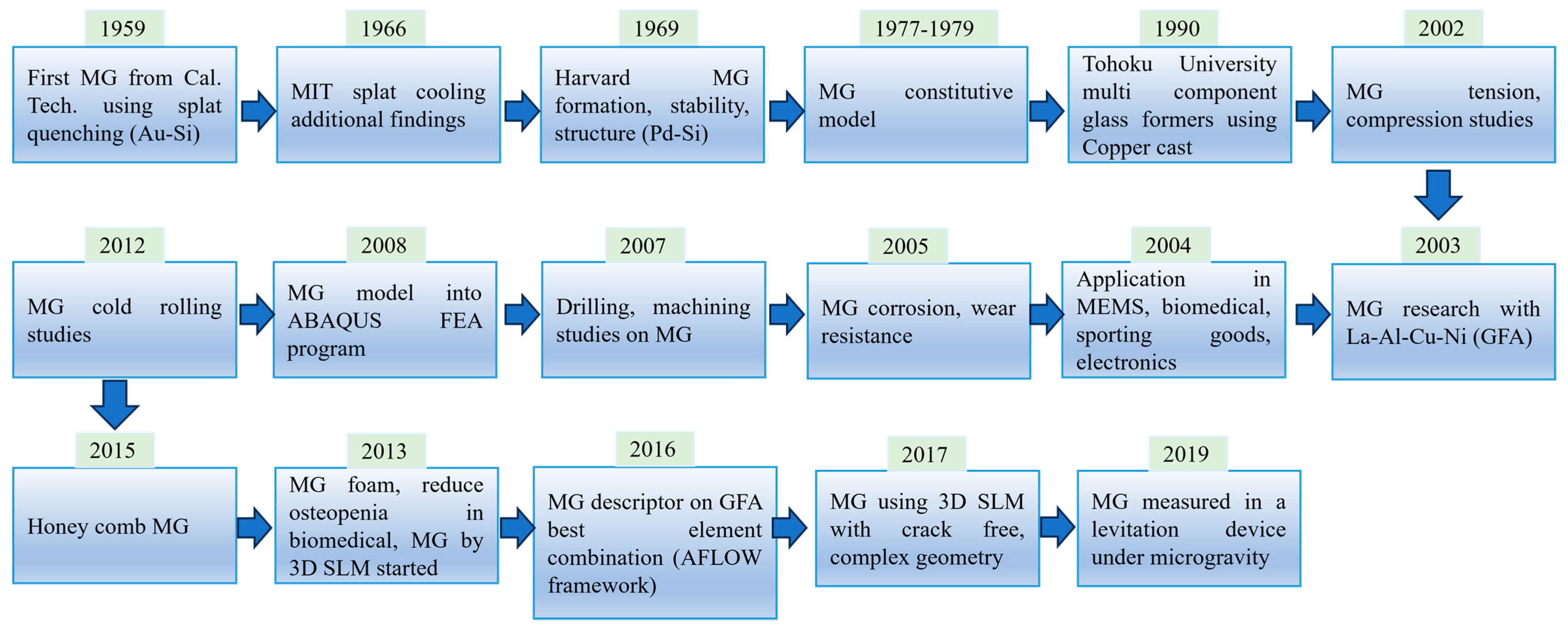
:1. Introduction
2. Formation and Production of Amorphous Alloys
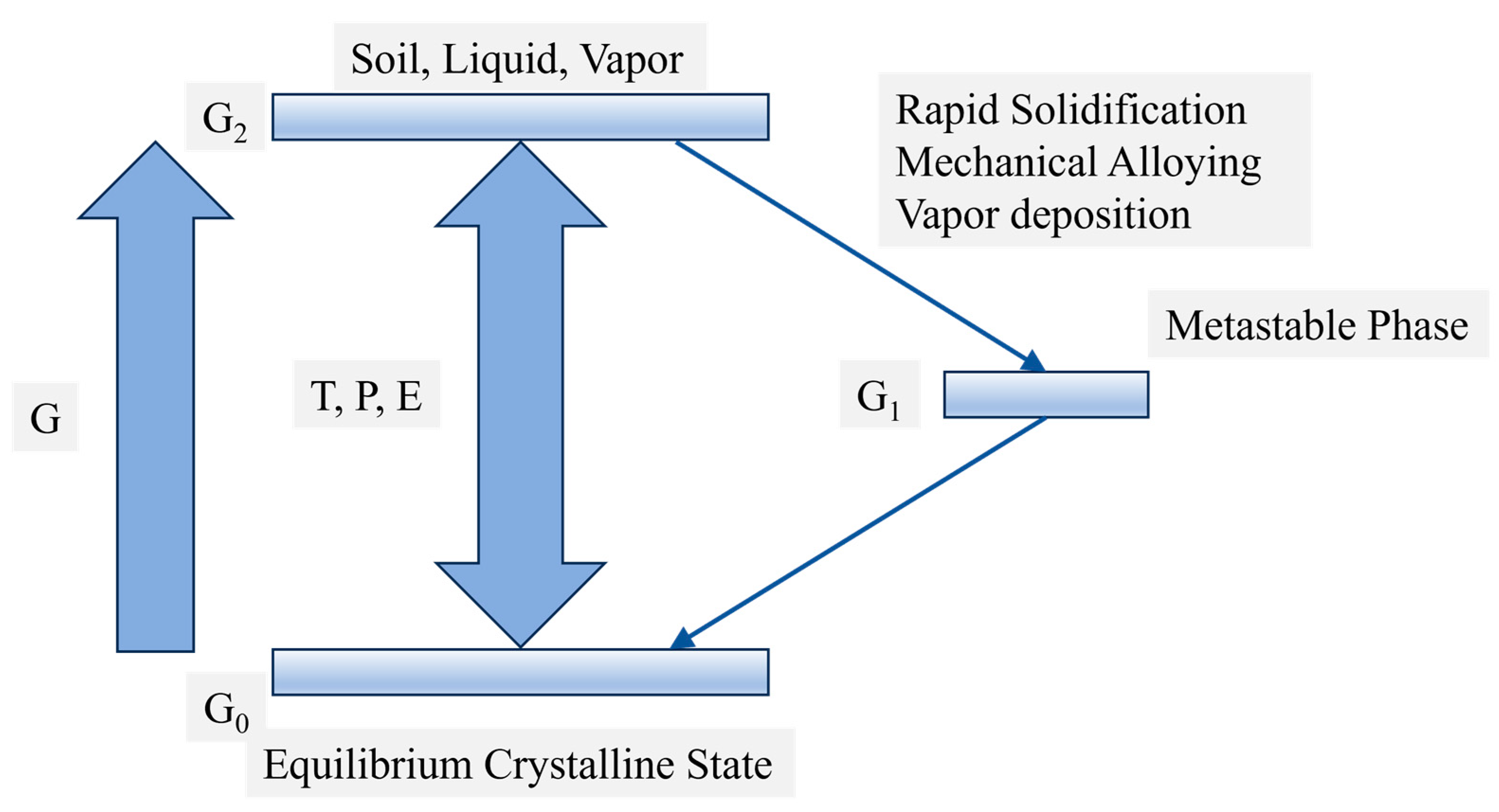
2.1. Conditions for the Formation of Amorphous Alloys
- Fundamental Principles of Amorphous Alloy Formation
- (1)
- Cooling Rate and Glass-Forming Ability (GFA)
- (2)
- Thermodynamic Conditions
- (3)
- Kinetic Factors
- b.
- Specific Conditions for Amorphous Alloy Formation
- (1)
- Chemical Bonding Characteristics
- (2)
- Atomic Size and Composition
- (3)
- Thermodynamic and Kinetic Stability
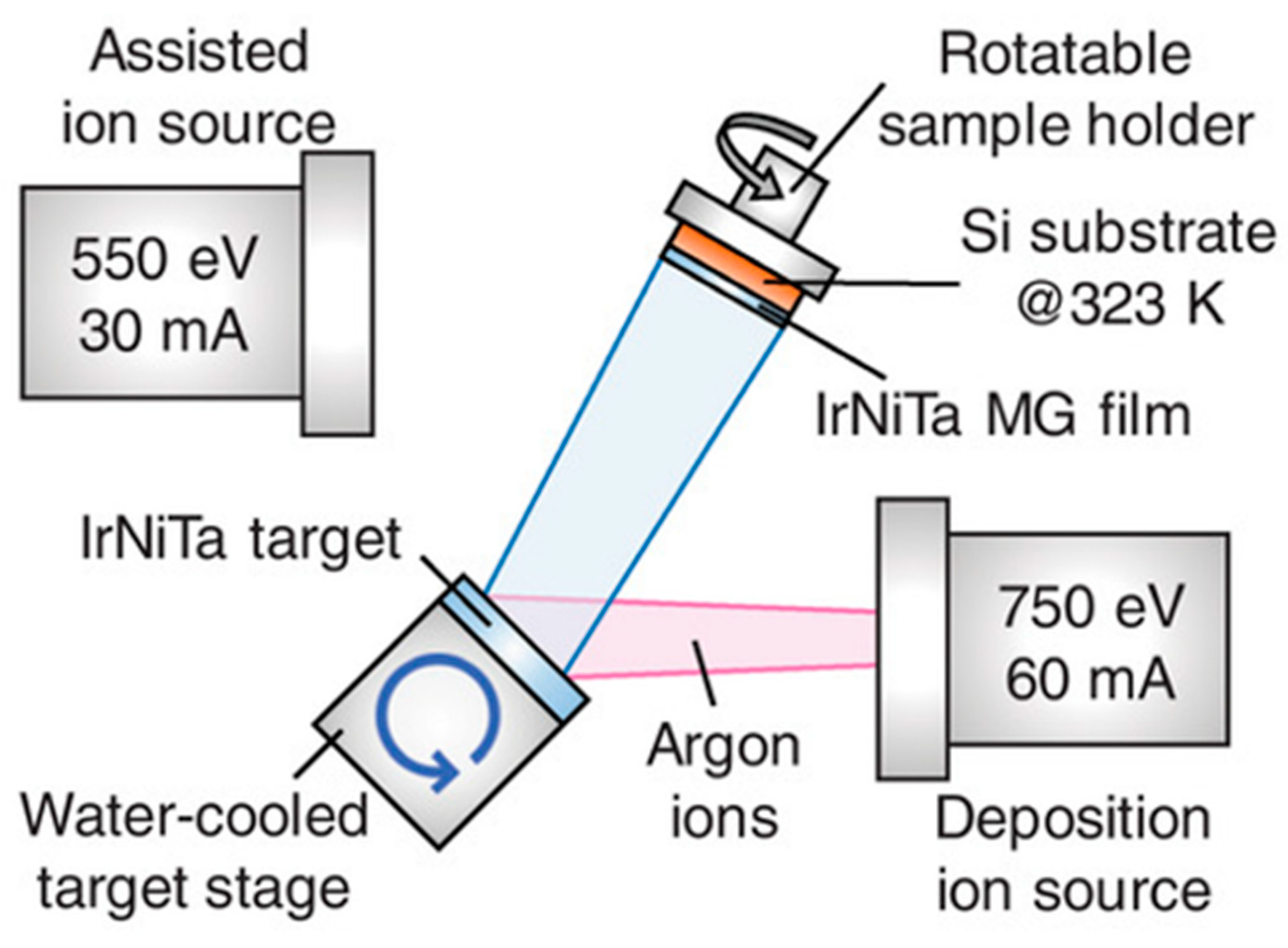
2.2. Rapid Solidification Techniques
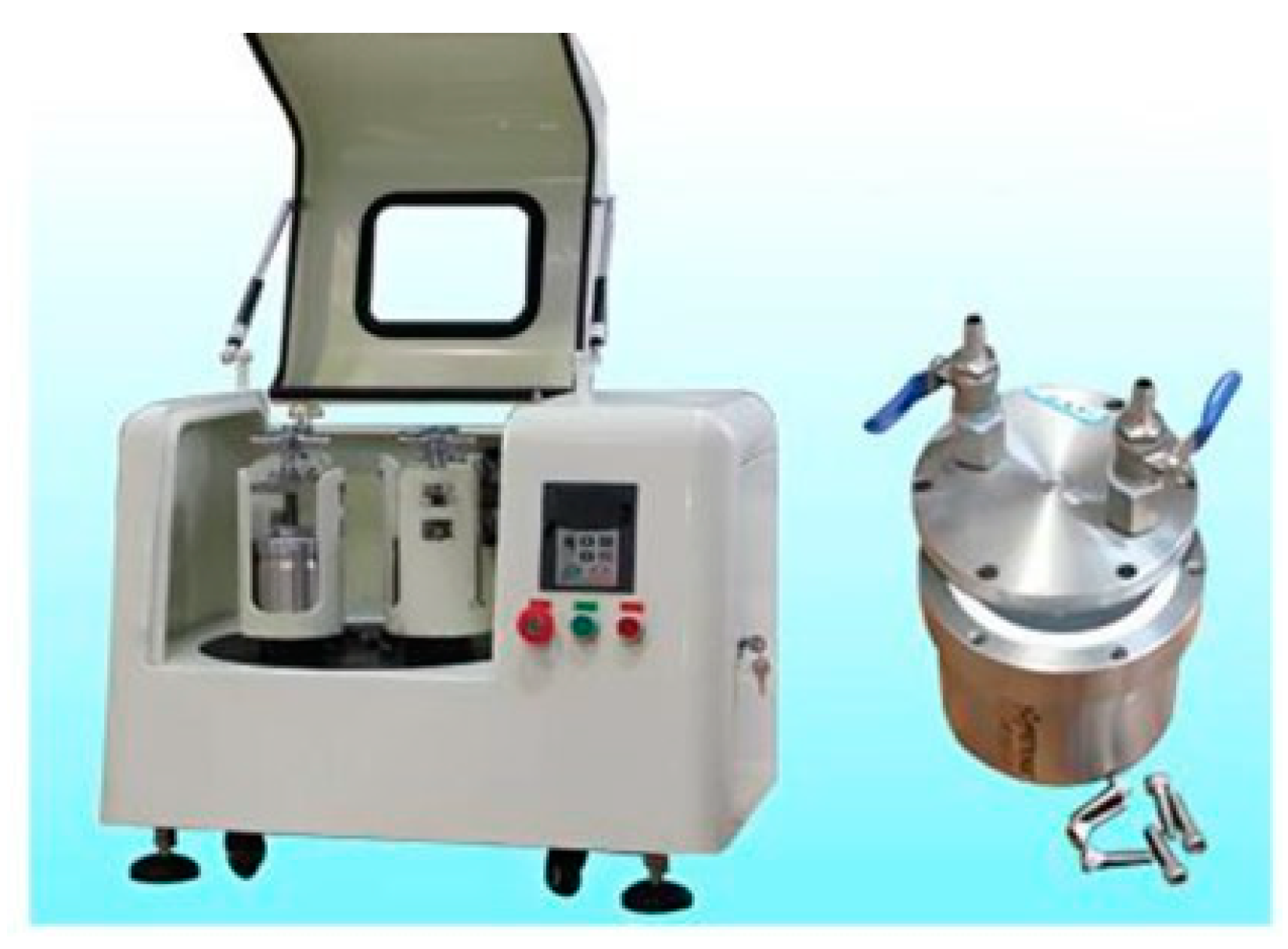
2.3. Other Production Methods
3. Structure and Properties
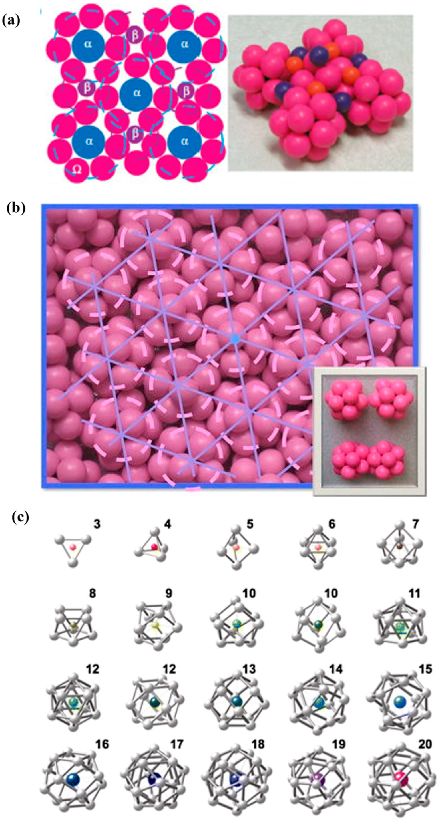
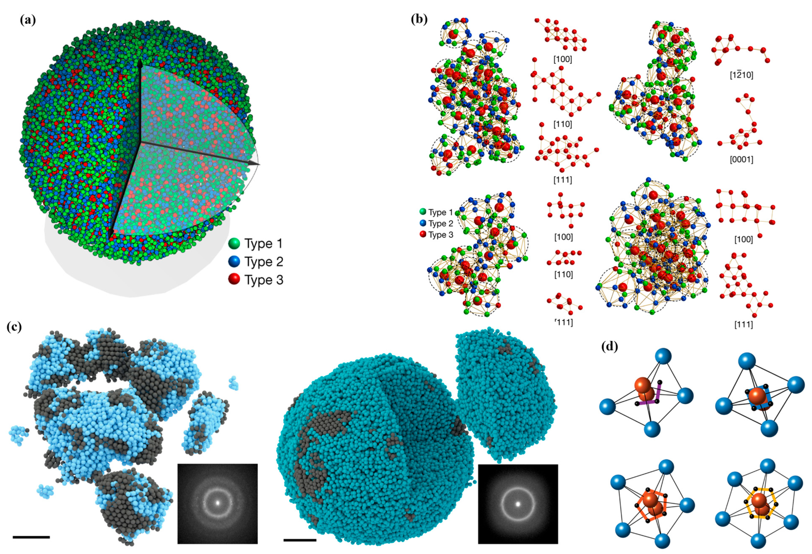
3.1. Description of the Atomic Structure of Amorphous Alloys
3.2. X-ray Diffraction and Transmission Electron Microscopy Analysis
4. Physical and Chemical Properties
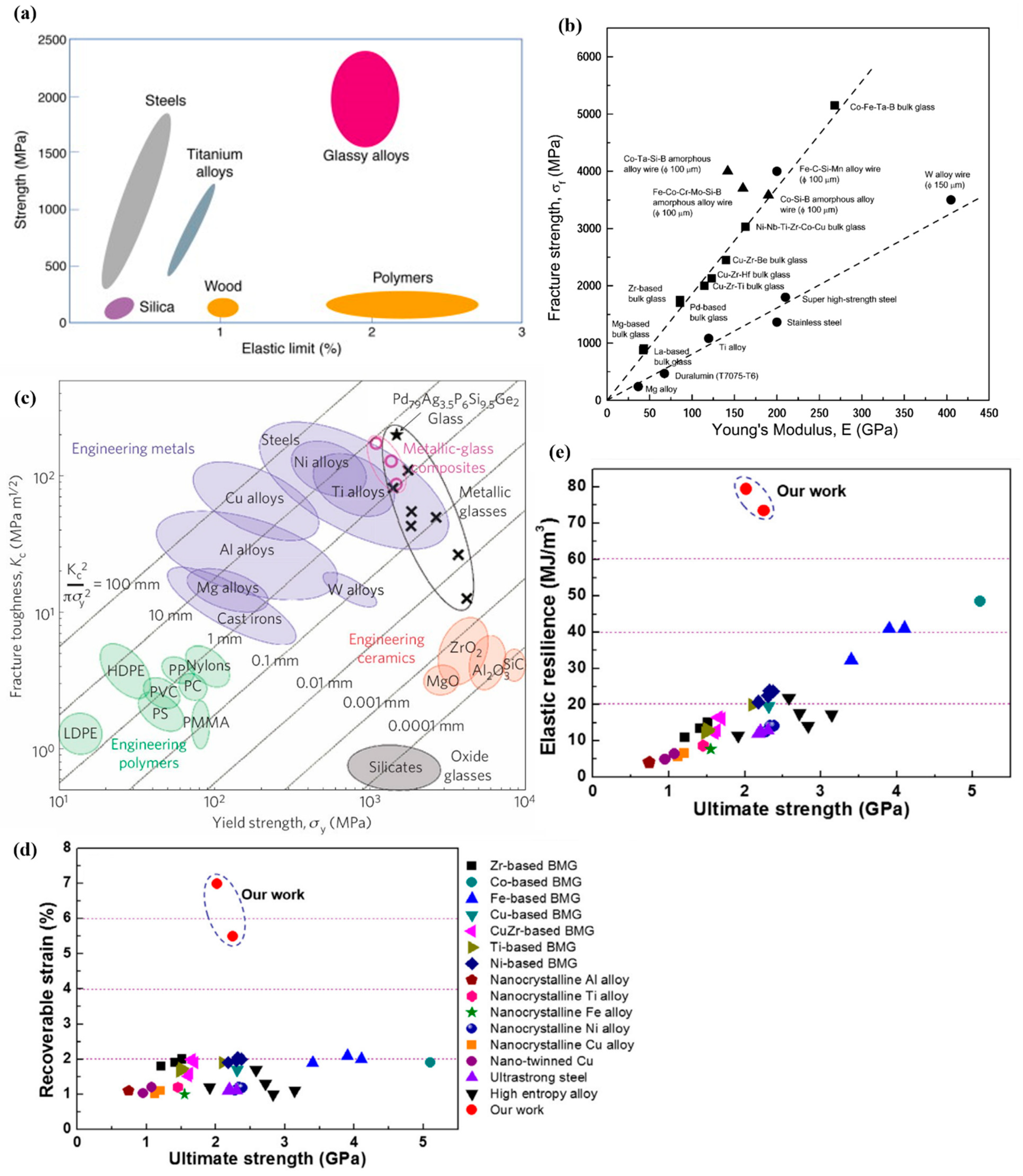
4.1. Mechanical Properties
4.2. Thermal Properties
4.3. Chemical Properties
5. Applications
5.1. Aerospace Industry
5.2. Biomedical Engineering
5.3. Electronics and Energy Technology
6. Challenges and Future Perspectives
6.1. Scalability and Cost Issues in the Production of Amorphous Alloys
6.2. Optimization of Crystallization Tendency and Thermal Stability
6.3. New Alloy Design and High-Throughput Screening Techniques
- Challenges in New Alloy Design
- b.
- Advantages of High-throughput Screening Technology
7. Conclusions
7.1. Summary of Research Achievements and Technological Advances in Amorphous Alloys
7.2. Future Research Directions and Technological Challenges
Funding
Conflicts of Interest
References
- Suryanarayana, C.; Inoue, A. Bulk Metallic Glasses; CRC press: Boca Raton, FL, USA, 2017. [Google Scholar]
- Axinte, E. Metallic glasses from “alchemy” to pure science: Present and future of design, processing and applications of glassy metals. Mater. Des. 2012, 35, 518–556. [Google Scholar] [CrossRef]
- Johnson, W.L. Thermodynamic and kinetic aspects of the crystal to glass transformation in metallic materials. Prog. Mater. Sci. 1986, 30, 81–134. [Google Scholar] [CrossRef]
- Sohrabi, S.; Fu, J.; Li, L.; Zhang, Y.; Li, X.; Sun, F.; Ma, J.; Wang, W.H. Manufacturing of metallic glass components: Processes, structures and properties. Prog. Mater. Sci. 2024, 144, 101283. [Google Scholar] [CrossRef]
- Hofmann, D.C. Bulk metallic glasses and their composites: A brief history of diverging fields. J. Mater. 2013, 2013, 517904. [Google Scholar] [CrossRef]
- Klement, W.; Willens, R.H.; Duwez, P.O.L. Non-crystalline structure in solidified gold–silicon alloys. Nature 1960, 187, 869–870. [Google Scholar] [CrossRef]
- Herzer, G. Modern soft magnets: Amorphous and nanocrystalline materials. Acta Mater. 2013, 61, 718–734. [Google Scholar] [CrossRef]
- Inoue, A. Bulk amorphous alloys with soft and hard magnetic properties. Mater. Sci. Eng. A 1997, 226, 357–363. [Google Scholar] [CrossRef]
- Kui, H.W.; Greer, A.L.; Turnbull, D. Formation of bulk metallic glass by fluxing. Appl. Phys. Lett. 1984, 45, 615–616. [Google Scholar] [CrossRef]
- Peker, A.; Johnson, W.L. A highly processable metallic glass: Zr41. 2Ti13. 8Cu12. 5Ni10. 0Be22. 5. Appl. Phys. Lett. 1993, 63, 2342–2344. [Google Scholar] [CrossRef]
- Zhang, B.; Zhao, D.Q.; Pan, M.X.; Wang, W.H.; Greer, A.L. Amorphous metallic plastic. Phys. Rev. Lett. 2005, 94, 205502. [Google Scholar] [CrossRef]
- Bardt, J.A.; Bourne, G.R.; Schmitz, T.L.; Ziegert, J.C.; Gregory Sawyer, W. Micromolding three-dimensional amorphous metal structures. J. Mater. Res. 2007, 22, 339–343. [Google Scholar] [CrossRef]
- Kumar, G.; Tang, H.X.; Schroers, J. Nanomoulding with amorphous metals. Nature 2009, 457, 868–872. [Google Scholar] [CrossRef]
- Greer, A.L.; Ma, E. Bulk metallic glasses: At the cutting edge of metals research. MRS Bull. 2007, 32, 611–619. [Google Scholar] [CrossRef]
- Halim, Q.; Mohamed, N.A.N.; Rejab, M.R.M.; Naim, W.N.W.A.; Ma, Q. Metallic glass properties, processing method and development perspective: A review. Int. J. Adv. Manuf. Technol. 2021, 112, 1231–1258. [Google Scholar] [CrossRef]
- Fukushige, T.; Hata, S.; Shimokohbe, A. A MEMS conical spring actuator array. J. Microelectromechanical Syst. 2005, 14, 243–253. [Google Scholar] [CrossRef]
- Schroers, J. Processing of bulk metallic glass. Adv. Mater. 2010, 22, 1566–1597. [Google Scholar] [CrossRef] [PubMed]
- Peng, X.; Han, J.; Wang, Y.; Bo, Z.; Nie, A.; Li, P.; Li, Y.; Wu, H.; Liu, P.; Lu, Z.; et al. Unexpected enhanced catalytic performance via highly dense interfaces in ultra-fine amorphous-nanocrystalline biphasic structure. Appl. Mater. Today 2022, 29, 101689. [Google Scholar] [CrossRef]
- Telford, M. The case for bulk metallic glass. Mater. Today 2004, 7, 36–43. [Google Scholar] [CrossRef]
- Gao, K.; Zhu, X.G.; Chen, L.; Li, W.H.; Xu, X.; Pan, B.T.; Li, W.R.; Zhou, W.H.; Li, L.; Huang, W.; et al. Recent development in the application of bulk metallic glasses. J. Mater. Sci. Technol. 2022, 131, 115–121. [Google Scholar] [CrossRef]
- Miracle, D.B. A physical model for metallic glass structures: An introduction and update. Jom 2012, 64, 846–855. [Google Scholar] [CrossRef]
- Wang, P.F.; Jiang, H.Y.; Shi, J.A.; Liu, M.; Gu, L.; Zhou, W.; Orava, J.; Sun, Y.H.; Wang, W.H.; Bai, H.Y. Regulated color-changing metallic glasses. J. Alloys Compd. 2021, 876, 160139. [Google Scholar] [CrossRef]
- Lee, S.; Kim, S.W.; Ghidelli, M.; An, H.S.; Jang, J.; Bassi, A.L.; Li, S.Y.; Park, J.U. Integration of transparent supercapacitors and electrodes using nanostructured metallic glass films for wirelessly rechargeable, skin heat patches. Nano Lett. 2020, 20, 4872–4881. [Google Scholar] [CrossRef] [PubMed]
- Yan, W.; Richard, I.; Kurtuldu, G.; James, N.D.; Schiavone, G.; Squair, J.W.; Nguyen-Dang, T.; Das Gupta, T.; Qu, Y.; Cao, J.D.; et al. Structured nanoscale metallic glass fibres with extreme aspect ratios. Nat. Nanotechnol. 2020, 15, 875–882. [Google Scholar] [CrossRef]
- Lin, X.H.; Johnson, W.L. Formation of Ti–Zr–Cu–Ni bulk metallic glasses. J. Appl. Phys. 1995, 78, 6514–6519. [Google Scholar] [CrossRef]
- Wang, W.H.; Dong, C.; Shek, C.H. Bulk metallic glasses. Mater. Sci. Eng. R Rep. 2004, 44, 45–89. [Google Scholar] [CrossRef]
- Wang, W.H. The elastic properties, elastic models and elastic perspectives of metallic glasses. Prog. Mater. Sci. 2012, 57, 487–656. [Google Scholar] [CrossRef]
- Schroers, J. Bulk metallic glasses. Phys. Today 2013, 66, 32–37. [Google Scholar] [CrossRef]
- Chen, H.S.; Miller, C.E. A rapid quenching technique for the preparation of thin uniform films of amorphous solids. Rev. Sci. Instrum. 1970, 41, 1237–1238. [Google Scholar] [CrossRef]
- Turnbull, D. Kinetics of solidification of supercooled liquid mercury droplets. J. Chem. Phys. 1952, 20, 411–424. [Google Scholar] [CrossRef]
- Becker, R.; Döring, W. Kinetische behandlung der keimbildung in übersättigten dämpfen. Ann. Phys. 1935, 416, 719–752. [Google Scholar] [CrossRef]
- Dyre, J.C. Colloquium: The glass transition and elastic models of glass-forming liquids. Rev. Mod. Phys. 2006, 78, 953. [Google Scholar] [CrossRef]
- Egami, T.; Waseda, Y. Atomic size effect on the formability of metallic glasses. J. Non-Cryst. Solids 1984, 64, 113–134. [Google Scholar] [CrossRef]
- Suryanarayana, C. Non-Equilibrium Processing of Materials; Elsevier: Amsterdam, The Netherlands, 1999. [Google Scholar]
- Zhao, R.; Jiang, H.Y.; Luo, P.; Sun, Y.T.; Li, Z.A.; Wu, W.W.; Shen, L.Q.; Liu, M.; Zhao, S.F.; Wen, P.; et al. A facile strategy to produce monatomic tantalum metallic glass. Appl. Phys. Lett. 2020, 117, 131903. [Google Scholar] [CrossRef]
- Zhong, L.; Wang, J.; Sheng, H.; Zhang, Z.; Mao, S.X. Formation of monatomic metallic glasses through ultrafast liquid quenching. Nature 2014, 512, 177–180. [Google Scholar] [CrossRef] [PubMed]
- Wang, Z.J.; Li, M.X.; Yu, J.H.; Ge, X.B.; Liu, Y.H.; Wang, W.H. Low-iridium-content IrNiTa metallic glass films as intrinsically active catalysts for hydrogen evolution reaction. Adv. Mater. 2020, 32, 1906384. [Google Scholar] [CrossRef]
- Jacobson, L.A.; McKittrick, J. Rapid solidification processing. Mater. Sci. Eng. R Rep. 1994, 11, 355–408. [Google Scholar] [CrossRef]
- Soare, V.; Burada, M.; Constantin, I.; Mitrică, D.; Bădiliţă, V.; Caragea, A.; Târcolea, M. Electrochemical deposition and microstructural characterization of AlCrFeMnNi and AlCrCuFeMnNi high entropy alloy thin films. Appl. Surf. Sci. 2015, 358, 533–539. [Google Scholar] [CrossRef]
- Greer, A.L. Metallic glasses. Science 1995, 267, 1947–1953. [Google Scholar] [CrossRef]
- Liebermann, H.H. The dependence of the geometry of glassy alloy ribbons on the chill block melt-spinning process parameters. Mater. Sci. Eng. 1980, 43, 203–210. [Google Scholar] [CrossRef]
- Drehman, A.J.; Greer, A.L.; Turnbull, D. Bulk formation of a metallic glass: Pd40Ni40P20. Appl. Phys. Lett. 1982, 41, 716–717. [Google Scholar] [CrossRef]
- Brenner, A. Electrodeposition of Alloys: Principles and Practice; Elsevier: Amsterdam, The Netherlands, 2013. [Google Scholar]
- Brenner, A.; Couch, D.E.; Williams, E.K. Electrodeposition of alloys of phosphorus with nickel or cobalt. J. Res. Nat. Bur. Stand 1950, 44, 109. [Google Scholar] [CrossRef]
- Mukhopadhyay, A.; Jangid, M.K. Li metal battery, heal thyself. Science 2018, 359, 1463. [Google Scholar] [CrossRef] [PubMed]
- Liu, D.H.; Bai, Z.; Li, M.; Yu, A.; Luo, D.; Liu, W.; Yang, L.; Lu, J.; Amine, K.; Chen, Z. Developing high safety Li-metal anodes for future high-energy Li-metal batteries: Strategies and perspectives. Chem. Soc. Rev. 2020, 49, 5407–5445. [Google Scholar] [CrossRef] [PubMed]
- Pedraza, D.F. Irradiation as a tool for studying solid-state amorphization phenomena. Metall. Trans. A 1990, 21, 1809–1815. [Google Scholar] [CrossRef]
- Li, S.; Pastewka, L.; Gumbsch, P. Glass formation by severe plastic deformation of crystalline Cu| Zr nano-layers. Acta Mater. 2019, 165, 577–586. [Google Scholar] [CrossRef]
- Saito, Y.; Tsuji, N.; Utsunomiya, H.; Sakai, T.; Hong, R.G. Ultra-fine grained bulk aluminum produced by accumulative roll-bonding (ARB) process. Scr. Mater. 1998, 39, 1221–1227. [Google Scholar] [CrossRef]
- Suryanarayana, C. Mechanical alloying and milling. Prog. Mater. Sci. 2001, 46, 1–184. [Google Scholar] [CrossRef]
- Jang, D.; Greer, J.R. Transition from a strong-yet-brittle to a stronger-and-ductile state by size reduction of metallic glasses. Nat. Mater. 2010, 9, 215–219. [Google Scholar] [CrossRef]
- Greer, J.R.; De Hosson, J.T.M. Plasticity in small-sized metallic systems: Intrinsic versus extrinsic size effect. Prog. Mater. Sci. 2011, 56, 654–724. [Google Scholar] [CrossRef]
- Bignoli, F.; Djemia, P.; Terraneo, G.; Abadias, G.; Gammer, C.; Lassnig, A.; Teixeira, C.A.; Lee, S.; Ahmadian, A.; Bassi, A.L.; et al. Novel class of crystal/glass ultrafine nanolaminates with large and tunable mechanical properties. ACS Appl. Mater. Interfaces 2024, 16, 35686–35696. [Google Scholar] [CrossRef]
- Chu, J.P.; Jang, J.S.C.; Huang, J.C.; Chou, H.S.; Yang, Y.; Ye, J.C.; Wang, Y.C.; Lee, J.W.; Liu, F.X.; Liaw, P.K.; et al. Thin film metallic glasses: Unique properties and potential applications. Thin Solid Film. 2012, 520, 5097–5122. [Google Scholar] [CrossRef]
- Tory, E.M.; Church, B.H.; Tam, M.K.; Ratner, M. Simulated random packing of equal spheres. Can. J. Chem. Eng. 1973, 51, 484–493. [Google Scholar] [CrossRef]
- Kauzmann, W. The nature of the glassy state and the behavior of liquids at low temperatures. Chem. Rev. 1948, 43, 219–256. [Google Scholar] [CrossRef]
- Miracle, D.B. A structural model for metallic glasses. Nat. Mater. 2004, 3, 697–702. [Google Scholar] [CrossRef] [PubMed]
- Miracle, D.B.; Lord, E.A.; Ranganathan, S. Candidate atomic cluster configurations in metallic glass structures. Mater. Trans. 2006, 47, 1737–1742. [Google Scholar] [CrossRef]
- Miracle, D.B.; Sanders, W.S.; Senkov, O.N. The influence of efficient atomic packing on the constitution of metallic glasses. Philos. Mag. 2003, 83, 2409–2428. [Google Scholar] [CrossRef]
- Miracle, D.B. The efficient cluster packing model–An atomic structural model for metallic glasses. Acta Mater. 2006, 54, 4317–4336. [Google Scholar] [CrossRef]
- Miracle, D.B.; Egami, T.; Flores, K.M.; Kelton, K.F. Structural aspects of metallic glasses. Mrs Bull. 2007, 32, 629–634. [Google Scholar] [CrossRef]
- Miracle, D.B.; Louzguine-Luzgin, D.V.; Louzguina-Luzgina, L.V.; Inoue, A. An assessment of binary metallic glasses: Correlations between structure, glass forming ability and stability. Int. Mater. Rev. 2010, 55, 218–256. [Google Scholar] [CrossRef]
- Cheng, Y.Q.; Ma, E. Atomic-level structure and structure–property relationship in metallic glasses. Prog. Mater. Sci. 2011, 56, 379–473. [Google Scholar] [CrossRef]
- Li, M.X.; Zhao, S.F.; Lu, Z.; Hirata, A.; Wen, P.; Bai, H.Y.; Chen, M.; Schroers, J.; Liu, Y.; Wang, W.-H. High-temperature bulk metallic glasses developed by combinatorial methods. Nature 2019, 569, 99–103. [Google Scholar] [CrossRef] [PubMed]
- Hu, L.; Bian, X.; Wang, W.; Zhang, J.; Jia, Y. Liquid fragility and characteristic of the structure corresponding to the prepeak of AlNiCe amorphous alloys. Acta Mater. 2004, 52, 4773–4781. [Google Scholar] [CrossRef]
- Lee, G.W.; Gangopadhyay, A.K.; Hyers, R.W.; Rathz, T.J.; Rogers, J.R.; Robinson, D.S.; Goldman, A.I.; Kelton, K.F. Local structure of equilibrium and supercooled Ti-Zr-Ni liquids. Phys. Rev. B 2008, 77, 184102. [Google Scholar] [CrossRef]
- Doye, J.P.; Miller, M.A.; Wales, D.J. Evolution of the potential energy surface with size for Lennard-Jones clusters. J. Chem. Phys. 1999, 111, 8417–8428. [Google Scholar] [CrossRef]
- Yin, H.; Huang, Y.; Daisenberg, D.; Xue, P.; Jiang, S.; Ru, W.; Jiang, S.; Bao, Y.; Bian, X.; Tong, X.; et al. Atomic structure evolution of high entropy metallic glass microwires at cryogenic temperature. Scr. Mater. 2019, 163, 29–33. [Google Scholar] [CrossRef]
- Fujita, T.; Konno, K.; Zhang, W.; Kumar, V.; Matsuura, M.; Inoue, A.; Sakurai, T.; Chen, M.W. Atomic-Scale Heterogeneity of a Multicomponent Bulk Metallic Glass with Excellent Glass Forming Ability. Phys. Rev. Lett. 2009, 103, 075502. [Google Scholar] [CrossRef]
- Wochner, P.; Gutt, C.; Autenrieth, T.; Demmer, T.; Bugaev, V.; Ortiz, A.D.; Duri, A.; Zontone, F.; Grübel, G.; Dosch, H. X-ray cross correlation analysis uncovers hidden local symmetries in disordered matter. Proc. Natl. Acad. Sci. USA 2009, 106, 11511–11514. [Google Scholar] [CrossRef]
- Billinge, S.J.; Levin, I. The problem with determining atomic structure at the nanoscale. Science 2007, 316, 561–565. [Google Scholar] [CrossRef]
- Tian, L.; Volkert, C.A. Measuring structural heterogeneities in metallic glasses using transmission electron microscopy. Metals 2018, 8, 1085. [Google Scholar] [CrossRef]
- Su, Z.; Decencière, E.; Nguyen, T.T.; El-Amiry, K.; De Andrade, V.; Franco, A.A.; Demortière, A. Artificial neural network approach for multiphase segmentation of battery electrode nano-CT images. npj Comput. Mater. 2022, 8, 30. [Google Scholar] [CrossRef]
- Stoica, M.; Sarac, B.; Spieckermann, F.; Wright, J.; Gammer, C.; Han, J.; Gostin, P.F.; Eckert, J.; Löffler, J.F. X-ray Diffraction Computed Nanotomography Applied to Solve the Structure of Hierarchically Phase-Separated Metallic Glass. ACS Nano 2021, 15, 2386–2398. [Google Scholar] [CrossRef]
- Huang, B.; Ge, T.P.; Liu, G.L.; Luan, J.H.; He, Q.F.; Yuan, Q.X.; Huang, W.X.; Zhang, K.; Bai, H.Y.; Shek, C.H.; et al. Density fluctuations with fractal order in metallic glasses detected by synchrotron X-ray nano-computed tomography. Acta Mater. 2018, 155, 69–79. [Google Scholar] [CrossRef]
- Cao, K.; Skowron, S.T.; Biskupek, J.; Stoppiello, C.T.; Leist, C.; Besley, E.; Khlobystov, A.N.; Kaiser, U. Imaging an unsupported metal–metal bond in dirhenium molecules at the atomic scale. Sci. Adv. 2020, 6, eaay5849. [Google Scholar] [CrossRef]
- Liu, C.; Cui, J.; Cheng, Z.; Zhang, B.; Zhang, S.; Ding, J.; Yu, R.; Ma, E. Direct Observation of Oxygen Atoms Taking Tetrahedral Interstitial Sites in Medium-Entropy Body-Centered-Cubic Solutions. Adv. Mater. 2023, 35, 2209941. [Google Scholar] [CrossRef] [PubMed]
- Hirata, A.; Hirotsu, Y.; Ohkubo, T.; Tanaka, N.; Nieh, T.G. Local atomic structure of Pd–Ni–P bulk metallic glass examined by high-resolution electron microscopy and electron diffraction. Intermetallics 2006, 14, 903–907. [Google Scholar] [CrossRef]
- Zhu, F.; Hirata, A.; Liu, P.; Song, S.; Tian, Y.; Han, J.; Fujita, T.; Chen, M. Correlation between local structure order and spatial heterogeneity in a metallic glass. Phys. Rev. Lett. 2017, 119, 215501. [Google Scholar] [CrossRef] [PubMed]
- Lau, M.T.; Lan, S.; Yip, Y.L.; Kui, H.W. A metastable liquid state miscibility gap in undercooled Pd–Ni–P melts. J. Non-Cryst. Solids 2012, 358, 2667–2673. [Google Scholar] [CrossRef]
- Hirata, A.; Kang, L.J.; Fujita, T.; Klumov, B.; Matsue, K.; Kotani, M.; Yavari, A.R.; Chen, M.W. Geometric frustration of icosahedron in metallic glasses. Science 2013, 341, 376–379. [Google Scholar] [CrossRef]
- Hirata, A.; Guan, P.; Fujita, T.; Hirotsu, Y.; Inoue, A.; Yavari, A.R.; Sakurai, T.; Chen, M. Direct observation of local atomic order in a metallic glass. Nat. Mater. 2011, 10, 28–33. [Google Scholar] [CrossRef]
- Miao, J.; Ercius, P.; Billinge, S.J. Atomic electron tomography: 3D structures without crystals. Science 2016, 353, aaf2157. [Google Scholar] [CrossRef]
- Yang, Y.; Zhou, J.; Zhu, F.; Yuan, Y.; Chang, D.J.; Kim, D.S.; Pham, M.; Rana, A.; Tian, X.; Yao, Y.; et al. Determining the three-dimensional atomic structure of an amorphous solid. Nature 2021, 592, 60–64. [Google Scholar] [CrossRef]
- Yuan, Y.; Kim, D.S.; Zhou, J.; Chang, D.J.; Zhu, F.; Nagaoka, Y.; Yang, Y.; Pham, M.; Osher, S.J.; Chen, O.; et al. Three-dimensional atomic packing in amorphous solids with liquid-like structure. Nat. Mater. 2022, 21, 95–102. [Google Scholar] [CrossRef] [PubMed]
- Inoue, A.; Shen, B.L.; Koshiba, H.; Kato, H.; Yavari, A.R. Ultra-high strength above 5000 MPa and soft magnetic properties of Co–Fe–Ta–B bulk glassy alloys. Acta Mater. 2004, 52, 1631–1637. [Google Scholar] [CrossRef]
- Demetriou, M.D.; Launey, M.E.; Garrett, G.; Schramm, J.P.; Hofmann, D.C.; Johnson, W.L.; Ritchie, R.O. A damage-tolerant glass. Nat. Mater. 2011, 10, 123–128. [Google Scholar] [CrossRef]
- Zhang, J.; Liu, Y.; Yang, H.; Ren, Y.; Cui, L.; Jiang, D.; Wu, Z.; Ma, Z.; Guo, F.; Bakhtiari, S.; et al. Achieving 5.9% elastic strain in kilograms of metallic glasses: Nanoscopic strain engineering goes macro. Mater. Today 2020, 37, 18–26. [Google Scholar] [CrossRef]
- Sun, Y.; Zhang, H.F.; Fu, H.M.; Wang, A.M.; Hu, Z.Q. Mg–Cu–Ag–Er bulk metallic glasses with high glass forming ability and compressive strength. Mater. Sci. Eng. A 2009, 502, 148–152. [Google Scholar] [CrossRef]
- Gong, P.; Wang, X.; Shao, Y.; Chen, N.; Liu, X.; Yao, K.F. A Ti–Zr–Be–Fe–Cu bulk metallic glass with superior glass-forming ability and high specific strength. Intermetallics 2013, 43, 177–181. [Google Scholar] [CrossRef]
- Tan, J.; Pan, F.S.; Zhang, Y.; Sun, B.A.; He, J.; Zheng, N.; Stoica, M.; Kühn, U.; Eckert, J. Formation of Zr–Co–Al bulk metallic glasses with high strength and large plasticity. Intermetallics 2012, 31, 282–286. [Google Scholar] [CrossRef]
- Liu, Y.H.; Wang, G.; Pan, M.X.; Yu, P.; Zhao, D.Q.; Wang, W.H. Deformation behaviors and mechanism of Ni–Co–Nb–Ta bulk metallic glasses with high strength and plasticity. J. Mater. Res. 2007, 22, 869–875. [Google Scholar] [CrossRef]
- Wang, J.; Cao, W.; Wang, L.; Zhu, S.; Guan, S.; Huang, L.; Li, R.; Zhang, T. Fe–Al–P–C–B bulk metallic glass with good mechanical and soft magnetic properties. J. Alloys Compd. 2015, 637, 5–9. [Google Scholar] [CrossRef]
- Inoue, A.; Shen, B.L.; Chang, C.T. Fe-and Co-based bulk glassy alloys with ultrahigh strength of over 4000 MPa. Intermetallics 2006, 14, 936–944. [Google Scholar] [CrossRef]
- Xi, X.K.; Zhao, D.Q.; Pan, M.X.; Wang, W.H.; Wu, Y.; Lewandowski, J.J. Fracture of brittle metallic glasses: Brittleness or plasticity. Phys. Rev. Lett. 2005, 94, 125510. [Google Scholar] [CrossRef] [PubMed]
- Gilbert, C.J.; Schroeder, V.; Ritchie, R.O. Mechanisms for fracture and fatigue-crack propagation in a bulk metallic glass. Metall. Mater. Trans. A 1999, 30, 1739–1753. [Google Scholar] [CrossRef]
- Inoue, A. High strength bulk amorphous alloys with low critical cooling rates (overview). Materials Transactions. JIM 1995, 36, 866–875. [Google Scholar]
- Révész, Á.; Kis-Tóth, Á.; Varga, L.K.; Schafler, E.; Bakonyi, I.; Spassov, T. Hydrogen storage of melt-spun amorphous Mg65Ni20Cu5Y10 alloy deformed by high-pressure torsion. Int. J. Hydrog. Energy 2012, 37, 5769–5776. [Google Scholar] [CrossRef]
- Lang, X.Y.; Guo, H.; Chen, L.Y.; Kudo, A.; Yu, J.S.; Zhang, W.; Inoue, A.; Chen, M.W. Novel nanoporous Au− Pd alloy with high catalytic activity and excellent electrochemical stability. J. Phys. Chem. C 2010, 114, 2600–2603. [Google Scholar] [CrossRef]
- Cao, J.D.; Kirkland, N.T.; Laws, K.J.; Birbilis, N.; Ferry, M. Ca–Mg–Zn bulk metallic glasses as bioresorbable metals. Acta Biomater. 2012, 8, 2375–2383. [Google Scholar] [CrossRef] [PubMed]
- Guo, S.F.; Zhang, H.J.; Liu, Z.; Chen, W.; Xie, S.F. Corrosion resistances of amorphous and crystalline Zr-based alloys in simulated seawater. Electrochem. Commun. 2012, 24, 39–42. [Google Scholar] [CrossRef]
- Grimberg, A.; Baur, H.; Bochsler, P.; Bühler, F.; Burnett, D.S.; Hays, C.C.; Heber, V.S.; Jurewicz, A.J.G.; Wieler, R. Solar wind neon from Genesis: Implications for the lunar noble gas record. Science 2006, 314, 1133–1135. [Google Scholar] [CrossRef]
- Inoue, A. New Functional Materials, Fundamentals of Metallic Glasses and Their Applications to Industry; Technos Co.: Toyokawa-shi, Japan, 2009; ISBN 978-4-914728-58-5. [Google Scholar]


Disclaimer/Publisher’s Note: The statements, opinions and data contained in all publications are solely those of the individual author(s) and contributor(s) and not of MDPI and/or the editor(s). MDPI and/or the editor(s) disclaim responsibility for any injury to people or property resulting from any ideas, methods, instructions or products referred to in the content. |
© 2024 by the authors. Licensee MDPI, Basel, Switzerland. This article is an open access article distributed under the terms and conditions of the Creative Commons Attribution (CC BY) license (https://creativecommons.org/licenses/by/4.0/).
Share and Cite
Feng, Z.; Geng, H.; Zhuang, Y.; Li, P. Progress, Applications, and Challenges of Amorphous Alloys: A Critical Review. Inorganics 2024, 12, 232. https://doi.org/10.3390/inorganics12090232
Feng Z, Geng H, Zhuang Y, Li P. Progress, Applications, and Challenges of Amorphous Alloys: A Critical Review. Inorganics. 2024; 12(9):232. https://doi.org/10.3390/inorganics12090232
Chicago/Turabian StyleFeng, Zheyuan, Hansheng Geng, Yuze Zhuang, and Pengwei Li. 2024. "Progress, Applications, and Challenges of Amorphous Alloys: A Critical Review" Inorganics 12, no. 9: 232. https://doi.org/10.3390/inorganics12090232
APA StyleFeng, Z., Geng, H., Zhuang, Y., & Li, P. (2024). Progress, Applications, and Challenges of Amorphous Alloys: A Critical Review. Inorganics, 12(9), 232. https://doi.org/10.3390/inorganics12090232