Abstract
This manuscript presents an experimental study focusing on the combustion of magnesium in an atmosphere depleted of oxygen. The study explores various mixtures of carbon dioxide and nitrogen, examining their impact on the combustion performance. The experimental design involved evaluating how the carbon content influences combustion parameters. Temperature profiles were analyzed to elucidate different stages of the combustion process. Furthermore, the effects of pressure (2 and 3 ata) and the composition of CO2-N2 mixtures (10%, 19.5%, 35%, 48%, 72%, and 80% CO2 content) on magnesium combustion, including ignition time, maximum temperature, and post-combustion temperatures, were investigated. The results revealed a substantial impact on the ignition delay and combustion time, with the ignition delay decreasing with higher chamber pressure. The combustion process, especially with regard to the ignition time and heat of combustion, was notably affected by CO2 concentration. The morphology of the combustion residue from the magnesium microparticles was characterized using scanning electron microscopy combined with energy-dispersive X-ray spectroscopy (SEM-EDX). The reaction of Mg with CO2 represents a promising energy source, quickly releasing a substantial amount of heat with a very low quantity of Mg. The estimated value of the heat of combustion for magnesium in N2-CO2 atmosphere is 78.4 kJ mol−1.
1. Introduction
Combustion processes represent the primary chemical reactions that occur in both daily life and in industrial settings [1]. Typically, these processes involve a combustible material, which is often carbon-based, and molecular oxygen sourced from the atmosphere, resulting in the production of carbon dioxide as the main reaction product [2,3,4]. Nitrogen and carbon dioxide are commonly used gases in industrial activities, and the reaction of magnesium with these gases provides a pathway for their utilization and capitalization. This study aims to uncover new insights into the thermal energy released during the reaction and combustion process of magnesium in these gaseous mixtures. Magnesium was chosen due to its abundant natural occurrence [1,5,6] and its propensity to react with the two considered gases.
While the reaction of magnesium with carbon dioxide has received significant research attention, particularly in the field of rocket propulsion [4,7], the most commonly studied gas mixture has been carbon dioxide–argon. There are potential risks associated with these reactions in fire conditions or during the production of molten magnesium. Aleksandrova and Roshchina [8] reported a thorough investigation into how magnesium reacts with these gases. Understanding the magnesium–carbon dioxide reaction mechanism has been achieved since the 1990s [9,10], leading to the exploration of new applications for this reaction in the aerospace industry. However, research on magnesium combustion in these types of gas mixtures remains limited to date. Given its numerous potential applications, it is crucial to pay particular attention to the combustion of magnesium in carbon dioxide. In recent years, the aerospace field has shown significant interest in investigating this feature due to its promising possibilities.
Magnesium is an element capable of undergoing combustion processes in gases other than oxygen, and some gases, such as carbon dioxide (CO2), can themselves result from other combustion reactions. The interest in magnesium stems from its abundant presence in nature, where it ranks as the ninth most abundant element in the universe and the fourth most abundant element in the composition of our planet [6]. Additionally, magnesium is one of the few metals that can be extracted from seawater [5]. However, two significant obstacles prevent the widespread industrial use of magnesium. First, extracting the metal poses challenges due to the associated high costs, and second, the extraction process demands considerable energy [6,11,12]. Nevertheless, the unique properties of magnesium make it attractive for various applications, as pointed out by the applications in its primary state and in various compounds. Magnesium oxide stands out as one of the most commonly employed magnesium compounds [13], and in recent decades, other domains have begun utilizing compounds of this metal. Among them, the technologies based on magnesium phosphate ceramics are particularly worth mentioning [14]. Magnesium is also a crucial component of solid-state hydrogen storage materials, such as magnesium hydride (MgH2) [15]). The biological field extensively utilizes organic magnesium compounds as essential ingredients for the development of plant and animal organisms, and ongoing research aims to discover new bio-compatible magnesium compounds [16]. In terms of magnesium metal, its primary industrial use lies in the production of alloys, particularly lightweight alloys, as well as in structural applications [5].
A metal exhibiting many similarities to aluminum, magnesium possesses hardness of 1 to 2.5 on the Mohs scale, Brinell hardness ranging from 44 to 260 MPa, tensile strength between 170 and 270 MPa, compressive strength ranging from 65 to 100 MPa, a Young’s modulus of 45 GPa, a shear modulus of 17 GPa, melting point of 650 °C, and a boiling point of 1090 °C. Yet, what distinguishes magnesium from aluminum and renders it more appealing is its significantly lower density of 1738 kg m−3 compared to that of aluminum 2710 kg m−3. Since its discovery in 1808, the primary focus of research and utilization of Mg has been the development of alloys for the aircraft construction sector, where lightweight materials are in high demand.
Nevertheless, the use of Mg has faced challenges due to the complexities associated with obtaining the metal. These challenges include the separation, purification, and processing of raw ores containing Mg into suitable forms for metal separation processes, as well as the metal’s heightened reactivity at high temperatures. Consequently, the use of magnesium has progressed relatively slowly over time.
One of the difficulties in choosing Mg metal is its reactivity with gases like nitrogen or carbon dioxide, which are generally considered chemically inert at elevated temperatures. This reactivity poses potential risks in situations involving fire hazards that affect components containing Mg. Therefore, it is crucial to investigate how Mg reacts with these gases to enhance safety measures during the use of Mg metal.
In a previous theoretical study [11], our group examined the reactions between magnesium and carbon dioxide, focusing on safety concerns and gaining insights into the underlying mechanisms of these processes. Previous research has also analyzed the reactions between magnesium and carbon dioxide to address safety considerations and elucidate the reaction mechanisms [10,17]. Additionally, the reaction of Mg with gaseous mixtures has been explored previously [8], with particular attention given to the role of carbon dioxide content in these processes [18].
In the past five decades, experiments have been conducted to determine the ignition temperature of magnesium using methods similar to those employed for aluminum ignition. Fedoseev et al. [19,20] investigated the ignition temperature of magnesium particles measuring 100 μm, placing individual metal particles in a stream of hot oxidizer gas. They found an ignition temperature of 770 °C. Lower ignition temperatures were observed using different experimental setups: Laurendeau and Glassman [21] reported ignition occurring at approximately 635 °C when an induction furnace was used to heat the samples. Reina et al. [22] investigated the combustion of Mg powder in CO2 and Abbud-Madrid et al. [23] reported their observations on Mg powder combustion in CO2 and CO atmosphere.
More recent studies by Frost et al. [24] utilized two different techniques. The first method, similar to the one described by Fedoseev et al. [19,20], involved 60 μm magnesium particles in air and revealed an ignition temperature of 610 °C, although occasional ignition occurred at a temperature as low as 560 °C. The second technique employed thermogravimetric analysis (TGA) and differential scanning calorimetry (DSC), indicating that Mg oxidation initiates at 500 °C and accelerates significantly at around 560 °C.
Shafirovich et al. [25] conducted experiments with large individual magnesium particles burned in CO2, measuring the ignition temperature and burning time. They considered practical technical challenges such as a solid magnesium/carbon dioxide rocket, a slurry of magnesium in liquid carbon dioxide, a hybrid rocket with liquid carbon dioxide supplied to a powdered fuel bed, and the potential implementation of a separate powdered fuel feeding system. However, due to the limited understanding of the mechanisms underlying magnesium/carbon dioxide combustion, none of these options were favored. On another perspective, the policies of global carbon neutrality resulted in increasing interest in ammonia fuel as a potential zero-carbon technology [26].
The present work focuses on studying the reaction of Mg with mixtures of CO2 and N2 at various concentrations to analyze the thermal effects and explore the potential utilization of the reaction heat in different applications. The reaction of magnesium with CO2 -N2 mixtures with different compositions is also investigated in order to decarbonize the gas mixtures resulting from combustion. To establish the influence of the mixture composition, a wide range of concentrations was chosen. Experimental tests were conducted using a custom-designed setup. This study aims to explore the mechanism of magnesium’s reaction with various mixtures of nitrogen and carbon dioxide in the absence of oxygen. The experimental design took into account the evaluation of carbon dioxide content’s impact on combustion parameters. This comprehensive investigation provides deep insights into the combustion mechanism. Moreover, the manuscript contributes new knowledge in three areas: (i) the reaction of magnesium with nitrogen for the production of nitrogen nitride, a precursor for ammonia synthesis; (ii) the reaction of magnesium with carbon dioxide as a gas separation technique; and (iii) a novel oxygen-free combustion process as a potential energy source.
2. Materials and Methods
2.1. Experimental System
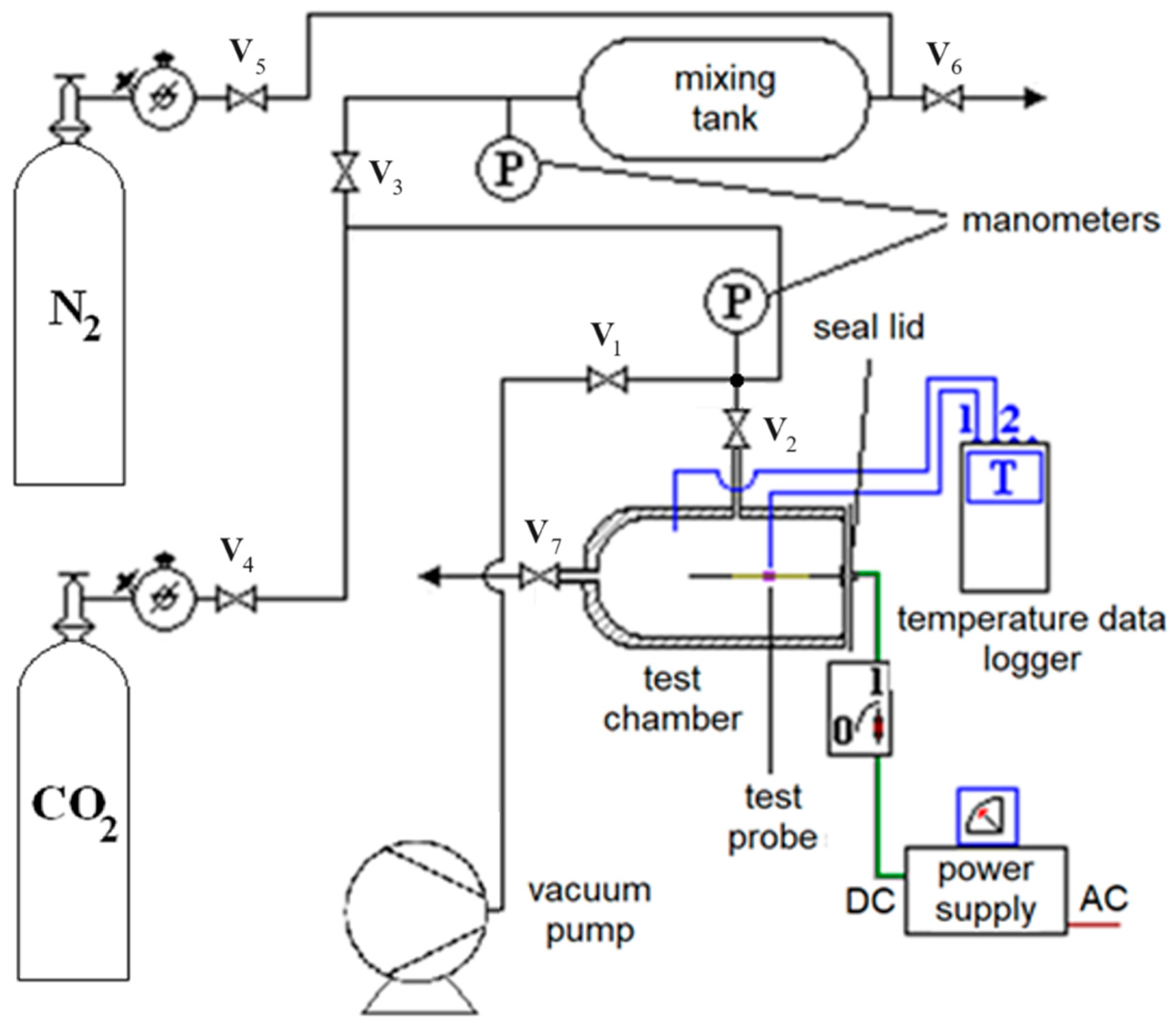
Figure 1 provides a schematic representation of the in-house-developed experimental setup used to study the combustion of metallic magnesium in binary mixtures of carbon dioxide and nitrogen. An essential component of the experimental system is the preparation step of the gas mixture based on partial pressures. The testing chamber, ignition system, and measuring equipment constitute the primary elements of the experimental setup. The pipes, testing chamber, and preparation tank are connected to a vacuum pump to ensure the complete removal of air. The test chamber is a cylindrical stainless-steel tube with an inner diameter of 62 mm, a thickness of 3.5 mm, and a length of 105 mm. The steel of the combustion chamber walls does not influence the studied process under the considered experimental conditions. One end is equipped with a welded cover, including a depressurization outlet, while the other end features a tight closure and elements for securing and supporting the magnesium sample. Pressurized gas bottles serve as the gas sources, and the desired gas mixture composition is obtained in a cylindrical stainless-steel tank with a capacity of 2 L, which is then fed into the testing chamber. Both the gas mixture preparation tank and the test chamber are equipped with analogue pressure gauges (Ferro, Poland, max. 10 ata, 0.1% accuracy). Temperature measurements in the test chamber are performed using two thermocouples (Pt 100) connected to a data logger (Sper Scientific, Visalia, CA, USA 800024 Thermocouple Thermometer, 4 Channel Datalogging).
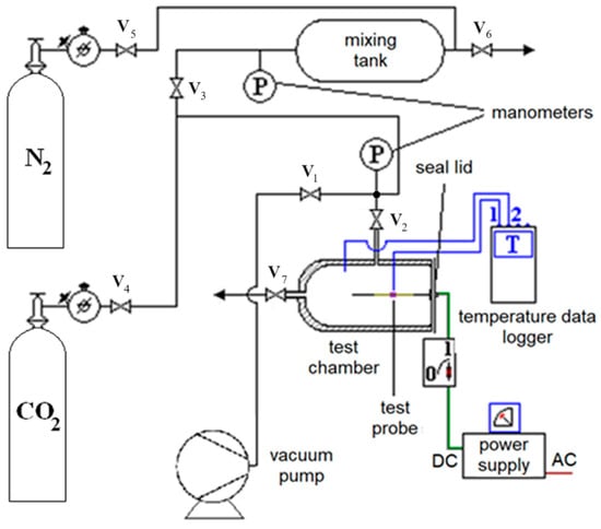
Figure 1.
Experimental setup for Mg combustion (V1–V7 − valves).
The magnesium samples used in this study are segments of magnesium tape, measuring 4 mm in width, 2.5 mm in thickness, and approximately 10 mm in length. Commercially pressurized gas cylinders are utilized as the gas sources.
2.2. Preparation System for Gas Mixture
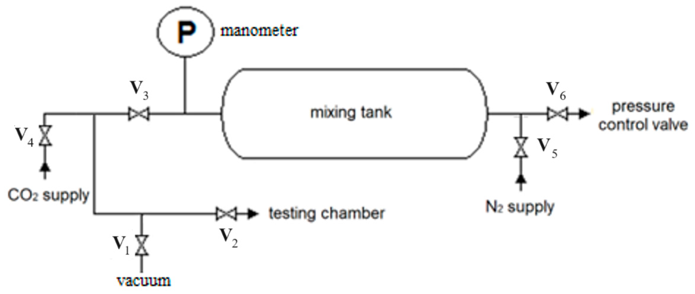
The key element of this system is the mixing vessel (see Figure 2). Nitrogen and carbon dioxide gases are supplied from gas bottles, and the gas feeding routes are equipped with manual valves. The preparation vessel includes a pressure gauge and can be connected to a vacuum pump for depressurization purposes. Prior to usage, the gas preparation system was evacuated by connecting it to a vacuum pump and also, the gas mixing system was vacuumed (valves V1 and V2 are open).
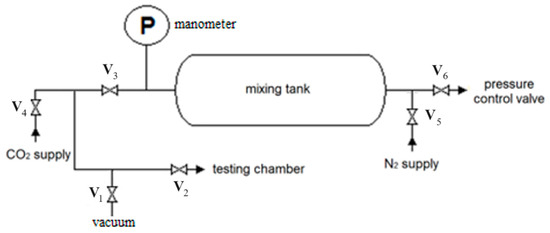
Figure 2.
The experimental setup for preparing the gas mixture (V1–V6 − valves).
The mixing chamber is connected to the first gas cylinder (CO2) allowing the vessel to be pressurized up to a specified pressure, denoted as P1 (V3 and V4 valves open). Then, the other gas, N2, is introduced until the pressure reaches 4 bars, which is higher than P1 (V5 open). Once the desired gas mixture is achieved, it is fed into the combustion chamber (V2–V4 valves open).
2.3. Testing Chamber
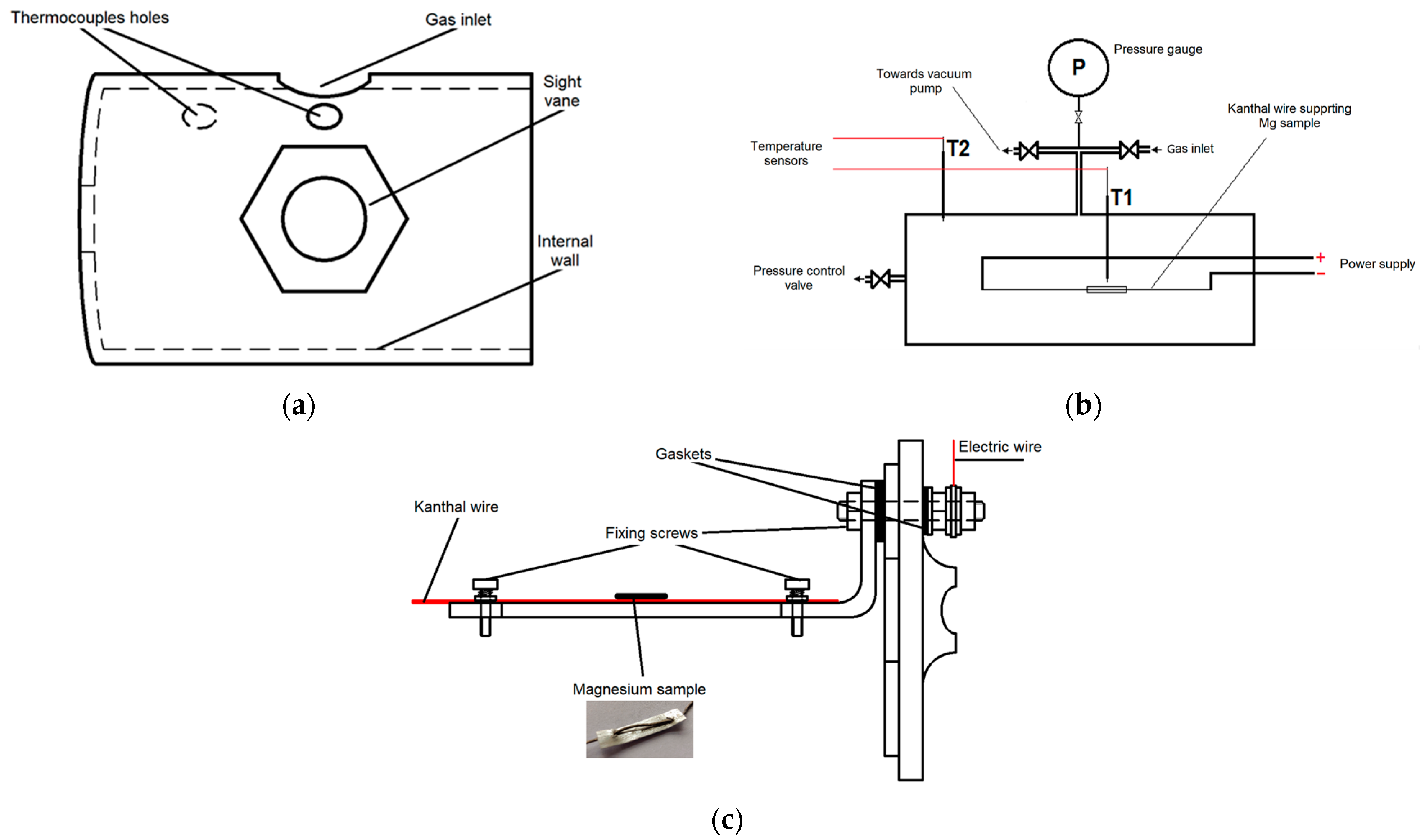
The test chamber consists of three main parts: the body (Figure 3a), chamber routes, and measuring devices (Figure 3b), and a cover with a sample igniting system (Figure 3c).
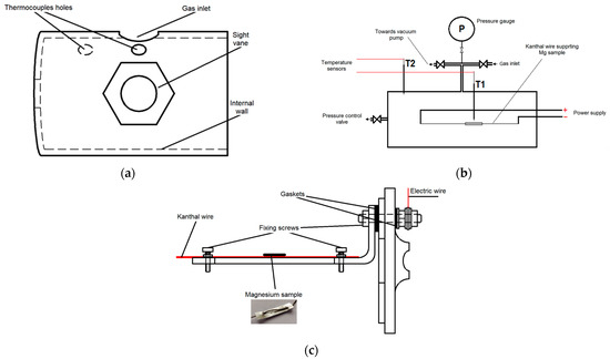
Figure 3.
Main elements of testing chamber: (a) Scheme of testing chamber; (b) Scheme of testing chamber routes and measuring devices; (c) Scheme of the cover with Mg sample igniting system.
The body of the test chamber, depicted in Figure 3a, is a stainless-steel cylinder with a thickness of 3.3 mm. It features a fixed cap at one end, a sight glass for observation, and openings for the inlet of the gaseous mixture and for securely attaching the thermocouples. Thermocouple T1 is placed at 5 mm from the axis, and thermocouple T2, at 5 mm from the inner wall of the cylindrical combustion chamber. The temperature measuring points were chosen in order to avoid direct influence of the heating resistor and chamber wall temperatures. The purpose of this experiment is to measure temperature values in the gas phase inside the combustion chamber.
In Figure 3b, a simplified diagram illustrates the interconnected routes associated with the test chamber. The primary route is the gas supply path, which connects to the gas mixture preparation vessel, as shown in Figure 3b. The exhaust path from the test chamber merges with the gas supply path and is connected to a vacuum pump (Figure 1). A pressure gauge is positioned between the valves and the body of the test chamber. During the experiments, all valves indicated in Figure 3b, except for the valve on the manometer connection path, remain closed. Additionally, the test chamber is equipped with a sampling valve.
The cover of the test chamber (Figure 3c) is placed in the inner section of the body described in Figure 3a. It contains a support structure for the wire and the necessary connections for the power supply. The Kanthal wire, along with the magnesium sample, is positioned so that the middle of the magnesium sample aligns with the sight glass for observation. The cover is equipped with sealing and insulation gaskets at the screw connections for the electric cable (using electrically insulating washers) and at the attachment point to the cylindrical tube (using an O-ring). Prior to finalizing the experimental setup, several preliminary tests were conducted to determine the most suitable type of thermo-electric wire to be used.
This configuration ensures the proper functioning and integrity of the test chamber, facilitating the observation and analysis of the magnesium combustion process under controlled conditions.
2.4. Reactions Tests
To measure the mass of the magnesium samples, a Precisa XT 220A (Precisa Gravimetrics AG, Dietikon, Switzerland) analytical balance was utilized. The mass of the magnesium sample was determined by weighing the Kanthal wire both with and without the attached magnesium and calculating the difference.
The gaseous mixture with the desired composition was prepared using a cylindrical tank with a capacity of 2 L. The composition was controlled by adjusting the partial pressures of the gas components. The tank was pressurized with one component to a specific pressure based on the desired composition, and then the next component was added until the desired test pressure was reached. Prior to usage, the cylinder was evacuated using a vacuum pump to remove any air traces, followed by pressurization and depressurization cycles with CO2 to effectively eliminate the residual air from the tank.
The test chamber was pressurized with the gas mixture prepared in the cylindrical tank. Before pressurization, the test chamber was also evacuated using a vacuum pump to achieve a residual pressure of 0.1 mBar. Pressurization and depressurization cycles were performed in the test chamber to remove any remaining air traces in the system. A sight vane was incorporated into the test chamber to allow the visual monitoring of the test progress. Each test was recorded using video footage, which began 5 s prior to closing the electrical circuit of the Kanthal wire with the magnesium sample. The video recording continued until the temperature T1 dropped below 100 °C. Additionally, a device displaying the T1 and T2 temperature values was used (Figure 1). Several runs were performed for each category under consideration.
The tests were organized into three groups based on the gas composition: group A with concentrations up to 40% CO2, group B with approximately 50% CO2, and group C with concentrations exceeding 60% CO2. The working pressure values were set at 3 and 2 bars (gauge pressure). The mass of the magnesium sample used in each test was approximately 11.5 mg.
This experimental setup and procedure allowed for precise measurements and recording of the Mg combustion process under different gas compositions and pressures, facilitating further analysis and investigation.
Mg reacts with CO2 based on the general reaction (1):
2Mg + CO2 = 2MgO + C,
When Mg undergoes combustion in CO2, the calculated enthalpy of reaction ΔHR has been determined to be −810.1 kJ mol−1, with details given in Table S1. For comparison, the combustion of methane has an enthalpy of reaction of −818 kJ mol−1 [27].
It is also possible to generate magnesium carbonate, according to the equation created by Abbud-Madrid et al. [23]:
MgO + CO2 = MgCO3,
Reina et al. [22] and Abbud-Madrid et al. [23] also suggested the following possible reaction for the studied system:
Mg + CO2 = MgO + CO,
However, as indicated by Abbud-Madrid et al. [23], the kinetic rates of these three reactions are not precisely known. Compounds such as CO and MgCO3 are disregarded in this study primarily due to the low sample weight and the relatively high volume of the combustion chamber, which favor Reaction (1). This observation is supported by SEM-EDX analysis results.
3. Results and Discussion
The temperature evolution, both near the sample and at the wall, during the experimental tests was analyzed by extracting data from the video recordings. Additionally, the ignition and burning times were determined based on the video recordings. To exemplify, several tests from each category were considered.
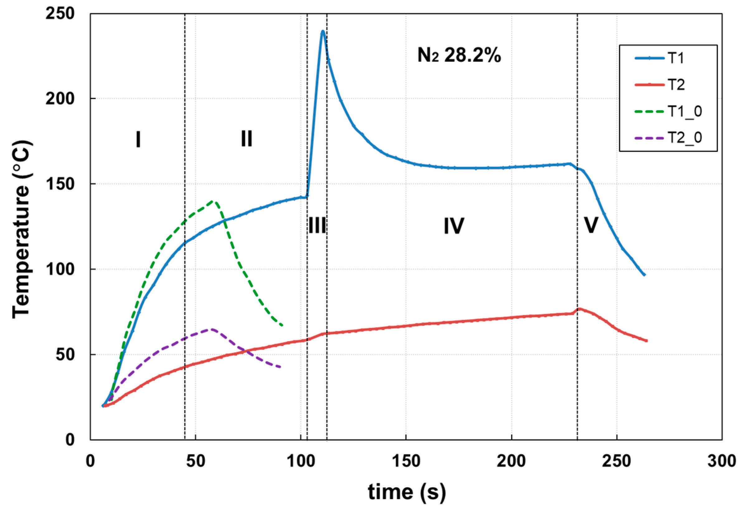
The recorded temperature profiles revealed distinct stages in the combustion process under investigation, as depicted in Figure 4 (corresponding to test 16 in Table 1).
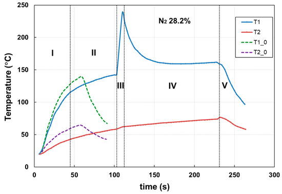
Figure 4.
Stages (separated by vertical dashed lines) of the combustion process of Mg in CO2–N2 mixtures at 2 ata. (T1_0 and T2_0—temperature profiles in absence of Mg, near the heating wire, and the chamber wall, respectively; T1 and T2—temperature profiles measured near the heating wire and near the chamber wall, respectively, in the presence of Mg).

Table 1.
Experimental design.
By analyzing the temperature curves, the following distinct stages of the overall process can be identified: Electric resistance heating (I): During this stage, the Mg sample and the test chamber are subjected to heat from the electric power source. The heat input from the source remains constant throughout this stage. Melting of the Mg sample (II): This stage corresponds to the period in which the Mg sample absorbs heat from the source, resulting in the melting of the sample. Subsequently, the sample undergoes vaporization. The demarcation between the initial two specified stages is determined at the point in time where there is a change in the slope of the temperature profiles during Mg combustion. This alteration in slope is primarily attributed to phase transformation accompanied by heat absorption. Reaction/ignition of the Mg sample and combustion (III): This stage marks the reaction and ignition of the Mg sample in the presence of CO2. The inception of the peak corresponds to the ignition time. It is characterized by a sudden increase in temperature within the reaction chamber due to the heat released by the Mg-CO2 reaction. Post-reaction cooling with the electrical resistance still enabled (IV): In this stage, the heat from the reaction is dissipated while the electric resistance heating remains active. Cooling of the reaction chamber (V): During this stage, the reaction chamber undergoes cooling through heat dissipation into the surrounding environment.
The reaction of Mg with CO2 represents a potential source of energy, with a large amount of heat being released in a very short time using a very small amount of Mg.
As shown in Figure 4, in the first stage of the process, the temperature increases due to the electric resistance heat. This generated heat results in the heating of the combustion chamber, gas mixtures in the combustion chamber, and compensates and contributes to the heat loss, and the energy equation can be expressed as follows:
where QER is the heat generated by the electric resistance, J; QCC = mCC × CpStainless Steel × (T1−T2), J; QGas = mGas × CpGas × (T1-T2), J; Qloss = α × A × (Twall - Tambient)∙ti, J; mCC and mGas—weight of combustion chamber and Gas, respectively, kg; CpStainless Steel and CpGas—specific heat of stainless steel and gas mixture, respectively, J kg−1 K−1); (T1−T2)—difference between interior and exterior temperatures, °C; ti—stage i time span, with i = 1–4; α—individual thermal transfer coefficient, W m−2 K−1; A—external surface of combustion chamber, m2; Twall—temperature on the combustion chamber wall, °C; Tambient—room temperature, °C.
In the second stage, Mg phase transformation (melting/vaporization) takes place. This is a process that consumes electric generated heat. Thus, a fraction of the electric generated heat is used by these processes, modifying the temperature profile according to the following equation:
where QPT is phase transformation heat, J (QPT = mMg × ΔHM); ΔHM—enthalpy of melting process.
In the third stage, the combustion process takes place in a very short period of time, with the temperature of the gaseous phase increasing significantly:
where QC is the combustion generated heat, J (QC = mMg × ΔHC/MMg), ΔHC—enthalpy of combustion process, J mol−1.
Due to the combustion taking place in a very short time, the entire combustion heat contributes to the increase in the temperature of the gas mixture in the combustion chamber.
Table 2 shows the case of the test presented in Figure 5c (P = 2 ata), with heat values estimated based on the charted temperature time variation and Equations (4)–(6), for different stages.
Table 2.
Calculations of process heats during heating, melting, vaporization, and combustion of Mg in N2-CO2 atmosphere.
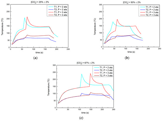
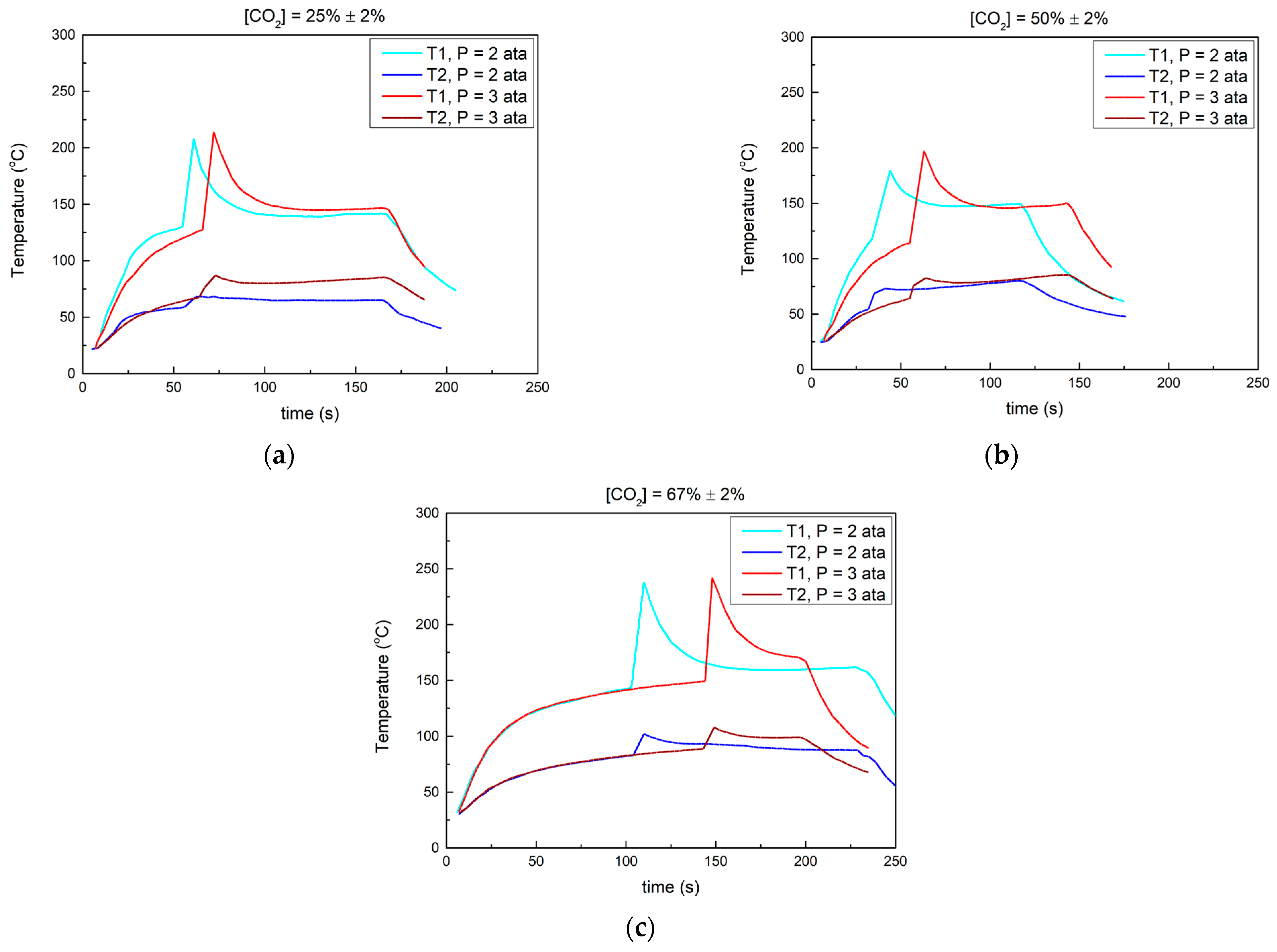
Figure 5.
Influence of pressure on temperature profiles (T1—in the vicinity of the sample, T2—near the wall of the reaction chamber), experimental conditions: (a) [CO2] 25 ± 2%, P = 2 and 3 ata, respectively; (b) [CO2] 50 ± 2%, P = 2 and 3 ata, respectively; (c) [CO2] 67 ± 2%, P = 2 and 3 ata, respectively.
For stages 1 and 2, most of the provided heat is used for chamber heating. Also, the heat balance values reveal the necessity that an adequate amount of heat is transferred to sustain the oxidation reaction. In stage 3, the estimated value of the heat of combustion for magnesium in N2-CO2 atmosphere is 78.4 kJ mol−1. This estimated value should be contextualized by taking into account the concentration of N2 (~33%), the readings of temperature values with the accuracy of 1s (a significant part of the T-t peak is missing due to experimental limitations), and the non-adiabatic regime of the conducted process. The reaction takes place predominantly between Mg and CO2 from the gaseous mixture. The amount of Mg considered in the experiments was considered based on preliminary calculations so that, regardless of the composition of the gas mixture, the Mg amount would react completely. Therefore, the heat of the reaction is expected to be relatively similar.
In the fourth stage, though the electric resistance is still powered on, the temperature decreases down to a plateau until the electric resistance is powered off. The generated heat is mostly consumed to compensate Qloss (QER = Qloss).
By carefully considering the heat balances in each stage of Mg combustion, one can optimize energy conversion efficiency, minimize energy losses, and enhance overall system performance. These considerations are crucial for achieving sustainable and efficient combustion processes, reducing the environmental impact of such processes, and promoting the use of Mg as a clean energy source.
3.1. Influence of Pressure on Temperature Profiles
In the first group of tests, which involved CO2 concentrations of approximately 25% or lower, two specific tests were exemplified. These tests were conducted under constant magnesium mass (11 mg) and a carbon dioxide concentration of 25 ± 2%. The gas pressure in the reaction chamber was maintained at 2 ata and 3 ata, respectively.
Figure 5a illustrates the temperature profiles obtained for Mg combustion at CO2 concentrations of 25 ± 2%. Preliminary experimental tests showed that no combustion took place at lower CO2 concentrations. The reaction pressure had an influence on both the ignition time and the maximum temperature reached during combustion. When the pressure increased from 2 to 3 ata, the ignition time increased from 55 to 66 s. Additionally, the maximum temperature was reached at a higher pressure, as indicated by the higher temperature values in the post-reaction zone (145 °C compared to 139 °C).
For CO2 concentrations of about 50%, two tests were conducted with a constant magnesium weight (11 mg), a carbon dioxide concentration of 50 ± 2%, and gas pressures of 2 ata and 3 ata, respectively, as shown in Figure 5b.
The ignition time values changed from 34 to 55 s as the pressure increased from 2 to 3 ata. The maximum combustion temperature at 3 ata exceeded the corresponding value at 2 ata. However, the post-combustion temperature (approximately 150 °C) did not appear to be significantly influenced by the pressure.
The tests carried out at higher CO2 concentrations (67 ± 2%) resulted in the temperature profiles presented in Figure 5c.
During the initial stages of the process, the temperature profiles of T1 overlap regardless of the pressure value. The maximum combustion temperature is achieved at a pressure of 3 ata, and the combustion times are 130 s, at the pressure of 3 ata and 144 s at 2 ata. Furthermore, the post-combustion temperature values remain approximately equal and unaffected by the pressure, measuring around 171 °C.
The temperature values measured near the wall (T2), in all cases, exhibit profiles that are influenced by the values near the sample (heating resistance), with a lower pressure impact. However, the observed differences can be explained by changes in the thermal properties of the gas mixtures (specific heat, thermal conductivity, density, and viscosity) due to variations in temperature, composition, as well as heat loss.
The gas pressure in the reaction chamber has a notable impact on both the heat released during the processes and the ignition time of Mg. However, the extent of this influence varies depending on the composition of the gas mixture, with a greater effect observed at low concentrations of CO2. Figure 5 illustrates the impact of pressure values in the combustion chamber on ignition time. At a pressure of 2 ata, lower ignition temperature values are observed. The slight disparity in ignition time values at 2 and 3 ata may stem from variations in the thermal properties of the gas and the intensity of heat transfer. Legrand et al. [28] demonstrated that the ignition probability of Mg particles in a CO2/Ar atmosphere is influenced by the pressure value.
3.2. Influence of CO2–N2 Mixture Composition on Mg Combustion
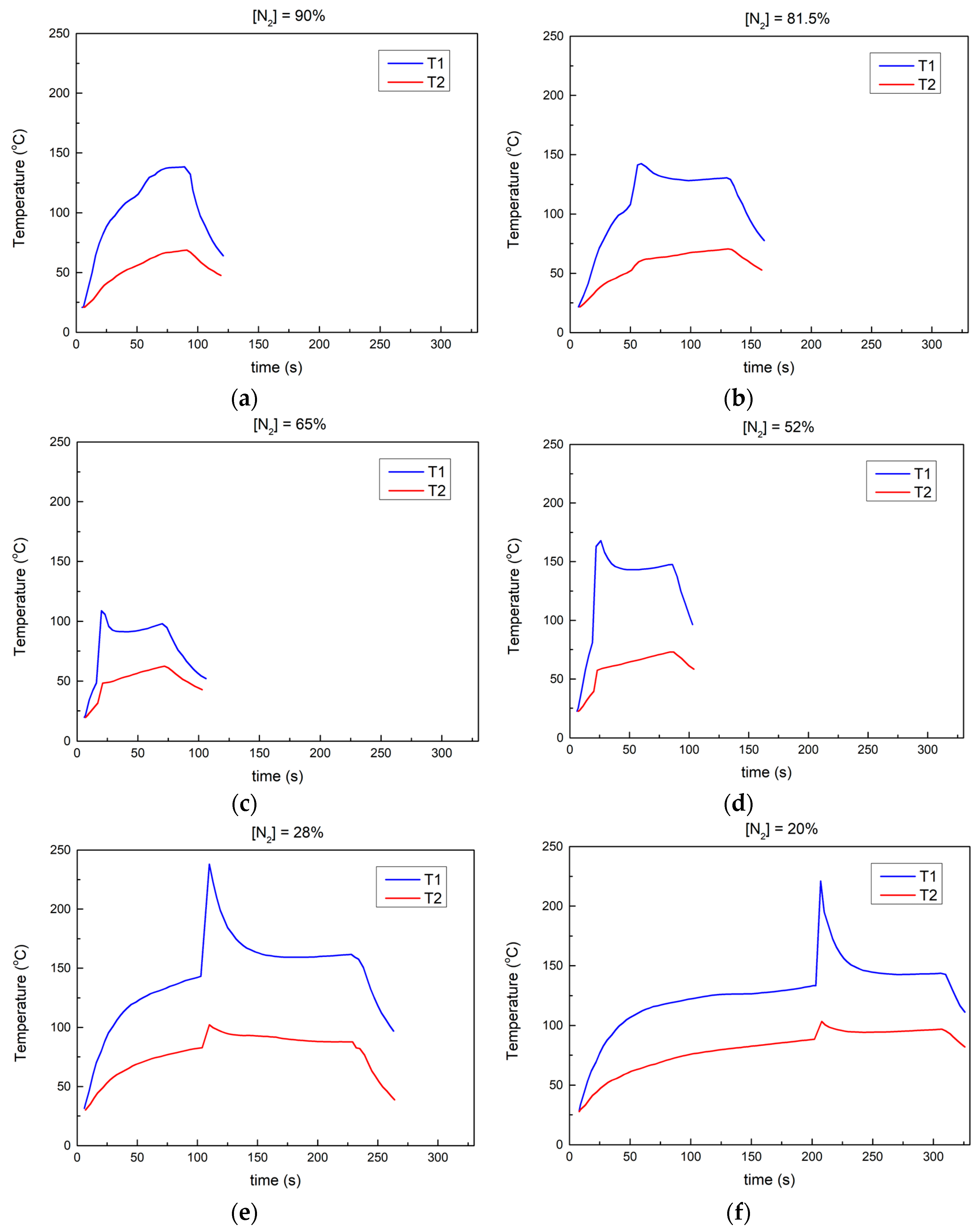
Figure 6a–f displays the temperature profiles of Mg combustion at 2 ata within mixtures featuring varying CO2 concentrations, ranging from 10% to 80%.
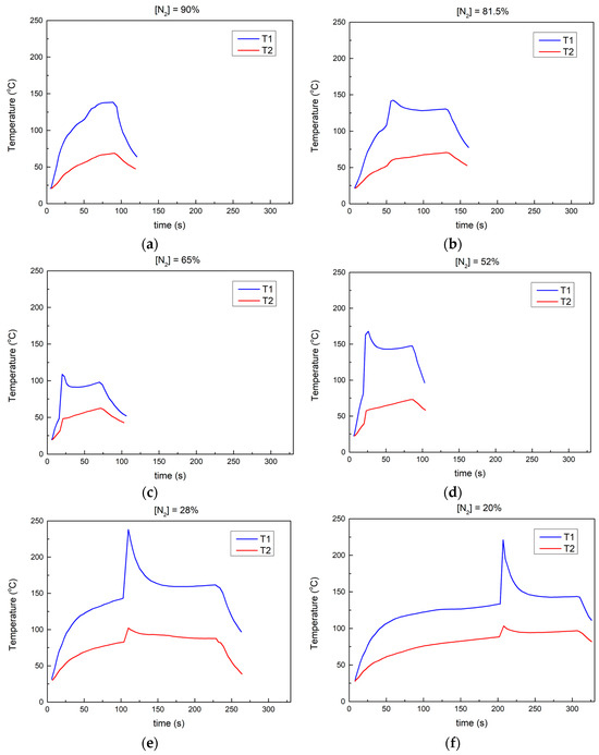
Figure 6.
Temperature profiles (T1—in the vicinity of the sample, T2—near the reaction chamber wall) during Mg combustion in mixtures with CO2 content at 2 ata: (a) 10%; (b) 19.5%; (c) 35%; (d) 48%; (e) 72%; (f) 80%.
The concentration of CO2 in the gas mixture has a global influence on the process by affecting the ignition time, the ignition temperature, the heat brought into the system by the heating resistance, and the heat loss.
In most cases, except for one instance at 10% CO2 concentration where the reaction does not seem to take place, a peak in temperature can be observed after the initiation of the reaction. The figures also show the temperature profiles in the absence of the sample (reaction), represented by dotted lines.
The T1 profiles provide insights into the stages depicted in Figure 6. Even at low CO2 concentrations, the melting/vaporization of the Mg sample occurs, although ignition does not occur. The maximum temperature reached by T1 increases with higher CO2 concentrations. The ignition time for cases (b) and (c) exhibits practically the same value of 50 s.
At a CO2 concentration of 50%, Figure 6d, the ignition time values are relatively close and lower compared to those in the experiments conducted at low CO2 concentrations. The maximum temperature T1 observed remains approximately constant at around 155 °C. The post-combustion temperature is influenced by the CO2 concentration, with T1 values reaching about 148 °C at a concentration of 53% compared to 140 °C at 47.8% CO2 concentration.
By analyzing the temperature profile depicted in Figure 6e,f, the stages of the overall process shown in Figure 4, can also be depicted. During combustion, the temperature rapidly increases for a duration of 2–5 s. However, after the completion of the reaction, the temperature remains relatively constant for durations ranging between 50 and 100 s, depending on the concentration of the CO2-N2 mixture.
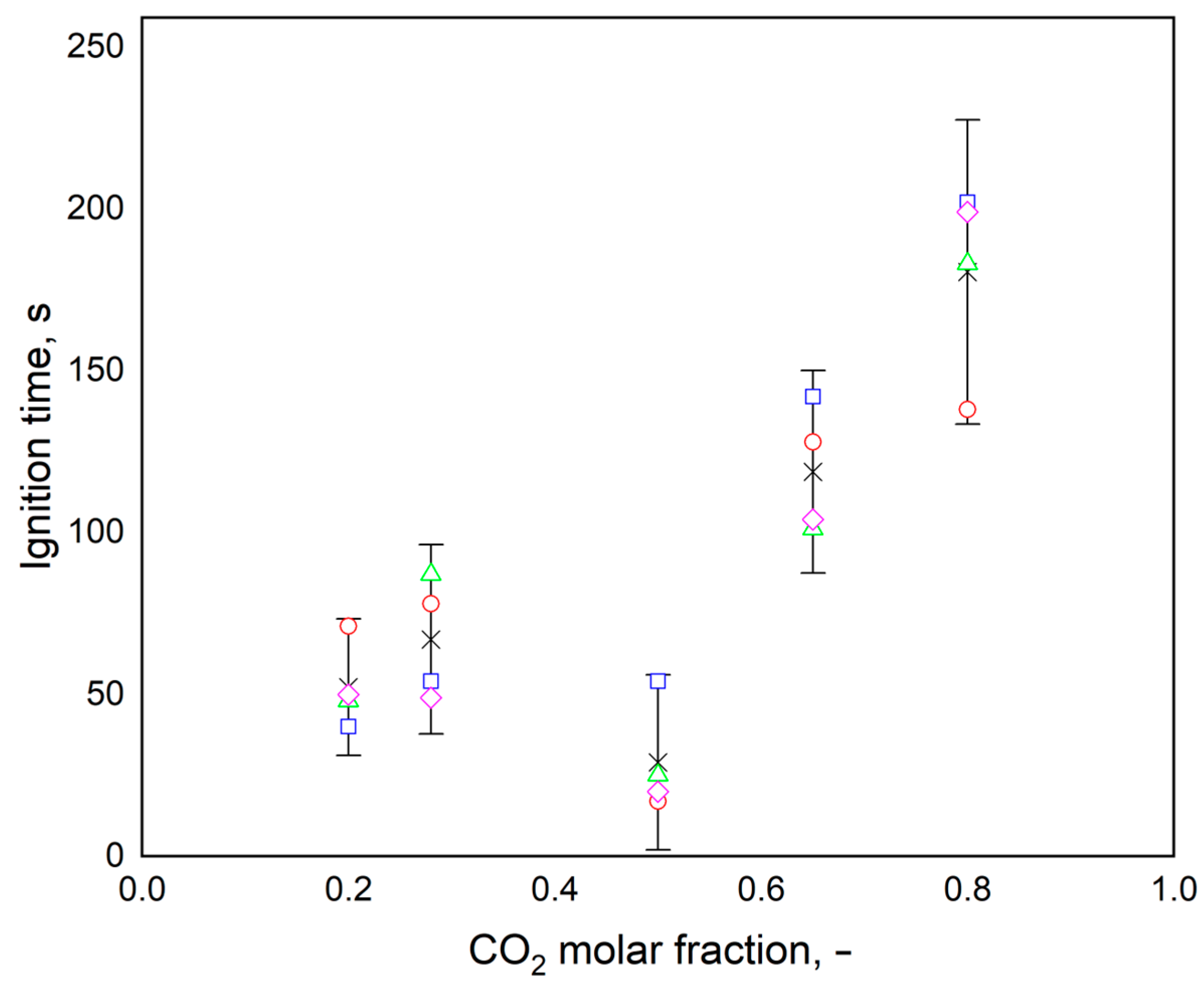
Figure 7 shows the experimental values, the average value and the error bars obtained for ignition time at various compositions of CO2-N2 mixture.
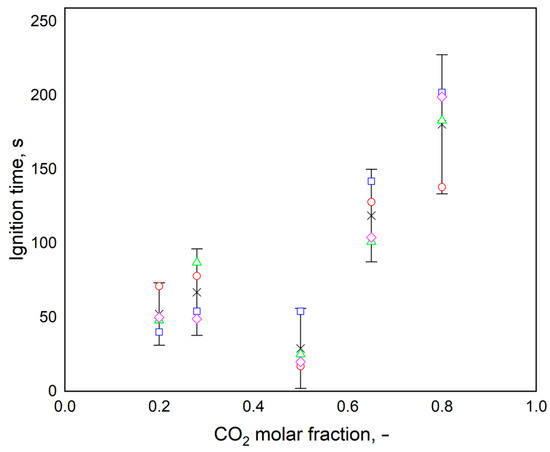
Figure 7.
The influence of the gas mixture composition on the ignition time (◊, □, ○, Δ—tests repeated under similar conditions; x—average value).
The ignition time values appear to be within the range of 30–100 s, with occasional lower values noted at 50% CO2 content. Experimental evidence supports the conclusion that the ignition time is likely quasi-constant at CO2 molar fraction values of 0.5 or lower. However, with higher CO2 content, there is an observed increase in ignition time, reaching up to 200 s. This trend could be attributed to the thermal properties of the gas mixture within the combustion chamber, potentially leading to a reduction in heat input and a delay in the phase transformation of Mg (Figure S1 shows the thermal properties of gases and their mixture).
The experimental runs not only demonstrate the use of the Mg and CO2 reaction as an energy source, in the absence of oxygen, but also support the hypothesis of using Mg for the selective separation of industrial gas streams containing CO2.
Significant reductions in CO2 concentration were observed in binary gas mixtures comprising carbon dioxide and nitrogen during the Mg combustion. This observed decrease, coupled with the energy input, suggests a potential path for diminishing CO2 levels in gaseous mixtures, with significant inferences in environmental protection. Consequently, this phenomenon could lead to an innovative CO2 sequestration technique, yielding MgO and C as byproducts. These gas mixtures were prepared by mixing pure gases under controlled laboratory conditions. The experiments revealed that the Mg-CO2 reaction occurs at CO2 concentrations higher than 10%. This finding suggests the potential application of magnesium for efficient removal of CO2 from gas mixtures, particularly in high-temperature environments such as combustion gases.
3.3. Combustion Residue Analysis
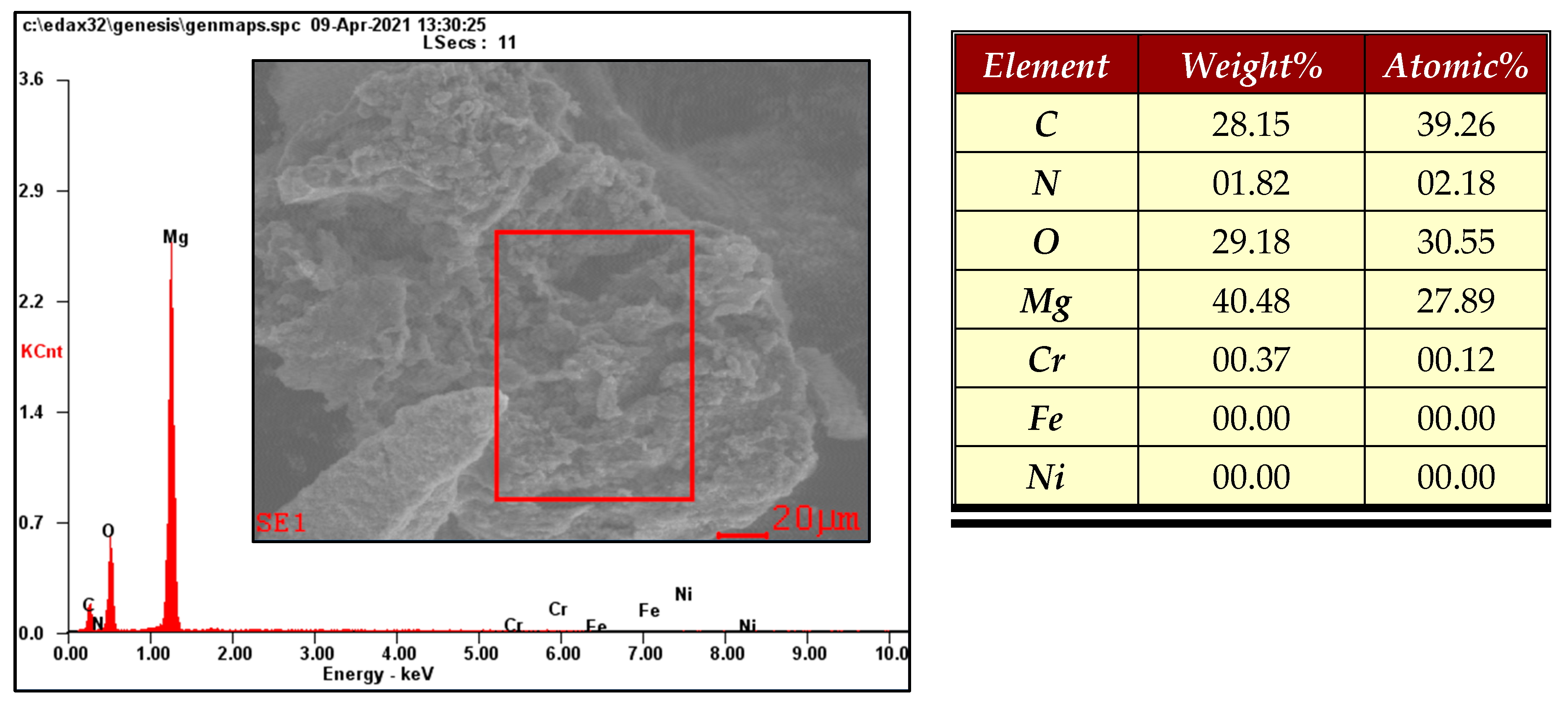
The morphology of combustion residue of the Mg microparticle was characterized by SEM-EDX and is shown in Figure 8.
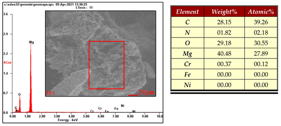
Figure 8.
SEM image of Mg sample (The rectangular red line is the analyzed area).
Figure 8 illustrates that the residue left after the combustion of Mg particles appears relatively flat and is slightly embedded in the surface of the glass substrate. The observation of the residue clearly shows that its morphology is not attributed to airborne debris but rather to the solidification of falling oxides. Elemental analysis confirms the presence of magnesium, oxygen, and carbon in the residue. The analysis of the solid residue shows that C and MgO were obtained as reaction products. The obtained results are consistent with those reported in the literature [29].
Figure S2 in the supplementary material shows that Mg3N2 was not generated during the conducted process. The reaction conditions are not favorable for obtaining magnesium nitride, which is not stable in the atmosphere, resulting in NH3. The SEM-EDX analysis shows the presence of a small amounts of nitrogen on the surface of the combustion that can be attributed to the inherent exposure of the analyzed samples to the atmosphere.
4. Conclusions
The experimental investigation of Mg combustion was conducted using a custom-built experimental setup. Based on our results and a thorough literature analysis, several conclusions have been drawn.
The combustion process of Mg can be divided into several distinct stages, namely heating, melting, vaporization, ignition, combustion, and cooling. Within these stages, the melting time stands out, as it is notably longer compared to both the evaporation time and the gas phase combustion time. The melting process plays a key role in the overall combustion process.
During magnesium ignition, the initial outer flame displays a spherical vapor-phase pattern, similar to what has been reported during the combustion of Mg particles in CO2/Ar mixtures [28]. This observation indicates that the reaction zone or flame thickness of Mg vapor in the combustion chamber has a spherical structure. Both pressure and gas composition exert significant effects on ignition delay and combustion time. The ignition delay time decreases as the chamber pressure increases.
The CO2 concentration within the combustion chamber has a notable influence on the combustion process, particularly the ignition time, ignition temperature, the heat brought into the system by the heating resistance, and the heat loss.
Since the gas phase combustion time is quite brief, the ignition delay time dominates the overall combustion duration.
Following the analysis of the energy balance, the reaction of Mg with CO2 emerges as a potential energy source in oxygen-deprived atmospheres. Additionally, it presents an alternative approach to CO2 sequestration in the form of Mg and C oxides. Other gas mixtures can also be considered, especially if they are of technical importance.
Supplementary Materials
The following supporting information can be downloaded at: https://www.mdpi.com/article/10.3390/chemengineering8020041/s1; Figure S1: Specific heat (a) and thermal conductivity (b) of N2−CO2 (1:1) mixture; Figure S2: Combustion chamber after test; Table S1: Reaction enthalpy for magnesium combustion in carbon dioxide (reaction 1).
Author Contributions
I.B.: conceptualization, methodology, formal analysis, investigation, writing—original draft preparation; M.S.S.: conceptualization, methodology, investigation, formal analysis, data curation, validation, writing, review and editing, funding acquisition; A.M.A.: formal analysis, data curation, writing—original draft preparation; E.T.I.-T.: methodology, investigation, validation, review; G.L.: methodology, investigation, validation, review; I.M.: conceptualization, methodology, validation, writing, review and editing, resources, supervision, funding acquisition. All authors have read and agreed to the published version of the manuscript.
Funding
This research received no external funding.
Data Availability Statement
Data available upon request.
Conflicts of Interest
The authors declare no conflicts of interest.
References
- Nishii, K.M.; Akiyama, H.; Koizumi, K.; Komurasaki, K. Combustion of Magnesium Wires with Oxygen and Water Vapor. Combust. Sci. Technol. 2023, 195, 2364–2380. [Google Scholar] [CrossRef]
- Feng, Y.C.; Xia, Z.X.; Huang, L.Y.; Ma, L.K.; Yang, D.L. Experimental Investigation on the Ignition and Combustion Characteristics of a Single Magnesium Particle in Air. Combust. Explos. Shock. Waves 2019, 55, 210–219. [Google Scholar] [CrossRef]
- Lomba, R.; Bernard, S.; Gillard, P.; Mounaïm-Rousselle, C.; Halter, F.; Chauveau, C.; Tahtouh, T.; Guézet, O. Comparison of Combustion Characteristics of Magnesium and Aluminum Powders. Combust. Sci. Technol. 2016, 188, 1857–1877. [Google Scholar] [CrossRef]
- Zhu, X.; Li, C.; Wei, R.; Ao, W.; Guo, Y.; Hu, J.; Yang, J.; Hu, C. Quantitative analysis of the carbon generation characteristics during Mg/CO2 combustion: Implications for suppressing carbon deposition. Aerosp. Sci. Technol. 2020, 103, 105966. [Google Scholar] [CrossRef]
- Mathandhu, S.N.; Luo, A.A.; Neelameggham, N.R.; Nyberg, E.A.; Sillekens, W.H. Essential Readings in Magnesium Technology; The Minerals, Metals & Materials Society and John Wiley & Sons, Inc.: Hoboken, NJ, USA, 2014. [Google Scholar]
- Pekguleryuz, M.O.; Kainer, K.U.; Arslan, K.A. Fundamentals of Magnesium Alloy Metallurgy; Woodhead Publishing Limited: Cambridge, UK, 2013. [Google Scholar]
- Li, Y.; Hu, C.; Zhu, X.; Hu, J.; Hu, X.; Li, C.; Cai, Y. Experimental study on combustion characteristics of powder magnesium and carbon dioxide in rocket engine. Acta Astronaut. 2019, 155, 334–349. [Google Scholar] [CrossRef]
- Aleksandrova, Y.P.; Roshchina, I.N. Interaction of Magnesium with Gases Moscow Aviation Technology Institute. Met. Sci. Heat Treat. 1977, 19, 218–221. [Google Scholar] [CrossRef]
- Shafirovich, E.Y.; Goldshleger, U.I. Ignition and Burning of Magnesium Particles in Oxides of Carbon. Combust. Explos. Shock Waves 1990, 26, 1–7. [Google Scholar] [CrossRef]
- Valov, A.; Yu, E.; Kustov, A.; Shevtsov, V.I. Spectroscopic Study of the Combustion of Solitary Magnesium Particles in Air and in Carbon Dioxide. Combust. Explos. Shock Waves 1995, 30, 431–436. [Google Scholar] [CrossRef]
- Barabulica, I.; Mamaliga, I. Separation of Waste Industrial Gases with Magnesium. Bul. Inst. Polit. Iaşi. 2019, 65, 21–36. [Google Scholar]
- Friedrich, H.E.; Mordike, B.L. Magnesium Technology Metallurgy, Design Data, Applications; Springer: Berlin/Heidelberg, Germany, 2006. [Google Scholar]
- Shand, M.A. The Chemistry and Technology of Magnesia; John Wiley & Sons, Inc.: Hoboken, NJ, USA, 2006. [Google Scholar]
- Wagh, A.S. Chemically Bonded Phosphate Ceramics Twenty-First Century Materials with Diverse Applications, 2nd ed.; Elsevier Ltd.: Amsterdam, The Netherlands, 2016. [Google Scholar]
- Walker, G. Solid State Hydrogen Storage Materials and Chemistry; Woodhead Publishing Limited: Cambridge, UK, 2008. [Google Scholar]
- Nelson, D.J. Magnesium Picolinate Compositions and Methods of Use. Patent WO2018/071601, 19 April 2018. [Google Scholar]
- Campbel, S.; Hollins, P.; McCash, E.; Roberts, M.W. Reaction of Carbon Dioxide with the Magnesium (0001). J. Electron. Spectrosc. Relat. Phenom. 1986, 39, 145–153. [Google Scholar] [CrossRef]
- Zhang, S.M.; Hu, C.B.; Xia, S.Y.; Li, L.; Wei, X.G. Ignition and Combustion of Magnesium Particles in Carbon Dioxide. Appl. Mech. Mater. 2012, 152–154, 220–225. [Google Scholar] [CrossRef]
- Fedoseev, V.A. Evaporation and Combustion Kinetics of Fine Drops and Particles. Fiz. Aerodispersnykh Sistem. 1969, 1, 98–114. [Google Scholar]
- Fedoseev, V.A.; Glushkov, V.E.; Sokolov, L.A. Ignition of Magnesium Particles in Different Media. Fiz. Aerodispersnykh Sistem. 1975, 6, 83–88. [Google Scholar]
- Laurendeau, N.M.; Glassman, I. Ignition Temperatures of Metals in Oxygen Atmospheres. Combust. Sci. Technol. 1971, 3, 77–82. [Google Scholar] [CrossRef]
- Reina, A.; Colombo, G.; DeLuca, L.; Maggi, F.; Lesniak, I.; Lempert, D.; Manelis, G. Magnesium and Aluminum Ignition in CO2 Atmosphere. In Proceedings of the XX AIDAA Congress, Milano, Italy, 29 June–3 July 2009. [Google Scholar]
- Abbud-Madrid, A.; Modak, A.; Branch, M.C.; Daily, J.W. Combustion of Magnesium with Carbon Dioxide and Carbon Monoxide at Low Gravity. J. Propuls. Power. 2001, 17, 852–859. [Google Scholar] [CrossRef]
- Frost, D.L.; Zhang, F.; Murray, S.B.; McCahan, S. Critical Conditions for Ignition of Metal Particles in a Condensed Explosive. In Proceedings of the 4th APS Topical Conference on Shock Compression of Condensed Matter, Baltimore, MD, USA, 31 July–5 August 2005. [Google Scholar]
- Shafirovich, E.Y.; Shiryaev, A.A.; Goldshleger, U.I. Magnesium and Carbon Dioxide: A Rocket Propellant for Mars Missions. J. Propuls. Power 1993, 9, 197–203. [Google Scholar] [CrossRef]
- Liu, J.; Liu, Z. In-cylinder thermochemical fuel reforming for high efficiency in ammonia spark-ignited engines through hydrogen generation from fuel-rich operations. Int. J. Hydrogen Energy 2024, 54, 837–848. [Google Scholar] [CrossRef]
- Green, D.W. Perry’s Chemical Engineer’s Handbook, 8th ed.; McGraw-Hill: New York, NY, USA, 2008. [Google Scholar]
- Legrand, B.; Marion, M.; Chauveau, C.; Gokalp, I.; Shafirovich, E. Ignition and Combustion of Levitated Magnesium and Aluminum Particles in Carbon Dioxide. Combust. Sci. Technol. 2001, 165, 151–174. [Google Scholar] [CrossRef]
- Shafirovich, E.Y.; Goldshleger, U.I. Combustion of Magnesium Particles in CO2/CO Mixtures. Combust. Sci. Technol. 1992, 84, 33–43. [Google Scholar] [CrossRef]
Disclaimer/Publisher’s Note: The statements, opinions and data contained in all publications are solely those of the individual author(s) and contributor(s) and not of MDPI and/or the editor(s). MDPI and/or the editor(s) disclaim responsibility for any injury to people or property resulting from any ideas, methods, instructions or products referred to in the content. |
© 2024 by the authors. Licensee MDPI, Basel, Switzerland. This article is an open access article distributed under the terms and conditions of the Creative Commons Attribution (CC BY) license (https://creativecommons.org/licenses/by/4.0/).