An Experimental Study of Heat Transfer in Pool Boiling to Investigate the Effect of Surface Roughness on Critical Heat Flux


Abstract
:1. Introduction
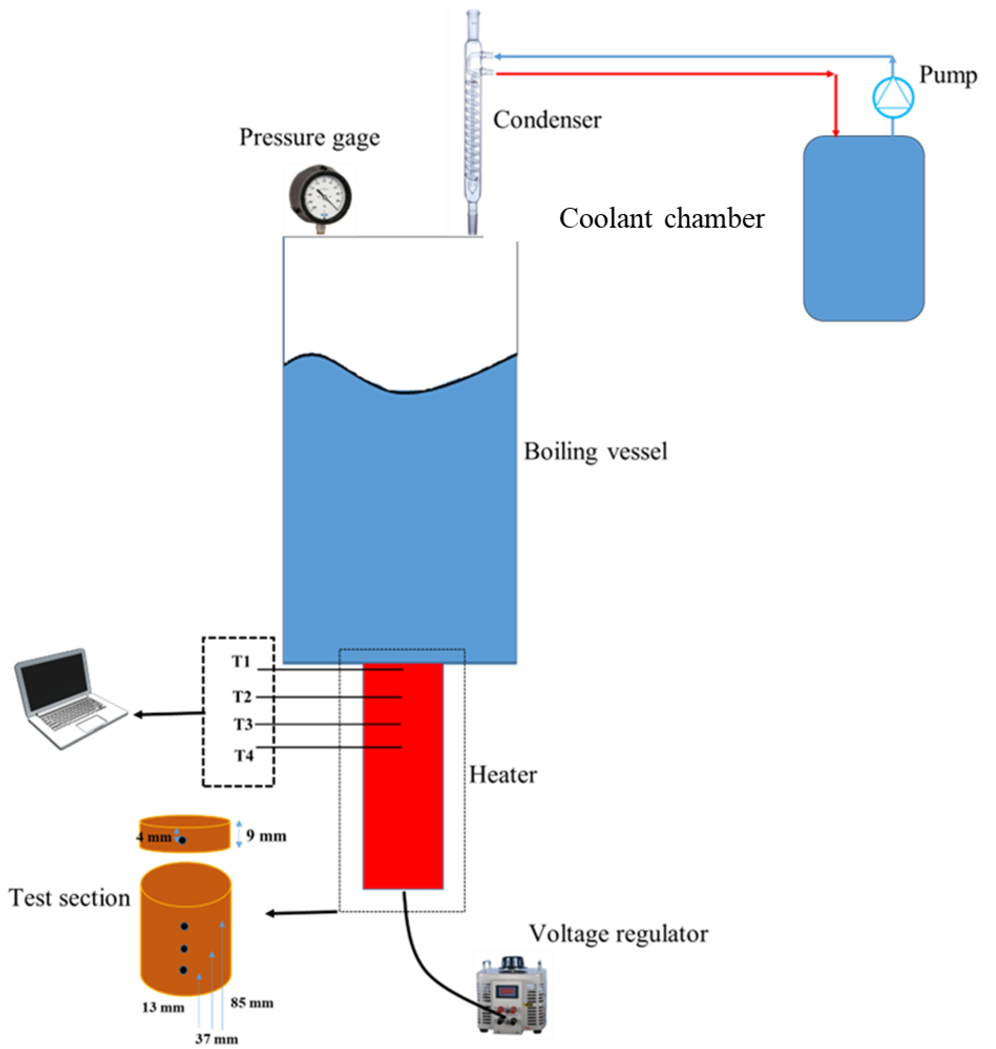
2. Materials and Methods
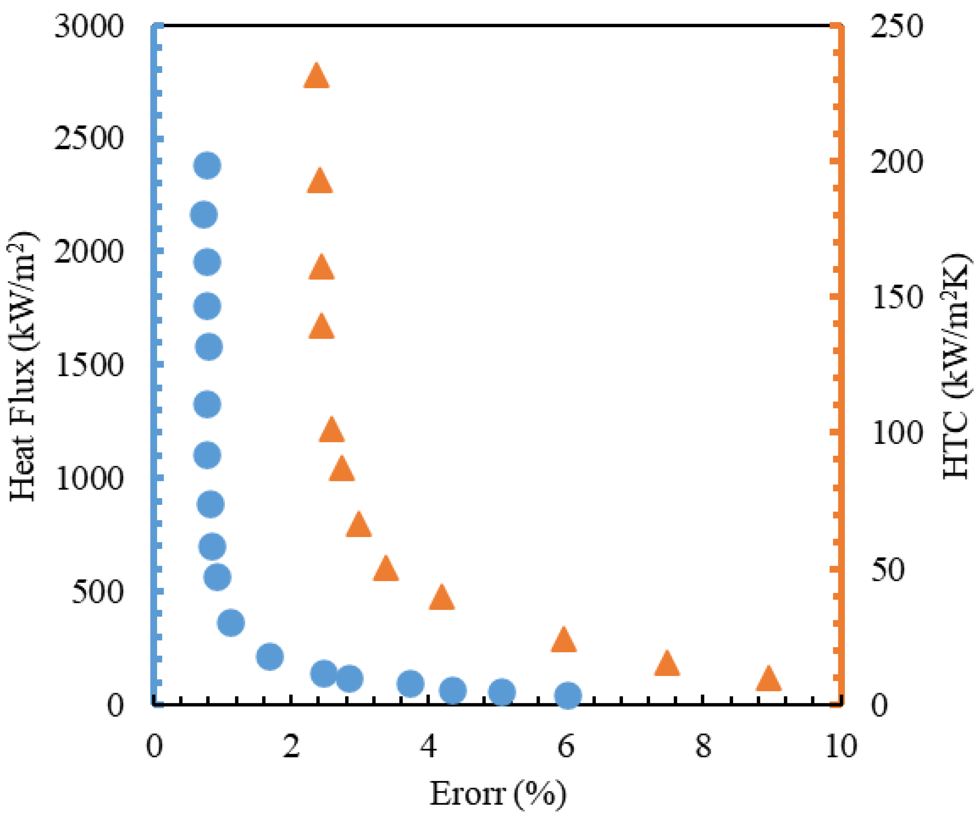
Uncertainty Analysis
3. Results and Discussion
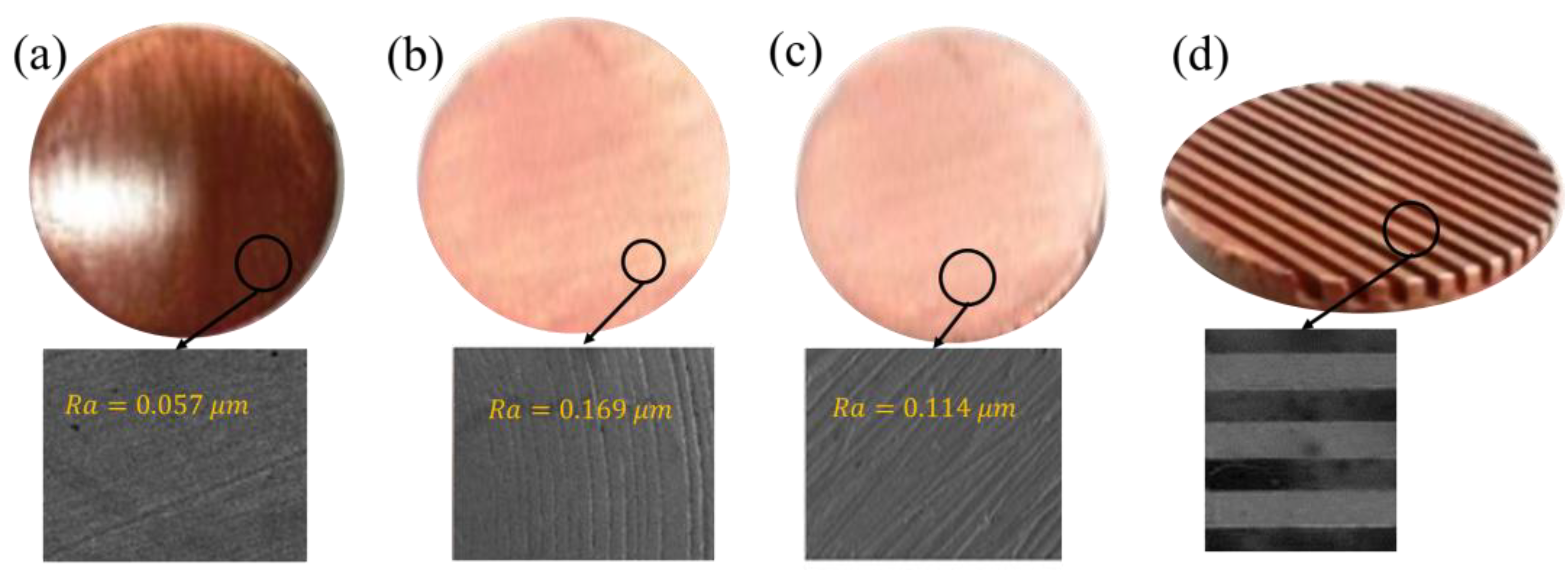
Pool Boiling Test of Various Surfaces in the Presence of Water
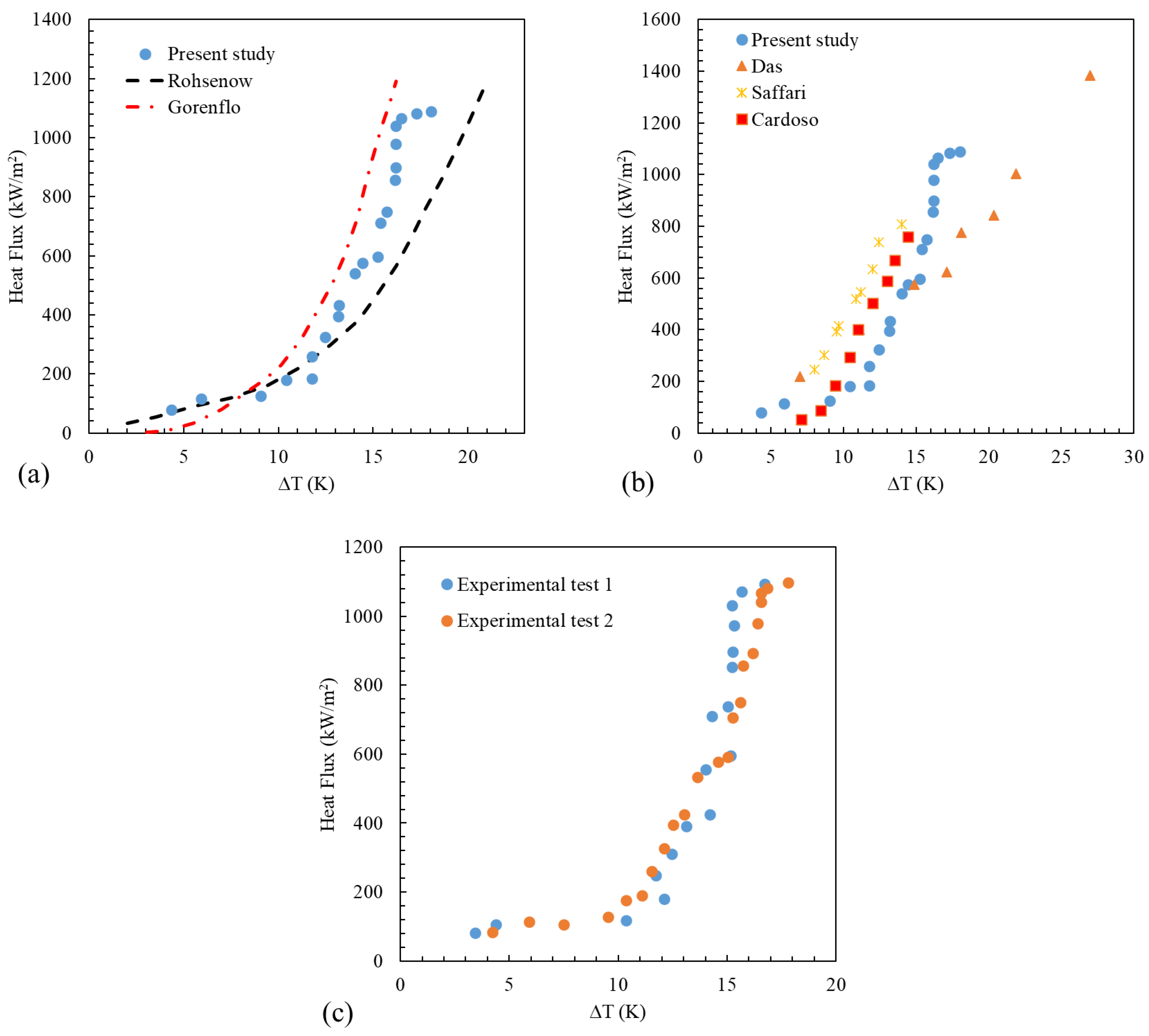
- (A)
- Comparison of data with experimental relationships in the field of boiling;
- (B)
- Comparison with the results of experimental data of other researchers in this field;
- (C)
- Holding a repeatability test.
4. Conclusions
Funding
Data Availability Statement
Acknowledgments
Conflicts of Interest
Nomenclature
| Heat transfer coefficient (W/m2 K) | |
| Pressure correction coefficient | |
| Thermal conductivity (W/mK) | |
| Pressure (Pa) | |
| Prandtl number | |
| Heat flux (W/m2) | |
| Mean roughness (μm) | |
| Temperature (K) | |
| Uncertainty | |
| Thermocouples’ placement in the heater cartridge (mm) | |
| Greek letters | |
| Viscosity (N/m2) | |
| Density (kg m−3) | |
| Surface tension (N m−1) | |
| Subscripts | |
| Critical | |
| Liquid | |
| Boiling surface | |
| Saturation | |
| Vapor |
References
- Godinez, J.C.; Cho, H.; Fadda, D.; Lee, J.; Park, S.J.; You, S.M. Effects of materials and microstructures on pool boiling of saturated water from metallic surfaces. Int. J. Therm. Sci. 2021, 165, 106929. [Google Scholar] [CrossRef]
- Alimoradi, H.; Shams, M. Numerical simulation of the effects of surface roughness on nucleation site density of nanofluid boiling. Modares Mech. Eng. 2019, 19, 1613–1622. [Google Scholar]
- Chu, H.; Yu, X.; Jiang, H.; Wang, D.; Xu, N. Progress in enhanced pool boiling heat transfer on macro-and micro-structured surfaces. Int. J. Heat Mass Transf. 2023, 200, 123530. [Google Scholar] [CrossRef]
- Mukherjee, S.; Mishra, P.C.; Chaudhuri, P.; Ali, N.; Ebrahim, S.A. Nucleate pool boiling performance of water/titania nanofluid: Experiments and prediction modeling. Phys. Fluids 2021, 33, 112007. [Google Scholar] [CrossRef]
- Alimoradi, H.; Shams, M.; Ashgriz, N. Bubble behavior and nucleation site density in subcooled flow boiling using a novel method for simulating the microstructure of surface roughness. Korean J. Chem. Eng. 2022, 39, 2945–2958. [Google Scholar] [CrossRef]
- Cai, J.; Gong, Z.; Tan, B. Experimental and theoretical investigation of bubble dynamics on vertical surfaces with different wettability for pool boiling. Int. J. Therm. Sci. 2023, 184, 107966. [Google Scholar] [CrossRef]
- Khodadadi, S.; Taleghani, M.H.; Ganji, D.D.; Gorji-Bandpy, M. Heat transfer enhancement via bubble dynamics along an inclined wall. Int. Commun. Heat Mass Transf. 2023, 145, 106829. [Google Scholar] [CrossRef]
- Alimoradi, H.; Shams, M.; Valizadeh, Z. The effects of nanoparticles in the subcooled boiling flow in the channels with different cross-sectional area and same hydraulic diameter. Modares Mech. Eng. 2017, 16, 545–554. [Google Scholar]
- Abdulkadhim, A.; Hamzah, H.K.; Ali, F.H.; Abed, A.M.; Abed, I.M. Natural convection among inner corrugated cylinders inside wavy enclosure filled with nanofluid superposed in porous–nanofluid layers. Int. Commun. Heat Mass Transf. 2019, 109, 104350. [Google Scholar]
- Zhang, L.; Gong, S.; Lu, Z.; Cheng, P.; Wang, E.N. A unified relationship between bubble departure frequency and diameter during saturated nucleate pool boiling. Int. J. Heat Mass Transf. 2021, 165, 120640. [Google Scholar] [CrossRef]
- Alimoradi, H.; Shams, M.; Ashgriz, N. Enhancement in the pool boiling heat transfer of copper surface by applying electrophoretic deposited graphene oxide coatings. Int. J. Multiph. Flow 2023, 159, 104350. [Google Scholar] [CrossRef]
- Kim, M.; Kim, S.J. A mechanistic model of critical heat flux for pool boiling based on supply failure mechanisms depending on the contact angle. Int. J. Heat Mass Transf. 2023, 209, 124090. [Google Scholar] [CrossRef]
- Ghanavati, A.; Khodadadi, S.; Taleghani, M.H.; Gorji-Bandpy, M.; Ganji, D.D. Numerical simulation of the motion and interaction of bubble pair rising in a quiescent liquid. Appl. Ocean Res. 2023, 141, 103769. [Google Scholar] [CrossRef]
- Eskandari, E.; Alimoradi, H.; Pourbagian, M.; Shams, M. Numerical investigation and deep learning-based prediction of heat transfer characteristics and bubble dynamics of subcooled flow boiling in a vertical tube. Korean J. Chem. Eng. 2022, 39, 3227–3245. [Google Scholar] [CrossRef]
- Barathula, S.; Alapati, J.K.; Srinivasan, K. Investigation of acoustic spectral variations in the pool boiling regimes of water on wire heater. Appl. Therm. Eng. 2023, 226, 120281. [Google Scholar] [CrossRef]
- Alimoradi, H.; Shams, M. Optimization of subcooled flow boiling in a vertical pipe by using artificial neural network and multi objective genetic algorithm. Appl. Therm. Eng. 2017, 111, 1039–1051. [Google Scholar] [CrossRef]
- Mahmoud, M.M.; Karayiannis, T.G. Bubble growth models in saturated pool boiling of water on a smooth metallic surface: Assessment and a new recommendation. Int. J. Heat Mass Transf. 2023, 208, 124065. [Google Scholar] [CrossRef]
- Abdulkadhim, A.; Hamzah, H.K.; Ali, F.H.; Yıldız, Ç.; Abed, A.M.; Abed, E.M.; Arıcı, M. Effect of heat generation and heat absorption on natural convection of Cu-water nanofluid in a wavy enclosure under magnetic field. Int. Commun. Heat Mass Transf. 2021, 120, 105024. [Google Scholar] [CrossRef]
- Hu, X.; Derakhshanfard, A.H.; Patra, I.; Khalid, I.; Jalil, A.T.; Opulencia, M.J.; Dehkordi, R.B.; Toghraie, D.; Hekmatifar, M.; Sabetvand, R. The microchannel type effects on water-Fe3O4 nanofluid atomic behavior: Molecular dynamics approach. J. Taiwan Inst. Chem. Eng. 2022, 135, 104396. [Google Scholar] [CrossRef]
- Fan, S.; Jiao, L.; Wang, K.; Duan, F. Pool boiling heat transfer of saturated water on rough surfaces with the effect of roughening techniques. Int. J. Heat Mass Transf. 2020, 159, 120054. [Google Scholar] [CrossRef]
- Musavi, S.H.; Adibi, H.; Rezaei, S.M. An experimental study on bubble dynamics and pool boiling heat transfer of grinding/laser-structured surface. Heat Mass Transf. 2023, 59, 681–698. [Google Scholar] [CrossRef]
- Taleghani, M.H.; Khodadadi, S.; Maddahian, R.; Mokhtari-Dizaji, M. Enhancing the bubble collapse energy using the electrohydrodynamic force. Phys. Fluids 2023, 35, 053316. [Google Scholar] [CrossRef]
- Singh, S.K.; Sharma, D. Experimental Investigation on Pool Boiling Heat Transfer Performance of Superhydrophilic, Hydrophilic and Hydrophobic Surface. Int. J. Thermophys. 2024, 45, 53. [Google Scholar] [CrossRef]
- Alimoradi, H.; Eskandari, E.; Pourbagian, M.; Shams, M. A parametric study of subcooled flow boiling of Al2O3/water nanofluid using numerical simulation and artificial neural networks. Nanoscale Microscale Thermophys. Eng. 2022, 26, 129–159. [Google Scholar] [CrossRef]
- Abed, A.M.; Sopian, K.; Mohammed, H.A.; Alghoul, M.A.; Ruslan, M.H.; Mat, S.; Al-Shamani, A.N. Enhance heat transfer in the channel with V-shaped wavy lower plate using liquid nanofluids. Case Stud. Ther. Eng. 2015, 5, 13–23. [Google Scholar] [CrossRef]
- Li, W.; Dai, R.; Zeng, M.; Wang, Q. Review of two types of surface modification on pool boiling enhancement: Passive and active. Renew. Sustain. Energy Rev. 2020, 130, 109926. [Google Scholar] [CrossRef]
- Cooke, D.; Kandlikar, S.G. Effect of open microchannel geometry on pool boiling enhancement. Int. J. Heat Mass Transf. 2012, 55, 1004–1013. [Google Scholar] [CrossRef]
- Sangeetha, A.; Shanmugan, S.; Alrubaie, A.J.; Jaber, M.M.; Panchal, H.; Attia, M.E.; Elsheikh, A.H.; Mevada, D.; Essa, F.A. A review on PCM and nanofluid for various productivity enhancement methods for double slope solar still: Future challenge and current water issues. Desalination 2023, 551, 116367. [Google Scholar] [CrossRef]
- Mehralizadeh, A.; Shabanian, S.R.; Bakeri, G. Effect of modified surfaces on bubble dynamics and pool boiling heat transfer enhancement: A review. Therm. Sci. Eng. Prog. 2020, 15, 100451. [Google Scholar] [CrossRef]
- Mahmoud, M.M.; Karayiannis, T.G. Pool boiling review: Part II–Heat transfer enhancement. Therm. Sci. Eng. Prog. 2021, 25, 101023. [Google Scholar] [CrossRef]
- Shahnazari, M.R.; Esfandiar, M. Capillary Effects on Surface Enhancement in a Non-Homogeneous Fibrous Porous Medium. Mech. Adv. Compos. Struct. 2018, 5, 83–90. [Google Scholar]
- Mori, S.; Utaka, Y. Critical heat flux enhancement by surface modification in a saturated pool boiling: A review. Int. J. Heat Mass Transf. 2017, 108, 2534–2557. [Google Scholar] [CrossRef]
- Abdollahi, A.; Salimpour, M.R.; Etesami, N. Experimental analysis of pool boiling heat transfer of ferrofluid on surface deposited with nanofluid. Modares Mech. Eng. 2016, 16, 19–30. [Google Scholar]
- Berenson, P.J. Experiments on pool boiling heat transfer. Int. J. Heat Mass Transf. 1962, 5, 985–999. [Google Scholar] [CrossRef]
- Jones, B.J.; McHale, J.P.; Garimella, S.V. The influence of surface roughness on nucleate pool boiling heat transfer. ASME J. Heat Mass Transf. 2009, 131, 253. [Google Scholar] [CrossRef]
- Jacob, M.; Fritz, W. Experiments on the evaporation process. Res. Eng. 1931, 2, 435–447. [Google Scholar]
- Ramilson, J.M.; Sadasivan, P.; Hard, J.H.L. Surface factor influencing burnout on flat heaters. Heat Transf. 1992, 114, 287–290. [Google Scholar] [CrossRef]
- Al-Farhany, K.; Abdulkadhim, A.; Hamzah, H.K.; Ali, F.H.; Chamkha, A. MHD effects on natural convection in a U-shaped enclosure filled with nanofluid-saturated porous media with two baffles. Prog. Nucl. Energy 2022, 145, 104136. [Google Scholar] [CrossRef]
- Kumar, N.; Ghosh, P.; Shukla, P. Effect of composite coatings on surface characteristics and boiling heat transfer performance in a pool of water. J. Therm. Anal. Calorim. 2024, 149, 671–685. [Google Scholar] [CrossRef]
- Wang, C.Y.; Ji, W.T.; Zhao, C.Y.; Chen, L.; Tao, W.Q. Experimental determination of the role of roughness and wettability on pool-boiling heat transfer of refrigerant. Int. J. Refrig. 2023, 153, 205–221. [Google Scholar] [CrossRef]
- Dehkordi, K.G.; Karimipour, A.; Afrand, M.; Toghraie, D.; Isfahani, A.H.M. Molecular dynamics simulation concerning nanofluid boiling phenomenon affected by the external electric field: Effects of number of nanoparticles through Pt, Fe, and Au microchannels. J. Mol. Liq. 2021, 324, 114775. [Google Scholar] [CrossRef]
- Souza, R.R.; Passos, J.C.; Cardoso, E.M. Influence of nanoparticle size and gap size on nucleate boiling using HFE7100. Ex-Perimental Therm. Fluid Sci. 2014, 59, 195–201. [Google Scholar] [CrossRef]
- Gheitaghy, A.M.; Saffari, H.; Shendi, J.S. Pool boiling enhancement by electrodeposited porous micro/nanostructured on copper surface. Modares Mech. Eng. 2015, 15, 159–167. [Google Scholar]
- Narayan, G.P.; Anoop, K.B.; Das, S.K. Mechanism of enhancement/deterioration of boiling heat transfer using stable nano-particle suspensions over vertical tubes. J. Appl. Phys. 2007, 102, 74317. [Google Scholar] [CrossRef]
- Vafaei, S. Nanofluid pool boiling heat transfer phenomenon. J. Powder Technol. 2015, 277, 181–192. [Google Scholar] [CrossRef]
- Ahmed, O.; Hamed, M.S. Experimental investigation of the effect of particle deposition on pool boiling of nanofluid. Int. J. Heat Mass Transf. 2012, 55, 3423–3436. [Google Scholar] [CrossRef]
- Gheitaghy, A.M.; Saffari, H.; Mohebbi, M. Investigation pool boiling heat transfer in U shaped mesochannel with electrode-posited porous coating. Exp. Therm. Fluid Sci. 2016, 79, 87–97. [Google Scholar] [CrossRef]
- Jaikumar, A.; Kandlikar, S.G. Enhanced pool boiling heat transfer mechanisms for selectively sintered open microchannels. Int. J. Heat Mass Transf. 2015, 88, 652–661. [Google Scholar] [CrossRef]
- Moffat, R.J. Describing the uncertainties in experimental results. Exp. Therm. Fluid Sci. 1988, 1, 3–17. [Google Scholar] [CrossRef]
- Mourgues, A.; Hourtane, V.; Muller, T.; Charles, M.C. Boiling behaviors and critical heat flux on a horizontal and vertical plate in saturated pool boiling with and without Zno nanofluid. Int. J. Heat Mass Transf. 2013, 57, 595–606. [Google Scholar] [CrossRef]
- Táboas, F.; Valles, M.; Bourouis, M.; Coronas, A. Pool boiling of ammonia/water and its pure components: Comparison of experimental data in the literature with the predictions of standard correlations. Int. J. Refrig. 2007, 30, 778–788. [Google Scholar] [CrossRef]
- Das, S.; Bhaumik, S. Experimental study of nucleate pool boiling heat transfer using water on thin-film surface. Iran J. Sci. Technol. Trans. Mech. Eng. 2016, 40, 21–29. [Google Scholar] [CrossRef]
- Sarafraz, M.M.; Kiani, T.; Hrmozi, F. Critical heat flux and pool boiling heat transfer analysis of synthesized zirconia aqueous nanofluid. Int. Commun. Heat Mass Transf. 2016, 70, 75–83. [Google Scholar] [CrossRef]
- Kiyomura, I.S.; Manetti, L.L.; da Cunha, A.P.; Ribatski, G.; Cardoso, E.M. An analysis of nanoparticles deposition on charac-teristics of the heating surface and on pool boiling of water. Int. J. Heat Mass Transf. 2017, 106, 666–674. [Google Scholar] [CrossRef]


| Parameter | Uncertainty |
|---|---|
| Sensors (K) | ±0.1 °C |
| Voltage (V) | ±1% |
| Current (A) | ±0.1% |
| HTC (kW/m2 K) | ±6.3% |
| CHF (kW/m2) | ±9.6% |
| Surface temperature difference (K) | ±9% |
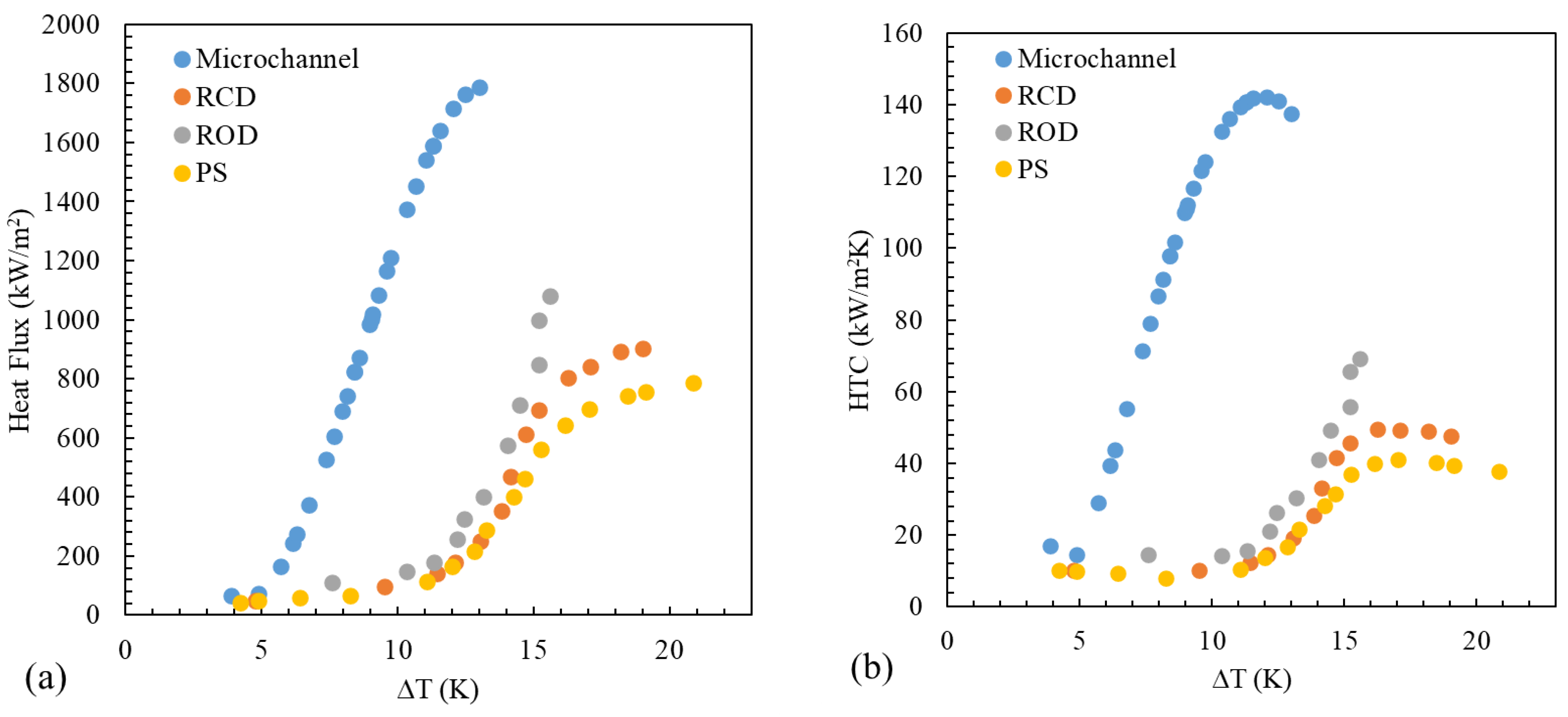
| Surface Type | ) | ∆T (°C) | HTC (kW/m2 K) | CHF (W/m2) |
|---|---|---|---|---|
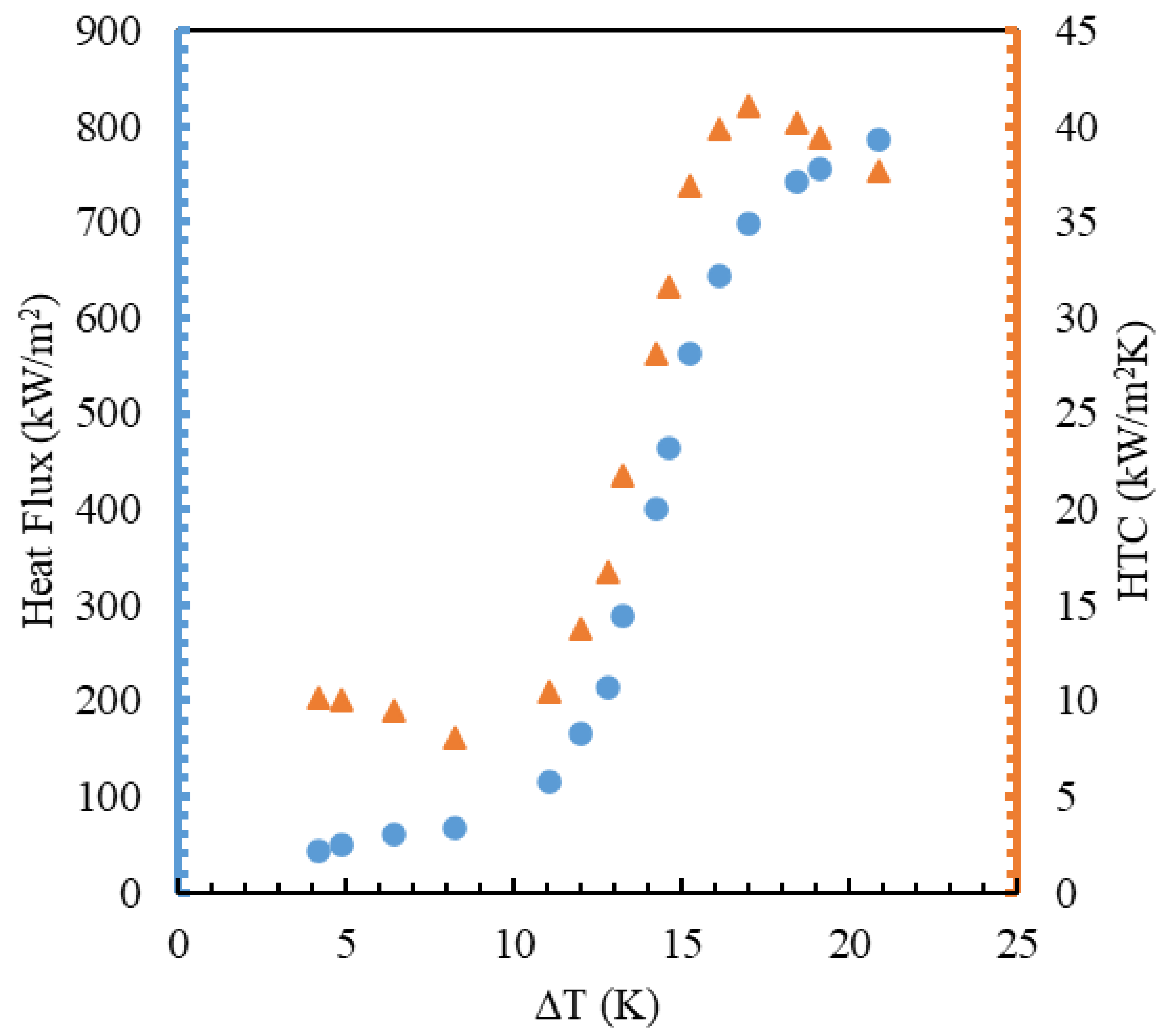
| PS | 0.06 | 20.23 | 44.5 | 791,060 |
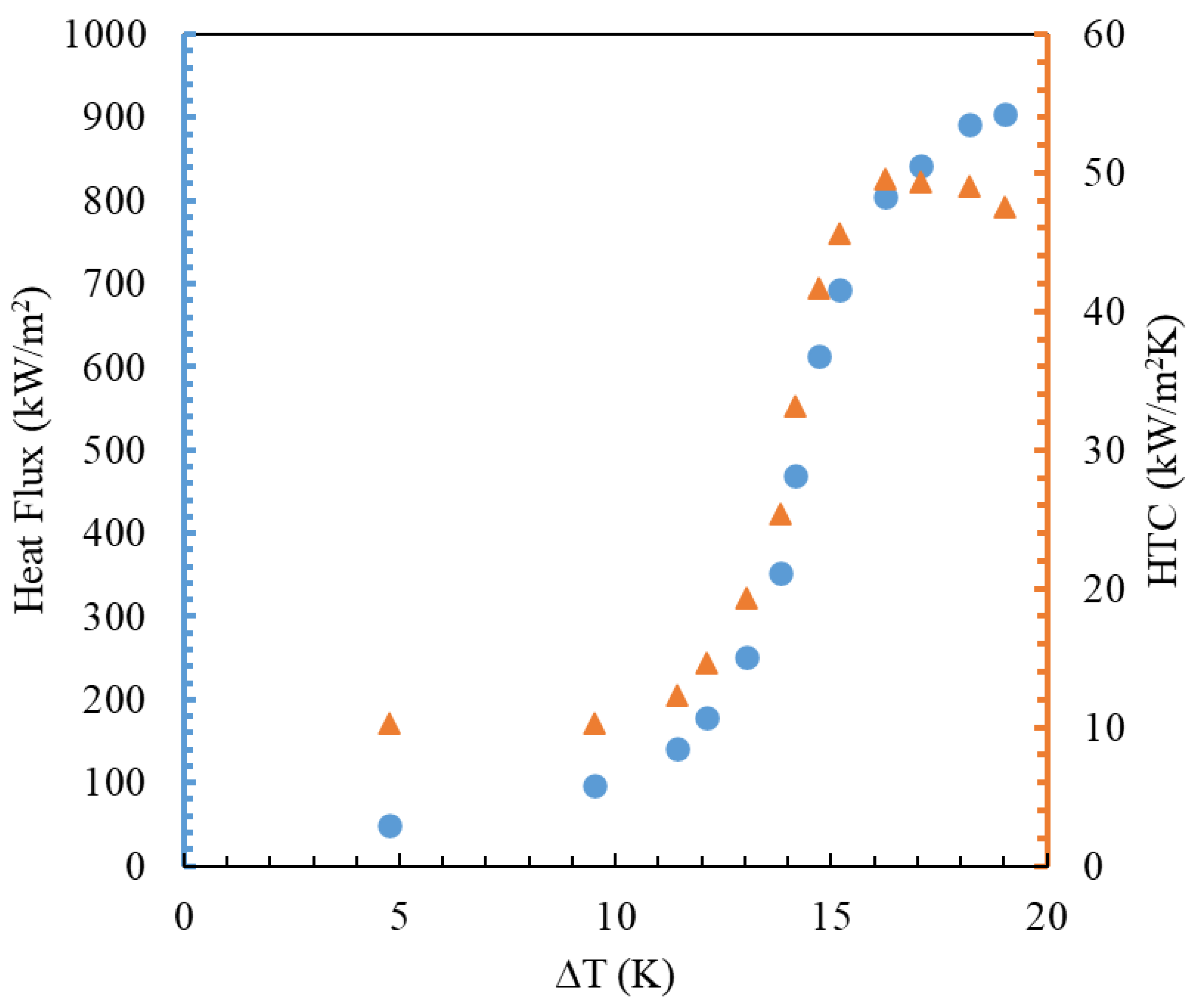
| RCD | 0.170 | 18.84 | 53.2 | 903,746.7 |
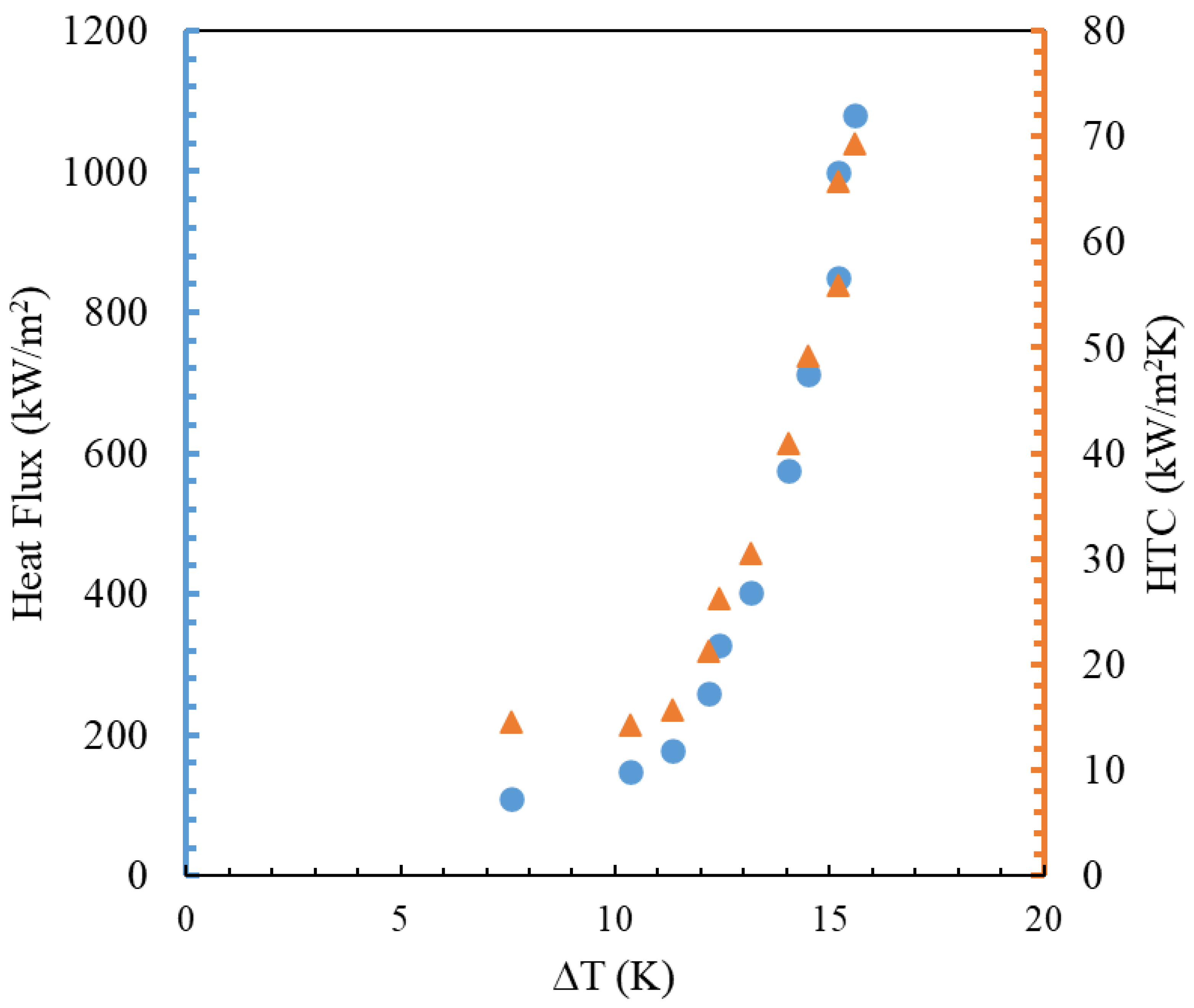
| ROD | 0.116 | 16.97 | 70.4 | 1,094,243 |
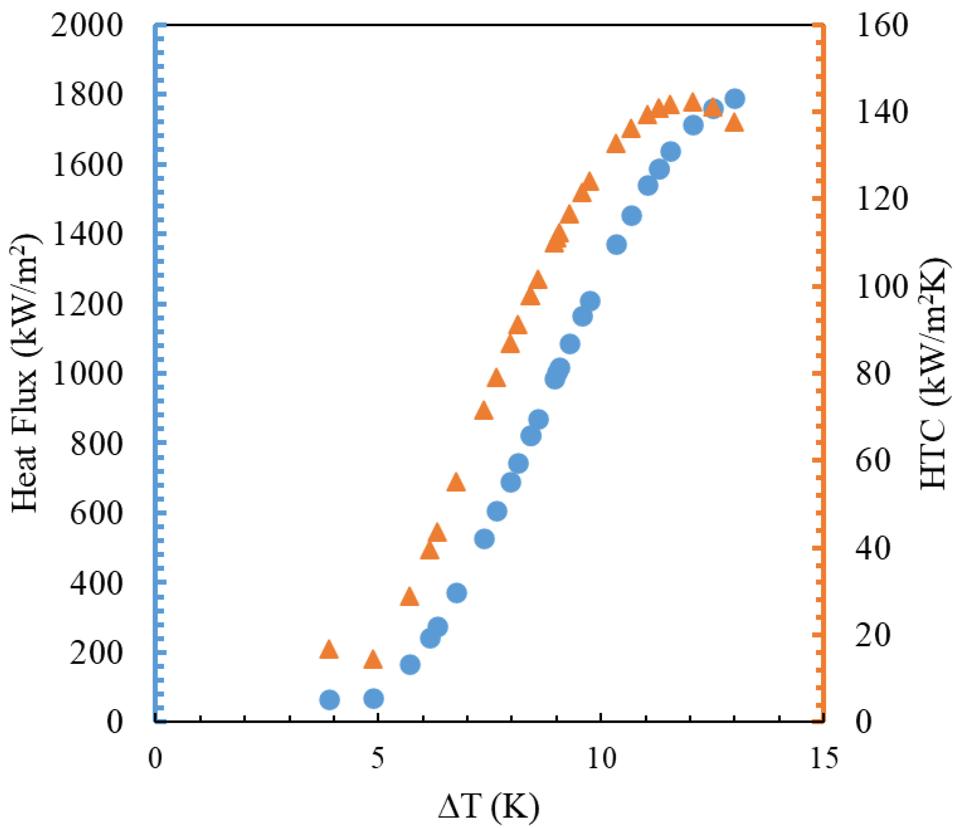
| Microchannel | - | 13.02 | 141.6 | 1,825,798 |
Disclaimer/Publisher’s Note: The statements, opinions and data contained in all publications are solely those of the individual author(s) and contributor(s) and not of MDPI and/or the editor(s). MDPI and/or the editor(s) disclaim responsibility for any injury to people or property resulting from any ideas, methods, instructions or products referred to in the content. |
© 2024 by the author. Licensee MDPI, Basel, Switzerland. This article is an open access article distributed under the terms and conditions of the Creative Commons Attribution (CC BY) license (https://creativecommons.org/licenses/by/4.0/).
Share and Cite
Ali, B.M. An Experimental Study of Heat Transfer in Pool Boiling to Investigate the Effect of Surface Roughness on Critical Heat Flux. ChemEngineering 2024, 8, 44. https://doi.org/10.3390/chemengineering8020044
Ali BM. An Experimental Study of Heat Transfer in Pool Boiling to Investigate the Effect of Surface Roughness on Critical Heat Flux. ChemEngineering. 2024; 8(2):44. https://doi.org/10.3390/chemengineering8020044
Chicago/Turabian StyleAli, Bashar Mahmood. 2024. "An Experimental Study of Heat Transfer in Pool Boiling to Investigate the Effect of Surface Roughness on Critical Heat Flux" ChemEngineering 8, no. 2: 44. https://doi.org/10.3390/chemengineering8020044
APA StyleAli, B. M. (2024). An Experimental Study of Heat Transfer in Pool Boiling to Investigate the Effect of Surface Roughness on Critical Heat Flux. ChemEngineering, 8(2), 44. https://doi.org/10.3390/chemengineering8020044