
3D Printed Surgical Guide for Coronary Artery Bypass Graft: Workflow from Computed Tomography to Prototype

 , , ,
, , ,  and
and 
Abstract
:
1. Introduction
2. Materials and Methods
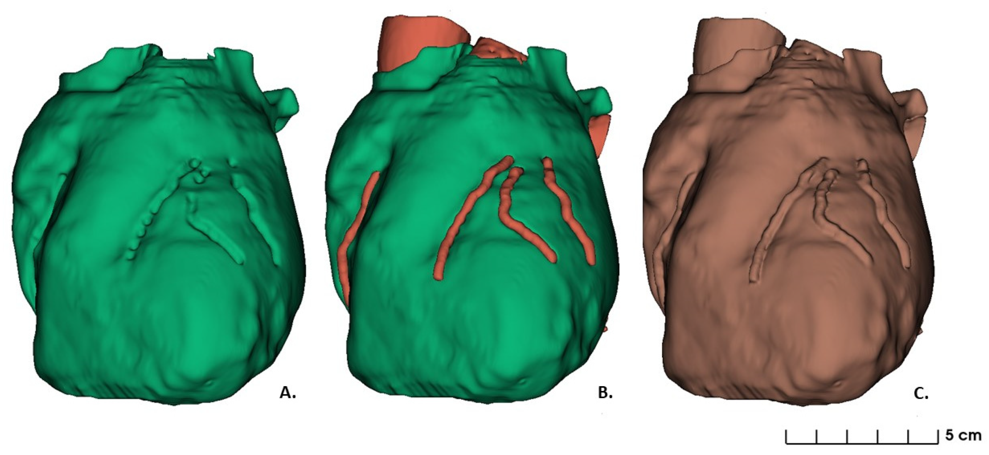
2.1. Data Acquisition and Images Segmentation: 3D Heart Model Design
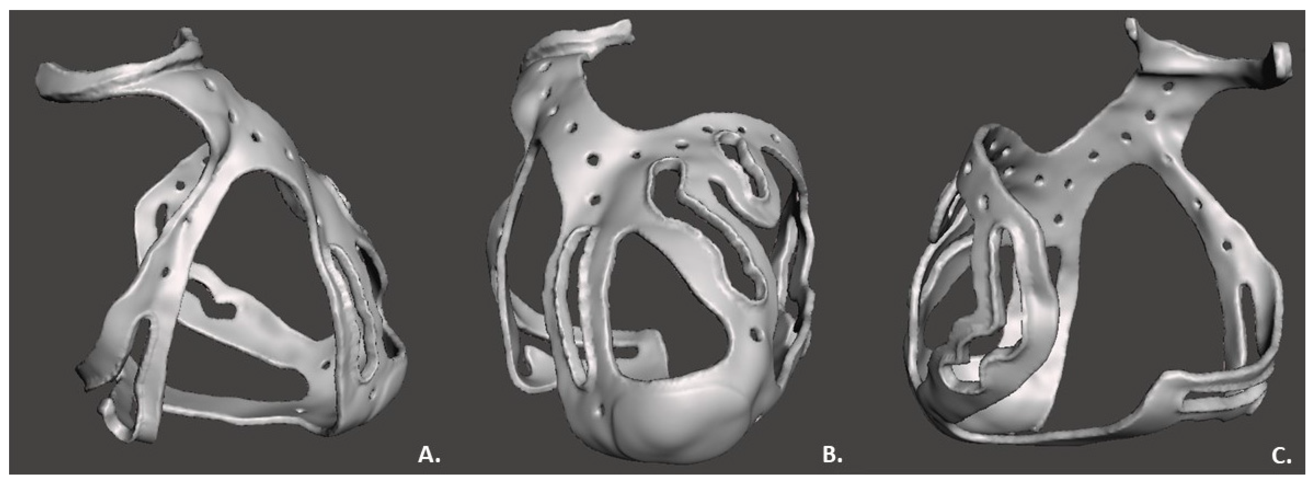
2.2. 3D Surgical Prototype Design
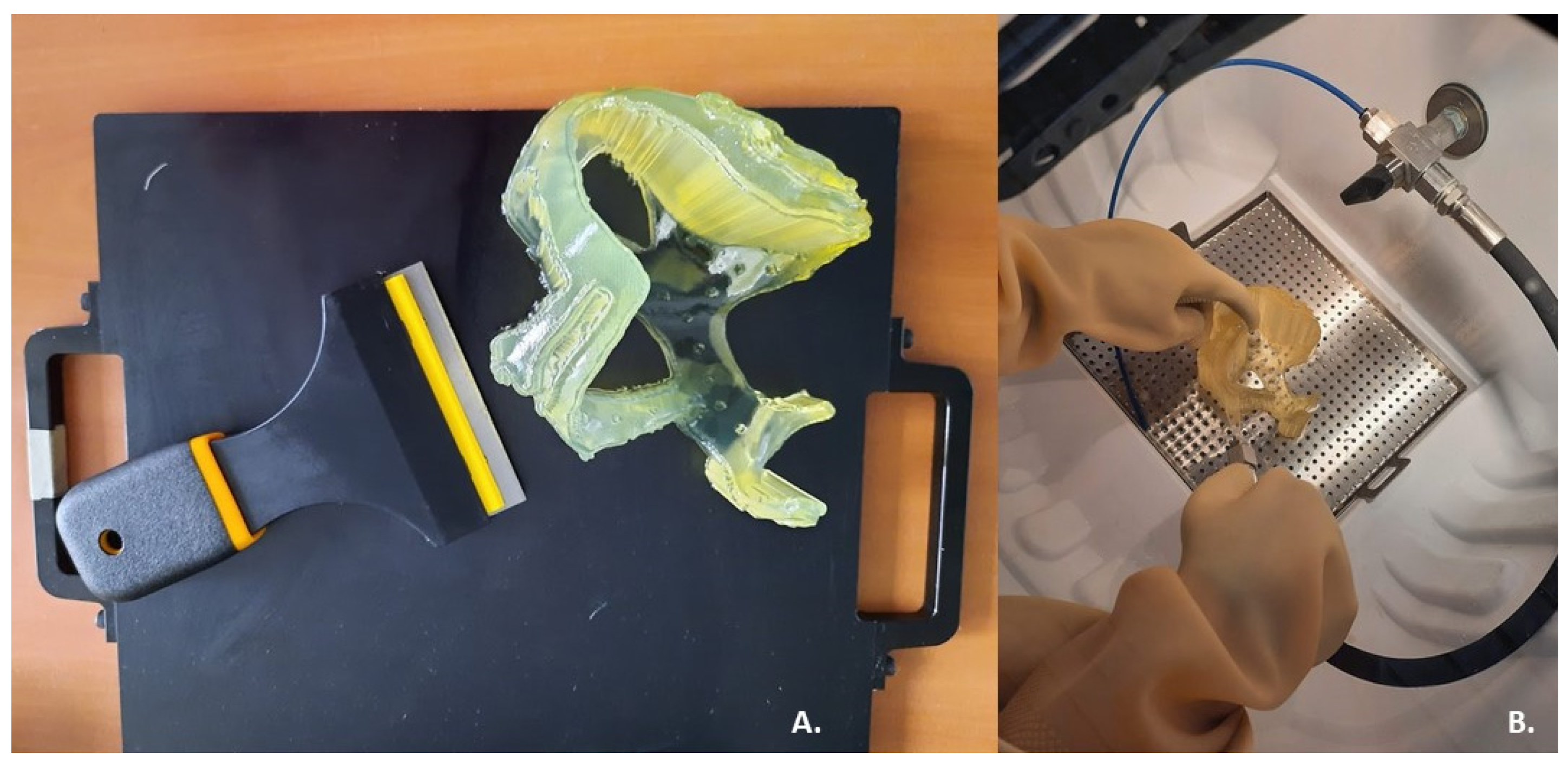
2.3. 3D Printing
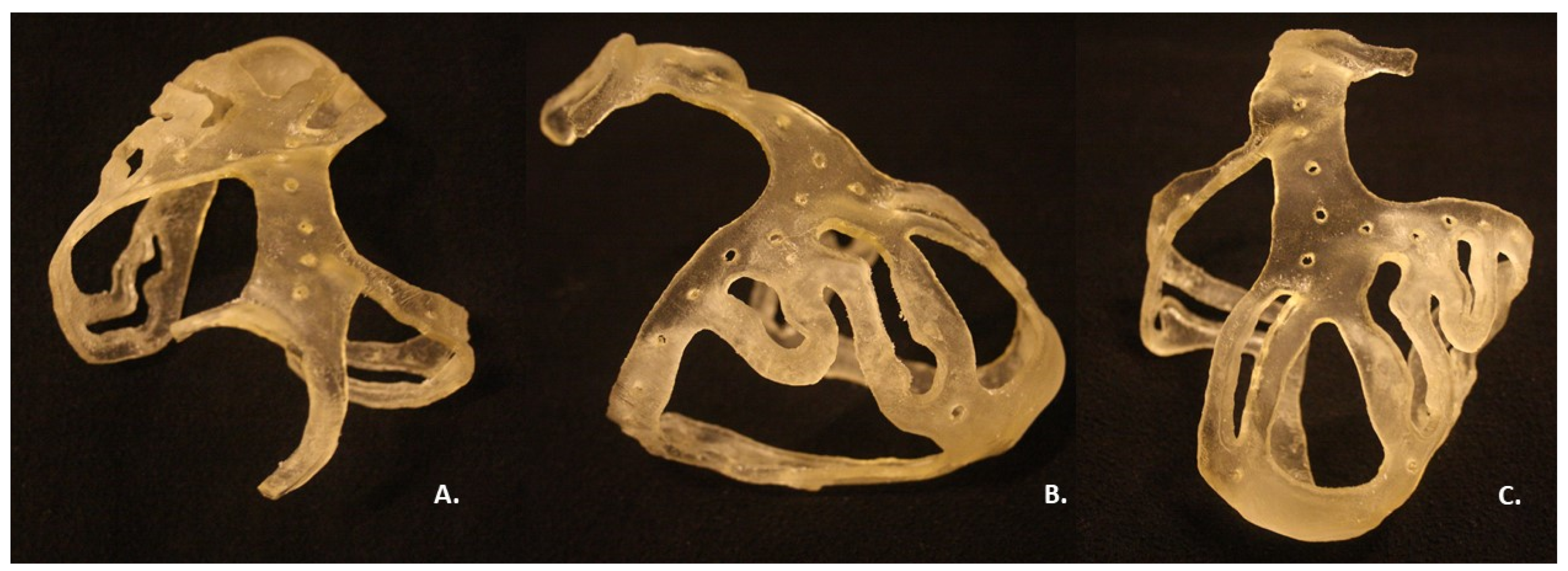
3. Results
4. Discussion
4.1. Feasibility of a 3D Surgical Guide Printing
4.2. Clinical Perspective
Author Contributions
Funding
Institutional Review Board Statement
Informed Consent Statement
Data Availability Statement
Conflicts of Interest
References
- Schmauss, D.; Haeberle, S.; Hagl, C.; Sodian, R. Three-dimensional printing in cardiac surgery and interventional cardiology: A single-centre experience. Eur. J. Cardio-Thorac. Surg. 2014, 47, 1044–1052. [Google Scholar] [CrossRef] [PubMed] [Green Version]
- Bertolini, M.; Rossoni, M.; Colombo, G. Operative Workflow from CT to 3D Printing of the Heart: Opportunities and Challenges. Bioengineering 2021, 8, 130. [Google Scholar] [CrossRef] [PubMed]
- Zhonghua, N.G.; Curtise, K.C.; Andrew, S. Synchrotron radiation computed tomography assessment of calcified plaques and coronary stenosis with different slice thicknesses and beam energies on 3D printed coronary models. Quant. Imaging Med. Surg. 2019, 9, 6. [Google Scholar]
- Giannopoulos, A.A.; Steigner, M.L.; George, E.; Barile, M.; Hunsaker, A.R.; Rybicki, F.J.; Mitsouras, D. Cardiothoracic Applications of 3-dimensional Printing. J. Thorac. Imaging 2016, 31, 253–272. [Google Scholar] [CrossRef] [PubMed] [Green Version]
- Segaran, N.; Saini, G.; Mayer, J.; Naidu, S.; Patel, I.; Alzubaidi, S.; Oklu, R. Application of 3D Printing in Preoperative Planning. J. Clin. Med. 2021, 10, 917. [Google Scholar] [CrossRef] [PubMed]
- Ma, L.; Zhou, Y.; Lin, Z.; Wang, Y.; Zhang, Y.; Xia, H.; Mao, C. 3D-printed guiding templates for improved osteosarcoma resection. Sci. Rep. 2016, 6, 23335. [Google Scholar] [CrossRef] [PubMed]
- Boštjan, V.; Miran, B.; Jože, B. Use of PolyJet technology in manufacture of new product. J. Achiev. Mater. Manuf. Eng. 2006, 18, 319–322. [Google Scholar]
- Stratasys Ltd. Biocompatible. 2020. Available online: https://www.stratasys.com/materials/search/biocompatible (accessed on 7 August 2020).
- Sun, Z.; Lau, I.; Wong, Y.H.; Yeong, C.H. Personalized Three-Dimensional Printed Models in Congenital Heart Disease. J. Clin. Med. 2019, 8, 522. [Google Scholar] [CrossRef] [PubMed] [Green Version]
- Sun, Z. Clinical Applications of Patient-Specific 3D Printed Models in Cardiovascular Disease: Current Status and Future Directions. Biomolecules 2020, 10, 1577. [Google Scholar] [CrossRef] [PubMed]


Publisher’s Note: MDPI stays neutral with regard to jurisdictional claims in published maps and institutional affiliations. |
© 2022 by the authors. Licensee MDPI, Basel, Switzerland. This article is an open access article distributed under the terms and conditions of the Creative Commons Attribution (CC BY) license (https://creativecommons.org/licenses/by/4.0/).
Share and Cite
Cappello, I.A.; Candelari, M.; Pannone, L.; Monaco, C.; Bori, E.; Talevi, G.; Ramak, R.; La Meir, M.; Gharaviri, A.; Chierchia, G.B.; et al. 3D Printed Surgical Guide for Coronary Artery Bypass Graft: Workflow from Computed Tomography to Prototype. Bioengineering 2022, 9, 179. https://doi.org/10.3390/bioengineering9050179
Cappello IA, Candelari M, Pannone L, Monaco C, Bori E, Talevi G, Ramak R, La Meir M, Gharaviri A, Chierchia GB, et al. 3D Printed Surgical Guide for Coronary Artery Bypass Graft: Workflow from Computed Tomography to Prototype. Bioengineering. 2022; 9(5):179. https://doi.org/10.3390/bioengineering9050179
Chicago/Turabian StyleCappello, Ida Anna, Mara Candelari, Luigi Pannone, Cinzia Monaco, Edoardo Bori, Giacomo Talevi, Robbert Ramak, Mark La Meir, Ali Gharaviri, Gian Battista Chierchia, and et al. 2022. "3D Printed Surgical Guide for Coronary Artery Bypass Graft: Workflow from Computed Tomography to Prototype" Bioengineering 9, no. 5: 179. https://doi.org/10.3390/bioengineering9050179
APA StyleCappello, I. A., Candelari, M., Pannone, L., Monaco, C., Bori, E., Talevi, G., Ramak, R., La Meir, M., Gharaviri, A., Chierchia, G. B., Innocenti, B., & de Asmundis, C. (2022). 3D Printed Surgical Guide for Coronary Artery Bypass Graft: Workflow from Computed Tomography to Prototype. Bioengineering, 9(5), 179. https://doi.org/10.3390/bioengineering9050179