
Development of Bionic Semicircular Canals and the Sensation of Angular Acceleration


Abstract
:
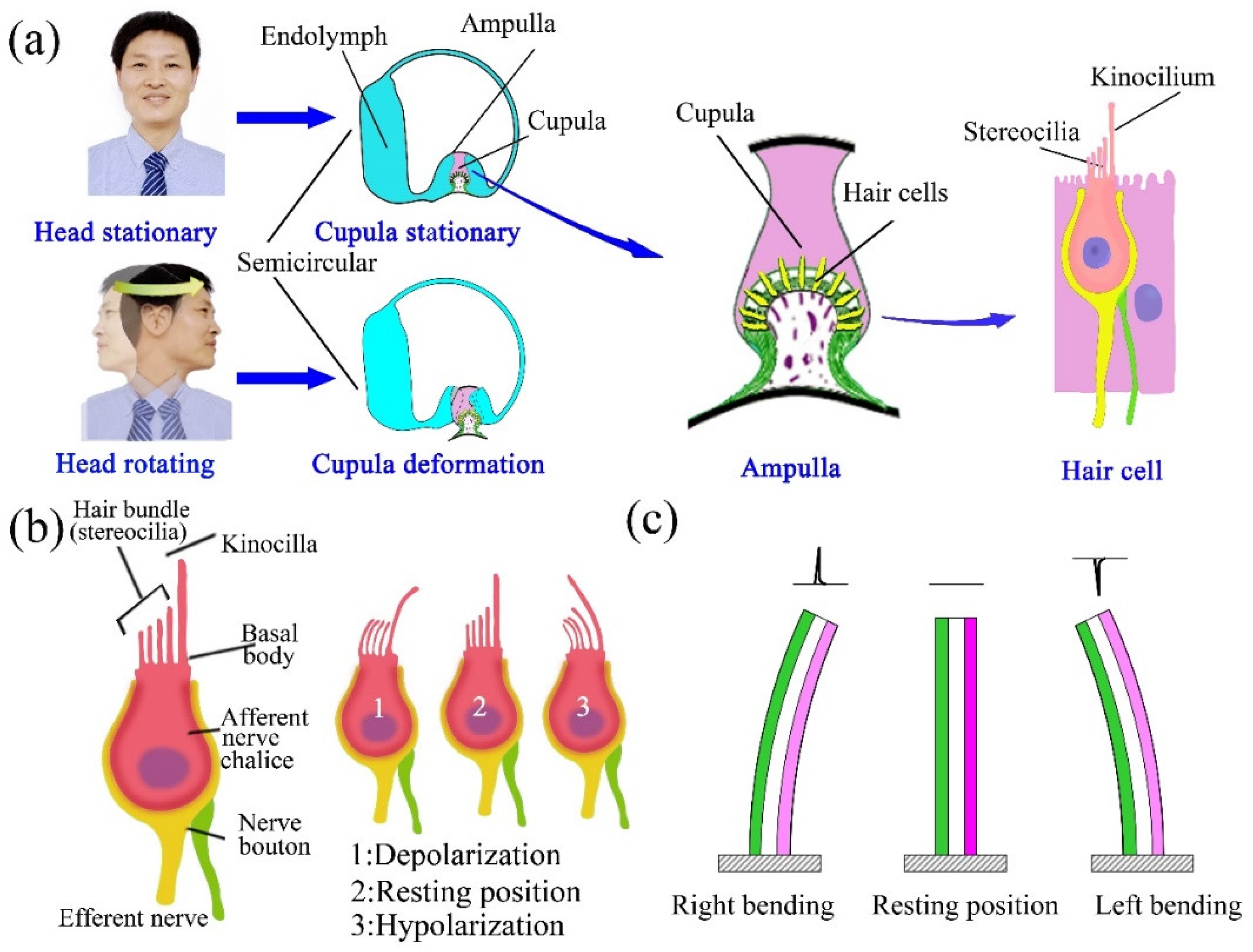
1. Introduction
2. Materials and Methods
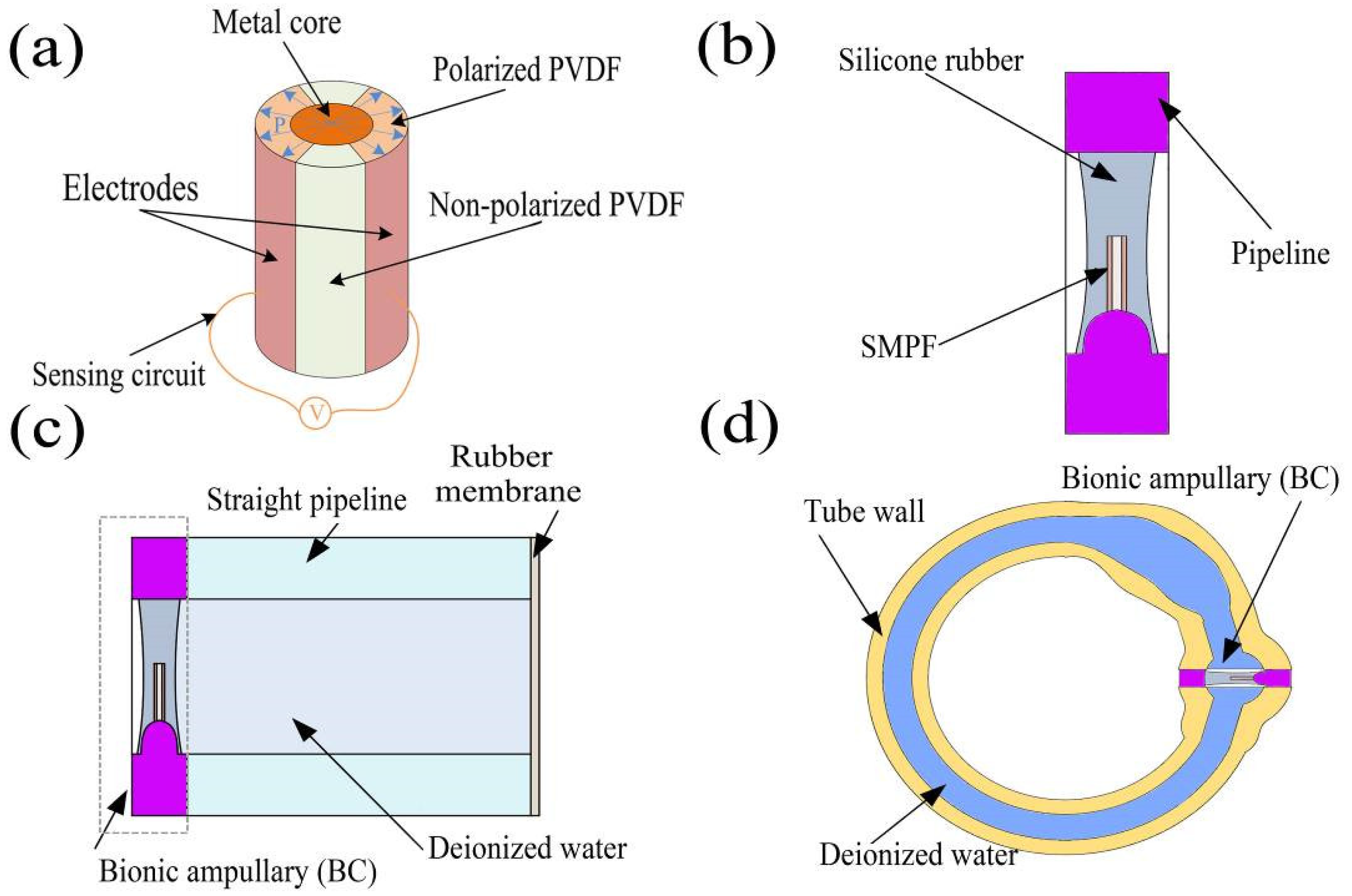
2.1. Materials 12
2.2. Fabrication Methods
2.2.1. Preparation of the SMPF
2.2.2. Preparation of the BA
2.2.3. Preparation of the Straight Semicircular Canal
2.2.4. Preparation of the 1-BSC and 3BSC
2.3. The Experimental Methods
2.3.1. The Straight Pipeline Semicircular Canal Experiment
2.3.2. 1-BSC Experiment
2.3.3. 3-BSC Experiment
2.3.4. Experimental Data Collection
3. Results and Discussion
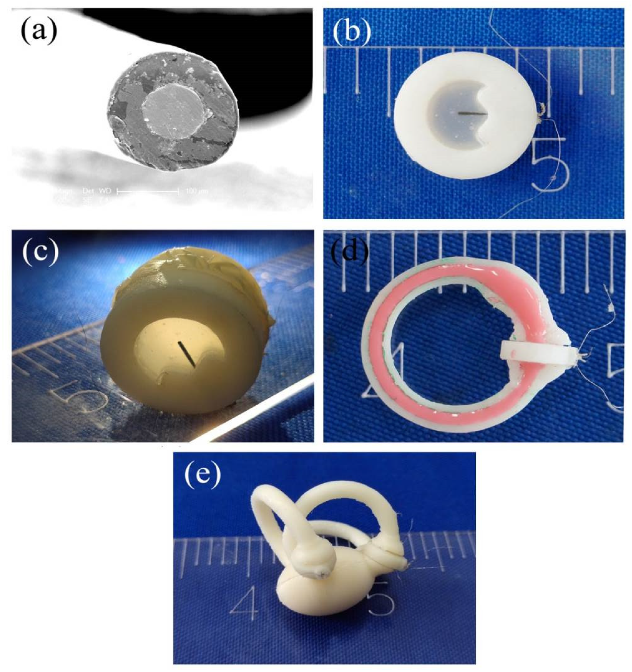
3.1. The Micro- and Macrostructures of Production
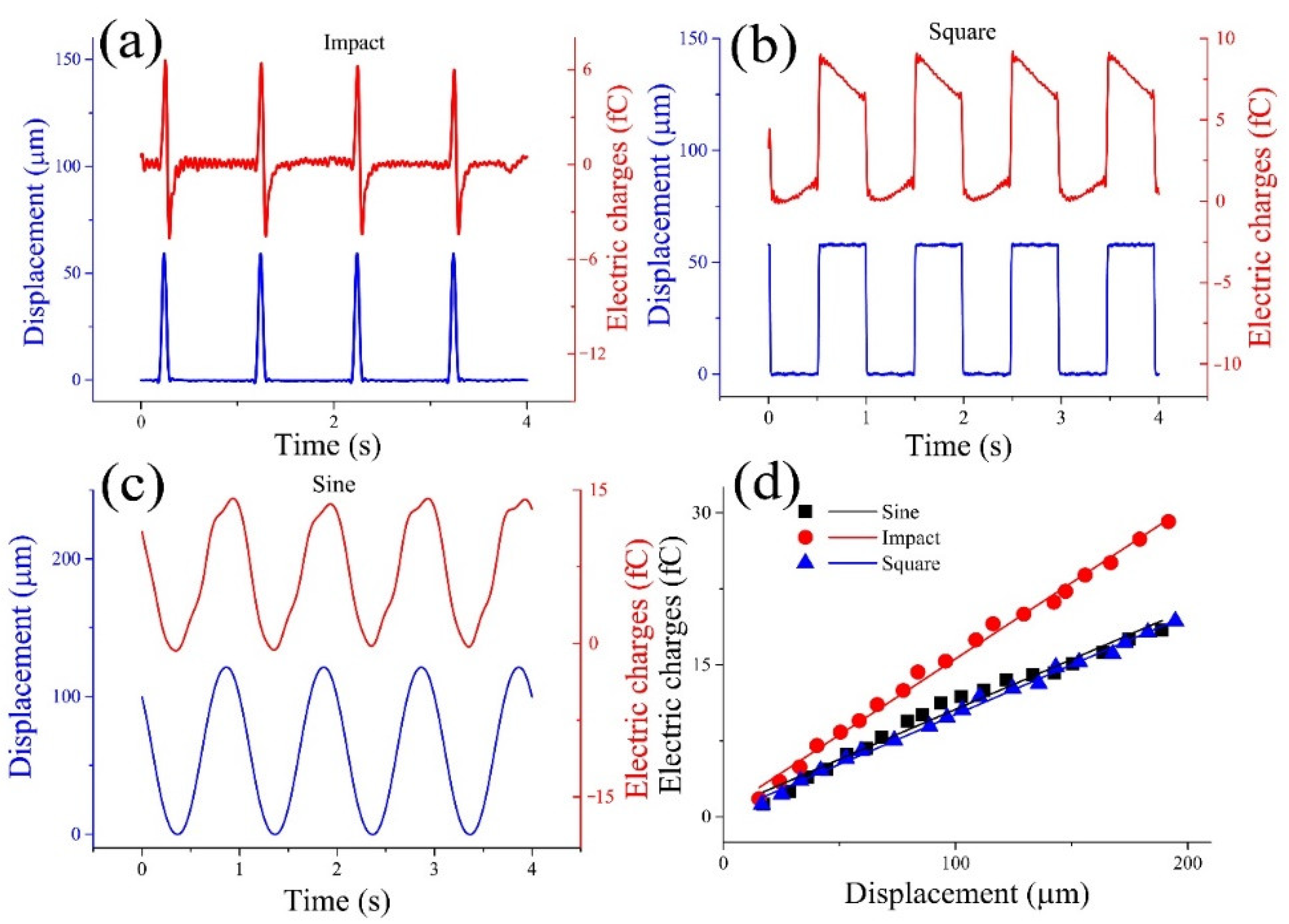
3.2. The Results of the Straight Semicircular Canal Experiments
3.3. The Results of the 1-BSC Experiments
3.4. The Results of the 3-BSC Experiments
4. Conclusions
Supplementary Materials
Author Contributions
Funding
Institutional Review Board Statement
Informed Consent Statement
Data Availability Statement
Conflicts of Interest
References
- Rabbitt, R.D. Semicircular canal biomechanics in health and disease. J. Neurophysiol. 2019, 121, 732–755. [Google Scholar] [CrossRef] [PubMed] [Green Version]
- Desai, S.S.; Ali, H.; Lysakowski, A. Comparative morphology of rodent vestibular periphery. II. Cristae ampullares. J. Neurophysiol. 2005, 93, 267–280. [Google Scholar] [CrossRef] [PubMed] [Green Version]
- Deng, X.; Wagner, H.-J.; Popper, A.N. The Inner Ear and its Coupling to the Swim Bladder in the Deep-Sea Fish Antimora rostrata (Teleostei: Moridae). Deep Sea Res. Part 1 Oceanogr. Res. Pap. 2010, 58, 27–37. [Google Scholar] [CrossRef] [PubMed] [Green Version]
- Köppl, C.; Wilms, V.; Russell, I.J.; Nothwang, H.G. Evolution of Endolymph Secretion and Endolymphatic Potential Generation in the Vertebrate Inner Ear. Brain Behav. Evol. 2018, 92, 1–31. [Google Scholar] [CrossRef]
- Fisher, J.A.N.; Kowalik, L.; Hudspeth, A.J. Imaging electrical resonance in hair cells. Proc. Natl. Acad. Sci. USA 2010, 108, 1651–1656. [Google Scholar] [CrossRef] [Green Version]
- Lueck, C.J. Clinical neurophysiology of the vestibular system. Neuromuscul. Disord. 2011, 12, 995. [Google Scholar] [CrossRef]
- Rabbitt, R.D.; Brichta, A.M.; Tabatabaee, H.; Boutros, P.J.; Ahn, J.H.; Della Santina, C.C.; Poppi, L.A.; Lim, R. Heat pulse excitability of vestibular hair cells and afferent neurons. J. Neurophysiol. 2016, 116, 825–843. [Google Scholar] [CrossRef] [Green Version]
- Selva, P.; Oman, C.M.; Stone, H.A. Mechanical properties and motion of the cupula of the human semicircular canal. J. Vestib. Res. Equilib. Orientat. 2009, 19, 95–110. [Google Scholar] [CrossRef]
- McLaren, J.W.; Hillman, D.E. Displacement of the semicircular canal cupula during sinusoidal rotation. Neuroscience 1979, 4, 2001–2008. [Google Scholar] [CrossRef]
- Shen, S.; Zhao, F.; Chen, Z.; Yu, S.; Cao, T.; Ma, P.; Zheng, Q.Y. Biomechanical Analysis of Angular Motion in Association with Bilateral Semicircular Canal Function. Biophys. J. 2020, 118, 729–741. [Google Scholar] [CrossRef]
- Obrist, D.; Hegemann, S.; Kronenberg, D.; Häuselmann, O.; Rösgen, T. In vitro model of a semicircular canal: Design and validation of the model and its use for the study of canalithiasis. J. Biomech. 2010, 43, 1208–1214. [Google Scholar] [CrossRef] [PubMed] [Green Version]
- Santos, C.F.; Belinha, J.; Gentil, F.; Parente, M.; Jorge, R.N. An alternative 3D numerical method to study the biomechanical behaviour of the human inner ear semicircular canal. Acta Bioeng. Biomech. 2017, 19, 3–15. [Google Scholar] [PubMed]
- Guyot, J.P.; Perezs, F.A.; Guinand, N.; Berg, R.; Stokroos, R.; Kingma, H. Vestibular assistance systems: Promises and challenges. J. Neurol. 2016, 263, 30–35. [Google Scholar] [CrossRef] [PubMed] [Green Version]
- Shkel, A.M.; Zeng, F.G. An electronic prosthesis mimicking the dynamic vestibular function. Audiol. Neurotol. 2005, 11, 113–122. [Google Scholar] [CrossRef] [PubMed] [Green Version]
- Obrist, D. Flow Phenomena in the Inner Ear. Annu. Rev. Fluid Mech. 2019, 51, 487–510. [Google Scholar] [CrossRef]
- Wu, X.; Yu, S.; Shen, S.; Liu, W. Quantitative analysis of the biomechanical response of semicircular canals and nystagmus under different head positions. Hear. Res. 2021, 407, 108282. [Google Scholar] [CrossRef]
- Angelaki, D.E.; Cullen, K.E. Vestibular system: The many facets of a multimodal sense. Annu. Rev. Neurosci. 2008, 31, 125–150. [Google Scholar] [CrossRef] [Green Version]
- Raoufi, M.A.; Moshizi, S.A.; Razmjou, A.; Wu, S.; Warkiani, M.E.; Asadnia, M. Development of a Biomimetic Semicircular Canal with MEMS Sensors to Restore Balance. IEEE Sens. J. 2019, 19, 11675–11686. [Google Scholar] [CrossRef]
- Abolpour, M.S.; Azadi, S.; Belford, A.; Razmjou, A.; Wu, S.; Han, Z.J.; Asadnia, M. Development of an Ultra-Sensitive and Flexible Piezoresistive Flow Sensor Using Vertical Graphene Nanosheets. Nano Micro Lett. 2020, 12, 1–18. [Google Scholar] [CrossRef]
- Gong, W.; Merfeld, D.M. System Design and Performance of a Unilateral Horizontal Semicircular Canal Prosthesis. IEEE Trans. Biomed. Eng. 2002, 49, 175–181. [Google Scholar] [CrossRef]
- Bian, Y.; Liu, R.; Hui, S. Fabrication of a polyvinylidene difluoride fiber with a metal core and its application as directional air flow sensor. Funct. Mater. Lett. 2016, 9, 1–5. [Google Scholar] [CrossRef]
- Bian, Y.; Liu, R.; Huang, X.; Hong, J.; Huang, H.; Hui, S. Design and fabrication of a metal core PVDF fiber for an air flow sensor. Smart Mater. Struct. 2015, 24, 105001. [Google Scholar] [CrossRef]
- Schubert, M.C.; Minor, L.B. Vestibulo-ocular Physiology Underlying Vestibular Hypofunction. Phys. Ther. 2004, 84, 373–385. [Google Scholar] [CrossRef] [PubMed]
- Carey, J.P.; Santina Della, C.C. Principles of Applied Vestibular Physiology Cummings. Otolaryngol. Head Neck Surg. 2010, 2276–2304. [Google Scholar]
- Kondrachuk, A.V. Computer simulation of the mechanical stimulation of the saccular membrane of bullfrog. Hear. Res. 2000, 143, 130–138. [Google Scholar] [CrossRef]
- Goyens, J.; Pourquie, M.J.B.M.; Poelma, C.; Westerweel, J. Asymmetric cupula displacement due to endolymph vortex in the human semicircular canal. Biomech. Model. Mechanobiol. 2019, 18, 1577–1590. [Google Scholar] [CrossRef] [PubMed] [Green Version]
- Movassat, M. Blast Wave Induced Flows in Semicircular Canals. Am. J. Biosci. Bioeng. 2015, 3, 1. [Google Scholar] [CrossRef]
- Rubin, E. The Relationship between Vertigo, Vestibular System Disorders, and Therapy. Sci. J. Lander Coll. Arts Sci. 2018, 12, 2. [Google Scholar]
- Obrist, D. Fluidmechanics of semicircular canals-Revisited. Z. Angew. Math. Phys. 2008, 59, 475–497. [Google Scholar] [CrossRef] [Green Version]
- Kondrachuk, A.V.; Shipov, A.A.; Astakhova, T.G.; Boyle, R.D. Current trends in mathematical simulation of the function of semicircular canals. Hum. Physiol. 2011, 37, 802–809. [Google Scholar] [CrossRef]
- Selva, P.; Morlier, J.; Gourinat, Y. Development of a dynamic virtual reality model of the inner ear sensory system as a learning and demonstrating tool. Model. Simul. Eng. 2009, 2009, 245606. [Google Scholar] [CrossRef] [Green Version]
- Bradshaw, A.P.; Curthoys, I.S.; Todd, M.J.; Magnussen, J.S.; Taubman, D.S.; Aw, S.T.; Halmagyi, G.M. A mathematical model of human semicircular canal geometry: A new basis for interpreting vestibular physiology. J. Assoc. Res. Otolaryngol. 2010, 11, 145–159. [Google Scholar] [CrossRef] [PubMed] [Green Version]
- Rabbitt, R.D. Directional coding of three-dimensional movements by the vestibular semicircular canals. Biol. Cybern. 1999, 80, 417–431. [Google Scholar] [CrossRef] [PubMed]
- Obrist, D.; Hegemann, S. Fluid-particle dynamics in canalithiasis. J. R. Soc. Interface 2008, 5, 1215–1229. [Google Scholar] [CrossRef] [PubMed] [Green Version]
- Kim, S.-H.; Kim, J. Effects of head position on perception of gravity in vestibular neuritis and lateral medullary infarction. Front. Neurol. 2018, 9, 60. [Google Scholar] [CrossRef] [Green Version]
- Neugebauer, C.A.; Newkirk, J.B.; Vermilyea, D.A.; Bauer, S.H. Structure and Properties of Thin Films. J. Electrochem. Soc. 1966, 109, 29–40. [Google Scholar]

Publisher’s Note: MDPI stays neutral with regard to jurisdictional claims in published maps and institutional affiliations. |
© 2022 by the authors. Licensee MDPI, Basel, Switzerland. This article is an open access article distributed under the terms and conditions of the Creative Commons Attribution (CC BY) license (https://creativecommons.org/licenses/by/4.0/).
Share and Cite
Wang, Z.; Lu, S.; Wang, X.; Chen, Y.; Gong, J.; Jiang, Y.; Bian, Y. Development of Bionic Semicircular Canals and the Sensation of Angular Acceleration. Bioengineering 2022, 9, 180. https://doi.org/10.3390/bioengineering9050180
Wang Z, Lu S, Wang X, Chen Y, Gong J, Jiang Y, Bian Y. Development of Bionic Semicircular Canals and the Sensation of Angular Acceleration. Bioengineering. 2022; 9(5):180. https://doi.org/10.3390/bioengineering9050180
Chicago/Turabian StyleWang, Zhi, Shien Lu, Xianjin Wang, Yuhang Chen, Junjie Gong, Yani Jiang, and Yixiang Bian. 2022. "Development of Bionic Semicircular Canals and the Sensation of Angular Acceleration" Bioengineering 9, no. 5: 180. https://doi.org/10.3390/bioengineering9050180
APA StyleWang, Z., Lu, S., Wang, X., Chen, Y., Gong, J., Jiang, Y., & Bian, Y. (2022). Development of Bionic Semicircular Canals and the Sensation of Angular Acceleration. Bioengineering, 9(5), 180. https://doi.org/10.3390/bioengineering9050180