
Effect of Microwave Radiation on the Properties of Hydrogel, Cork, Perlite, and Ceramsite
 ,
,
Abstract
:1. Introduction
2. Results and Discussion
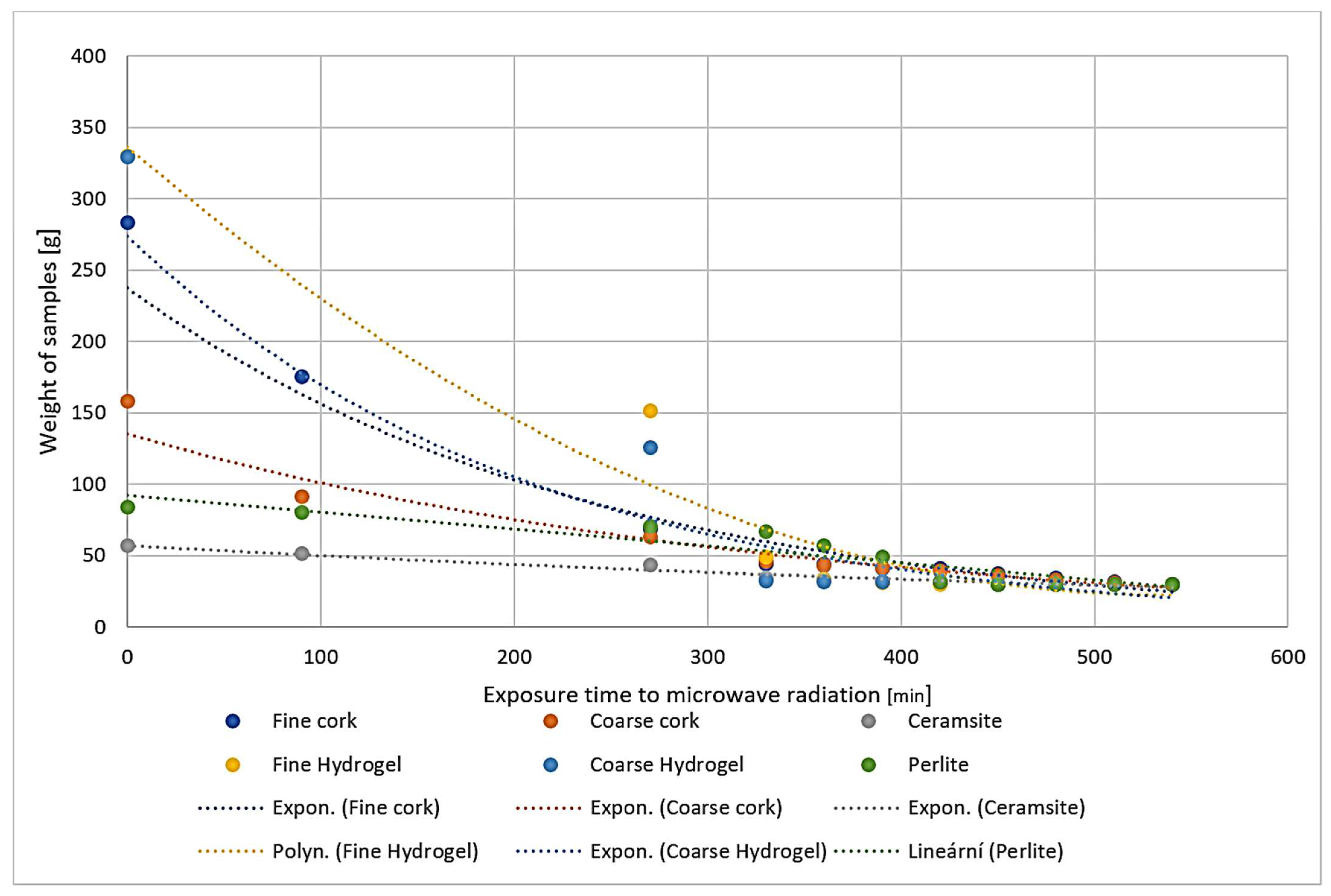
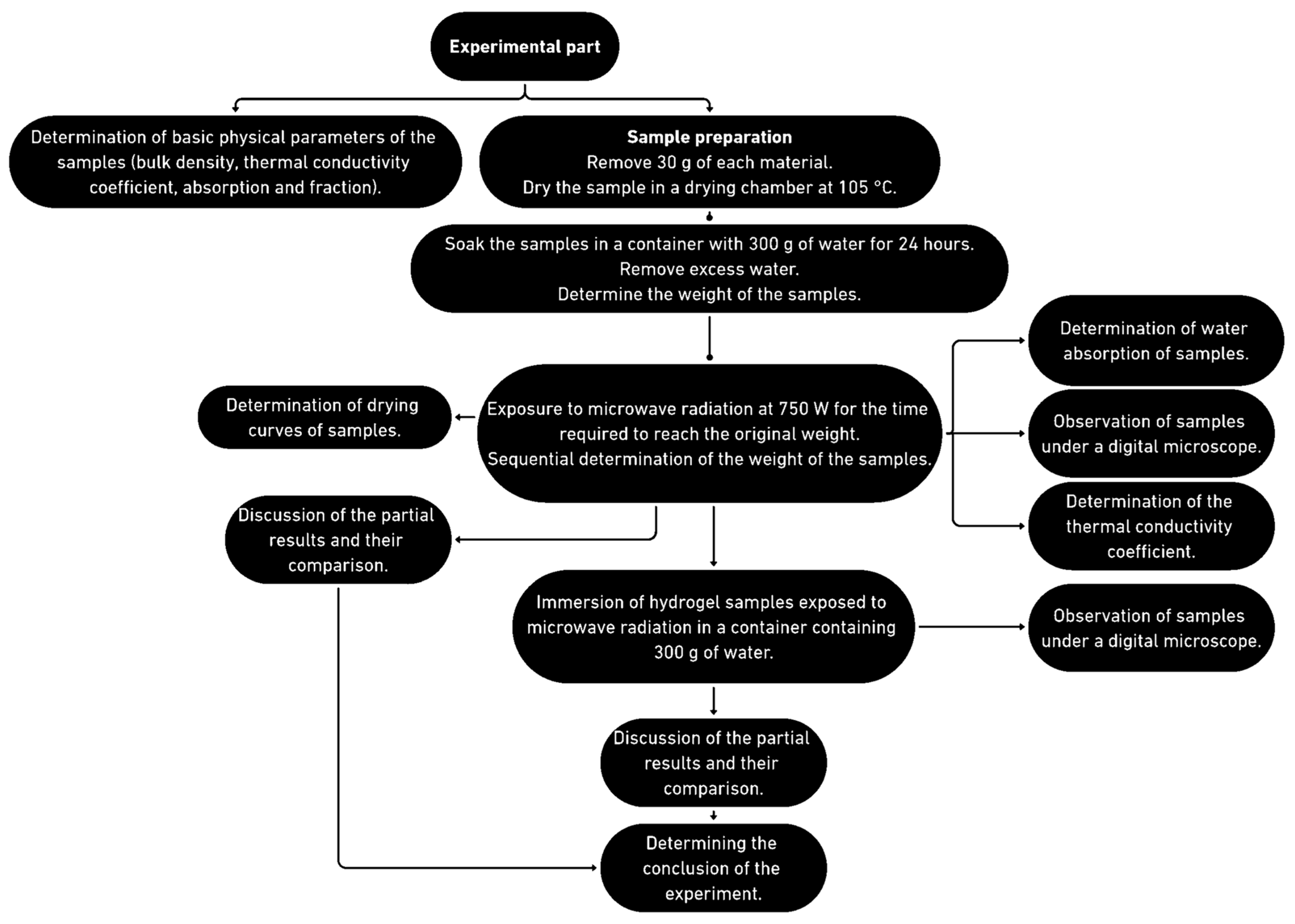
2.1. The Course of the Experiment
2.2. Placement in a Water Bath
2.3. Determination of Bulk Density (ČSN ISO 60 (642101))
2.4. Determination of Water Absorption (ČSN EN ISO 16535 (727056))
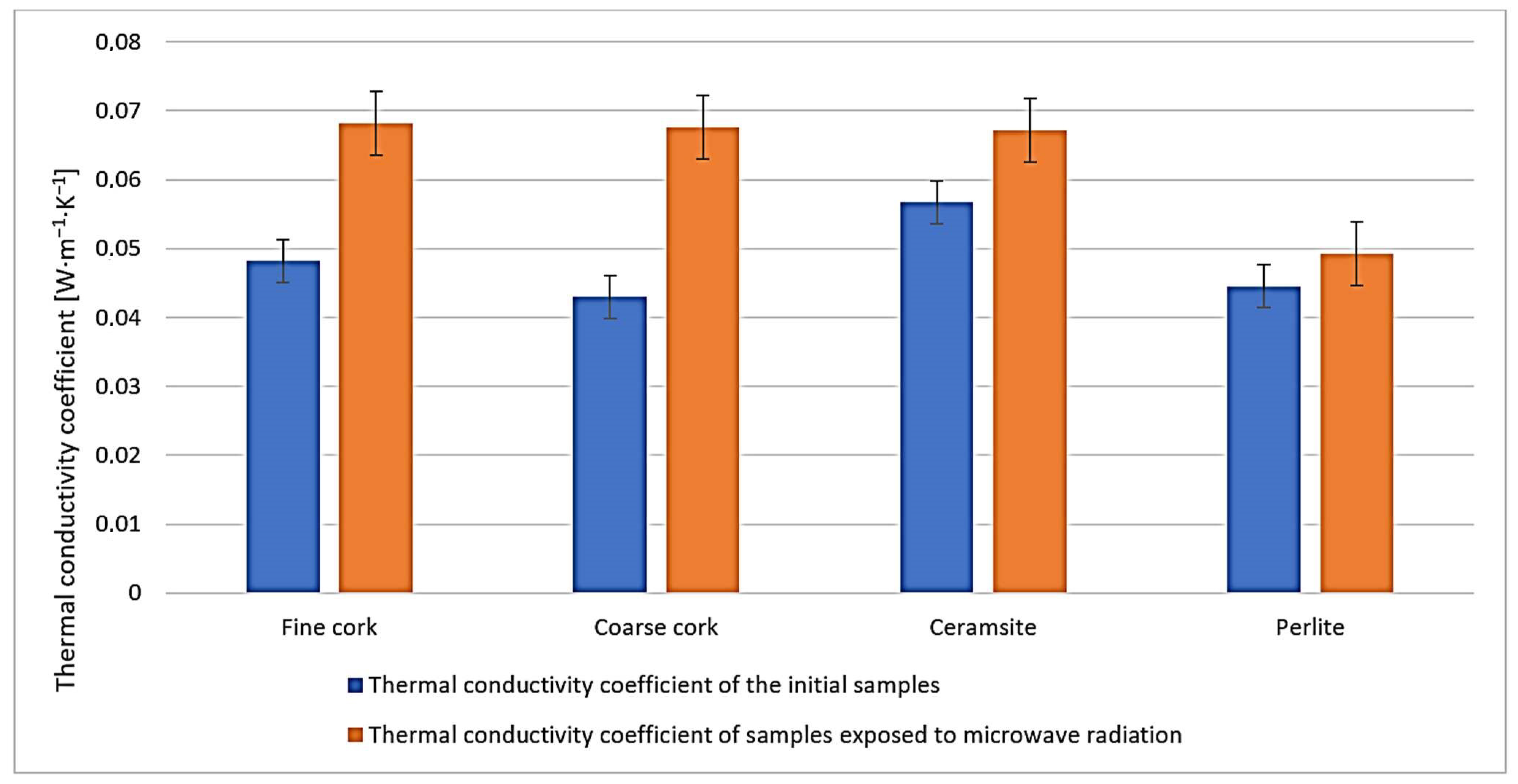
2.5. Determination of the Thermal Conductivity Coefficient (ČSN 72 7306)
3. Conclusions
4. Materials and Methods
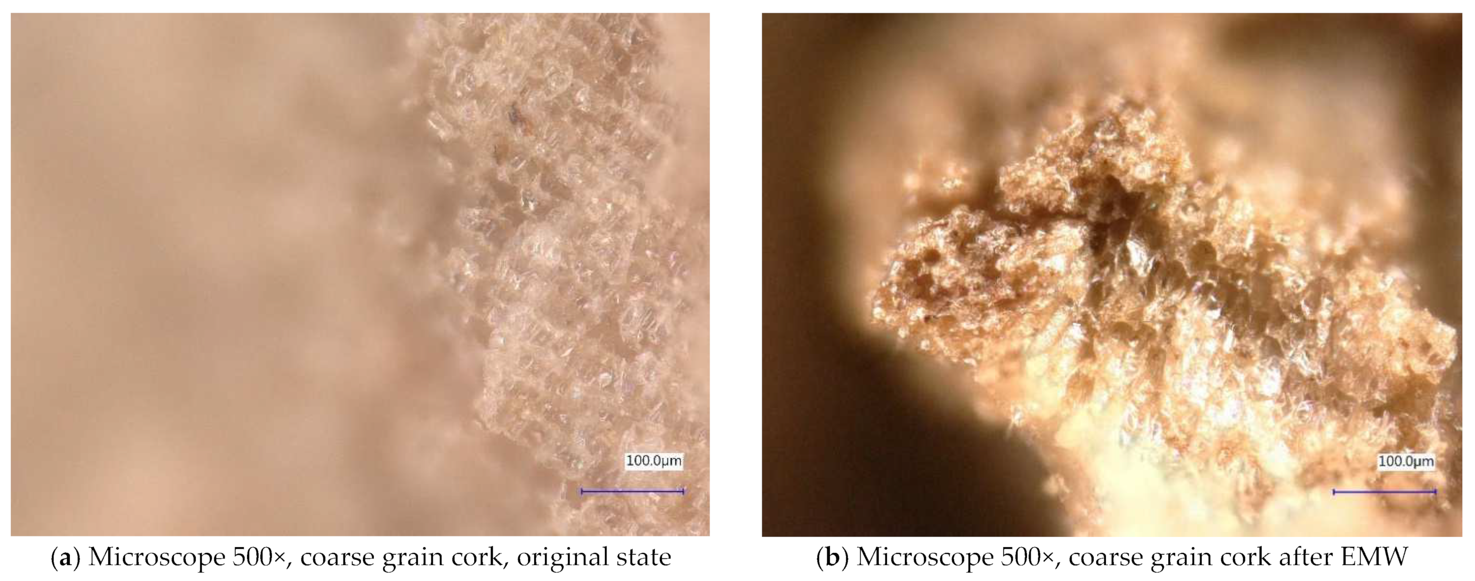
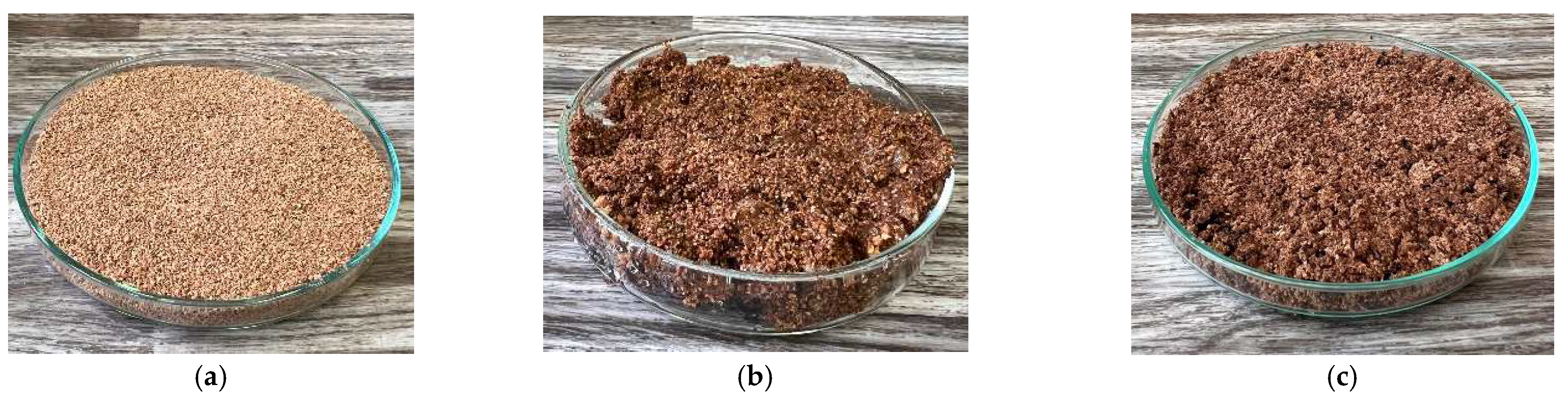
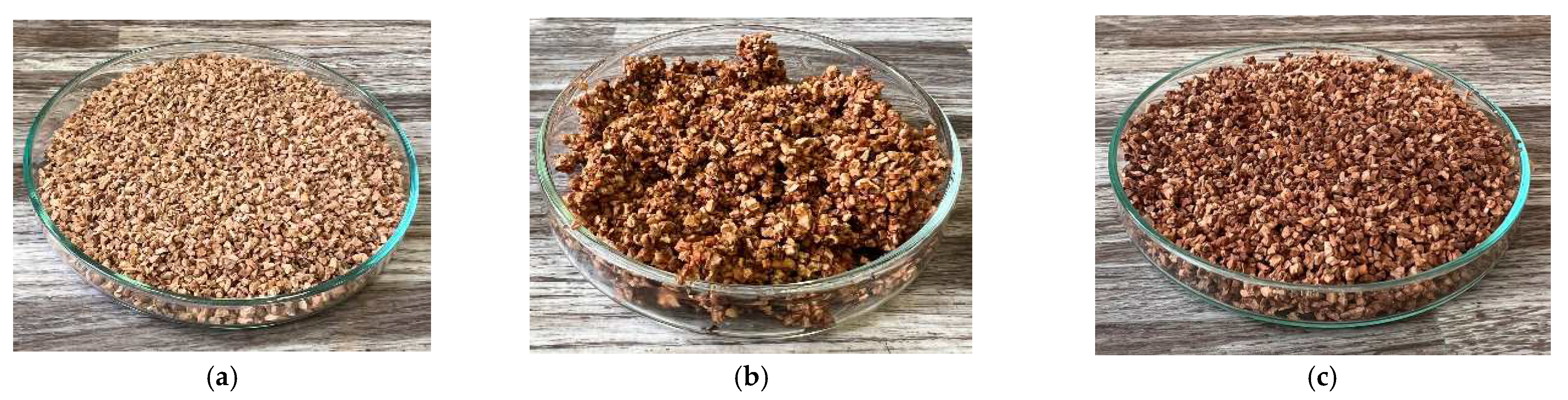
4.1. Cork
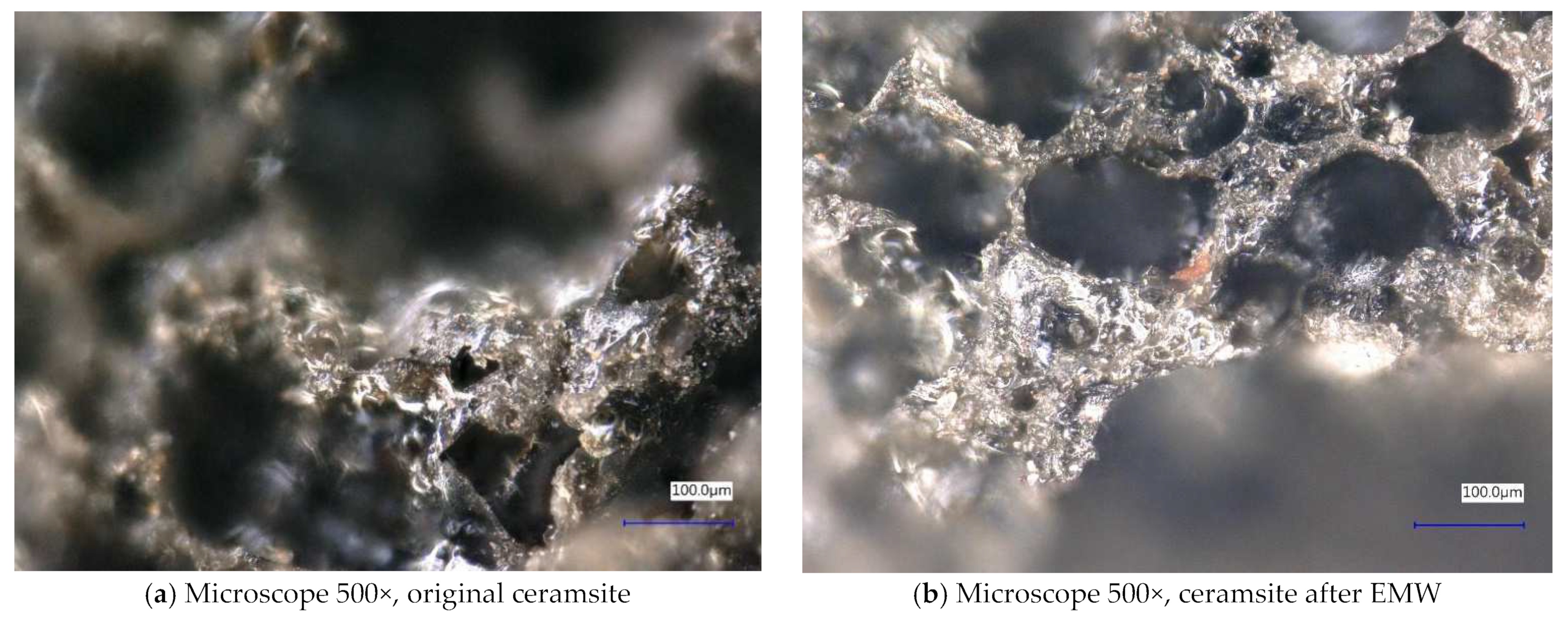
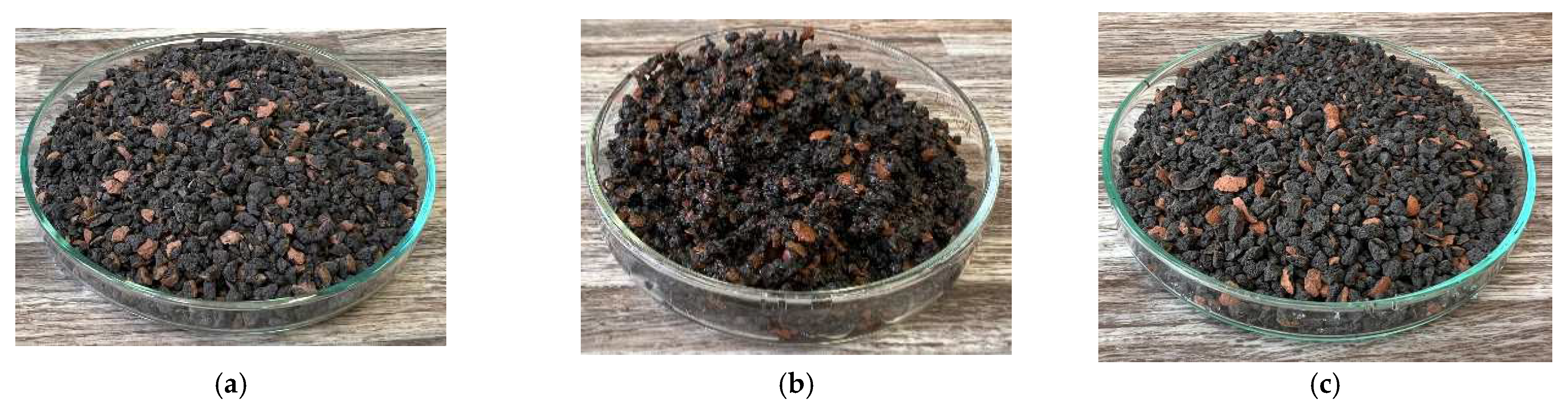
4.2. Ceramsite
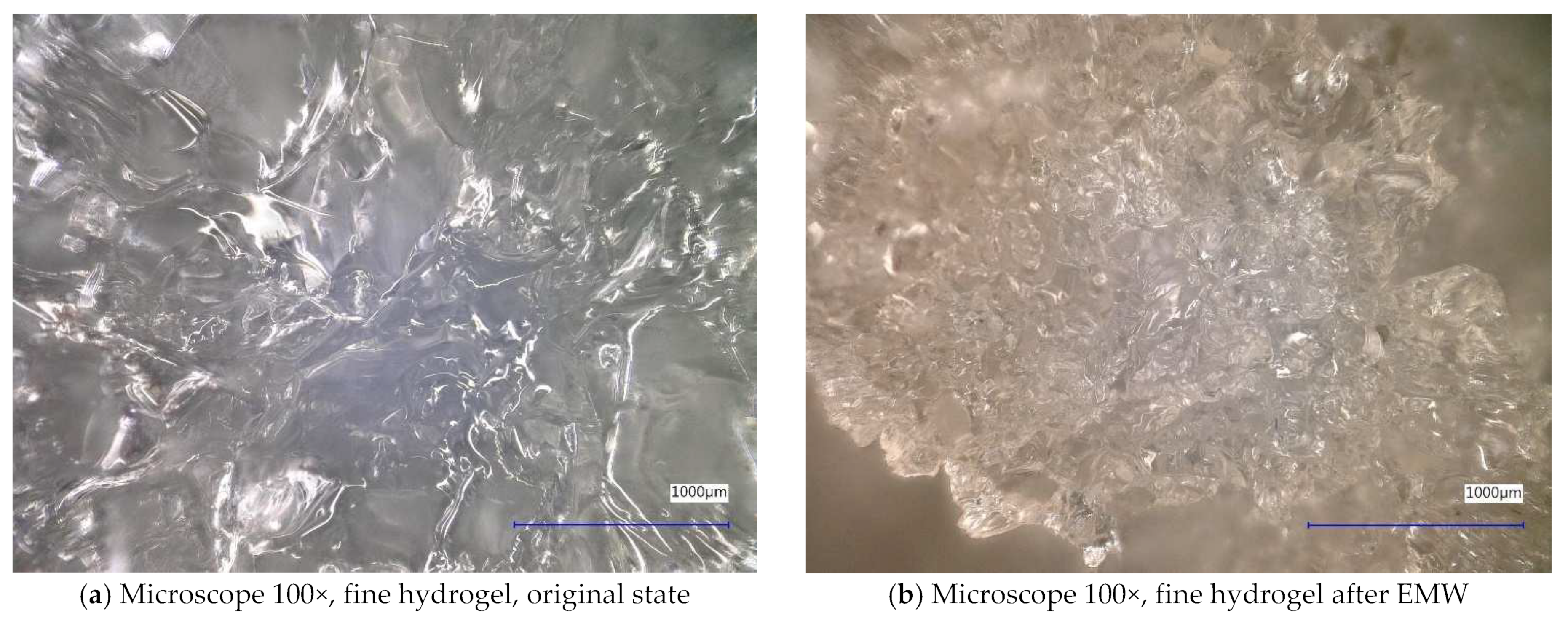
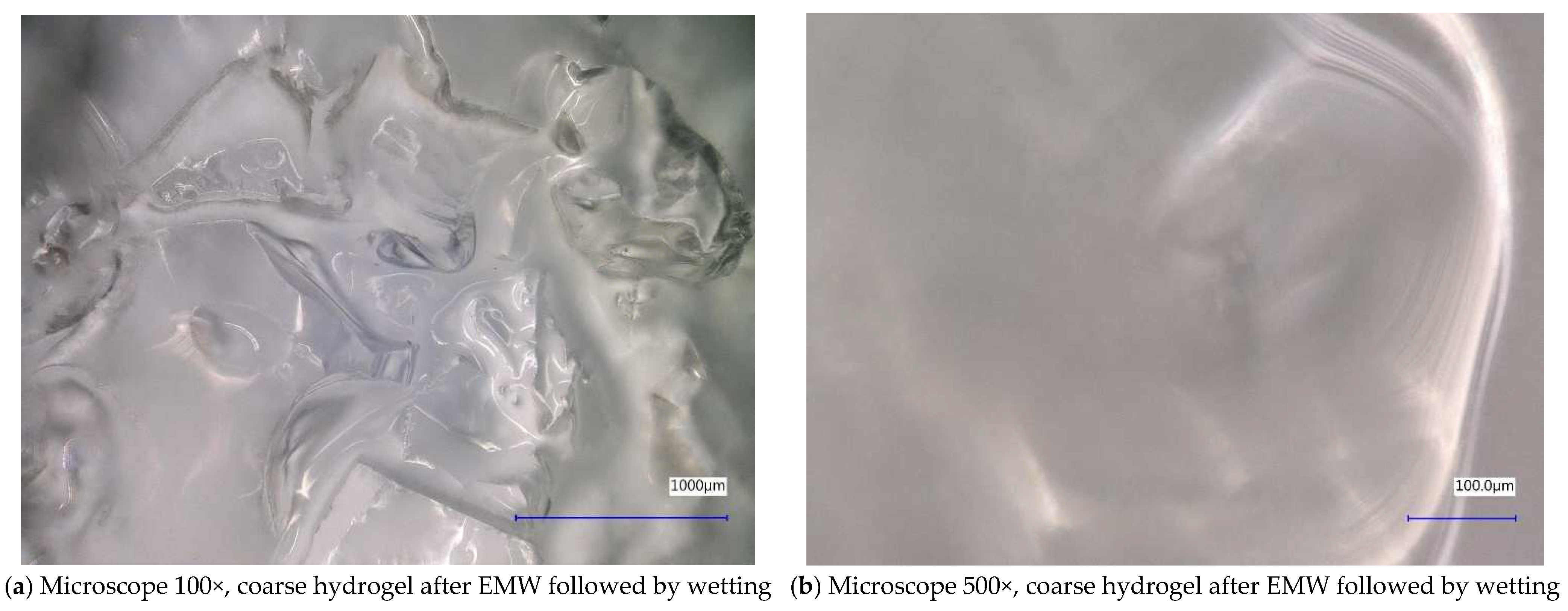
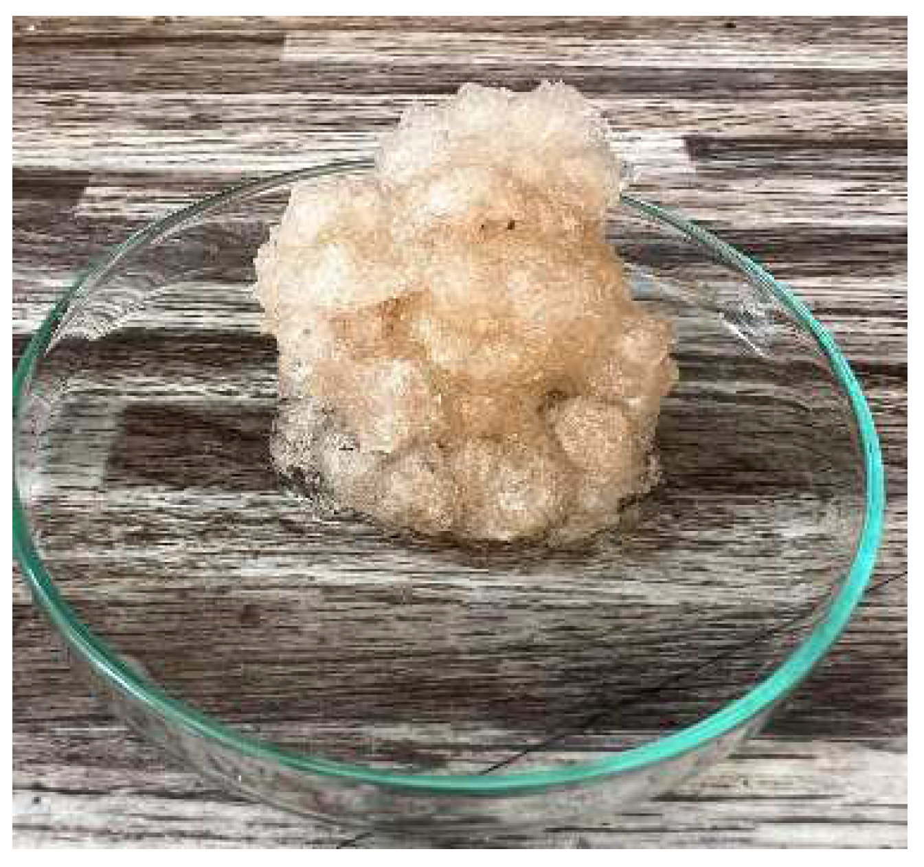
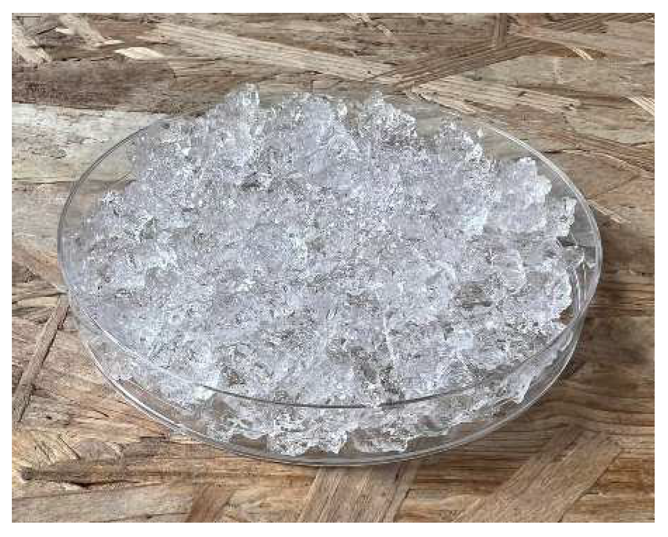
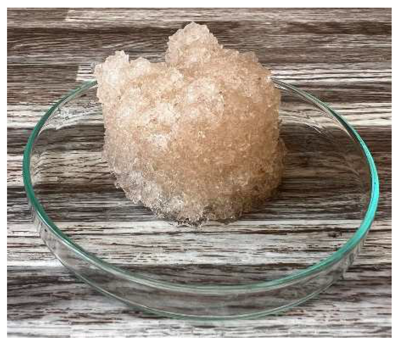
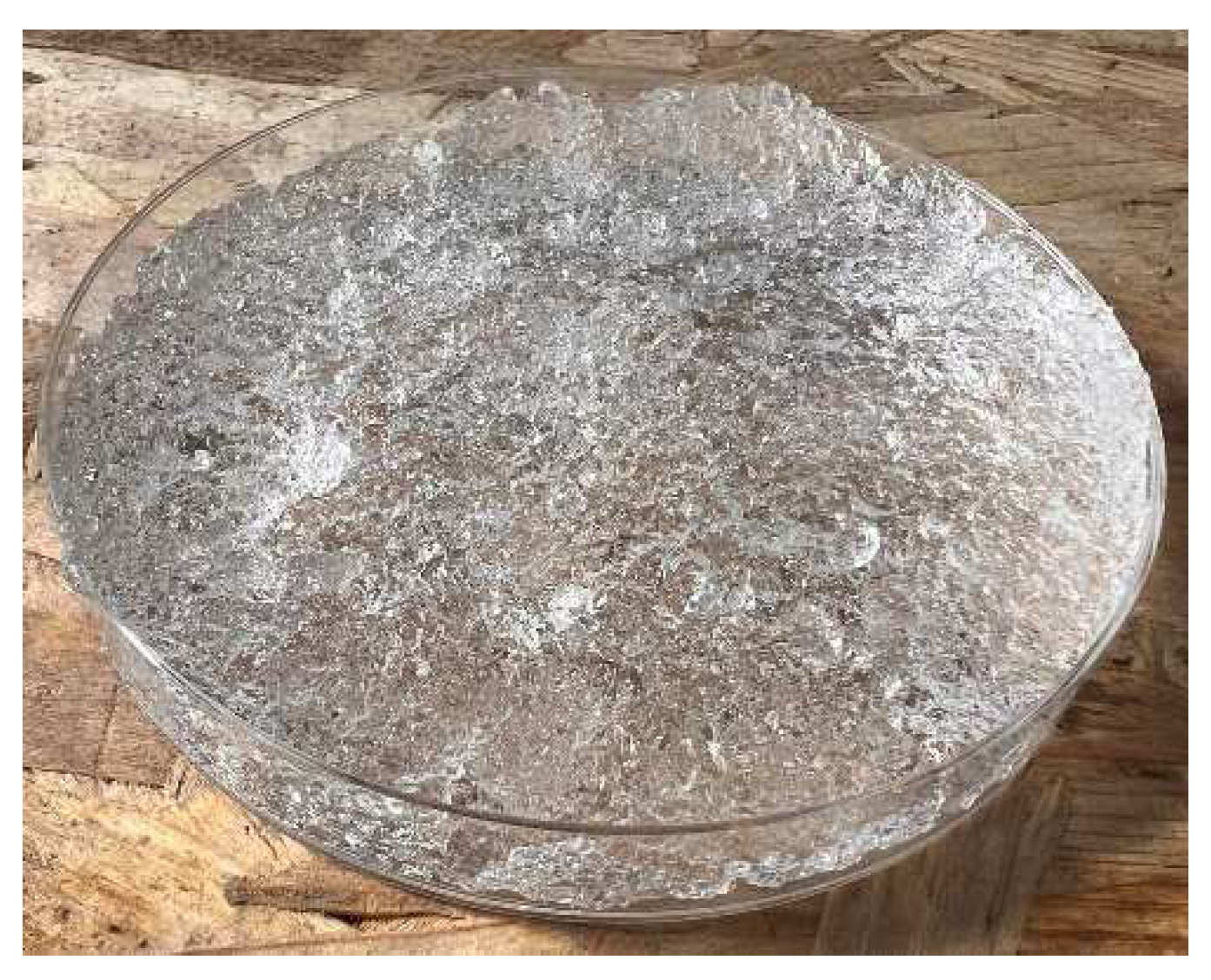
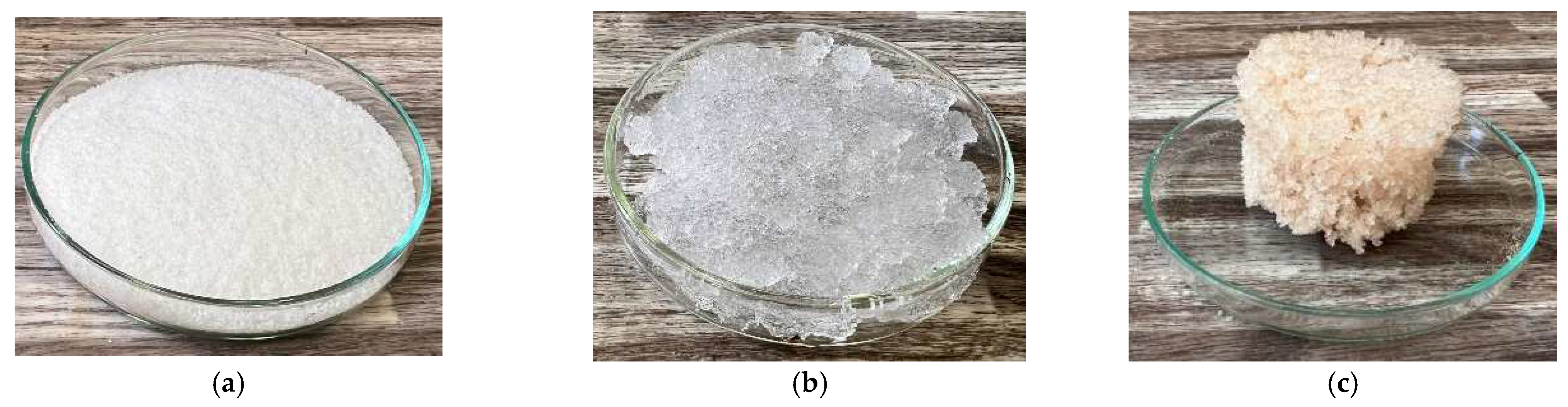
4.3. Hydrogel
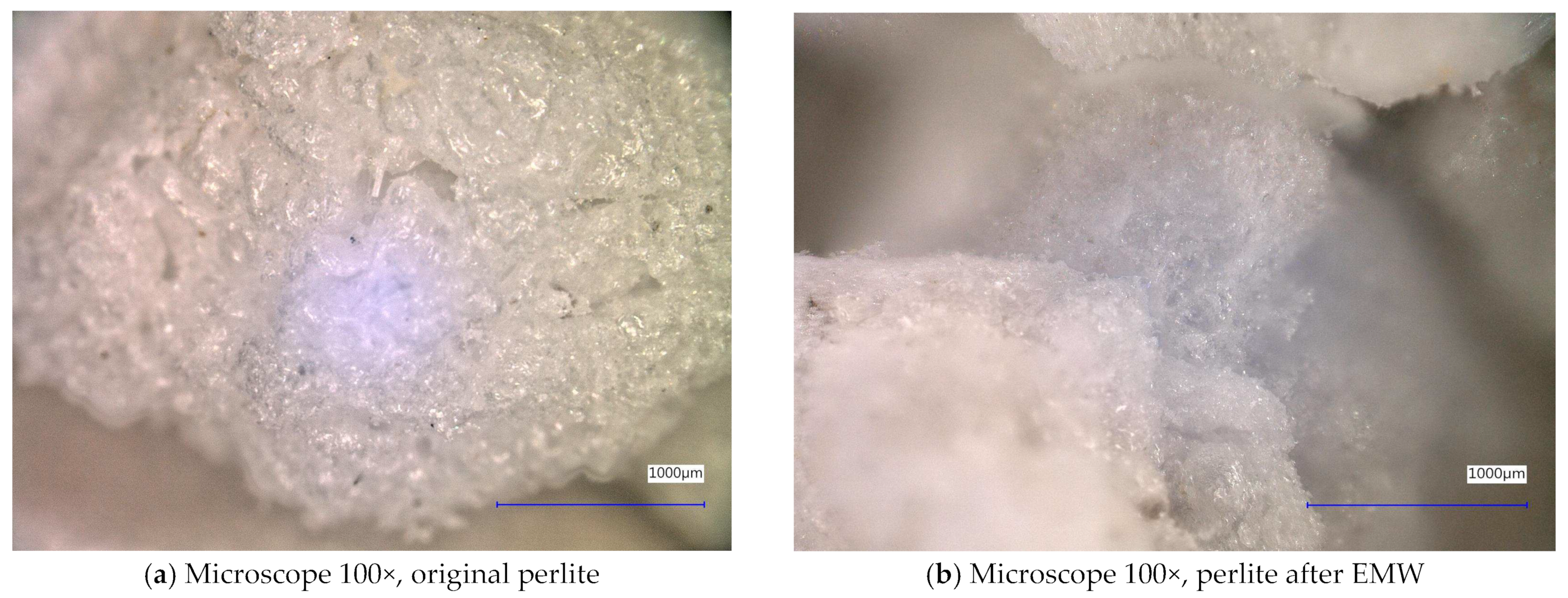
4.4. Perlite
4.5. Microwave Radiation Source
Author Contributions
Funding
Institutional Review Board Statement
Informed Consent Statement
Data Availability Statement
Conflicts of Interest
References
- Akchurin, T.; Tukhareli, V.; Pushkarskaya, O. The Modifying Additive for Concrete Compositions Based on the Oil Refinery Waste. Procedia Eng. 2016, 150, 1485–1490. [Google Scholar] [CrossRef]
- Branco, F.G.; Tadeu, A. Can cork be used as a concrete aggregate? Int. J. Hous. Sci. Its Appl. 2007, 31, 1–11. [Google Scholar]
- Vijayalakshmi, R.; Ramanagopal, S. Structural concrete using expanded clay aggregate: A review. Indian J. Sci. Technol. 2018, 11, 1–12. [Google Scholar] [CrossRef]
- Krafcik, M.J.; Macke, N.D.; Erk, K.A. Improved Concrete Materials with Hydrogel-Based Internal Curing Agents. Gels 2017, 25, 46. [Google Scholar] [CrossRef]
- Průša, D.; Šťastník, S.; Šuhajda, K.; Svobodová, K.; Žajdlík, T.; Hobzová, K.; Novotný, M. The Effect of Microwave Radiation on the Solidification of C-S-H Gels: Its Influence on the Solidified Cement Mixtures. Gels 2023, 9, 889. [Google Scholar] [CrossRef]
- Yang, K.-H.; Mun, J.-S.; Cho, M.-S. Effect of Curing Temperature Histories on the Compressive Strength Development of High-Strength Concrete. Adv. Mater. Sci. Eng. 2015, 2015, 965471. [Google Scholar]
- Yousuf, S.; Shafigh, P.; Ibrahim, Z.; Hashim, H.; Panjehpour, M. Crossover Effect in Cement-Based Materials: A Review. Appl. Sci. 2019, 9, 2776. [Google Scholar] [CrossRef]
- Al Saffar, D.M.; Al Saad, A.J.; Tayeh, B.A. Effect of internal curing on behavior of high performance concrete: An overview. Case Stud. Constr. Mater. 2019, 10, e00229. [Google Scholar] [CrossRef]
- ACI Commettee. 308R-Guide to Curing Concrete; American Concrete Institute: Farmington Hills, MI, USA, 2001. [Google Scholar]
- Bentz, D.P.; Weiss, W.J. Internal Curing: A 2010 State-of-the-Art Review; US Department of Commerce, National Institute of Standards and Technology: Gaithersburg, MD, USA, 2011; pp. 1–82. [Google Scholar]
- Bentz, D.P.; Lura, P.; Roberts, J.W. Mixture proportioning for internal curing. Concr. Int. 2005, 27, 35–40. [Google Scholar]
- Bentz, D.P. Internal curing of high-performance blended cement mortars. Mater. J. 2007, 104, 408–414. [Google Scholar]
- Bentz, D. Internal Curing: Curing Concrete from the Inside Out. Conference: ACI webinar. 2013. Available online: https://www.researchgate.net/publication/320564265_Internal_Curing_Curing_Concrete_from_the_Inside_Out/citations (accessed on 31 April 2024).
- ACI Commettee. 213-03R Guide for Structural Lightweight-Aggregate Concrete; American Concrete Institute: Farmington Hills, MI, USA, 2014. [Google Scholar]
- Panwar, S.; Jindal, A. A review on self-curing agents. Innov. Infrastruct. Solut. 2023, 8, 282. [Google Scholar]
- Vosoughi, P.; Taylor, P.; Ceylan, H. Impacts of Internal Curing on the Performance of Concrete Materials in the Laboratory and the Field; National Concrete Pavement Technology Center: Ames, IA, USA, 2017. [Google Scholar]
- Rahman, S. Investigation of Concrete Properties with Brick Chips as Internal Curing Medium. Master’s Thesis, Bangladesh University of Engineering and Technology, Dhaka, Bangladesh, 2016. [Google Scholar]
- Henkensiefken, R. Internal Curing in Cementitious Systems Made with Saturated Lightweight Aggregate. Ph.D. Dissertation, Purdue University, West Lafayette, IN, USA, 2008. [Google Scholar]
- Weiss, J.; Bentz, D.; Schindler, A.; Lura, P. Internal curing. Structure 2012, 12, 10–14. [Google Scholar]
- Kovler, K.; Jensen, O.M. Activities of RILEM technical committee: Internal curing of concrete and anticipated research. In Proceedings of the ACI Fall 2007 Convention, Fajardo, Puerto Rico, 14–18 October 2007. [Google Scholar]
- Sharma, R.; Jang, J.G.; Hu, J.W. Phase-change materials in concrete: Opportunities and challenges for sustainable construction and building materials. Materials 2022, 15, 335. [Google Scholar] [CrossRef]
- Bentz, D.P.; Stutzman, P.E. Internal curing and microstructure of high-performance mortars. In ACI SP-256, Internal Curing of High Performance Concretes: Laboratory and Field Experiences; American Concrete Institute: Farmington Hills, MI, USA, 2008; pp. 81–90. [Google Scholar]
- Bogas, J.A.; Gomes, T. Mechanical and durability behaviour of structural lightweight concrete produced with volcanic scoria. Arab. J. Sci. Eng. 2015, 40, 705–717. [Google Scholar]
- Boarder, R.F.; Owens, P.L.; Khatib, J.M. The sustainability of lightweight aggregates manufactured from clay wastes for reducing the carbon footprint of structural and foundation concrete. In Sustainability of Construction Materials, 2nd ed.; Woodhead Publishing: Cambridge, MA, USA, 2016. [Google Scholar]
- Thienel, K.C.; Haller, T.; Beuntner, N. Lightweight concrete—From basics to innovations. Materials 2020, 13, 1120. [Google Scholar] [CrossRef] [PubMed]
- Yang, L.; Shi, C.; Liu, J.; Wu, Z. Factors affecting the effectiveness of internal curing: A review. Constr. Build. Mater. 2021, 267, 121017. [Google Scholar]
- Esteves, L.P. Internal Curing in Cement-Based Materials. Ph.D. Thesis, Universidade de Aveiro, Aveiro, Portugal, 2009. [Google Scholar]
- Vázquez-Rodríguez, F.J.; Elizondo-Villareal, N.; Verástegui, L.H.; Arato Tovar, A.M.; López-Perales, J.F.; Contreras de León, J.E.; Gómez-Rodríguez, C.; Fernández-González, D.; Verdeja, L.F.; García-Quiñonez, L.V.; et al. Effect of mineral aggregates and chemical admixtures as internal curing agents on the mechanical properties and durability of high-performance concrete. Materials 2020, 13, 2090. [Google Scholar] [CrossRef]
- Kioumarsi, M.; Azarhomayun, F.; Haji, M.; Shekarchi, M. Effect of shrinkage reducing admixture on drying shrinkage of concrete with different w/c ratios. Materials 2020, 13, 5721. [Google Scholar] [CrossRef] [PubMed]
- Hamzah, N.; Mohd Saman, H.; Baghban, M.H.; Mohd Sam, A.R.; Faridmehr, I.; Muhd Sidek, M.N.; Benjeddou, O.; Huseien, G.F. A review on the use of self-curing agents and its mechanism in high-performance cementitious materials. Buildings 2022, 12, 152. [Google Scholar] [CrossRef]
- Ramzi, S.; Hajiloo, H. The effects of supplementary cementitious materials (SCMs) on the residual mechanical properties of concrete after exposure to high temperatures. Buildings 2022, 13, 103. [Google Scholar] [CrossRef]
- Park, S.; Wu, S.; Liu, Z.; Pyo, S. The role of supplementary cementitious materials (SCMs) in ultra high performance concrete (UHPC): A review. Materials 2021, 14, 1472. [Google Scholar] [CrossRef]
- Memon, S.A.; Javed, U.; Shah, M.I.; Hanif, A. Use of processed sugarcane bagasse ash in concrete as partial replacement of cement: Mechanical and durability properties. Buildings 2022, 12, 1769. [Google Scholar] [CrossRef]
- Fantilli, A.P.; Jóźwiak-Niedźwiedzka, D. Supplementary cementitious materials in concrete, part I. Materials 2021, 14, 2291. [Google Scholar] [CrossRef] [PubMed]
- Makul, N. Effect of low-pressure microwave-accelerated curing on the drying shrinkage and water permeability of Portland cement pastes. Case Stud. Constr. Mater. 2020, 13, e00358. [Google Scholar]
- Procházka, M.; Sobotka, J.; Šuhajda, K.; Novotný, M. Microwave radiation and its application on construction materials. Eng. Struct. Technol. 2016, 8, 150–156. [Google Scholar]
- Novotny, M.; Skramlik, J.; Suhajda, K.; Tichomirov, V. Sterilization of Biotic Pests by Microwave Radiation. Procedia Eng. 2013, 57, 1094–1099. [Google Scholar]
- Kvapilová, V.; Šuhajda, K. Possibility of Using Microwave Radiation for Rehabilitation of Historical Masonry Constructions. Key Eng. Mater. 2020, 868, 119–126. [Google Scholar]
- Tauhiduzzaman, M.; Hafez, I.; Bousfield, D.; Tajvidi, M. Modeling Microwave Heating and Drying of Lignocellulosic Foams through Coupled Electromagnetic and Heat Transfer Analysis. Processes 2021, 9, 2001. [Google Scholar] [CrossRef]
- Průša, D.; Šuhajda, K.; Žajdlík, T.; Svobodová, K.; Šťastník, S.; Hobzova, K.; Venkrbec, V. Effect of Microwave Radiation on the Compressive Strength of Solid Ceramic Brick. Buildings 2023, 13, 1018. [Google Scholar] [CrossRef]
- Kääriäinen, H.; Rudolph, M.; Schaurich, D.; Tulla, K.; Wiggenhauser, H. Moisture measurements in building materials with microwaves. NDT E Int. 2001, 34, 389–394. [Google Scholar]
- ČSN EN ISO 60 (642101); Plastics—Determination of Apparent Density of Material that can be Poured from a Specified Funnel. Česká Agentura pro Standardizaci: Prague, Czech Republic, 2024.
- ČSN EN ISO 16535 (727056); Thermal Insulating Products for Building Applications—Determination of Long-Term Water Absorption by Immersion. Česká Agentura pro Standardizaci: Prague, Czech Republic, 2020.
- ČSN 72 7306 (727306); Determination of Thermal Conductivity of Building Materials and Products. Česká Agentura pro Standardizaci: Prague, Czech Republic, 1995.
- Industry Statistics. Cork Quality Council. 2024. Available online: https://www.corkqc.com/pages/industry-statistics (accessed on 31 April 2024).
- Yang, C.; Gao, L.; Liu, X.; Yang, T.; Yin, G.; Chen, J.; Guo, H.; Yu, B.; Cong, H. Injectable Schiff base polysaccharide hydrogels for intraocular drug loading and release. J. Biomed. Mater. Res. A 2019, 107, 1909–1916. [Google Scholar] [PubMed]
- Wu, Z.; Hong, Y. Combination of the Silver-Ethylene Interaction and 3D Printing to Develop Antibacterial Superporous Hydrogels for Wound Management. ACS Appl. Mater. Interfaces 2019, 11, 33734–33747. [Google Scholar]
- Farghaly Aly, U.; Aboutaleb, H.A.; Abdellatif, A.A.; Sameh Tolba, N. Formulation and evaluation of simvastatin polymeric nanoparticles loaded in hydrogel for optimum wound healing purpose. Drug Des. Dev. Ther. 2019, 13, 1567–1580. [Google Scholar]
- Hu, X.; Tan, H.; Chen, P.; Wang, X.; Pang, J. Polymer Micelles Laden Hydrogel Contact Lenses for Ophthalmic Drug Delivery. J. Nanosci. Nanotechnol. 2016, 16, 5480–5488. [Google Scholar] [PubMed]
- Pimenta, A.F.R.; Ascenso, J.; Fernandes, J.C.S.; Colaço, R.; Serro, A.P.; Saramago, B. Controlled drug release from hydrogels for contact lenses: Drug partitioning and diffusion. Int. J. Pharm. 2016, 515, 467–475. [Google Scholar] [PubMed]
- De Sensale, G.R.; Goncalves, A.F. Effects of Fine LWA and SAP as Internal Water Curing Agents. Int. J. Concr. Struct. Mater. 2014, 8, 229–238. [Google Scholar]
- Grzeszczyk, S.; Janus, G. Lightweight Reactive Powder Concrete Containing Expanded Perlite. Materials 2021, 14, 3341. [Google Scholar] [CrossRef]
- Leyton-Vergara, M.; Pérez-Fargallo, A.; Pulido-Arcas, J.; Cárdenas-Triviño, G.; Piggot-Navarrete, J. Influence of Granulometry on Thermal and Mechanical Properties of Cement Mortars Containing Expanded Perlite as a Lightweight Aggregate. Materials 2019, 12, 4013. [Google Scholar] [CrossRef]
- Szafraniec, M.; Barnat-Hunek, D.; Grzegorczyk-Frańczak, M.; Trochonowicz, M. Surface Modification of Lightweight Mortars by Nanopolymers to Improve Their Water-Repellency and Durability. Materials 2020, 13, 1350. [Google Scholar] [CrossRef]
- Ariyaratne, I.E.; Ariyanayagam, A.; Mahendran, M. Bushfire-Resistant Lightweight Masonry Blocks with Expanded Perlite Aggregate. Fire 2022, 5, 132. [Google Scholar] [CrossRef]
- Beushausen, H.; Gillmer, M.; Alexander, M. The influence of superabsorbent polymers on strength and durability properties of blended cement mortars. Cem. Concr. Compos. 2014, 52, 73–80. [Google Scholar]


| Sample Identification | Bulk Density [kg·m−3] | Fraction [mm] | Absorption [%] |
|---|---|---|---|
| Sample 1: fine cork | 75 ± 5 | 0.5–1 | 800 ± 50 |
| Sample 2: coarse cork | 80 ± 5 | 1–2 | 400 ± 30 |
| Ceramsite | 500 ± 10 | 1–2 | 90 ± 10 |
| Sample 1: fine hydrogel | 100 ± 5 | 0.5–1 | 1000 ± 70 |
| Sample 2: coarse hydrogel | 100 ± 5 | 1–2 | 1000 ± 70 |
| Perlite | 60 ± 5 | 0.5–1 | 180 ± 20 |
Disclaimer/Publisher’s Note: The statements, opinions and data contained in all publications are solely those of the individual author(s) and contributor(s) and not of MDPI and/or the editor(s). MDPI and/or the editor(s) disclaim responsibility for any injury to people or property resulting from any ideas, methods, instructions or products referred to in the content. |
© 2024 by the authors. Licensee MDPI, Basel, Switzerland. This article is an open access article distributed under the terms and conditions of the Creative Commons Attribution (CC BY) license (https://creativecommons.org/licenses/by/4.0/).
Share and Cite
Průša, D.; Šťastník, S.; Svobodová, K.; Šuhajda, K.; Sochorová, Z. Effect of Microwave Radiation on the Properties of Hydrogel, Cork, Perlite, and Ceramsite. Gels 2024, 10, 543. https://doi.org/10.3390/gels10080543
Průša D, Šťastník S, Svobodová K, Šuhajda K, Sochorová Z. Effect of Microwave Radiation on the Properties of Hydrogel, Cork, Perlite, and Ceramsite. Gels. 2024; 10(8):543. https://doi.org/10.3390/gels10080543
Chicago/Turabian StylePrůša, David, Stanislav Šťastník, Kateřina Svobodová, Karel Šuhajda, and Zuzana Sochorová. 2024. "Effect of Microwave Radiation on the Properties of Hydrogel, Cork, Perlite, and Ceramsite" Gels 10, no. 8: 543. https://doi.org/10.3390/gels10080543