Abstract
Spray impacts can be found in several technical applications and consist of many single droplets, which impact under different trajectories on wetted walls. This study investigates the asymmetric crown morphology resulting from an oblique impact ( 60°) of a single droplet on a horizontal and quiescent wall film of the same liquid. A droplet generator with an accelerated needle releases the droplets ( 1.5 mm) in a controlled trajectory on a thin film ( 0.2). The impact process is recorded from two perspectives with two synchronized high-speed cameras. Varying the Weber number within the splashing regime reveals distinct crown morphologies, which are described in detail. For 500, a single central finger develops at the front of the crown, with subsequent detachments of secondary droplets. At higher (>500), a collision of the crown with the wall film shortly after impact introduces disturbances into the rim, leading to two fingers in the middle of the front crown. A further increase in (>600) intensifies the crown–film interaction, resulting in an early ejection of tiny droplets and a complete breakup of the front rim. The influence of on the crown morphology during an oblique impact is also compared to the normal impact (90°). This study paves the way for a classification of impact regimes and a comprehensive picture of the oblique impact process, which deserve more investigation.
1. Introduction
Spray impacts are part of many technical applications and environmental processes, such as the distribution of plant protection agents, coating processes, medical sprays, or soil erosion. A spray consists of many droplets which impact with different trajectories, and thus impact angles, on dry solid walls but also on walls covered with liquid films of different thicknesses. Therefore, a single droplet impact onto a wall film of the same liquid can be regarded as an elementary process in such a spray. While most research focused on the scenario of droplets impacting the wall film at a normal angle (i.e., 90°), the focus of this study is on oblique droplet impact. Its comprehensive physical description and modeling form the basis for optimizing these applications.
During a normal or oblique droplet impact on a wall film, a crown structure is formed, which is characterized by a thicker rim bounding its top (Taylor rim, [1]) due to surface tension forces. As the crown evolves, disturbances within the rim intensify and potentially result in the growth of finger-like structures. Secondary droplets can detach consecutively from the tips of these fingers. The disintegration of the primary droplet with the formation of secondary droplets is called splashing. While a crown splash is described here, it may also occur at other stages of the impact depending on the impact conditions [2,3,4]. A prompt splash is characterized by the ejection of small droplets directly after impact. A Worthington jet, with the detachment of secondary droplets, results from the break down of a crown leading to a flow back to the center of impact. In case of deposition, on the other hand, the drop merges with the wall film after impact without the ejection of secondary droplets.
Cossali et. al. [2] conducted a large experimental study on normal droplet impacts and derived an empirical correlation that describes the deposition/splashing threshold based on the fluid properties, impact conditions and film thickness. Many other studies continued with the characterization of the morphology after normal impact and the determination of regime thresholds [5,6,7]. The Weber number, , which characterizes the ratio of inertial forces to surface tension forces, is one of the significant parameters changing the impact outcome fundamentally and is often used to determine the splashing threshold by . A higher generally leads to a larger crown, a thinner crown wall as well as more and smaller secondary droplets [5,8,9]. Further studies focused on detailed investigation of the crown splashing. Roisman et al. [10] performed analytical investigations on the growth of disturbances from bending instabilities, while Agbaglah et al. [11] used numerical simulations to study the transverse instability of the rim. Their findings suggest that the rim breakup is initially driven by Rayleigh–Taylor instabilities, leading to cusps, followed by the Rayleigh–Plateau mechanism, which drives the subsequent breakup of the fingers.
However, an oblique droplet impact onto a wetted wall, which is of great relevance in real applications, changes the impact process considerably compared to a normal impact. Okawa et al. [12] experimentally investigated the ejection of secondary droplets during the impact on thick wall films, 1.7. They observed a liquid sheet similar to the shape of a ship’s prow, where a liquid column forms and secondary droplets detach. Comparing the splashing process for a normal impact to the oblique impact, they found that the number and size of secondary droplets are highly dependent on the impact angle. Other experimental studies investigated the oblique impact into deep pools [13,14]. The impacts on thin films, 0.4, are only investigated in some studies, where the wall film was inclined [15,16,17,18,19]. This either leads to limited impact angles or to a flowing wall film that induces a boundary layer in the films and disturbs the impact. In addition to this experimental work, there are also numerical studies on oblique impacts on thin films [20,21,22,23]. However, the investigation of the crown morphology and the disintegration process during an oblique droplet impact onto a quiescent and thin wall film remains to be mostly unexplored. This study starts to close this gap by describing the influence of the Weber number on the splashing process during oblique droplet impact on a thin film.
In order to investigate this, the droplet has to be shot in a trajectory. Previously, different methods were used, for example, a pressure chamber that ejects single droplets [13] or a piezoelectric actuator that produces a droplet chain from which one single droplet is isolated [14]. The latter can reach high velocities, 25 m/s, but is limited to very small droplets, 0.1 mm, which makes it impossible to investigate the impact onto a thin wall film, 0.4. Okawa et al. [12] generated a flat spray and used an orifice to obtain a single droplet. All the described methods either produce very small droplets, which prevent the investigation of thin wall films, or are limited to low velocities. For this study, a different droplet generator was used, consisting of a needle that is accelerated on a rail to produce millimeter-size droplets by a controlled detachment. The impact velocity and angle can be varied independently from each other while maintaining a constant droplet diameter.
This study is structured the following way. First, the droplet generator itself and the experimental setup with a synchronized two-perspective high-speed camera system is presented. After that, the crown morphology of a normal impact (90°) at different Weber numbers is shown for reference. This is followed by the detailed description of one exemplary oblique droplet impact. Thereafter, the influence of the Weber number on the oblique (60°) impact morphology and splashing dynamics is analyzed. At the end, the crown characteristics and their change with of the oblique impact and the normal impact are compared.
2. Experimental Method
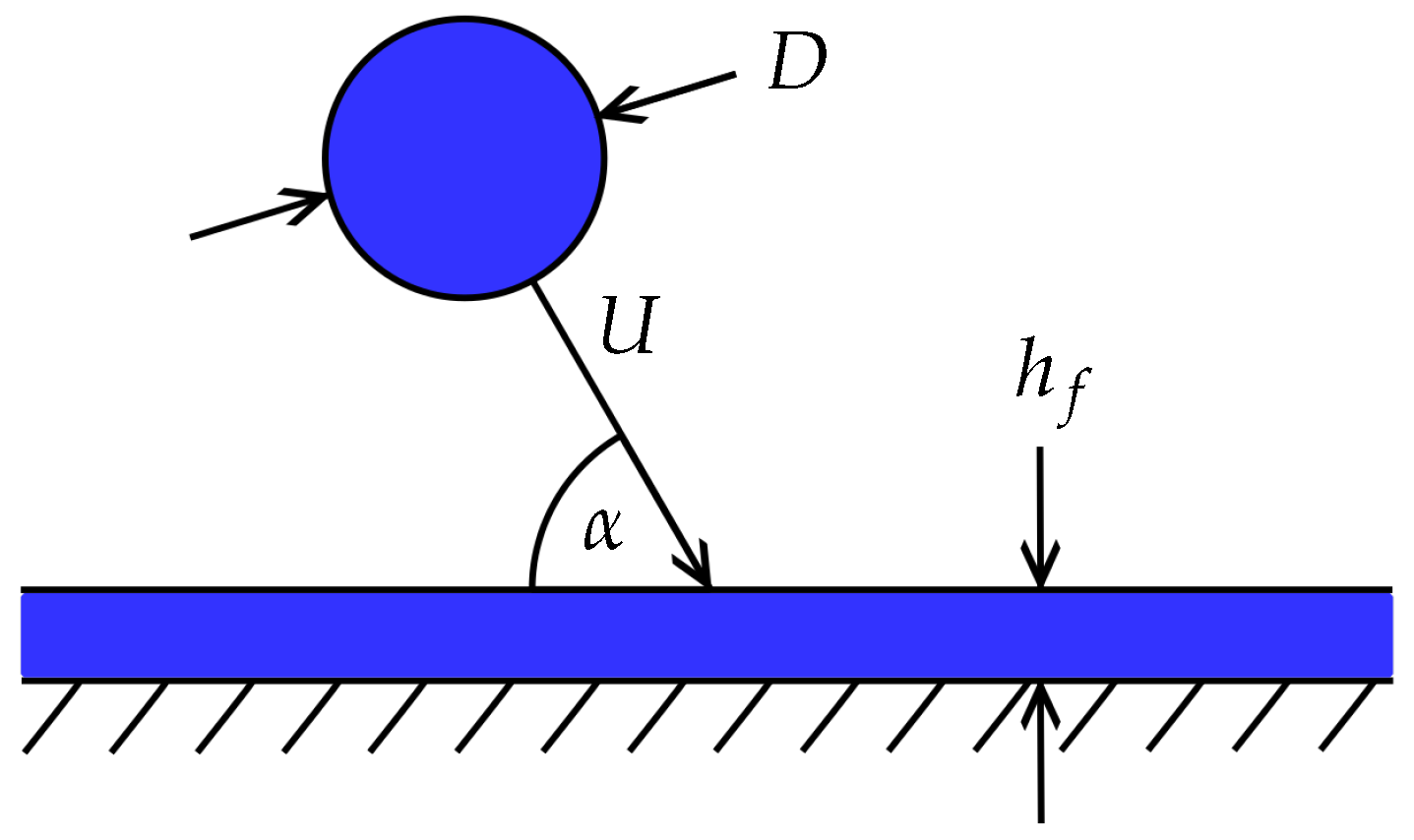
Figure 1 represents an oblique droplet impact. It is characterized by the droplet diameter D, the total impact velocity U, the impact angle and the wall film thickness . The fluid of the droplet and wall film is the same, with its properties such as the density , the surface tension and the dynamic viscosity . To summarize the impact conditions in a dimensionless manner, we consider the Weber number , the Ohnesorge number and the non-dimensional film thickness . The dimensionless time after first contact of the droplet and the wall film is defined as .

Figure 1.
Schematic representation of the impact conditions.
2.1. Oblique Droplet Generator
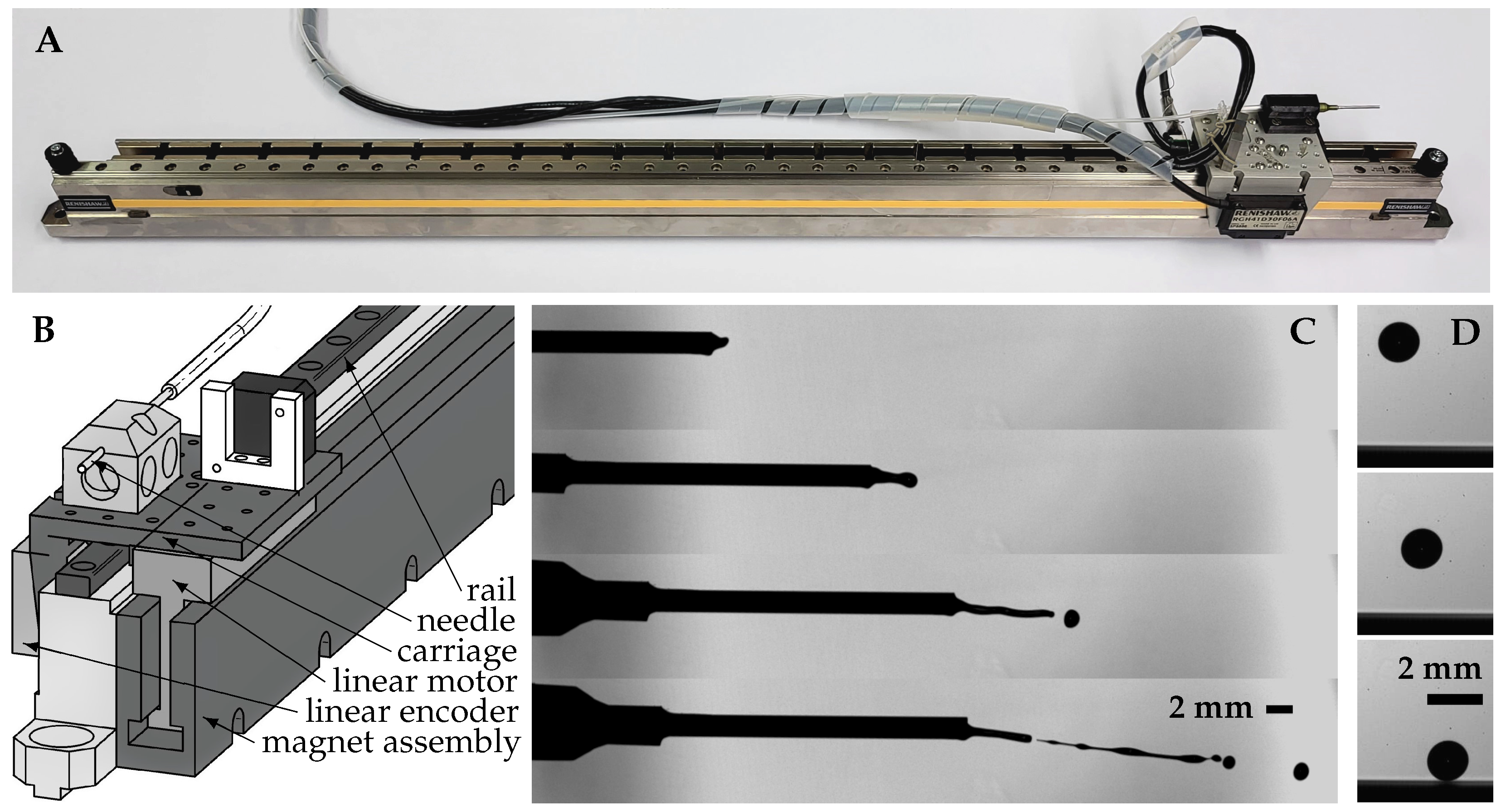
To achieve an oblique impact, the droplet has to be ejected with a horizontal velocity component. Figure 2A,B show the droplet generator, which was built for that purpose, based on the patent by Santini et al. [24]. A carriage rides along an 80 cm long rail and is powered by a brushless linear motor (H2W Technologies BLDM-B02, Santa Clarita, CA, USA). The magnet assembly for the linear motor is mounted next to the rail and covers the full length, which leads to a usable stroke of 65 cm due to the length of the carriage itself. To monitor the exact position, a linear encoder system (Renishaw RGH41, Warton, UK) is utilized. The motor and the position sensor are connected to a servo drive (Baldor MicroFlex e100, Fort Smith, AK, USA), which is controlled by an in-house Visual Basic program to define the kinematic profile of the carriage.
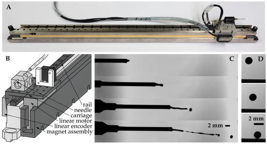
Figure 2.
(A) Photography of the oblique droplet generator, (B) sketch of the droplet generator according to the patent by Santini et al. [24], (C) high-speed camera recording of the detachment process, (D) high-speed camera recording of droplet prior to impact onto the liquid film.
A blunt syringe needle with an inner diameter of 1.5 mm is fixed on the carriage. Isopropanol is supplied to the needle through a piezoelectric pump (Bartels microtechnik mp6-liq) capable of finely tuning the mass flow rate. To achieve a reproducible and controlled detachment, the needle is driven in a periodic motion. It begins by slowly moving it backwards, followed by a constant acceleration forward to the desired velocity. Then, it decelerates to a stop at the turning point. After that, the process repeats itself. A deceleration of 130 m/s was found to be suitable to detach droplets consistently. With needle velocities in the range of 1.5 m/s 3.3 m/s, the detached droplets show a velocity in the range of 1.3 m/s 2.9 m/s.
Figure 2C illustrates the detachment process. During the high deceleration phase at the turning point, the fluid within the needle is pushed outwards due to its own inertia and forms a ligament. As more fluid exits the needle, the ligament continues to grow, consecutively detaching droplets from its end. The size and velocity of the droplets decreases as the ligament undergoes the deceleration of the needle. Consequently, only the first droplet, with the highest velocity and diameter, reaches the impact point, while the subsequent droplets follow a shorter trajectory. The diameter of the produced droplets is extremely sensitive to the mass flow rate and requires precise adjustment. Furthermore, the size of the droplets is also dependent on the needle size. In this study, a needle with an inner diameter of 1.5 mm resulted in droplets in the range of 1.2 mm 1.7 mm dependent on the mass flow rate. A thinner needle produces smaller droplets, while a larger one leads to an unstable ligament and irregular droplets. With one fixed set of tuning parameters, the droplet diameter varies in the range of 0.15 mm from one shot to the other. The produced droplets are nearly spherical and do not oscillate as can be seen from Figure 2D, which shows the droplet prior to the impact on the film. Potential oscillations resulting from the forced detachment thus have been damped before impact.
2.2. Test Stand
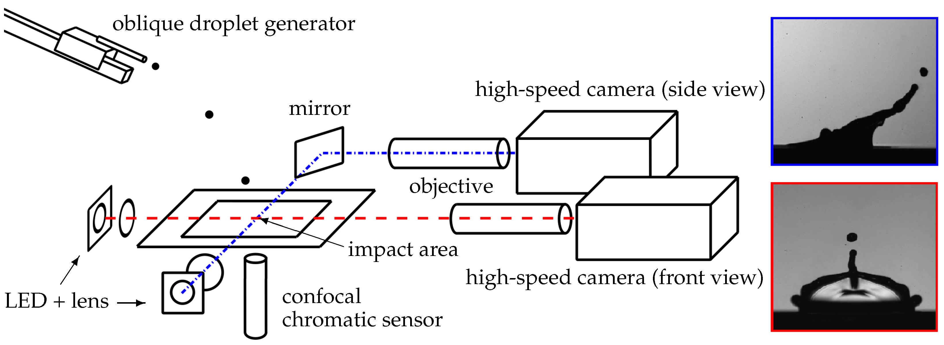
The experimental setup is illustrated in Figure 3. The imaging system comprises two synchronized high-speed cameras (Photron Fastcam SA-X2, Tokyo, Japan) capturing the process from two perspectives: a side view (blue dash-dotted line) and a front view (red dashed line). For each camera, an LED with a lens acts as a light source for the backlit shadowgraphy. The light for the side view is reflected 90° by a mirror before entering the objective mounted on the camera. Both the side view and front view utilize modular optic systems, consisting of an extension tube, a zoom module and a lower lens (side view: Optem Fusion, front view: Navitar). The cameras record with a frame rate of 12,500 fps and a resolution of 1024 × 1024 pixels. This results in a relative resolution of 24.3 /px for the side view and 21.1 /px for the front view. For the impact area, a smooth sapphire glass plate with a size of 50 mm × 50 mm and a thickness of 2 mm is used. The liquid film of isopropanol covers the complete glass plate and is held by its surface tension. The size of the glass plate ensures a flat film in the middle of the plate, where the droplet impacts. Its thickness is measured by a confocal chromatic sensor (sensor IFS2405-1, controller IFC2421MP from Micro-Epsilon, Ortenburg, Germany) continuously from below during the experiment to monitor changes due to evaporation. This also ensures that the film is static again after the previous impact and allows us to prove the flatness of the film by moving the sensor horizontally. For the confocal chromatic distance measurement, a white light source is split into different spectra. The light is focused in point but with different focal lengths dependent on the wavelength. A spectrometer measures the spectral intensity of the reflected light from the measurement object. The wavelength of the intensity peaks can be translated back into a distance with the information of the wavelength dependent focal points. For more information, see Ruprecht et al. [25]. The droplet generator is mounted on a separate frame on a different table decoupling it from the test stand to reduce disturbances of the liquid film. Its height, horizontal distance to the impact point and the inclination of the rail can be adjusted, as well as the acceleration profile and hence the detachment velocity. With that, different impact angles and velocities can be realized independently from each other, while the droplets are impacting in the middle of the sapphire plate. With the current setup, impact angles from 30° up to 80° can be achieved. The maximum impact velocity varies for each angle, mainly due to the limitations of the frame holding the droplet generator. At 80°, velocities up to 2.6 m/s can be reached, while for 50° 70°, velocities up to 3.4 m/s can be reached. For lower impact angles, 30° 40°, the achievable velocity decreases to 2.8 m/s. Due to small disturbances during the detachment process and in the surrounding air, the trajectories and thus the impact velocity and angle vary in the range of 0.2 m/s and 0.7°, respectively.
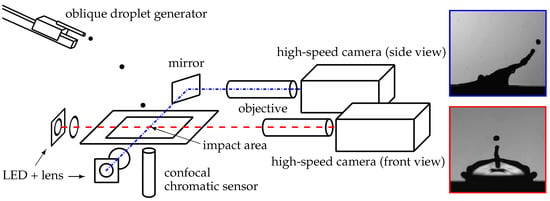
Figure 3.
Schematic representation of the experimental setup.
The experimental procedure is the following: First, the oblique droplet generator needs to be tuned in such a way that the desired impact velocity, U; impact angle, ; and droplet diameter, D, are achieved while hitting the middle of the sapphire plate. This is performed iteratively by adjusting the height, the horizontal distance and the inclination of the droplet generator as well as the detachment velocity, which is dependent on the acceleration profile and the mass flow. The impact parameters are determined retrospectively from the camera recording from the side view using an in-house Matlab (R2021a) program. The oblique droplet generator is continuously operated in a periodic motion, releasing droplets approximately every three seconds. This ensures a repeatable detachment and trajectory. At the beginning of a measurement series, the droplets are caught by a trap to apply a thin film of isopropanol on the sapphire plate. Once the film achieves its desired thickness and stability, which is monitored by the sensor, the trap is removed and a single droplet impacts. Both cameras, which are also synchronized to the film thickness measurement, record continuously until the end trigger is pulled manually. With this method, droplets impacting off-center can be sorted out by waiting for the next impact. To ensure a static film after the previous impact, every second droplet is caught with the trap. Due to the impact conditions varying from one shot to another, as described earlier, many experiments have to be conducted.
The droplet diameter is determined utilizing an in-house Matlab program, which analyses the side view of the high-speed camera recordings, assuming a spherical shape. The measurement accuracy of one pixel corresponds to an uncertainty of 1.93%, considering the resolution mentioned earlier. Similarly, the impact velocity and angle are also calculated using the Matlab program evaluating the last ten frames before impact. The velocity is measured with an uncertainty of 1.68%, and the impact angle is measured with an uncertainty of 1.35%. Since the film thickness is measured from below through the sapphire plate, the measured thickness deviates from the actual thickness. To eliminate this error, the thickness was determined with a second sensor from above at the same time to quantify the shift in the measurement. By applying that correction, the film thickness can be determined with an accuracy of 10 leading to an uncertainty of 3.3% for the film thickness investigated in this study.
3. Results
This section is structured as follows: First, in Section 3.1, the crown morphology of a normal droplet impact, i.e., 90°, for different Weber numbers is presented. In the next subsection, the outcome of one oblique impact ( 60°) experiment leading to a single central finger on one side of the crown is shown in detail. After that, the morphology change with different impact Weber numbers is presented and discussed in Section 3.3. At the end, the oblique droplet impact is compared to the normal one in Section 3.4.
In order to investigate the nature of the oblique impact, the impact angle was not set too close to 90°. However, if the angle is too small (≤45°), a comparison to normal impacts is not meaningful anymore. Therefore, an impact angle of 60° was chosen for this study.
3.1. Crown Morphology for Weber Number Variation at Normal Droplet Impact ( 90°)
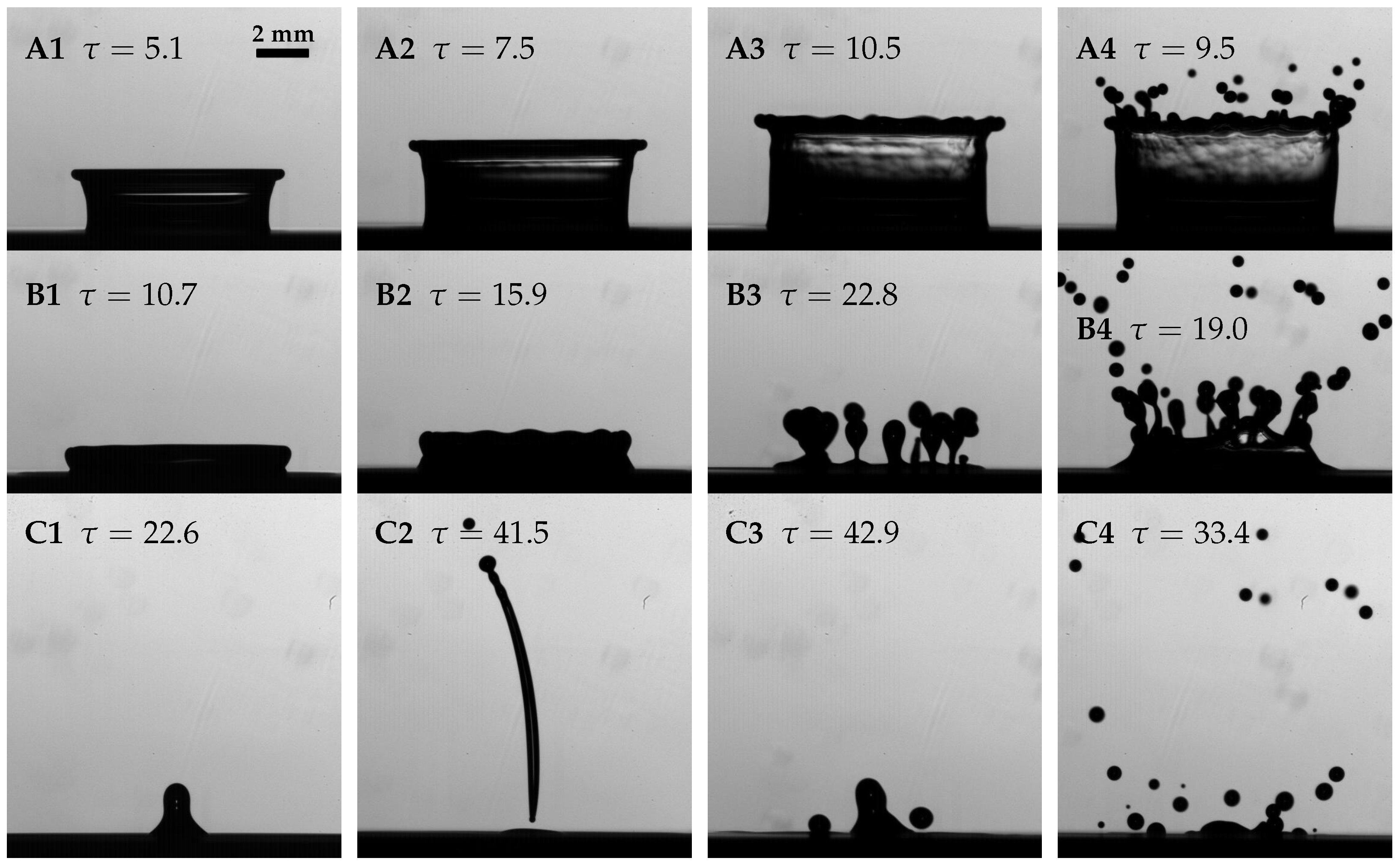
Experiments were conducted with 90° in a range of , as for the oblique droplet impact. The detailed impact conditions of the experiments shown in this and the following sections are summarized in Table 1. Figure 4 shows the crown development of Experiments 1–4 at the time of maximum crown height (A), during (B) and after the receding phase (C). With an increase of , the morphology changes the following way. For Experiment 1 ( 323), there is a smooth rim which falls down on the film again without any splashing; see Figure 4(B1). After that, a small Worthington jet [4] forms, C1. With an increase in (Experiment 2, 481), the rim remains smooth until it reaches its maximum crown height, and there is still no crown splash. During the receding, waves appear at the rim and an intense Worthington jet can be observed after that, which leads to a detachment of the jet itself and a separation into up to six droplets. Moving on to the third experiment ( 618), an increase in the Weber number results in the emergence of waves in the expansion phase of the crown, A3. During the receding phase, thick fingers start to form and comparably large droplets separate from it, which fall back onto the liquid film, B3. After that, a small Worthington jet is present without further atomization, C3. Finally, as the Weber number is further increased ( 708), fingers appear at the rim before the maximum crown height is reached, and many secondary droplets detach; see Figure 4(A4). The fingers and the secondary droplets at this Weber number are smaller in diameter and fly upwards. Additionally, consecutive detachments of more droplets from these fingers occurs during the receding phase, B4, which fall down onto the liquid film again, C4.

Table 1.
Impact conditions for all experiments shown in this study, as well as fluid properties at 22 °C.
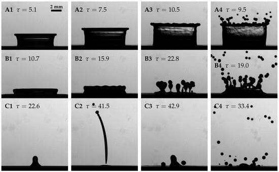
Figure 4.
Recording of the crown morphology during a normal droplet impact, i.e., 90°, for different Weber numbers. (1) Exp 1 323, (2) Exp 2 481, (3) Exp 3 618, (4) Exp 4 708. Moment of maximum crown height (A), receding phase (B), after the receding of the crown (C).
These phenomena described here were already observed by others [3,4,7,9]. The threshold derived from the correlation by Cossali et al. [2], at which splashing starts to occur, is 485. They mention a transition region in the vicinity of the threshold, in which both outcomes are possible. At the film thickness and Ohnesorge number we investigated in this study, a splashing from a Worthington jet is observed before the crown splashing. Cossali et al. also investigated this region but did not comment on splashing from a Worthington jet. However, they clearly defined splashing as the formation of secondary droplets and their threshold fits quite well with our observations.
3.2. Single Central Finger Morphology ( 60°)
The Weber number of an oblique impact can be defined either with the total impact velocity, , or with the velocity component normal to the wall film, . Using the total Weber number yields the same kinetic energy of the impact as in the normal impact. On the other hand, the normal Weber number scales with the velocity component normal to the wall, which could also be the determining quantity for the splashing characteristic. The normal Weber number is always smaller than the total Weber number; here, for 60°, approximately . In this paper, the Weber number for the oblique impact was calculated with the total impact velocity, meaning that the normal velocity component of the oblique impact is smaller than that of the normal impact at the same . Nevertheless, as shown later in Section 3.3 and Section 3.4, splashing occurs at lower in the oblique case.
In this section, the outcome of one oblique droplet impact (Experiment 6, see Table 1, 448, 59.7°) is shown and explained in detail. Figure 5 presents the development of the impact, captured by the two synchronized high-speed cameras. The left picture shows the morphology from the side view and the right picture from the front view. Both images are scaled to the same size and aligned in height. The difference visible at the film surface is due to a different depths of field and focal points for the two views. The droplet impacts obliquely from the top left; see Figure 5A showing the droplet shortly after first contact with the wall film. In Figure 5B, the early stage after impact reveals that the lamella grows flat and horizontally at the front compared to the higher rising lamella on the sides. Shortly after (see Figure 5C,D), the front lamella turns upwards and reaches higher than the lamella on the side. In picture D, at 4.3, a central finger begins to form on the front side and continues to grow diagonally upwards (Figure 5E–H). A first secondary droplet detaches from the tip of the finger at 11, see Figure 5F,G, moving upwards. At this moment, the crown has already reached its maximum height and starts to recede, first at the back and then at the side. Subsequently, the central finger also retracts while a second and a third secondary droplet separate from its tip (Figure 5I,J), which fall back down on the wall film and coalesce with it. At the rim on the side, no fingers form. Instead, one cusp develops on each side of the crown. It starts to form at 7.4, visible in Figure 5E, and becomes evident in both views in Figure 5F,G. On the back side of the crown, the crown is first bent inwards; see Figure 5C. However, a part of the crown, or at least a small finger, flips outwards later, visible in Figure 5E.
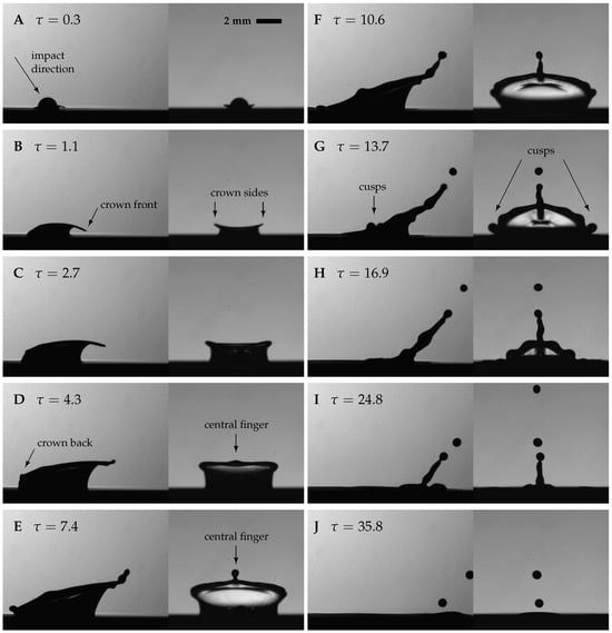
Figure 5.
Two-perspective shadowgraphy images of the crown morphology during the oblique droplet impact onto a liquid wall film, Experiment 6 ( 448, 0.0142, 59.7°); see Table 1. Left picture, side view; right picture, front view. Dimensionless time . (A) droplet shortly after impact; (B,C) stable crown development; (D,E) start of formation of central finger; (F) first detachment of secondary droplet; (G–I) crown receding; (J) 2nd and 3rd secondary droplet.
Yarin and Weiss [26] provided an explanation for the formation of fingers from the rim bounding the crown during droplet impact. According to their explanation, small disturbances in the Taylor rim [1] are amplified and lead to the formation of cusps. If the kinetic energy is sufficiently high, fingers grow from these cusps and secondary droplets separate from their tips due to the Rayleigh–Plateau instability. This mechanism is also observed in the oblique impact case shown above. However, in this particular case, one single finger grows only at the front side of the crown, which can be attributed to the horizontal velocity component of the impacting droplet. The rim at the side, however, is more stable; see Figure 5D,E. The horizontal velocity component present at the oblique impact probably induces a circumferential flow within the rim. This circumferential flow supplies the central finger and facilitates its growth.
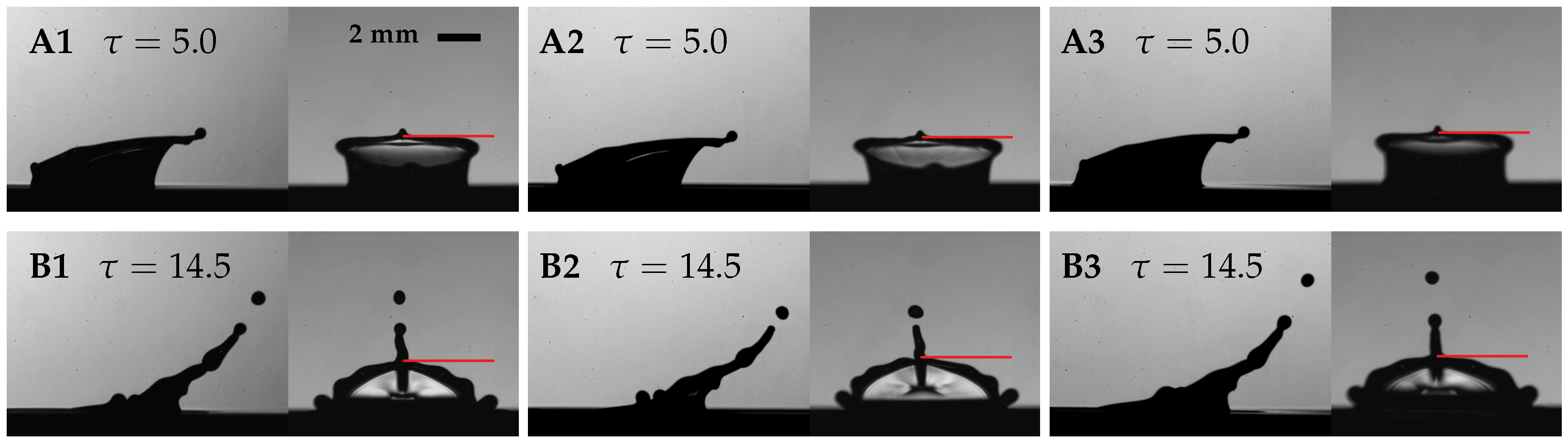
To evaluate the repeatability of the experiment, Figure 6 shows the crown morphology from three experiments with the same impact conditions at two moments in time. The first moment is during the early growth phase of the central finger, 5.0, shown in the first row. Notably, the height and the shape of the finger are the same across all experiments. Also, the overall shape of the crown is identical. At a later time, 14.5, the first secondary droplet has detached from the central finger and the crown has already started descending towards the wall film; see the second row in Figure 6. The shape of the residual crown as well as the position and size of the side cusps are similar in all three experiments. The only observable difference is the position of the secondary droplet, indicating a slight variation in the time of its separation from the finger. A comparison of later times (not shown in this figure) reveals that in all three experiments three secondary droplets detach. Additionally, the crown shape observed in the front view is remarkably symmetric. This demonstrates that the wall film is in fact flat and quiescent prior to droplet impact. Moreover, no noticeable random disturbances, such as oscillations, are introduced by the detachment of the droplet at the droplet generator.
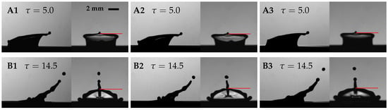
Figure 6.
Comparison of the crown morphology of three experiments. (A) 5.0, formation of central finger; (B) 14.5, crown descending phase; (1) Experiment 6 ( 448, 0.0142); (2) Experiment 6.1 ( 457, 0.0142); (3) Experiment 6.2 ( 457, 0.0141).
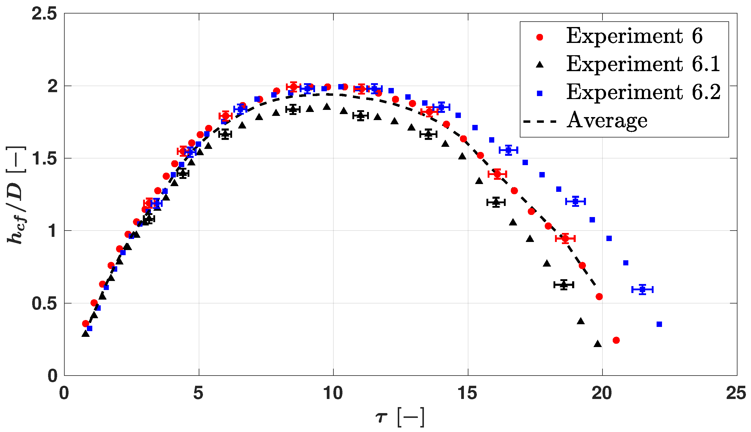
Figure 7 presents a comparison of the non-dimensional crown height on the front side as function of the non-dimensional time for the three experiments under the same conditions (Exp 6, Exp 6.1, Exp 6.2) in order to quantify the repeatability of the experiment. The crown height was measured from the front view, excluding the central finger, as indicated with the red line in Figure 6. The overall development is consistent in all experiments, and they reach their maximum crown height at 10. However, Experiment 6.1 shows a small deviation, with its maximum height being 7% lower compared to the other experiments. It is interesting to note, that the deviation starts at 5, which is the time where the central finger starts to grow. The crown height development of Experiment 6 and 6.2 aligns well within the measurement accuracy until the crown starts to recede, 14. During this phase, the rim becomes wavy, as seen in Figure 5H. Small variations in the position of the waves along the receding crown result in changes in the measured height, leading to deviations between the experiments in the receding phase.
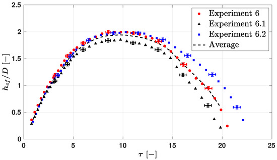
Figure 7.
Development of the non-dimensional height of the crown at the front side for three experiments with similar impact conditions. Measurement uncertainty marked by error bars for every fourth data point. Average height of three experiments plotted with the dashed line.
3.3. Variation of the Weber Number ( 60°)
Figure 8 shows the crown morphology during and oblique droplet impact of four different total Weber numbers, . It compares Experiment 6 ( 448), which was investigated in the last section, with an experiment with lower Weber number (Experiment 5 256) and two experiments with higher numbers (Experiments 7 + 8, 516, 631). The impact angle and the film thickness were kept almost constant; only the droplet diameter was increased for the last experiment to reach higher Weber numbers. The detailed impact conditions are summarized in Table 1. Experiments 6 and 7 lie in the vicinity of the deposition/splashing threshold developed by Cossali et al. [2] for normal droplet impacts on thin wall films, 485. The other experiments represent cases below (Experiment 5) and above it (Experiment 8), which does not mean that they have to lead to deposition and splashing, respectively, because the threshold was not developed for oblique impacts. The left column in Figure 8 shows a moment shortly after the start of finger formation, 6.1, and the right column a moment where the crown is in the receding phase, 13.9.
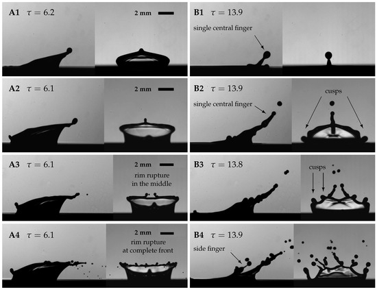
Figure 8.
Comparison of the crown morphology for four different impact We numbers. (A) 6.1, formation of fingers; (B) 13.9, crown descending phase; (1) Exp 5 256; (2) Exp 6 448, (3) Exp 7 516, (4) Exp 8 631. For all impact conditions, see Table 1.
As described in the last section, Experiment 6 is characterized by a single central finger forming at the front from which three secondary droplets detach; see Figure 8(A2,B2). At the side of the crown, two cusps can be observed. For Experiment 5, with a lower We number, shown in Figure 8(A1,B1), the crown morphology is similar with a single central finger at the front side of the crown. However, only one secondary droplet detaches in the late receding phase and falls back on the film. Furthermore, the finger is shorter and thicker in this case, and also the detached droplet is larger. If the We number is increased to 516 (Experiment 7), the crown morphology changes. Here, the rim at the front gets unstable in the middle and two main fingers are visible as well as a tiny secondary droplet which is generated very early; see Figure 8(A3). Secondary droplets detach from the fingers at the front. The fingers are thinner than the single central finger for Experiment 6 and the secondary droplets are smaller. In the receding phase, similar to Experiment 6, cusps can be found at the side of the rim. In this case, however, there are two at each side, which are larger and can be already described as small fingers. In Experiment 8, the impact velocity and the droplet diameter were increased further to reach 631. Now, the rim is unstable along the complete front, many tiny droplets are present and many fingers are formed already during the initial finger formation; see Figure 8(A4). Droplets separate from those fingers at a later point in time. Furthermore, also at the rim on the side, not only cusps, but fingers are visible and droplets detach from them.
On the one hand, the disturbances in the early rim for Experiments 7 + 8 are explained by the increase in the ratio of kinetic energy to surface tension energy, as it can be also observed for the normal droplet impact. On the other hand, here additionally a collision of the early crown with the wall film is the cause. To better observe the early phase after impact, and to confirm this statement, the experiments were reproduced with a higher magnification for the side view. Figure 9 shows the reproduced experiments which result in the outcome of a single central finger (Exp. 9) as well as an early growth of many fingers (Exp. 10 + 11); see Table 1. In the case of a single central finger, see Figure 9 first row (A1/B1), the crown does not touch the wall film at any time in the early phase after impact. However, with an increase in number, the crown interacts with the wall film in the early time; see Figure 9(A2). Note that, only the middle part of the front rim touches the film as observed from the front view perspective. This seems to introduce disturbances in this part of the rim, which lead to a partial early rupture and four fingers in the middle of the crown’s front. The third row in Figure 9(A3/B3) shows a collision of the complete front part of the crown with the wall film. This interaction is more intense and leads to the ejection of tiny droplets. The rim is unstable on the complete front of the crown, which later leads to several fingers and the detachment of many droplets.
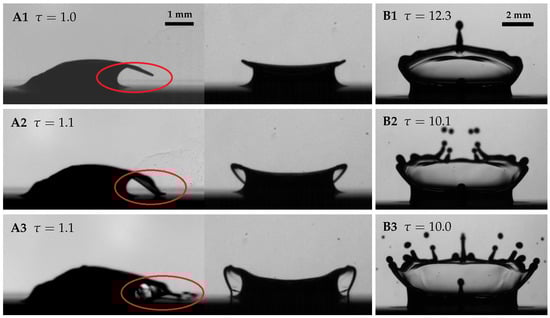
Figure 9.
Early crown morphology side and front view (A) and late crown morphology front view (B). (1) Experiment 9 508 (first row); (2) Experiment 10 610 (second row); (3) Experiment 11 675 (third row). For all impact conditions, see Table 1.
In summary, the Weber number has a big influence on the impact process and changes its outcome fundamentally. Three different morphologies can be distinguished with increasing . The first is a single central finger with the detachment of between one and four secondary droplets. Starting at low , the central finger is comparably thick and only one secondary droplet detaches during the end of the receding phase, which falls down on the film again. The rim at the side of the crown is stable without any cusps or waves on it. With an increase in , the central finger gets longer and thinner. The first secondary droplet detaches earlier, flies upwards and is smaller. Also, a second, a third and a fourth secondary droplet detach from the central finger. With increased , the rim at the side starts to show small waves and cusps. The second morphology is characterized by a partial early rim rupture in the middle with two (up to four) fingers. This is caused by a collision of the middle of the early front crown with the wall film. The fingers are thinner than the single central finger of the first morphology. Also, the trend continues so that the secondary droplets detach earlier and are smaller than at lower . The rim at the side becomes increasingly unstable showing more cusps. A third morphology was observed consisting of a complete early rim rupture with several (>4) fingers. Here, the early rupture is not only limited to the middle of the front crown, and it is caused by an intense collision of the complete front side of the early crown with the wall film.
These different outcomes are summarized in Table 2 with the range in which they were observed. The ranges overlap slightly, which is also reported in other studies that separate regimes of droplet impact, e.g., Cossali et al. [2]. The numbers separating the regime of the single central finger from the partial early rim rupture and the complete early rim rupture result to 500 and 600, respectively. Deposition, e.g., an impact without the separation of any secondary droplets, was not observed in the investigated range. Table 3 shows the splashing characteristics in from the three different morphologies by giving the numbers of fingers and secondary droplets.
Table 2.
Summary of the Weber range in which the three different morphologies were observed for 60°, 0.22 and 0.014.
Table 3.
Detailed description of observed morphologies and their splashing characteristic (number of fingers and secondary droplets).
In total, 80 experiments were conducted in a range of 249 675 for the 60° impact case with 0.22. At the points of a change in morphology ( 500 ± 20, 600 ± 20), more than ten experiments were conducted.
Table 4 gives examples of three phenomena from the literature for oblique droplet impacts, which are similar to the morphologies observed in this study. The impact conditions are listed in the table. Okawa at al. described the formation of a prow-like structure and the detachment of secondary droplets from it. This splashing mechanism is similar to the single central finger observed in this study. The Weber number was the same as in this study and the impact angle was smaller. The most significant difference is the 3.8, which can be already described as a deep pool impact. At larger and larger impact angles, Okawa et al. [12] observed an early detachment of many tiny droplets, called prompt splash. Gielen et al. [14] investigated the impact on deep pools () and determined the Weber number at which splashing starts to occur at the front side in the 60° to 370.
Table 4.
Comparable phenomena observed in the literature.
3.4. Comparison of the Oblique Impact with the Normal Impact
Comparing the oblique impact with 60° to the normal impact, the following differences in morphology become evident. The most obvious difference is that the oblique impact has only one symmetry plane and the crown is asymmetric from the side view perspective, while the normal impact is axisymmetric. Consequently, the occurrence of different phenomena, e.g., a single central finger on the front and cusps at the side, are unique features of the oblique impact. Also, a collision of the early crown with the wall film can only be observed during an oblique impact. Furthermore, the crown recedes first at the back and last at the front, whereas the crown collapses at once in the 90° case. This explains why a Worthington jet can only occur in the normal droplet impact. Another difference is that at the oblique impact splashing can be observed already at 249, while splashing from a Worthington jet and crown splash only happens at 400 and 600, respectively, in the conducted normal impact experiments. In addition to that, the trajectory of the secondary droplets follows all radial directions, while for the oblique impact, the trajectories are only directed in the direction of impact.
In addition to these differences, there are also various observations, which are similar. The progression of phenomena with increasing Weber number is the same. First, only waves and cusps form, and then fingers and the detachment of secondary droplets, which fall down on the film again. This starts to occur in the late receding phase first and shifts to earlier times if is increases further, which then leads to a ejection of secondary droplets, that fly upwards. The only difference is that this process happens for the whole crown at once for the normal impact, whereas at the oblique impact, it progresses individually for the different parts of the crown, e.g., first at the front and then for the rim at the sides. Another similarity is that the diameter of the fingers and secondary droplet decreases with an increase in .
The practical implication of the splashing characteristic of the oblique droplet impact is a significant lower splashing threshold. In other words, secondary droplets are ejected during an oblique impact at conditions where no secondary droplets are generated at a normal impact. Furthermore, the secondary droplets do not fly in all radial directions as observed in the normal impact but are ejected only in the tangential direction of the impact. These differences can be crucial for spray impact applications.
4. Conclusions and Outlook
The oblique and normal impact of a single droplet onto a thin horizontal and quiescent wall film was investigated experimentally for different Weber numbers () and the following conclusions can be drawn.
The method and the design of the oblique droplet generator, which was used in this study to shoot the droplets in a trajectory, was explained in detail, including the detachment process of the droplets from the needle tip and its tuning parameters. This setup allows us to vary the impact velocity and the impact angle independently from each other within a wide range. Furthermore, droplet impacts on deep pools as well as thin and thick wall films can be investigated in the future.
The study revealed a significant change in the morphology of the crown with increasing and thus in the disintegration of the initial droplet and the formation of secondary droplets. Three different morphologies could be identified: The first one shows a single central finger on the front of the crown with one to four secondary droplets detaching from it. The second morphology resulting from an increase in is characterized by a partial rupture of the early rim at the front, which is caused by a collision with the film. Two to four fingers are formed at the front. If the Weber number further increases, the interaction of the crown with the wall film is intensified. The rim breaks up also at the sides of the crown and several fingers form (third morphology). The critical Weber numbers separating the regime of the single central finger from the partial early rim rupture and the complete early rim rupture are 500 and 600, respectively.
A comparison to normal impacts revealed the important differences between both impact conditions. Obviously, an asymmetric crown which results in the formation of one single central finger at the front can be observed only during an oblique impact. Also, the collision of the crown with the wall film in the early time after impact only occurs during oblique impact. A Worthington jet, on the other hand, can only be found during normal impact. The progression from waves and cusps to fingers and the detachment of secondary droplets with an increase in is similar for the oblique and normal impact scenario. In addition to the different morphologies, the splashing threshold in the oblique impact case is significantly lower. Hence, secondary droplets are ejected in conditions where no secondary droplets are generated during a normal impact. Furthermore, they fly only in the tangential direction of the impact velocity, not in all radial directions as in the normal droplet impact.
This study lays the foundation for a multidimensional regime map, which is valuable for the understanding of the fundamentals of a spray process and its optimization. Future investigations varying the impact angle and the film height will enhance the described regime separation and will provide a comprehensive picture of the process.
Author Contributions
Conceptualization, all authors; methodology, all authors; validation, J.L.S.; visualization, J.L.S.; investigation, J.L.S.; writing—original draft, J.L.S.; writing—review and editing, all authors.; visualization, J.L.S.; supervision, K.S. and M.S.; project administration, K.S. and M.S.; funding acquisition, K.S. and M.S. All authors have read and agreed to the published version of the manuscript.
Funding
The authors kindly acknowledge the financial support of this work by the Deutsche Forschungsgemeinschaft (DFG) in the frame of the International Research Training Group “Droplet Interaction Technologies” (GRK2160/2: DROPIT).
Data Availability Statement
The data presented in this study are available on request from the corresponding author.
Acknowledgments
Many thanks to my student assistant Simon Weitling, who helped in conducting the experiments.
Conflicts of Interest
The authors declare no conflict of interest. The funders had no role in the design of the study; in the collection, analyses, or interpretation of data; in the writing of the manuscript; or in the decision to publish the results.
References
- Taylor, G.I. The dynamics of thin sheets of fluid. III. Disintegration of fluid sheets. Proc. R. Soc. Lond. 1959, 253, 313–321. [Google Scholar] [CrossRef]
- Cossali, G.E.; Coghe, A.; Marengo, M. The impact of a single drop on a wetted solid surface. Exp. Fluids 1997, 22, 463–472. [Google Scholar] [CrossRef]
- Deegan, R.D.; Brunet, P.; Eggers, J. Complexities of splashing. Nonlinearity 2008, 21, C1–C11. [Google Scholar] [CrossRef]
- Worthington, A. A Study of Splashed; Longmans, Green, and Co, London: London, UK, 1908. [Google Scholar]
- Vander Wal, R.L.; Berger, G.M.; Mozes, S.D. Droplets splashing upon films of the same fluid of various depths. Exp. Fluids 2005, 40, 33–52. [Google Scholar] [CrossRef]
- Rioboo, R.; Bauthier, C.; Conti, J.; Voué, M.; De Coninck, J. Experimental investigation of splash and crown formation during single drop impact on wetted surfaces. Exp. Fluids 2003, 35, 648–652. [Google Scholar] [CrossRef]
- Geppert, A.; Chatzianagnostou, D.; Meister, C.; Gomaa, H.; Lamanna, G.; Weigand, B. Classification of Impact Morphology and Splashing/Deposition Limit for n-Hexadecane. At. Sprays 2016, 26, 983–1007. [Google Scholar] [CrossRef]
- Macklin, W.C.; Metaxas, G.J. Splashing of drops on liquid layers. J. Appl. Phys. 1976, 47, 3963–3970. [Google Scholar] [CrossRef]
- Cossali, G.; Marengo, M.; Coghe, A.; Zhdanov, S. The role of time in single drop splash on thin film. Exp. Fluids 2004, 36, 888–900. [Google Scholar] [CrossRef]
- Roisman, I.V.; Horvat, K.; Tropea, C. Spray impact: Rim transverse instability initiating fingering and splash, and description of a secondary spray. Phys. Fluids 2006, 18, 102104. [Google Scholar] [CrossRef]
- Agbaglah, G.; Josserand, C.; Zaleski, S. Longitudinal instability of a liquid rim. Phys. Fluids 2013, 25, 022103. [Google Scholar] [CrossRef]
- Okawa, T.; Shiraishi, T.; Mori, T. Effect of impingement angle on the outcome of single water drop impact onto a plane water surface. Exp. Fluids 2008, 44, 331–339. [Google Scholar] [CrossRef]
- Leneweit, G.; Koehler, R.; Roesner, K.G.; Schäfer, G. Regimes of drop morphology in oblique impact on deep fluids. J. Fluid Mech. 2005, 543, 303. [Google Scholar] [CrossRef]
- Gielen, M.V.; Sleutel, P.; Benschop, J.; Riepen, M.; Voronina, V.; Visser, C.W.; Lohse, D.; Snoeijer, J.H.; Versluis, M.; Gelderblom, H. Oblique drop impact onto a deep liquid pool. Phys. Rev. Fluids 2017, 2, 83602. [Google Scholar] [CrossRef]
- Liang, G.; Guo, Y.; Yang, Y.; Zhen, N.; Shen, S. Spreading and splashing during a single drop impact on an inclined wetted surface. Acta Mech. 2013, 224, 2993–3004. [Google Scholar] [CrossRef]
- Chen, J.J.; Liu, Q.F.; Zhang, F.; Zhao, F.L.; Qu, J.Y. Experimental Investigation on Water Droplet Impacting Liquid Film on Inclined Wetted Surface. IOP Conf. Ser. Earth Environ. Sci. 2021, 701, 012005. [Google Scholar] [CrossRef]
- Che, Z.; Deygas, A.; Matar, O.K. Impact of droplets on inclined flowing liquid films. Phys. Rev. E 2015, 92, 23032. [Google Scholar] [CrossRef]
- Adebayo, I.T.; Matar, O.K. Droplet impact on flowing liquid films with inlet forcing: The splashing regime. Soft Matter 2017, 13, 7473–7485. [Google Scholar] [CrossRef]
- Kittel, H. Drop Impact onto a Wall Wetted by a Thin Film of Another Liquid. Ph.D. Thesis, Technische Universität Darmstadt, Darmstadt, Germany, 2019. [Google Scholar]
- Cheng, M.; Lou, J. A numerical study on splash of oblique drop impact on wet walls. Comput. Fluids 2015, 115, 11–24. [Google Scholar] [CrossRef]
- Brambilla, P.; Guardone, A. Assessment of dynamic adaptive grids in Volume-Of-Fluid simulations of oblique drop impacts onto liquid films. J. Comput. Appl. Math. 2015, 281, 277–283. [Google Scholar] [CrossRef]
- Guo, Y.; Lian, Y. High-speed oblique drop impact on thin liquid films. Phys. Fluids 2017, 29, 082108. [Google Scholar] [CrossRef]
- Chen, Z.; Shu, C.; Wang, Y.; Yang, L. Oblique drop impact on thin film: Splashing dynamics at moderate impingement angles. Phys. Fluids 2020, 32, 033303. [Google Scholar] [CrossRef]
- Santini, M.; Cossali, G.E.; Marengo, M. Device and Method for Drops Generation. WO 2010/021004 A1, PCT/IT2008/000554, 22 August 2008. [Google Scholar]
- Ruprecht, A.K.; Pruss, C.; Tiziani, H.J.; Osten, W.; Lucke, P.; Last, A.; Mohr, J.; Lehmann, P. Confocal micro-optical distance sensor: Principle and design. In Proceedings of the Optical Measurement Systems for Industrial Inspection IV; SPIE: Munich, Germany, 2005; Volume 5856, pp. 128–135. [Google Scholar] [CrossRef]
- Yarin, A.L.; Weiss, D.A. Impact of drops on solid surfaces: Self-similar capillary waves, and splashing as a new type of kinematic discontinuity. J. Fluid Mech. 1995, 283, 141–173. [Google Scholar] [CrossRef]


Disclaimer/Publisher’s Note: The statements, opinions and data contained in all publications are solely those of the individual author(s) and contributor(s) and not of MDPI and/or the editor(s). MDPI and/or the editor(s) disclaim responsibility for any injury to people or property resulting from any ideas, methods, instructions or products referred to in the content. |
© 2023 by the authors. Licensee MDPI, Basel, Switzerland. This article is an open access article distributed under the terms and conditions of the Creative Commons Attribution (CC BY) license (https://creativecommons.org/licenses/by/4.0/).