Abstract
As humans continue to explore the aerospace field, higher demands have been placed on new types of propulsion systems. Meanwhile, active secondary flow has been applied to various aspects of engines over the past seventy years, significantly enhancing engine performance. For the new generation of propulsion systems, active secondary flow remains a highly promising technology. This article provides an overview of the application of active secondary flow in engines, including a review of the past research on the secondary jet flow field, and an introduction of the more prominent applications of the jet in engines and its research progress. Finally, the problems existing in the current application of the secondary jet are summarized, and the future direction of the research is anticipated.
1. Introduction
As early as the last century, with the emergence of rockets and jet aircraft, the flight speed and payload capacity of aircraft and rockets were significantly improved. However, with the development of the times and the advancement of technology, in addition to enhancing the performance of aircraft, people have begun to put forward many additional requirements for aerospace propulsion systems. They hope to flexibly control the consumption of propellants through deep throttling and increase the maneuverability of aircraft by achieving thrust vectoring, and the main purpose is to enable aircraft to maintain high efficiency and adapt to different scenarios. Initially, people mainly used mechanical structures to intervene in the flow field to achieve these functions. However, mechanical adjustment methods inevitably reduced the performance of the aircraft, increased the structural weight, and faced erosion issues in high-temperature and high-speed gas environments. In addition, with the increasing complexity of mission scenarios, people also began to hope to appropriately modify the flow field characteristics of the propulsion system, such as reducing the damage caused by engine noise to personnel and instruments, reducing the infrared radiation of the wake to adapt to stealth combat scenarios, and so on. These demands are difficult to achieve through mechanical adjustments.
However, since the mid-20th century, people have begun to explore non-mechanical means to influence the gas flow field in the propulsion system, with the most common being the use of active secondary jet at a certain location in the flow field to achieve different functions. The active secondary jet is capable of changing the flow field structure by injecting one or more secondary streams into the primary flow at a specific velocity, which enables effective flow field control [1,2]. Compared with the method of changing the flow field by mechanical structure, the active secondary jet causes less total pressure loss in the primary flow and requires simpler devices [3,4]. Therefore, in practical engineering, active secondary flow has been widely applied, especially in the aerospace field, and has become one of the most promising technologies in many propulsion systems. Examples include fuel mixing in scramjet engines, thrust vector control and thrust adjustment in aeroengines and solid rocket engines, and engine noise suppression achieved through secondary jet.
Over the past 70 years, researchers have extensively studied the application of active secondary injection technology in engines. They have conducted in-depth investigations into the impact of various injection parameters, including injection angle, injection area, mass flow rate, and secondary flow temperature, on the engine’s flow field. Through numerical simulations and experiments, they have derived a set of engineering laws, which have led to improvements in existing applications and the development of new application, such as thrust enhancement and control of infrared radiation from the engine tail jet. It is evident that active secondary jet has become a focal point in the research of next-generation power systems.
Currently, scholars in the field have conducted detailed reviews on the progress of active secondary jet in a specific application. Das et al. [5] systematically summarized the research on jet thrust vector control in aerospace vehicles. Choubey et al. [6] comprehensively compiled the research progress of secondary jet application in scramjet engines. Salehian and others [7] provided a good review of active jet noise control in aerospace vehicles, highlighting the research progress in active secondary jet noise control. However, it can be seen from these reviews that most studies focus only on the characteristics of secondary jet in a single application, without considering its comprehensive performance in multiple applications. There is also a lack of comprehensive articles that organize the different applications of active secondary jet in propulsion systems. Based on the work of many scholars in the past, this paper provides a systematic summary of the application of active secondary jet in aerospace propulsion systems and proposes some suggestions for further research in this field, aiming to promote the engineering versatility and further development of this technology. This paper first summarizes the research development of active secondary jets, and then reviews the application development of active secondary jets in four aspects, namely thrust vectoring, fluid throat, fuel mixing, and jet noise control. Second, some more promising attempts of active secondary jet in engines are introduced, and finally, current problems of active secondary jet technology and prospects for future development are briefly discussed.
2. Advancements in Secondary Jet Research
The internal flow field in aerospace power systems is typically characterized by elevated temperatures and velocities. However, the addition of an active secondary jet further complicates the structures of surge systems and large-scale vortex within the engine. Early studies primarily focused on theoretical derivations and conducted numerous experimental tests to validate the impact of the active secondary jet on the high-speed mainstream. With advancements in computer technology, scholars have started employing numerical computation methods to obtain intricate details of the active secondary jet flow field and make more precise predictions.
Active secondary jets have been gradually coming to the attention of researchers since the 1940s [8]. However, in early studies, the velocity of the primary flow was very low compared to the jet. In 1953, using the traditional Helmholtz–Kirchhoff method, Ehrich F.F. et al. [9] analyzed the dynamic behavior of a jet injected into a fluid flow at an angle from gaps and orifices. They calculated relationships between geometric and velocity parameters and also determined the shape of jets in several common geometric configurations. The obtained solutions were compared with experimental data of approximate outflow from a circular orifice, which demonstrated qualitative consistency.
Later, in his study of the interaction of injected fluids with supersonic freestreams, Broadwell J.E. [10] developed a new model to predict the trajectory of jets. This model is based on the assumption that the injected jet is considered a source term for mass, momentum, and energy in the mainstream flow, and the effect of the source is largely independent of the boundary layer on the wall. This implies that the injection rate of the jet should be relatively high compared to the local mass flux of the boundary layer. When the source is concentrated at a single point, simulating the injection of gas (or rapidly evaporating liquid) from a single outlet, the pressure distribution on the wall can be analyzed using detonation wave theory. As depicted in Figure 1, the theory exhibits better agreement with the test results when both the secondary and mainstream flows are relatively low. Conversely, a significant error is observed when these flows are high.
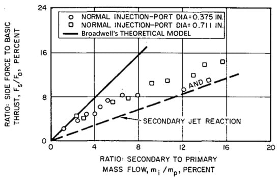
Figure 1.
Ratio of lateral and axial forces for different secondary flow ratios [10].
Next, Zukoski and colleagues [11] conducted a study on the shock wave patterns generated by secondary injection. They proposed an analysis of the jet flow field using a simplified solid body model that is capable of producing similar shock wave shapes as those observed during injection. A series of assumptions were introduced, including the consideration of the interface between the secondary jet and the mainstream as a quarter-spherical surface, followed by an axisymmetric half-body. Additionally, it was assumed that the interface between the separation flow downstream of the secondary jet and the jet itself always remains within the previously mentioned surface. Based on these assumptions, the penetration depth of the transverse jet could be derived by estimating the equivalent radius of the blunt body head. Comparisons of this parameter with experimental data demonstrated a good overall correlation under specific conditions.
Schetz et al. [12] developed an idealized and relatively simple theory based on a more representative physical model. It is assumed that the interaction between the secondary jet and the mainstream flow, as well as the subsequent diffusion, follows a two-stage process. In the penetration stage, the jet maintains its identity while being accelerated and turned in the direction of the mainstream flow. The second stage is considered a co-axial turbulent mixing process, where the drag coefficient on the “body” of the jet is assumed to be equivalent to that of an infinite cylinder at the local incident angle of the flow. By employing this approach, the trajectories of over-expanded jets and the downstream portion of the Mach disk in under-expanded jets can be computed. The experimental results demonstrate good agreement with the theoretical predictions. Building upon this, Schetz introduced the concept of “effective backpressure” to investigate the penetration effect of under-expanded jets. These findings were subsequently applied to the design of fuel injection systems in supersonic combustion ramjet engines of that era.
In 1971, Billig et al. [13] expanded upon the concept of “effective backpressure” by providing a suitable definition for it. They observed that when the structure of an under-expanded jet discharged into a crossflow resembles that of a jet discharged into a stationary medium, empirical relationships can be established to correlate the distance from the center of the Mach disk to the normal distance with the ratio of jet pressure to effective backpressure (Figure 2). Furthermore, a PL/I (IBM360) computer program was also developed for the complete numerical calculation of the trajectories to obtain the size and shape of the initial portion of the injected gas, the complete trajectory of the injected material, the trajectory downstream of the Mach disk, etc.
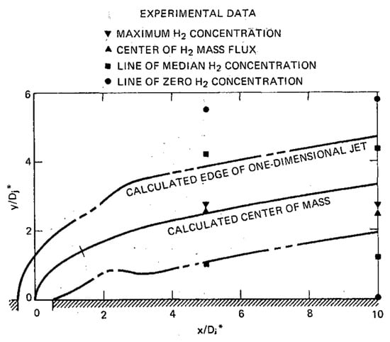
Figure 2.
Comparison of unified jet penetration model with experimental measurement. (The x-axis is defined by the ratio of the distance in the main-flow direction to the diameter of the inject hole; the y-axis is defined by the ratio of the penetration depth to the diameter of the inject hole) [13].
Up to this point, although the jet trajectories in the jet flow field have been well predicted by theoretical as well as empirical formulas, there is still a lack of analysis of the structure of the jet flow field. In 1997, Santiago et al. [14] conducted a series of experiments on secondary jets in a supersonic flow field, visualizing the flow field with schlieren/shadowgraph photography and two-component, frequency preshifted laser Doppler velocimetry, for measuring the average velocity components, the dynamical Reynolds stresses, and the turbulent kinetic energies at more than 4000 locations, with a focus on the transverse direction, the median, and the two transverse flow surfaces. The flow field details such as the structure, strength, and development of the bow shock, barrel shock, Mach disk in the secondary jet flow field, and kidney shaped counter-vortex pair, (as shown in Figure 3 for a cloud plot of the Mach number versus the Reynold number on the symmetry plane obtained from the experimental measurements by Santiago) were validated by the numerically predicted data.

Figure 3.
Cloud plot of the Mach number versus the Reynolds number on the symmetry plane obtained from the experimental measurements by Santiago. (The x-axis is defined by the ratio of the distance in the main-flow direction to the diameter of the inject hole; the y-axis is defined by the ratio of the penetration depth to the diameter of the inject hole) [14].
In the 1980s, the rapid advancement of computer technology led to the emergence of numerical methods as the primary approach for investigating complex and high-speed flow fields within engines [15,16,17,18,19,20]. In 1990, Heister et al. [21] made the initial endeavor to predict the trajectory of a jet in a secondary flow field without relying on empirical correlations. They combined analytical and numerical methods to propose a vorticity model for gas jets in supersonic crossflows. This model involved representing the cross-section of the jet with compressible vortices generated by the viscous and impulsive forces acting around the jet. The behavior of vortex pairs was then integrated with mass and momentum balance along the jet axis to formulate a model that describes the trajectory and mixing of the injected fluid. Additionally, numerical techniques were employed to solve for the inviscid external flow and positions of the expansion waves surrounding the jet. By combining this solution with the computed flow field of the compressible vortices associated with the jet, the trajectories of these gas jets could be predicted. Figure 4 illustrates a comparison between the predicted jet trajectories by Heister and the experimental data obtained by Orth et al. [22] in 1969.
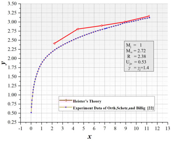
Figure 4.
Comparison of computed jet trajectories with the experimental results. (The x-axis is defined by the ratio of the distance in the main-flow direction to the diameter of the inject hole; the y-axis is defined by the ratio of the penetration depth to the diameter of the inject hole) [21].
Subsequently, as numerical computation methods continued to advance, an increasing number of turbulence models and solution techniques were developed, leading to more accurate solutions for the flow field of quadratic jets. In 1998, Wilcox [23,24,25,26] proposed the k-ω turbulence model, which has a better ability to predict separation and deal with counter-pressure gradients and separated flows compared to other two-equation models. Viti et al. [27], in a study of a supersonic secondary jet flow field with a pressure ratio of 532 and a Mach number of 4, performed a numerical simulation using the RANS method as well as a k-ω turbulence model, and the three-dimensional shock structure in the averaged flow field was described in detail. Subsequently, Peterson et al. [28] and Won et al. [29] employed the Detached Eddy Simulation (DES) method to study similar problems, and the simulated transient flow field structures and average statistical results showed good agreement with experimental observations.
Nevertheless, in the case of the intricate flow field of secondary injection in supersonic flows, achieving both high accuracy and a sufficiently dense grid density to capture smaller vortex structures is challenging. Neither the Reynolds-Averaged Navier–Stokes (RANS) nor Detached Eddy Simulation (DES) methods can fully meet these requirements. As a result, the Large Eddy Simulation (LES) method has emerged as a viable approach for investigating secondary injection. In 2010, Kawai et al. [30] utilized LES to study the injection of under-expanded supersonic jets into supersonic crossflows, aiming to replicate the experiments conducted by Santiago et al. [14] mentioned earlier. They successfully simulated the observed shock wave systems and vortex structures in the experiments. The time-averaged flow field was compared with experimental results, and a good agreement was observed.
Subsequently, researchers have made significant progress in obtaining accurate flow field structures and parameter distributions through the use of sophisticated numerical methods and models. These advancements in numerical simulations have also led to the development of various forms of secondary injection that cater to specific engineering requirements, such as pulsed jet [31,32,33], gas-solid two-phase injection [34,35,36], and liquid secondary injection [37,38,39,40]. Numerous scholars have conducted research and analysis on liquid secondary injection. This paper will not delve further into that topic.
3. Thrust Adjustment by Fluid Throat
Unlike aeroengines, where thrust adjustment is easier to achieve, rocket motors, especially solid rocket motors, have a solid propellant that determines the change in thrust during the operation of the motor, thus limiting the flexibility of solid rocket motors. In addition, while liquid rocket motors possess the capability to adjust thrust, they are not always able to operate along the most efficient thrust curve, which requires additional technological assistance. Previous studies have demonstrated that adjusting the throat area can effectively regulate the thrust of solid rocket motors and provide liquid rocket motors with higher performance and chamber pressure [41,42]. Two prominent technologies in this regard are pintle throat [43,44,45] and fluidic throat technology.
As is shown in Figure 5, in fluid throat technology, the primary flow is compressed by the secondary flow, thereby reducing the throat area of the primary flow and creating a flow region smaller than the geometric throat of the nozzle. As the primary flow gas expands along the aerodynamic wall region, the sonic velocity surface of the nozzle moves towards the smallest cross-section of the flow region. This results in changes in the thrust, main flow rate, and combustion chamber pressure of the solid rocket motor.
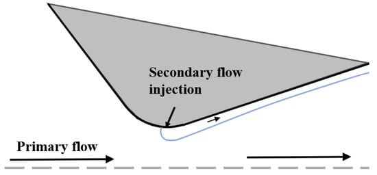
Figure 5.
Schematic diagram of fluid throat structure.
As early as 1957, Martin A.I. [46] conducted research on the thrust adjustment effect of helium jet injection in one-dimensional isentropic flow of nozzles. Disregarding heat transfer, Martin A.I.’s study established a one-dimensional isentropic compressible model about the mixing and vortex layer separation modes. The study aimed to investigate the influence of various parameters, including injection pressures, drop pressure ratios, injection angles, and mass flow rate ratios, on the throttling effect of fluidic throats and its impact on thrust, which indicated some characteristics of fluidic throat technology such as the throttling effect increased with higher mass flow ratios and so on. However, due to many simplifications in the theoretical model, significant disparities emerged between Martin A.I.’s theoretical predictions and experimental results regarding the performance of the fluidic throat nozzle. Nonetheless, subsequent researchers swiftly refined Martin’s model and initiated a series of studies applying fluidic throat technology to rocket engines.
In 1961, based on the research by Martin, Gunter [47] further refined his theoretical model and used it to carry out a study on throttling by injecting gas into the nozzle, and found that the best throttling effect can be achieved when the secondary gas is injected into the throat, where the fluid behaves as if throttling is carried out by changing the throat area. Furthermore, Gunter investigated the influence of jet temperature and jet gas type on throttling efficiency. The study revealed that the throttling effect exhibited a proportional variation to the square root of the total temperature ratio. Additionally, it was observed that a smaller specific heat ratio and molar mass of the jet resulted in a more favorable throttling effect. Among the different gases considered, helium was deemed the most promising for throttling purposes due to its low molar mass.
In the field of solid rocket engines, Zumwalt and Jackomis [48] conducted research on controlling the thrust of solid rocket engines using fluidic throat methods. They observed that the injection effectiveness significantly decreased when the nozzle was aimed downstream of the supersonic diffuser section. This observation was confirmed in preliminary Computational Fluid Dynamics (CFD) studies, and subsequent research by Lockheed Martin Tactical Aircraft Systems (LMTAS) was limited to injection angles ranging from normal to upstream tilt.
As research progressed, it became increasingly evident that for liquid rocket engines, deep throttling could theoretically be achieved by modifying the throat area of nozzle. However, practical development and implementation of this method are limited by existing engineering constraints. This is because, under constant propellant injection pressure, the throat area is constrained by the jet injection, which raises the combustion chamber pressure and diminishes the drop in propellant injection pressure and flow rate. Consequently, the decrease in propellant flow rate results in a reduction in combustion chamber pressure. Ultimately, this results in a large number of jets being injected, but only a small change in thrust [49,50]. Afterward, the research focus shifted towards aerospace engines and related studies on throat pulse jet injection.
In the 1990s, for the turbofan engines at that time, in order to maintain the flow rate and back pressure under the engine’s afterburning state, the nozzle was generally in the form of a mechanically variable nozzle. Fluid throat technology enables even simple fixed nozzles to achieve the above effect by changing the effective throat area [51]. In 1995, the US Air Force (USAF) and the National Aeronautics and Space Administration (NASA) jointly conducted a research program called “The Fluidic Injection Nozzle Technology (FLINT)”, with the expectation that the addition of secondary jets to the nozzle would replace the bulkier and heavier mechanical adjustment mechanism and improve engine performance [52,53]. One of the main directions of this program is the application of fluid throats in aeroengines.
D.N. Miller et al. [51] conducted ground-based scaled-down cold flow tests on fluidic throat technology in small expansion ratio nozzles. They also performed three-dimensional numerical simulations with an external flow field, utilizing CFD simulations to investigate four parameters: secondary flow injection angle, secondary flow jet position, throat curvature, and nozzle convergence angle. The following conclusions were reached:
- (1)
- The efficiency improvement of dual nozzles is not significant;
- (2)
- The larger the reverse injection angle, the greater the range of variation in the effective throat area;
- (3)
- The closer the nozzle is to the throat, the higher the fluid throat performance is;
- (4)
- A small curvature of the throat results in high FNT performance. However, beyond a certain value, increasing the curvature does not yield significant improvements;
- (5)
- A small nozzle convergence angle can improve the FNT performance, but there will be a peak value;
- (6)
- Increasing the mass flow ratio or total temperature ratio significantly improves FNT choke performance;
- (7)
- The small expansion ratio nozzle may have greater choke performance.
In the same year, with the support of Lockheed Martin and Pratt and Whitney, Catt [54] designed experiments to further obtain and validate the conclusions of D.N. Miller’s calculations, which concluded that the use of jet injection can simplify the structure of the turbojet engine system, reduce the cost, and improve the performance and reliability. However, achieving further advancements in the efficiency of jet injection and increasing the regulation ratio of the throat area necessitates more extensive and in-depth research efforts.
Around the same time, research on pulse jet injection also caught the attention of researchers. In 1994, Randolph et al. [55] conducted a study on pulse jet injection under supersonic flow conditions using a wind tunnel. They maintained the peak pressure of the pulse jet consistent with the steady-state jet pressure. It was found that, compared to steady jet injection, pulse jet injection could increase penetration depth without increasing the momentum flux ratio (as shown in Figure 6).
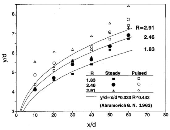
Figure 6.
Comparison of pulsed and steady injection penetration, (Steady injection data refer from [56]). The x-axis is defined by the ratio of the distance in the main-flow direction to the diameter of the inject hole; the y-axis is defined by the ratio of the penetration depth to the diameter of the inject hole [55].
Immediately after that, in 1997, S. Walker and others [52] conducted a study related to pulsed jets in fluid throats, and the test found that compared with steady jet, pulsed jet has the following characteristics: the pressure pulsation of the secondary flow nozzle causes the generation of vortex strings in the injected jet, and the vortex strings enhance the interaction of the jet with the primary flow, which intensify the throttling ability of the secondary flow. Since then, researchers have attempted to apply this approach to reduce the mass flow of secondary jet required to be injected.
Based on the development of pulsating injection, in 2007, the US Air Force re-initiated the study of fluid throats for liquid rocket motors, and D. Baruzzini [57] reported the numerical simulation to calculate the effect of steady injection versus pulsed injection on the performance of a rocket motor nozzle. The steady simulations employed the RANS turbulence model, while the pulsed simulations utilized the LES turbulence model. The effects of various parameters, such as injection angle, injection position relative to the geometrical throat, and pulsed Strouhal number, were analyzed. The findings indicated that a more effective throttling effect could be achieved when the injector was positioned slightly forward of the geometrical throat. With 30° injection in the upstream direction, the engine performs slightly better than 45° injection. At the same time, lower pulse frequency may cause significant fluctuations in the internal flow field of the engine. However, excessively high pulse frequency does not result in significant differences in penetration effects compared to steady injection. In the same year, N.D. Domel [58] conducted related research and quantitatively analyzed the time-averaged fluxes of mass, momentum, and energy in pulse jet injection. It was found that the thrust benefits from using pulse jet injection and jet control could not offset the increase in mass caused by the addition of the injection device. However, it was also noted that for spacecraft operating for extended periods in low orbits, the variations of back pressure are more significant, making the thrust benefits of jet injection more pronounced.
However, up until now, research on pulsating jet injection in fluidic throat is still in the exploratory stage compared to steady-state injection. There is still debate regarding the practical contributions and benefits of these injection devices. The best throttling performance obtained in experiments, numerical simulations, and theoretical studies has not shown a significant increase compared to steady injection, as researchers had initially anticipated.
However, during the same period, in order to obtain more reliable design methods for fluidic throats in solid rocket engines, Xie Kan et al. [59,60,61] made significant achievements in the field of fluidic throat in solid rocket engines. Researchers conducted extensive numerical simulations to examine the impact of different parameters related to secondary flow (such as angle, flow ratio, position, and nozzle hole distribution) on the internal flow field parameters and dynamic characteristics of the motor. Furthermore, they conducted experimental studies on fluidic throat nozzles using nitrogen as the jet gas to validate the fluidic throat phenomena observed in the simulations. The experimental devices used for these studies are depicted in Figure 7.
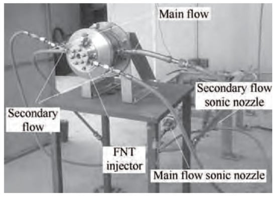
Figure 7.
Solid rocket motor cold flow test system diagram [61].
Subsequently, Yue [62] added copper powder and strontium perchlorate solution into the secondary flow, and the corresponding numerical simulations and experimental studies showed that the addition of catalytic copper powder significantly improved the thrust response speed, while the oxidizing strontium perchlorate solution was able to increase the choking performance of the fluid throat to a certain extent.
Notably, in 2017, based on Xie Kan et al., Guo [4,63] investigated the thrust adjustment characteristics and thrust vector control characteristics of the fluid throat in a solid rocket motor through experiments and numerical simulations. The effects of jet flow ratio, secondary jet nozzle diameter, jet angle, and chemical reaction on the thrust adjustment range and adjustment response characteristics of the solid rocket motor were investigated, and the theoretical model of the fluid throat in the case of vertical injection was proposed:
where is the effective throat area ratio, is the equivalent mass flow ratio of the secondary flow to the primary flow, and is a constant related to the primary flow gas. As shown in Figure 8, the proposed theoretical model demonstrates good agreement with both CFD simulation results and previous experimental findings. However, the study also indicates that achieving a relatively sizable throat area ratio solely through fluidic throats necessitates a significant amount of secondary flow injection. This may not be an economically viable solution for solid rocket motors. Consequently, research on controlling the effective throat area using fluidic throats has gradually diminished since then.

Figure 8.
Comparison of theoretical, numerical simulation, and experimental results [61,63].
However, in 2020, Yan et al. [64] proposed a novel thrust adjustment method called the Fluidic Pintle Nozzle (FPN), which combines a secondary jet and a pintle structure. This method focuses on adjusting the throat area by moving the pintle backward and forward along the axial direction. Additionally, coolant is injected into the pintle surface through openings to prevent the detrimental effects of high temperature gas on the pintle. The specific structure and principle of the FPN are illustrated in Figure 9. Numerical simulations conducted by Yan et al. demonstrate that the effectiveness of fluidic adjustment increases as the geometric area of the throat decreases when the pintle is moved. Moreover, when the pintle is utilized to regulate the geometric area of the throat, the adjustment performance is enhanced with an increase in the secondary flow rate; however, the regulation effect weakens when the corrected flow rate ratio exceeds 0.3.
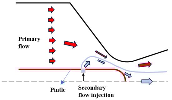
Figure 9.
Scheme of secondary injection in pintle motor.
In 2023, Z. Yang et al. [65] conducted further research on the influence of secondary flow on nozzle erosion in the FPN based on Yan’s work. They established a surface chemical reaction model under fluid–solid coupling and investigated the fundamental laws and factors about the nozzle erosion rate by various openings, injection positions, and secondary flow temperatures through numerical calculations. The results revealed notable differences in the erosion rate of nozzles with different openings. The injection of a low-temperature jet was found to effectively reduce the temperature of the pintle resulting in a decrease in the erosion rate of the pintle, which demonstrated a significant protective effect on the pintle downstream of the injection.
4. Thrust Vectoring
Thrust vectoring based on secondary jet injection was studied earlier than the fluidic throat technology and has more practical engineering applications; meanwhile, various vectoring control forms have been developed, such as the fluidic throat skewing (FTS), the shock vector control (SVC), the counter flow thrust vectoring scheme, etc. Among them, the FTS and the SVC are considered to be the most promising and widely used in all kinds of aeroengines and rocket motors.
As shown in Figure 10a, the SVC scheme entails injecting a jet asymmetrically into the supersonic primary flow of the nozzle expansion section. This generates a powerful oblique shock, causing the primary flow passing through it to experience supersonic deflection and resulting in thrust vectoring. This scheme has several advantages, including rapid frequency response and high efficiency.
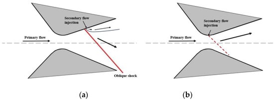
Figure 10.
Schematic diagram of SVC (a) and FTS (b).
As shown in Figure 10b, FTS refers to the asymmetric injection of the jet in the nozzle throat, which makes the primary flow’s sonic plane deflect, and then changes the flow direction of the primary flow to generate thrust vector. Compared with the SVC scheme, the FTS scheme has a smaller loss of thrust efficiency, but its vectoring efficiency is not as high. The improved double-throat FTS scheme, which realizes a much larger vectoring angle than that of the single-throat tilt scheme, has been widely used in the research of aeroengines.
In 1964, Zukoski [11] and colleagues conducted a series of wind tunnel tests to investigate the flow field around an injection port for secondary injection into a supersonic stream. The tests provided insights into the pressure field, concentration field, and shape of the shock. Nitrogen, argon, and helium were chosen as jetting gas, with free stream Mach numbers ranging from 1.38 to 4.54. The research culminated in the development of a scaling parameter that enables simple prediction of the lateral forces generated by secondary injection.
In 1965, Hsia [66] studied the shock phenomenon generated by injecting liquids in a supersonic nozzle, using nitrogen as the primary flow with gaseous nitrogen, liquid nitrogen, and Freon-12 as the injection media. Meanwhile, they took photographs under different injection conditions using the Schlieren method, which showed that the shape of the shock in the nozzle could be well predicted by the second-order explosion theory.
By the 1980s, the NASA LRC was conducting eight research programs on SVC, and in 1981, NASA’s C. L. Martin [67] attempted to apply liquid injection thrust vector control (LITVC) to the solid rocket booster (SRB) system. It was analyzed and found that LITVC performed well at low and medium load cycles (less than 100 degrees/s, 3.5 degrees maximum) but poorly at high loads (270 degrees/s, 6 degrees maximum). Considering constraints such as structural hardware, C.L. Martin concluded that it is not cost effective to implement SRB vector control via LITVC.
In 1985, as part of the fluid yaw vectoring nozzle (FYVN) program, Deere, K.A. [68] and his colleagues at NASA LRC conducted a pioneering study on throat offset technology for achieving thrust vectoring in both single- and twin-engine nozzle configurations. This study also marked the first testing of a model featuring a throat offset vectoring nozzle.
Since the 1990s, the rapid development of CFD technology has made great progress in the numerical study of thrust vectoring technology. R. Balu [69] first carried out three-dimensional flow field simulation for high-temperature gas injection and analyzed the effects of different injection parameters, and his simulation results were in good agreement with the experimental results, which verified the feasibility of the numerical model. After that, D. Azevedo [70] carried out a further study by numerical simulation, and found that the performance of the jet thrust vector depends on the injection angle of the jet air, and based on the simulation and experimental results, he inductively proposed a one-dimensional thrust coefficient prediction formula, which has a good accuracy when the flow ratio is less than 6%.
In 2001, P.J. Yagle et al. [71] of Lockheed Martin analyzed the effect of FTS scheme on the thrust vectoring performance and efficiency of aeroengine using a non-axisymmetric nozzle. The results show that the FTS scheme is a feasible thrust vectoring adjustment scheme, which has less impact on engine thrust efficiency compared to other thrust vectoring schemes. Under design conditions, FTS scheme is able to obtain 2° yaw angle and 1.7° pitch angle per 1% jet flow. At lower NPR, it gives better thrust vectoring performance.
In order to enhance the thrust vectoring performance of the FTS nozzle, Deere, K. A., Berrier, B. L., and Flamm. J. D. changed the convergence-expansion section of the nozzle to the convergence-expansion-convergence section, which meant the design of a dual-throat aerodynamic vector nozzle was proposed for the first time. In 2003, they completed the parametric design of the dual-throat nozzle using the PAB3D software design [72]. The configuration is shown in Figure 11, and the study showed that:
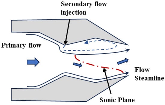
Figure 11.
The dual-throat aerodynamic vectoring nozzle configuration.
- (1)
- Controlling the flow separation in the reentrant is the key to improving the vector deflection angle;
- (2)
- The expansion angle of the reentrant should not exceed 10°;
- (3)
- Increasing the angle of the secondary flow and the angle of convergence of the reentrant can improve the vector angle;
- (4)
- Reducing the length of the reentrant can increase the thrust coefficient and thrust vectoring efficiency.
In the same year, they successfully completed the validation work on the JETF test bed at LRC [73], where the nozzle obtained a vector angle of 15° at a drop pressure ratio of 4, achieving a vector efficiency of 6.1°/1% of the secondary mass flow rate, which is higher than any other fluidic vectoring nozzle reported in the open literature. Meanwhile, a thrust coefficient of 0.968 was attained, with a loss of the thrust coefficient of only 0.5% compared to that of the non-vectorized state. Since then, research on thrust vectoring for secondary jets has begun to focus on dual-throat nozzles.
In 2010, Choon Sik Shin et al. [74] carried out calculations for a double-throat nozzle in the range of 0–10% secondary mass flux. Their findings revealed that the vector angle increased with an increase in the secondary mass flow rate up to approximately 5–6%. However, beyond this range, the vector angle did not continue to increase. Additionally, they observed that the flow coefficient of the nozzle decreased as the secondary flow rate increased. In 2016, Michele Ferlauto et al. [75] investigated the dynamic response of a dual-throat nozzle under both open- and closed-loop control using the compressible URANS equations. They proposed a closed-loop model predictive control for the dual-throat nozzle system based on the ARX model.
Since 2011, Xu’s team has conducted a series of studies aimed at optimizing the structure and performance of the dual-throat nozzle [76]. They have taken the lead in the research of “non-source” dual-throat aerodynamic vector nozzles. Li Ming designed a high-frequency “zero mass jet” dual-throat nozzle, which achieved a maximum vector angle of 24°. Building upon this, they developed a novel Bypass Dual Throat Nozzle (BDTN) using adaptive flow control technology. The BDTN is capable of providing a stable vector angle of up to 23° without the need for an external air source [77]. This advancement significantly enhances the feasibility of jet thrust vectoring.
Notably, in 2019, Lin [78] built upon the work of Xu et al. and proposed a “single-engine inverted V dual nozzle” configuration for the fundamental bypass dual-throat aerodynamic thrust vector nozzle. Lin further designed a single-engine dual BDTN nozzle layout for the “Yu Feng” validation aircraft. The structure of this layout, as depicted in Figure 12, represents the first instance of a fixed-wing vehicle utilizing aerodynamic vectors to achieve pitch, roll, and yaw control without relying on traditional rudders. This successful implementation demonstrates the engineering practicality and application value of BDTN nozzle technology. Immediately after that, Jiang [79] combined the exit shape design with the aerodynamic thrust vector nozzle and proposed a bypassed dual-throat aerodynamic vector nozzle with a parallelogram cross-sectional shape, and conducted a comparative study of the flow field structure and aerodynamic performance with the BDTN which has the rectangular cross-sectional shape. The parallelogram configuration has the same aerodynamic performance change rule as the rectangular configuration, but the parallelogram exit enhances the mixing between the tail jet and the environmental airflow, and the centerline velocity decay of the exit jet is greatly accelerated, which is conducive to the improvement of infrared stealth characteristics.
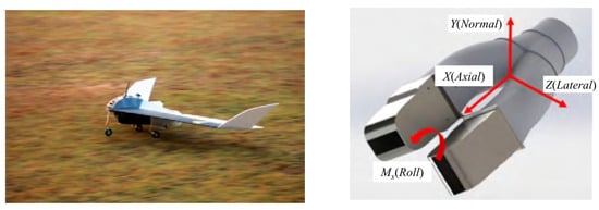
Figure 12.
Flight test of “Yufeng” and layout of the engine design principle [78].
However, there are still some challenges to be addressed in BDTN nozzles. The conventional BDTN structure typically has a V-shaped bypass channel, which can result in a decrease in engine performance. To overcome this issue, Wu et al. [80] proposed an arc-shaped bypass system and applied it to BDTN nozzles, whose figure is shown in Figure 13. The performance of the arc-shaped BDTN was studied through numerical simulations under different conditions. The study found that the arc-shaped BDTN not only achieved high thrust efficiency and thrust coefficient but also significantly reduced total pressure loss compared to BDTN with a V-shaped bypass channel.
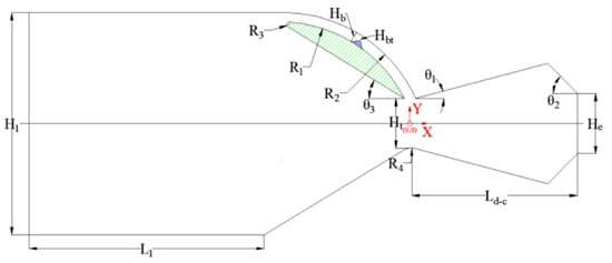
Figure 13.
Geometry model of the improved BDTN proposed by Wu [80].
In additional, Maruyama et al. [81] employed a direct simulation Monte Carlo method to conduct a numerical analysis of the flow within a rocket motor nozzle. Their investigation revealed that a steady thrust deflection of approximately 18° was achieved when the secondary jet’s mass flow rate accounted for 5% of the total fluid. However, it was also observed that random thrust deflections of about 5° occurred when the secondary jet ceased (refer to Figure 14). Maruyama attributed these occurrences to flow field fluctuations after the secondary jet. To address this issue, they improved the nozzle design and discovered that by widening the second throat to 1.50 times the cross-sectional area of the first throat, the unexpected thrust deflection during zero flow of the secondary jet was effectively suppressed (refer to Figure 15).

Figure 14.
Changes in the thrust deflection angle with time (no secondary injection) [81].
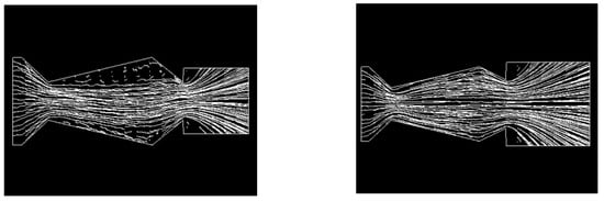
Figure 15.
Flow field in the nozzles without secondary injection [81].
Recently, through the work of Afridi and others [82], the flow characteristics and performance parameters of BDTN were analyzed by varying the bypass angle, nozzle convergence angle, and bypass width. Based on the results and data obtained from simulations, further optimization of the BDTN structure was carried out. The width of the bypass has a significant impact on the vectoring angle, as increasing the bypass width leads to an increase in the mass flow rate of the secondary flow, thereby expanding the vectoring angle. Numerical simulations have shown that the optimal bypass width is around 3.5 mm. Additionally, a smaller bypass angle results in a larger vectoring angle. By decreasing the bypass angle from 90° to 35°, the vectoring angle increases by 6%, while the vectoring efficiency improves by 18%. On the other hand, the convergence angle of the nozzle has almost no effect on the vectoring angle.
5. Fuel Mixing in a Scramjet Engine
Since the early 20th century, the supersonic combustion ramjet engine has been regarded as the most promising propulsion system for hypersonic vehicles. This technology has garnered significant attention from various countries, leading to numerous research projects [83,84,85,86]. However, despite these efforts, the development of this engine still faces several challenges. One major obstacle is the extremely short residence time of gases in the supersonic combustion chamber, which is in the order of milliseconds [87]. Achieving stable combustion relies on the complete fuel jetting and adequate mixing of the incoming flow with the fuel. To address this issue, researchers have proposed a range of methods to enhance supersonic fuel mixing. Detailed studies on various jet parameters have been conducted, and different inlet duct configurations have been explored in order to improve mixing efficiency.
As a matter of fact, the mixing of high-velocity air and fuel jets in a scramjet engine has been taken as a practical engineering object in the 1960s when Broadwell [10] and Zukoski [11] studied the jet problem by theoretical methods. Later, its theory was refined by Schetz [12] and Blllig [13], and began to be applied to the design of supersonic combustion ramjet engines. Up to this point, significant progress has been made in refining the theoretical model of single-orifice fuel jet injection under supersonic incoming flow. Theoretical studies have contributed to a better understanding of the dynamics and behavior of fuel jets in these conditions. This progress has laid a solid foundation for further research and development in the field of scramjet engines.
In 1971, Rogers [88] conducted experimental research on the flow field when hydrogen gas was injected from multi-portholes into a Mach 4.03 airflow. It was found that the jet trajectories from the side-by-side multi-portholes were almost identical to that of a single porthole, but the mixing efficiency was significantly improved. It was also observed that the wider the spacing between the nozzles, the greater the overall mixing efficiency.
In 1992, Arai et al. [89] in their study of liquid foam jets in an air stream with Ma = 2.4 used a longitudinal row strategy of multi-portholes. They measured the penetration length and spray plume diffusion angle using nano shadow graphs and front-lighted pictures, respectively. It was found that the penetration of the jet array increased steadily from front to back for the case of longitudinal rows of spray holes. In the water-only spray test, the penetration of the last jet (12th jet) was more than five times that of the first jet (Figure 16). In addition, the study pointed out that the spacing of the jet injector ports is an important factor affecting the jet penetration force.
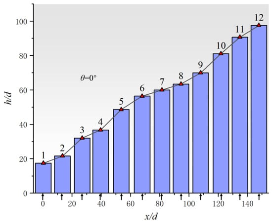
Figure 16.
Penetration of multiple jet injection, arrows represent injection positions. (The x-axis is defined by the ratio of the distance in the main-flow direction to the diameter of the inject hole; the y-axis is defined by the ratio of the penetration depth to the diameter of the inject hole) [89].
Subsequently, extensive research has been conducted on the layout strategy of multi-portholes. Meanwhile, notable contributions were found by Gerdroodbary and his team. Starting in 2015, Gerdroodbary and his team conducted numerous numerical simulation studies focusing on the effects of shock waves in the inlet and air/H2 combination injection on the mixing efficiency of H2 and air. Firstly, they introduced a protruding structure on the opposite side of the fuel injection surface to generate shock waves, which were found to have a significant effect on both single porthole fuel injection and multi-portholes fuel injection. By varying the angle of the shock waves, it was discovered that a lower shock wave angle resulted in higher mixing efficiency of H2 and air [90,91]. Furthermore, Gerdroodbary distributed air as another injection gas, alternating and arranging it longitudinally with the H2 injection portholes. This distribution method showed the best improvement in mixing efficiency when using a single fuel porthole, reaching approximately 116%. However, overall, a greater number of injection ports still demonstrated advantages (as shown in Figure 17 and Figure 18) [92].
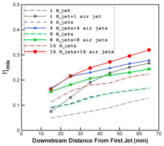
Figure 17.
Comparison of hydrogen mixing for different fuel and air jet arrangements in downstream of fuel and air jets. (The y-axis is defined by mix efficiency) [92].
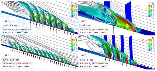
Figure 18.
Flow feature of the fuel and air jet for different fuel and air jet arrangements (The red and blue arrows show the position and direction of the injection of hydrogen and air, respectively) [92].
In 2020, Sharma et al. [93] conducted a detailed numerical study on the case of dual injection portholes, specifically determining the optimal spacing and injection angles of the two ports. It was found that the optimal position of the second port is at the end of the lateral momentum influence region of the first port, where the flow transitions to supersonic. Additionally, reverse fuel injection is more favorable for mixing fuel and air.
However, the additional complexity of the system structure arises when additional air injection portholes are added. Dong et al. [94] proposed a concept of secondary air flow control, where a connected channel is set before and after the fuel injection outlet. This allows a portion of the air, driven by the pressure difference caused by the fuel jet, to enter the channel before the fuel jet and be expelled from the channel after the fuel jet (Figure 19). Their research found that when the upstream hole of the channel is close to the jet and the downstream hole is away from the jet, the variation in the separation region generated by the fuel jet upstream can enhance the mixing process between the fuel and the incoming flow.

Figure 19.
Typical Mach number contour maps for secondary air flow control [94].
There are many studies on the use of geometrically assisted secondary injection. In 2023, Abdollahi et al. [95] conducted a numerical simulation study on the application of squeeze-type nozzles in fuel distribution and combustion mixing processes in supersonic combustion chambers. The study showed that the application of squeeze-type multi-nozzles significantly enhanced the formation of vortices near the injector in the combustion chamber. Injecting secondary fuel flow through the nozzle in supersonic airflow can enhance fuel penetration and diffusion. Increasing the gap between multiple injectors improved fuel mixing performance downstream of the injector by 27%.
Recently, Sekar et al. [96] conducted a study on the influence of secondary ethylene injection behind a curved baffle on the flow dynamics of supersonic combustion in transverse supersonic flow, using a combination of numerical simulations and experiments. The study investigated the effects of injecting secondary ethylene flow behind baffles with different structures under various injection pressures. The results showed that, compared to traditional vertically oriented baffles, the use of curved baffles improved fuel mixing efficiency. The vortex structure near injection port for different spacer structures is shown in Figure 20. It can be found that the variation in curvature angle at the bottom of the baffle led to different vortex structures, thereby affecting the mixing area of the fuel. Furthermore, at a lower injection pressure of 3.5 bar, the impact of baffles with different structures on fuel mixing efficiency was significant, while at a higher injection pressure of 7 bar, the effect of different structures on fuel mixing efficiency was less pronounced.
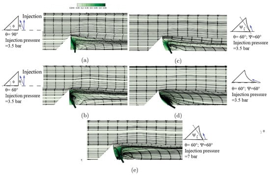
Figure 20.
Vortex structures near the injection port of different baffle structures [96].
In addition, researchers have also conducted extensive studies on the jet itself to improve mixing efficiency, with a notable achievement being the transition from steady jets to pulse jets. In 1994, Randolph et al. [55] discovered the significant influence of pulse jets on penetration depth, which led to pulse jets becoming a research focus in the field of scramjet engines.
Kouchi et al. conducted a series of experiments using high-speed Schlieren and other detection techniques to investigate the penetration and mixing performance of pulse jets in supersonic crossflows. They studied the penetration effects of pulse jets ranging from low-frequency pulses (1 kHz) to high-frequency pulses (50 kHz) [97]. It was found that, under the same mass flow rate condition, the penetration of the pulse jet could be adjusted by changing the pulse frequency, with the optimal frequency falling within the range of 10–20 kHz. Even at a fixed injection pressure, the pulse jet exhibited better mixing performance and greater penetration due to the fluctuations of large-scale vortices in the jet and the shock waves at the head of the jet. It was also suggested that, in order to better compare the effects of pulse jets and steady jets, the average mass flow rate of the pulse jet within one cycle should be consistent with that of the steady jet. This provides a basic guideline for future researchers studying pulse jets.
In 2013, Cutler et al. [98] designed a variable-frequency pulse jet injector and conducted experimental investigations on the influence of transverse pulse jet mixing efficiency in supersonic flows. The study found that pulse frequencies between 10 and 50 kHz were effective in affecting the mixing. Pulse frequencies outside this range resulted in penetration effects similar to those of steady jets.
It is worth noting that in many previous studies, there was limited understanding of the complex flow phenomena and dynamic evolution process in pulse jet flow fields. However, in 2016, Shi et al. [99] utilized the Large Eddy Simulation (LES) method to conduct a detailed investigation of the multiscale vortex structures, complex shock systems, mixing characteristics, and turbulent behavior of pulse jets. They found that due to the pulsation effect, large-scale shear vortices were formed along the interface between the jet and the crossflow, promoting the engulfment and mixing of the jet with the crossflow fluid (Figure 21). They also analyzed the formation of wing shocks, tail shocks, and reflected shocks, as well as their effects on the vortex structures in the flow field. Strong local vorticity and turbulent kinetic energy were observed at the locations where these shocks interacted. This study provided valuable physical insights into the mechanism of interaction between pulse jets and supersonic crossflows.
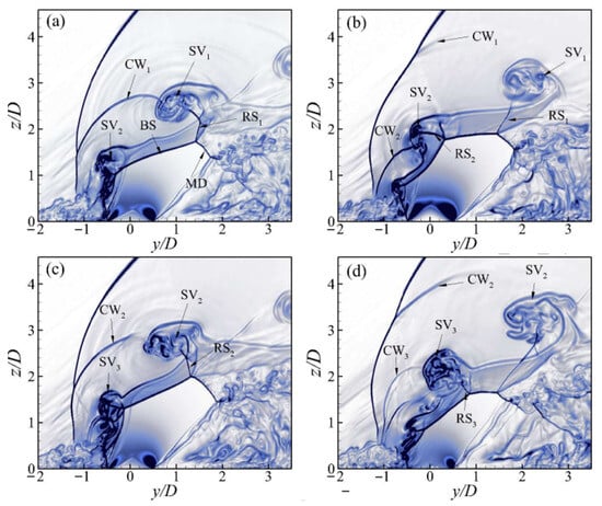
Figure 21.
Numerical Schlieren-like visualization by contours for the phase (a) 0T/4, (b) T/4, (c) 2T/4, and (d) 3T/4 during one pulsed cycle with its period T. (The x-axis is defined by the ratio of the distance in the main-flow direction to the diameter of the inject hole; the y-axis is defined by the ratio of the penetration depth to the diameter of the inject hole) [99].
Zhao et al. [100] further investigated the optimal frequency and found that the enhancement of fuel mixing by pulse jets is closely related to the oscillation frequency of the bow shock, the jet shear layer, and the barrel shock in the flow field. When there is a 40 kHz bow shock frequency of a steady jet, setting the pulse jet frequency to 40 kHz resulted in improved jet mixing efficiency.
During this period, researchers also studied the waveform of pulse jets. It was found that pulse jets with a sinusoidal waveform exhibited better penetration performance [101]. The penetration depth of square wave jets was similar to that of steady jets, but higher turbulence energy was observed near the fuel injection porthole, which means the mixing efficiency of pulse jets was significantly improved [102].
In addition to gas and liquid jet injection, with the development of solid fuel scramjet engines in recent years, the injection of fuel jets consists of solid particles and gas has also become a research focus. Analysis of solid particle behavior in supersonic flow has mainly been seen in recent years, with previous studies primarily focusing on particle motion in low-speed airflow and within the laminar interface of supersonic airflow [34,35,36]. In 2022, Ding [103] developed a computational program for supersonic gas–solid two-phase flow based on the Open FOAM software. This program introduced porosity based on the original Navier–Stokes equations to investigate the flow and mixing characteristics of hydrogen/metal powder fuel in single and twin-jet configurations.
In 2023, Zhao et al. [104] conducted numerical simulations using the Large Eddy Simulation (LES) method to study the gas–solid two-phase jet flow field in supersonic inflow. Their work successfully observed several characteristic phenomena, including the trailing effect of particles and the wave-like structure formed by particle clouds. They also described the distribution of particles of different sizes within the jet vortices, such as shown in Figure 22. However, at present, this research has not yet been developed to the scale of an engine.

Figure 22.
Iso-contours of Q-criterion and distribution of particles in the vortex. (a) shows the particle size and (b) shows the particle velocity [104].
6. Jet Noise Control
During the operation of an aero-engine as well as a rocket engine, the high-pressure, high-temperature gas generated in the combustion chamber is injected at supersonic speeds through the Laval nozzle into the surrounding low-temperature, relatively static environment. In this process, the gas jet mixes intensively with the surrounding medium, which triggers strong turbulent pulsations in the jet boundary layer, propagates in the form of pressure waves in all directions, and generates powerful jet aerodynamic noise [105]. Noise of this intensity can cause damage to personnel and delicate instruments. In previous studies, researchers have proposed various measures to suppress aerodynamic noise, such as using chevron nozzles [106,107] or corrugated nozzles [108,109] to optimize the engine configuration. However, these configurations inevitably lead to performance losses in the engine, and these losses persist throughout the entire flight process. Therefore, more flexible methods for jet noise suppression gained attention.
Research on jet noise suppression started very early. In 1954, Powell [110] attempted to reduce engine noise by injecting a secondary jet at the nozzle exit to alter the velocity distribution at the nozzle exit while maintaining thrust. However, subsequently, other researchers conducting experiments found that a significant amount of water was required to effectively reduce the engine noise through water injection. In 1971, Manson et al. [111,112] attempted to replace the water injection with liquid foam to reduce the water consumption. Experimental results showed that foam injection had excellent absorption effects in the high-frequency range, achieving up to 90% reduction in noise and a maximum noise reduction of 10 dB. However, it also required a mass flow rate close to or equal to the primary flow. For ground-based noise reduction processes in launch vehicles, the flow rate is not a limiting constraint. When the ratio of water mass flow rate to engine jet mass flow rate is approximately 100% to 200%, noise reduction of around 8 to 12 dB can be achieved [113].
However, it was later realized that there may be differences between free jet noise tests conducted on the ground and the actual noise experienced during flight. Forward flight may lead to a reduction in mixed noise, so it cannot be inferred that the same magnitude of water is needed for noise reduction during actual flight [114]. Additionally, researchers have found that the temperature of the heated jet has a significant impact on noise emission, depending on the Mach number. At low jet velocities, increasing the temperature results in an increase in the sound pressure level. However, at high jet exit velocities, as long as the jet velocity remains constant, lower noise can be achieved by heating the jet [115,116].
Meanwhile, research on low-flow noise reduction has also been ongoing. In order to improve applicability in aircraft, efforts have been made to reduce the size of the porthole for jets and increase the injection pressure. In 2002, Krothapalli et al. [117] conducted an experiment to study the injection of fine mist water droplets and air into the shear layer of primary flow, with a very low mass flow rate ratio (below 2%). They found that the microjet injection scheme significantly reduced the noise, resulting in a reduction of approximately 1.5 dB in the far-field Overall Sound Pressure Level (OASPL). Additionally, at the peak radiation angle, the measured OASPL significantly decreased by 6 dB when water injection was applied (Figure 23). Krothapalli suggested that this could be due to the suppression of large-scale vortices by microjets, as large-scale vortices are the main source of low-frequency components in mixed noise.
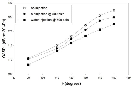
Figure 23.
Far-field directivity of a 0.9 Mach number mainstream while nozzle temperature ratio = 3. (The x-axis is defined by the angle with the nozzle axis, the y-axis is defined by Overall Sound Pressure Level (OASPL)) [117].
Krothapalli’s research demonstrated the significant potential of microjet noise reduction technology. In the following years, researchers conducted numerous experimental studies to further investigate the effects of water injection on engine noise, including the mass flow rate, pressure, and the influence of cold and hot jets [113,118]. Regarding gas injection, detailed research has also been conducted on factors such as injection angle, pressure, and the number of injection portholes [119,120,121,122,123].
It is worth mentioning that in 2005, experiments were conducted on the F404-GE-402 jet engine using this microjet noise reduction technology. During the experiment, the mass flow rate ratio of the microjets ranged from 8% to 11%. A reduction of 2–3 dBA was observed in the peak radiation direction, and reductions of up to 5 dBA were observed in other directions [124].
During this period, numerical simulation methods such as Reynolds-Averaged Navier–Stokes (RANS) and Large Eddy Simulation (LES) have become more mature, with LES in particular demonstrating good accuracy in resolving vortices in the flow field. Researchers have utilized these methods to extensively analyze the flow characteristics of jet noise reduction. In 2004, Kandula et al. [125] conducted a numerical simulation study on the generation and propagation of noise in supersonic duct flows. They used CFD to calculate the near-field sound sources, while the far-field noise was computed using the Kirchhoff surface integral formulation. The results obtained were in good agreement with previous experimental results.
In 2010, Xu et al. [126] made modifications to Kandula’s theoretical model and conducted a study on microjet noise reduction of rocket engines using the finite volume method and water injection experiments. They found that the mass flow rate ratio of water to gas jet, denoted as λ, is a crucial parameter that determines the effectiveness of water injection for noise reduction. When λ is below a certain value, the OASPL decreases as λ increases. However, when λ exceeds the value, the noise reduction efficiency decreases and additional noise generated by water injection can be observed, the exact changes are given in Figure 24.
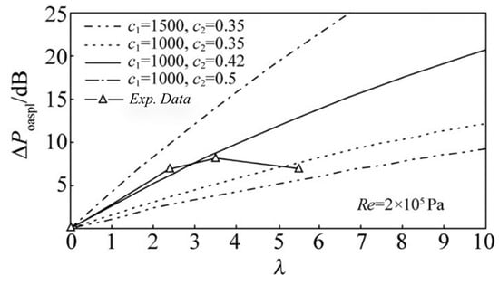
Figure 24.
Comparison of calculated and experimental results for ΔPoaspl with λ. (The x-axis is defined by the mass flow rate ratio of water to gas jet; the y axis is defined by OASPL) [126].
In 2013, McLaughlin and his team [127] proposed a fluid insert nozzle structure embedded in the inner wall of the engine nozzle (Figure 25). Experimental results showed that this structure achieved significant noise reduction. A reduction of 5 dB was obtained with a jet flow rate ratio of 4%. In the following years, McLaughlin’s team conducted detailed experimental and numerical studies on this structure, investigating the effects of parameters such as nozzle arrangement, pressure ratio, total temperature ratio, and Mach number on jet noise reduction [128,129,130,131,132,133,134]. In 2017, McLaughlin’s team used numerical simulation methods to explore the effects of two-directional asymmetric injection and three-directional symmetric injection. They found that both structures achieved the same level of noise reduction, indicating that noise reduction depends on the angular separation of at least two jet injection directions. However, the specific mechanism behind this phenomenon is still not fully understood [135].
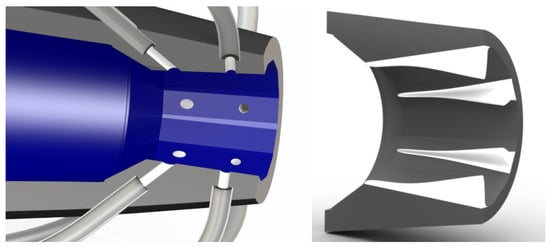
Figure 25.
Schematic drawing comparison of the nozzle with six corrugations [127].
In 2018, Coderoni et al. [136] conducted a noise reduction study on GE F400-series engines and investigated the fluid insert method proposed by McLaughlin’s team using LES. As shown in Figure 26, they found that the injection of the secondary fluid breaks down the shock cell into smaller structures with different directions and intensities, which directly reduces the intensity of noise related with broadband shock.
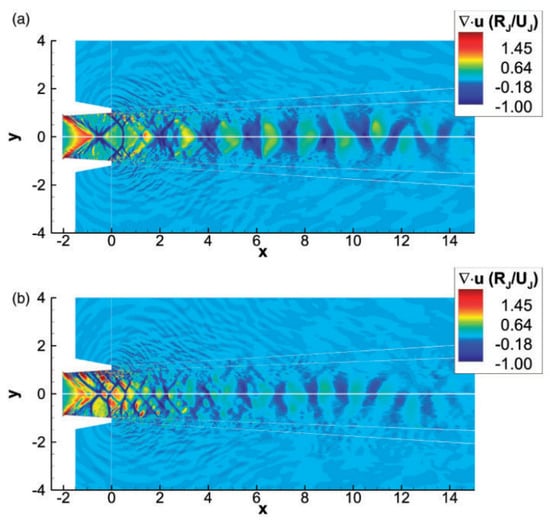
Figure 26.
LES instantaneous dilatation contours’ comparison between (a) round nozzle baseline nozzle and (b) nozzle with fluidic injection [136].
Subsequently, Coderoni conducted further research comparing the effects of heated and cold jets on engine noise [137]. In this study, numerical simulations were performed using both LES and RANS methods, and the results showed good agreement between the two methods and were also consistent with previous experimental data. The computational results showed that the effectiveness of the heated jet mainly changes the spreading rate of jet, particularly the Turbulent Kinetic Energy (TKE). However, as the total pressure of the jet remains constant, there is little change in the Mach number within the flow field, thus the increase in jet temperature has almost no effect on the shock cell. Additionally, in this study, Coderoni used the Q-criterion to identify larger turbulent structures in the flow field (Figure 27) and found that the introduction of the jet reduced the presence of these large turbulent structures in the exhaust gas, thereby reducing the intensity of mid-to-low-frequency noise.
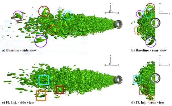
Figure 27.
Q-criterion iso-surfaces base on for the nozzle with and without injectors. Circles (for the baseline case) and squares (for the fluid injection case) are added to identify the larger structures that are more distant from the jet axis [137].
In recent years, Prasad and his team [138,139] utilized a combination of Doak’s Momentum Potential Theory and Spectral Proper Orthogonal Decomposition to LES simulations, which was used to analyze the flow field of fluid inserts. Their findings supported Coderoni’s previous conclusion regarding the weakness of large-scale turbulence caused by the jet. Furthermore, their observations indicated that fluid inserts negatively impact the radiation efficiency of wave packets primarily due to the disruption of large-scale structures and alterations to the Kelvin–Helmholtz instability.
7. Other Application
Furthermore, due to the outstanding effects of active secondary injection in the aforementioned aspects, researchers also conducted various other attempts to apply jets in engines.
In 2001, T.D. Smith [140] conducted a study on the plume variation of pulsed injection in a convergent-divergent nozzle using numerical simulations and experiments. The numerical methods were applied to simulate scaled-down turbofan engines, full-scale ground test engines, and high bypass ratio engines. The results of the study demonstrated that pulsed injection significantly reduces the length of the central gas plume compared to steady-state injection. The experimental engine and the wade flow static temperature cloud maps are displayed in Figure 28.

Figure 28.
The experimental engine and the wade flow static temperature cloud maps (steady-state on the top right, pulsed-average on the bottom right) [140].
In the field of solid rocket motors, the nozzle is often protected from heat by using ablative cooling. In 2009, Thakre et al. [141] conducted a study where they injected a lower temperature gas upstream of the throat to affect the nozzle boundary layer. This gas was generated from the reaction of a small amount of combustion gases and an ablative material. They performed numerical simulations under different injection temperatures, angles, and velocities to identify and quantify various fundamental mechanisms influencing the effectiveness of the nozzle boundary layer control system. They found that through this injection method, even under high-pressure conditions, the erosion rate of the nozzle boundary layer could be negligible (Figure 29), which is primarily attributed to the low temperature of the injected gas and the reduced concentration of oxidizing species near the nozzle surface.
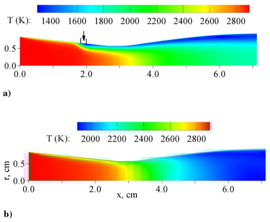
Figure 29.
Distribution of temperature in nozzle interior: (a) with injection, and (b) without injection (temperature of mainstream is 3000 K, combustion chamber pressure is 6:9 MPa, and temperature of injection gas is 1200 K, surface reactions, conductive wall) [141].
In 2014, Zheng et al. [142] combined a generalized one-dimensional flow model and an isochoric cycle model to establish a corresponding mathematical model, studying the propulsion performance of pulse detonation engines with secondary flow injection. The results indicated that, in steady flow conditions, if the geometric configuration of the nozzle remains unchanged, injecting secondary flow can enhance the performance of the nozzle when the nozzle pressure drop ratio is below a critical value.
In 2017, Cai et al. [143] conducted experimental and numerical studies to investigate the effects on the combustion performance of hybrid rocket motor with injecting thermally decomposed hydrogen peroxide into the post-combustion chamber of a hybrid rocket motor. They mainly analyzed the injection diameter, injection angle, and number of portholes. It was found that injecting the post-combustion chamber jet can improve the engine’s combustion efficiency and specific impulse, but it does not increase the burning rate and temperature of the solid propellant. At the given diameter of the engine, the maximum combustion efficiency was achieved when eight portholes with a 120° circumferential arrangement were used. The distribution of components in the flow field after injection is shown in Figure 30.

Figure 30.
Distribution of components in the flow field during oxidizer injection in the post chamber of hybrid rocket motor (with: (a): O2; (b): C4H6) [143].
In the same year, Lv [144] aimed to increase the performance of the nozzle used in wide-speed range aircraft engine and prevent thrust loss caused by overexpansion. They discovered that inducing separation in the straight edge of the nozzle during jet injection is an effective method. Numerical studies showed that this method significantly improves the engine’s performance. When the pressure ratio was 10, the increase in thrust coefficient, lift, and pitching moment reached 3.16%, 29.43%, and 41.67%, respectively.
In 2019, Zhang [145] conducted an analysis of the infrared radiation characteristics of a single-sided expansion nozzle with secondary flow. For the throat aerodynamic vector nozzle, the study investigated the effects of the secondary flow pressure ratio, injection angle, and relative area ratio on the total radiation intensity within the detection planes of XOY (zenith angle) and XOZ (azimuth angle). The results are shown in Figure 31, which indicated that as the secondary flow pressure ratio increased, both the zenith angle range and the azimuth angle range showed a decreasing trend in total radiation intensity, with maximum decreases of 14.49% and 16.38%, respectively.
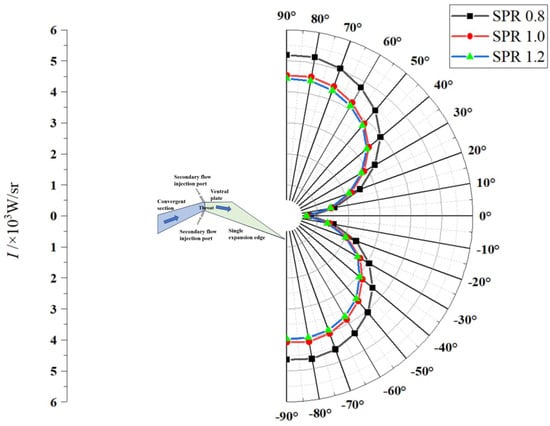
Figure 31.
The variation of radiation intensity with zenith angle at different secondary flow pressure ratios, and the blue and green areas represent the position of the nozzle structure and the gas relative to the measurement point, respectively [145].
8. Conclusions
Based on the aforementioned sections, the typical applications of the secondary injection in aerospace propulsion systems are summarized and organized in Table 1, along with the advantages, disadvantages, and important milestones in the development of different technologies, while a corresponding literature statistical analysis is also conducted in Figure 32 and Figure 33.

Table 1.
Summary of typical applications of active secondary jets in aerospace propulsion systems.

Figure 32.
Comparison of publication quantity for typical applications.
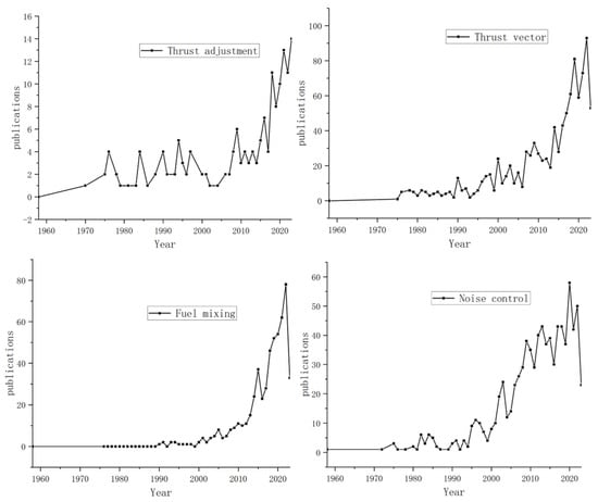
Figure 33.
Statistics of publications on typical applications. (The x-axis represents years, while the y-axis represents the number of publications).
In summary, since the 1940s, active secondary jet technology has developed many promising applications in the aerospace field, and in recent years, it has been receiving increasing attention. This article reviews the past theoretical and experimental research on secondary jets and discusses their applications in aerospace engines, including thrust adjustment, thrust vectoring, fuel mixing, and noise control. It also briefly introduces other promising explorations in the field of engines.
- (1)
- The use of active secondary injection for thrust regulation offers advantages such as simple structure, lightweight, and absence of component erosion compared to mechanical adjustment methods. This makes it particularly suitable for rocket engines, especially solid rocket engines. However, the range of thrust adjustment with secondary jet is still limited by the large flow rate of the secondary jet. Therefore, research on the regulation of thrust magnitude in throat-jet is relatively limited, accounting for approximately 6% of the total publication quantity for the four typical applications. However, the combination of a pintle structure and secondary jet may lead to further development of this technology. It not only enables effective thrust adjustment, but also ensures longer operation because of protection of the secondary jet on the pintle surface. However, the mechanical structure resulting from this combination will be a challenge that needs to be optimized in the next step.
- (2)
- Thrust vectoring is currently the most prominent application of active secondary injection in the aerospace propulsion field. Especially after the introduction of the dual-throat nozzle in 2003, the number of relevant publications has rapidly increased. The introduction of a passive bypass jet scheme further simplifies the system structures of the secondary flow and achieves a thrust vector angle above 24°, which is far surpassing other thrust vectoring technologies (around 15°). However, some studies have indicated that the dual-throat nozzle may experience uncontrolled small vector angles in certain cases, which may be caused by fluctuations in the engine flow field. This issue can be effectively addressed by increasing the area of the second throat, but the impact on the thrust vectoring capability after expanding the second throat is not yet clear.
- (3)
- For fuel mixing, the use of multi-portholes injection can effectively improve the mixing efficiency of fuel and air, and some studies indicate that if parts of the multi-portholes are used to inject air, the air and fuel can mix with each other in the strong turbulence structure downstream of the jet, which achieves an efficiency improvement of 116%. However, additional air sources will inevitably cause redundancy in the system structure. Meanwhile, bypass structures similar to those used in thrust vectoring studies have been shown to enhance the mixing efficiency of individual fuel injection porthole, which means the application of this approach in multi-porthole jets is also promising, especially when applied to multi-portholes, as it may further enhance mixing efficiency while simplifying the structure. On the other hand, pulsed fuel jets can also significantly enhance the mixing efficiency, but further research is needed to characterize the features and related mechanisms affecting fuel mixing in pulsed jet flow fields. In fact, many technologies that promote fuel mixing are not mutually exclusive. Therefore, in the future, it can be explored to combine multiple techniques in jet research to further uncover the potential of jets in fuel mixing.
- (4)
- Normally, engines generate large noise during operation, which can pose a threat to personnel and the delicate components. Current research indicates that noise can be effectively suppressed by utilizing secondary jets on the nozzle wall. However, in fact, the publication quantity indicates that before the emergence of micro-jet noise reduction technology in 2002, traditional jet noise reduction techniques required a jet flow rate near 100% of the primary flow, making it difficult to have practical engineering significance. The development of micro-jet noise reduction technology greatly promoted the advancement of aerospace propulsion system noise reduction techniques. The fluidic embedded nozzle technology proposed in 2013 has attracted wide attention from scholars due to its lower flow consumption and better noise reduction effect, which can obtain a reduction of 5 dB with a jet flow rate ratio of 4%. Currently, the structural optimization of fluidic embedded nozzle technology and related mechanism analysis still require further research.
- (5)
- In recent years, there have been numerous attempts to explore other applications of secondary jets, but it is worth noting is that in many applications, the injection positions of the secondary jets in the engine are actually highly overlapped. For instance, in applications such as conical nozzle thrust vectoring and noise suppression, the jet positions mainly concentrate in the expansion section of the nozzle. For applications such as thrust vectoring in dual-throat nozzles, thrust adjustment, and infrared radiation suppression, the jet positions primarily focus on the throat section of the nozzle. It is indicated that secondary jets at a specific position may bring multiple benefits, but there has been little research systematically considering the comprehensive effects of jet parameters on different applications. Instead, the optimization has been limited to a single application. In the future, it may be worthwhile to analyze and optimize jet parameters for multiple applications, which could further reveal the potential of active secondary jets in engine applications.
Author Contributions
Conceptualization, H.G. and H.Z.; methodology, H.G. and H.Z.; project administration, H.G. and H.Z.; validation, H.Z.; formal analysis, H.G.; investigation, H.G.; writing—original draft preparation, H.G.; writing—review and editing, H.Z.; visualization, H.G. and J.S.; supervision, H.Z. and H.T.; funding acquisition, H.Z., H.T. and G.C. All authors have read and agreed to the published version of the manuscript.
Funding
Fundamental Research Funds for the Central Universities. YWF-22-L-1181.
Data Availability Statement
The data presented in this study are available on request from the corresponding author.
Conflicts of Interest
The authors declare no conflict of interest.
References
- Deere, K. Summary of fluidic thrust vectoring research at NASA Langley Research Center. In Proceedings of the 21st AIAA Applied Aerodynamics Conference, Orlando, FL, USA, 23–26 June 2003; p. 3800. [Google Scholar]
- Lian, Y. Fluidic thrust vectoring techniques research. Aircr. Des. 2008, 28, 19–24. [Google Scholar]
- Ali, A.; Rodriguez, C.; Neely, A.; Young, J. Combination of fluidic thrust modulation and vectoring in a 2D nozzle. In Proceedings of the 48th AIAA/ASME/SAE/ASEE Joint Propulsion Conference & Exhibit, Atlanta, GA, USA, 30 July–1 August 2012; p. 3780. [Google Scholar]
- Guo, C.; Wei, Z.; Xie, K.; Wang, N. Thrust control by fluidic injection in solid rocket motors. J. Propul. Power 2017, 33, 815–829. [Google Scholar] [CrossRef]
- Das, A.K.; Acharyya, K.; Mankodi, T.K.; Saha, U.K. Fluidic Thrust Vector Control of Aerospace Vehicles: State-of-the-Art Review and Future Prospects. J. Fluids Eng. 2023, 145, 080801. [Google Scholar] [CrossRef]
- Choubey, G.; Yuvarajan, D.; Huang, W.; Shafee, A.; Pandey, K. Recent research progress on transverse injection technique for scramjet applications-a brief review. Int. J. Hydrogen Energy 2020, 45, 27806–27827. [Google Scholar] [CrossRef]
- Salehian, S.; Mankbadi, R.R. A review of aeroacoustics of supersonic jets interacting with solid surfaces. In Proceedings of the AIAA SciTech 2020 Forum, Orlando, FL, USA, 6–10 January 2020; p. 0006. [Google Scholar]
- Chang-Lu, H. Aufrollung eines zylindrischen Strahles durch Querwind. In The Roll-Up of a Cylindrical Jet in a Cross Flow; USAF-AFRL 73-0131; Nagaraja, K.S., Schrade, H.O., Eds. and Translators; University of Göttingen: Göttingen, Germany, 1973. [Google Scholar]
- Ehrich, F.F. Penetration and deflection of jets oblique to a general stream. J. Aeronaut. Sci. 1953, 20, 99–104. [Google Scholar] [CrossRef]
- Broadwell, J.E. Analysis of the fluid mechanics of secondary injection for thrust vector control. AIAA J. 1963, 1, 1067–1075. [Google Scholar] [CrossRef]
- Zukoski, E.E.; Spaid, F.W. Secondary injection of gases into a supersonic flow. AIAA J. 1964, 2, 1689–1696. [Google Scholar] [CrossRef]
- Schetz, J.A.; Billig, F.S. Penetration of gaseous jets injected into a supersonic stream. J. Spacecr. Rocket. 1966, 3, 1658–1665. [Google Scholar] [CrossRef]
- Blllig, F.; Orth, R.; Lasky, M. A unified analysis of gaseous jet penetration. AIAA J. 1971, 9, 1048–1058. [Google Scholar] [CrossRef]
- Santiago, J.G.; Dutton, J.C. Velocity measurements of a jet injected into a supersonic crossflow. J. Propul. Power 1997, 13, 264–273. [Google Scholar] [CrossRef]
- Kumar, A.; Rudy, D.; Drummond, J.; Harris, J. Experiences with explicit finite-difference schemes for complex fluid dynamics problems on STAR-100 and CYBER-203 computers. NASA STI/Recon Tech. Rep. A 1982, 82, 43251. [Google Scholar]
- MacCormack, R.W. A numerical method for solving the equations of compressible viscous flow. AIAA J. 1982, 20, 1275–1281. [Google Scholar] [CrossRef]
- Kumar, A. Three-Dimensional Inviscid Analysis of the Scramjet Inlet Flowfield. J. Aircr. 1982, 19, 892–893. [Google Scholar] [CrossRef]
- Smith, R.E. Two-Boundary Grid Generation for the Solution of the Three Dimensional Compressible Navier-Stokes Equations; NASA: Hampton, VA, USA, 1981.
- Peyret, R.; Viviand, H.; Smolderen, J. Computation of viscous compressible flows based on the Navier-Stokes equations. NASA STI/Recon Tech. Rep. N 1975, 76, 11380. [Google Scholar]
- Pulliam, T.H.; Steger, J.L. Implicit finite-difference simulations of three-dimensional compressible flow. AIAA J. 1980, 18, 159–167. [Google Scholar] [CrossRef]
- Heister, S.; Karagozian, A. Gaseous jet in supersonic crossflow. AIAA J. 1990, 28, 819–827. [Google Scholar] [CrossRef]
- Billig, F.S.; Orth, R.; Schetz, J. The Interaction and Penetration of Gaseous Jets in Supersonic Flow; NASA: Silver Spring, MD, USA, 1969.
- Wilcox, D.C. Comparison of two-equation turbulence models for boundary layers with pressure gradient. AIAA J. 1993, 31, 1414–1421. [Google Scholar] [CrossRef]
- Wilcox, D.C. Turbulence Modeling for CFD; DCW industries: La Canada, CA, USA, 1998; Volume 2. [Google Scholar]
- Tam, C.-J.; Baurle, R.; Gruber, M. Numerical study of jet injection into a supersonic crossflow. In Proceedings of the 35th Joint Propulsion Conference and Exhibit, Los Angeles, CA, USA, 20–24 June 1999; p. 2254. [Google Scholar]
- Viti, V.; Schetz, J.; Neel, R. Comparison of first and second order turbulence models for a jet/3D ramp combination in supersonic flow. In Proceedings of the 43rd AIAA Aerospace Sciences Meeting and Exhibit, Reno, NV, USA, 10–13 January 2005; p. 1100. [Google Scholar]
- Viti, V.; Neel, R.; Schetz, J.A. Detailed flow physics of the supersonic jet interaction flow field. Phys. Fluids 2009, 21, 046101. [Google Scholar] [CrossRef]
- Peterson, D.M.; Candler, G.V. Hybrid Reynolds-averaged and large-eddy simulation of normal injection into a supersonic crossflow. J. Propul. Power 2010, 26, 533–544. [Google Scholar] [CrossRef]
- Won, S.-H.; Jeung, I.-S.; Parent, B.; Choi, J.-Y. Numerical investigation of transverse hydrogen jet into supersonic crossflow using detached-eddy simulation. AIAA J. 2010, 48, 1047–1058. [Google Scholar] [CrossRef]
- Kawai, S.; Lele, S.K. Large-eddy simulation of jet mixing in supersonic crossflows. AIAA J. 2010, 48, 2063–2083. [Google Scholar] [CrossRef]
- Bender, E.; Miller, D.; Smith, B.; Yagle, P.; Vermeulen, P.; Walker, S. Simulation of pulsed injection in a cross flow using 3-D unsteady CFD. In Proceedings of the Fluids 2000 Conference and Exhibit, Denver, CO, USA, 19–22 June 2000; p. 2318. [Google Scholar]
- Linden, P.; Turner, J. The formation of ‘optimal’ vortex rings, and the efficiency of propulsion devices. J. Fluid Mech. 2001, 427, 61–72. [Google Scholar] [CrossRef]
- McManus, K.; Magill, J. Separation control in incompressible and compressible flows using pulsed jets. In Proceedings of the Fluid Dynamics Conference, New Orleans, LA, USA, 17–20 June 1996; p. 1948. [Google Scholar]
- Campolo, M.; Salvetti, M.V.; Soldati, A. Mechanisms for microparticle dispersion in a jet in crossflow. AIChE J. 2005, 51, 28–43. [Google Scholar] [CrossRef]
- Agati, G.; Borello, D.; Camerlengo, G.; Rispoli, F.; Sesterhenn, J. DNS of an oblique jet in a particle-laden crossflow: Study of solid phase preferential concentration and particle-wall interaction. Flow Turbul. Combust. 2020, 105, 517–535. [Google Scholar] [CrossRef]
- Park, J.; Park, H. Particle dispersion induced by vortical interactions in a particle-laden upward jet with a partial crossflow. J. Fluid Mech. 2021, 915, A5. [Google Scholar] [CrossRef]
- Schetz, J.; Kush, E., Jr.; Joshi, P. Wave phenomena in liquid jet breakup in a supersonic crossflow. AIAA J. 1980, 18, 774–778. [Google Scholar] [CrossRef]
- Im, K.-S.; Lin, K.-C.; Lai, M.-C. Spray atomization of liquid jet in supersonic cross flows. In Proceedings of the 43rd AIAA Aerospace Sciences Meeting and Exhibit, Reno, NV, USA, 10–13 January 2005; p. 732. [Google Scholar]
- Im, K.-S.; Lin, K.-C.; Lai, M.-C.; Chon, M. Breakup modeling of a liquid jet in cross flow. Int. J. Automot. Technol. 2011, 12, 489–496. [Google Scholar] [CrossRef]
- Feng, L.; Fuguo, L.; Weidong, L.; Kai, Z.; Changsheng, W.; Yiwei, X. Breakup characteristics of liquid jet in supersonic cross flow. J. Beijing Univ. Aeronaut. Astronaut. 2015, 41, 2356–2362. (In Chinese) [Google Scholar]
- Napior, J.; Garmy, V. Controllable solid propulsion for launch vehicle and spacecraft application. In Proceedings of the 57th International Astronautical Congress, Valencia, Spain, 2–6 October 2006; p. C4.2.04. [Google Scholar]
- Casiano, M.J.; Hulka, J.R.; Yang, V. Liquid-propellant rocket engine throttling: A comprehensive review. J. Propul. Power 2010, 26, 897–923. [Google Scholar] [CrossRef]
- Ostrander, M.; Bergmans, J.; Thomas, M.; Burroughs, S. Pintle motor challenges for tactical missiles. In Proceedings of the 36th AIAA/ASME/SAE/ASEE Joint Propulsion Conference and Exhibit, Las Vegas, NV, USA, 24–28 July 2000; p. 3310. [Google Scholar]
- Burroughs, S. Status of army pintle technology for controllable thrust propulsion. In Proceedings of the 37th Joint Propulsion Conference and Exhibit, Salt Lake City, UT, USA, 8–11 July 2001; p. 3598. [Google Scholar]
- Heo, J.; Jeong, K.; Sung, H.-G. Numerical study of the dynamic characteristics of pintle nozzles for variable thrust. J. Propul. Power 2015, 31, 230–237. [Google Scholar] [CrossRef]
- Martin, A. The aerodynamic variable nozzle. J. Aeronaut. Sci. 1957, 24, 357–362. [Google Scholar] [CrossRef]
- Gunter, F.L.; Fahrenholz, F. Final report on a study of rocket thrust control by gas injection. Mass. Inst. Technol. Nav. Supersonic Lab. Tech. Rep. 1961, 448. [Google Scholar]
- Zumwalt, G.; Jackomis, W.N. Aerodynamic throat nozzle for thrust magnitude control of solid fuel rockets. Am. Rocket Soc. J. 1962, 32, 1934–1936. [Google Scholar]
- Betts, E.; Frederick, R. A historical systems study of liquid rocket engine throttling capabilities. In Proceedings of the 46th AIAA/ASME/SAE/ASEE Joint Propulsion Conference & Exhibit, Nashville, TN, USA, 25–28 July 2010; pp. 2010–6541. [Google Scholar]
- Dressler, G. Summary of deep throttling rocket engines with emphasis on Apollo LMDE. In Proceedings of the 42nd AIAA/ASME/SAE/ASEE Joint Propulsion Conference & Exhibit, Sacramento, CA, USA, 9–12 July 2006; pp. 2006–5220. [Google Scholar]
- Miller, D.; Catt, J. Conceptual development of fixed-geometry nozzles using fluidic injection for throat area control. In Proceedings of the 31st Joint Propulsion Conference and Exhibit, San Diego, CA, USA, 10–12 July 1995; p. 2603. [Google Scholar]
- Walker, S.; Walker, S. Lessons learned in the development of a national cooperative program. In Proceedings of the 33rd Joint Propulsion Conference and Exhibit, Seattle, WA, USA, 6–9 July 1997; pp. 1997–3348. [Google Scholar]
- Weber, Y.; Bowers, D. Advancements in exhaust system technology for the 21st century. In Proceedings of the 34th AIAA/ASME/SAE/ASEE Joint Propulsion Conference and Exhibit, Cleveland, OH, USA, 13–15 July 1998; p. 3100. [Google Scholar]
- Catt, J.; Miller, D.; Giuliano, V. A static investigation of fixed-geometry nozzles using fluidic injection for throat area control. In Proceedings of the 31st Joint Propulsion Conference and Exhibit, San Diego, CA, USA, 10–12 July 1995; pp. 1995–2604. [Google Scholar]
- Randolph, H.; Chew, L.; Johari, H. Pulsed jets in supersonic crossflow. J. Propul. Power 1994, 10, 746–748. [Google Scholar] [CrossRef]
- Abramovich, G.N. The Theory of Turbulent Jets; MassachusettsInst. of Technology Press: Cambridge, MA, USA, 1963; Chapter 12, Section 4. [Google Scholar]
- Baruzzini, D.; Domel, N.; Miller, D. Pulsed injection flow control for throttling in supersonic nozzles—A computational fluid dynamics design study. In Proceedings of the 37th AIAA Fluid Dynamics Conference and Exhibit, Miami, FL, USA, 25–28 June 2007; p. 4215. [Google Scholar]
- Domel, N.; Baruzzini, D.; Miller, D. Pulsed Injection Flow Control for Throttling in Supersonic Nozzles—A Computational Fluid Dynamics Based Performance Correlation. In Proceedings of the 37th AIAA Fluid Dynamics Conference and Exhibit, Miami, FL, USA, 25–28 June 2007; p. 4214. [Google Scholar]
- Kan, X.; Yu, L.; Bai, W.Y. Investigation of ring aerodynamic throat for solid rocket motor. J. Aerosp. Power 2009, 24, 2631–2636. (In Chinese) [Google Scholar]
- Kan, X.; Bai, W.Y.; Yu, L. Simulation for the two-phase flow aerodynamic throat of solid rocket motors. J. Propuls. Technol. 2010, 31, 56–60. (In Chinese) [Google Scholar]
- Kan, X.; Bo, L.; Chao, G.C.; Fei, W.N. Thrust Control Features for Aerodynamic Throat for Solid Rocket Motor. J. Propuls. Technol. 2015, 36, 194–199. (In Chinese) [Google Scholar]
- Minghui, Y. Research on Thrust Characteristics of Solid Rocket Motor Based on the Catalytic &Oxidative Secondary Flow Injection. Master’s Thesis, Beijing Institute of Technology, Beijing, China, 2016. [Google Scholar]
- Chao, G.C. Research on Dynamic Characteristics of Fluidic Nozzle Throat in Solid Rocket Motor. Ph.D Thesis, Beijing Institute of Technology, Beijing, China, 2018. [Google Scholar]
- Yan, D.; Wei, Z.; Xie, K.; Wang, N. Simulation of thrust control by fluidic injection and pintle in a solid rocket motor. Aerosp. Sci. Technol. 2020, 99, 105711. [Google Scholar] [CrossRef]
- Yang, Z.; Xie, K.; Li, X.; Yan, D.; Li, J.; Wang, N. The Effect of Fluidic Pintle Nozzle on the Ablative Features. In Liutex and Third Generation of Vortex Identification: Workshop from Aerospace and Aeronautics World Forum 2021; Springer Nature: Singapore, Singapore, 2023; pp. 327–344. [Google Scholar]
- Hsia, H.T.-S.; Karamcheti, K.; Seifert, H.S. Shocks induced by secondary fluid injection. J. Spacecr. Rocket. 1965, 2, 67–72. [Google Scholar] [CrossRef]
- Martin, C.L.; Powers, L. Feasibility Study of LITVC for Shuttle SRB; National Aeronautics and Space Administration, Marshall Space Flight Center: Huntsville, AL, USA, 1981.
- Deere, K. PAB3D simulations of a nozzle with fluidic injection for yaw thruseronautics and Space Admint-vector control. In Proceedings of the 34th AIAA/ASME/SAE/ASEE Joint Propulsion Conference and Exhibit, Cleveland, OH, USA, 13–15 July 1998; pp. 1998–3254. [Google Scholar]
- Balu, R.; Marathe, A.; Paul, P.; Mukunda, H. Analysis of performance of a hot gas injection thrust vector controlsystem. J. Propuls. Power 1991, 7, 580–585. [Google Scholar] [CrossRef]
- Azevedo, D. Measured thrust losses associated with secondary air injection through nozzle walls. J. Propuls. Power 1993, 9, 43–50. [Google Scholar] [CrossRef]
- Yagle, P.; Miller, D.; Ginn, K.; Hamstra, J. Demonstration of fluidic throat skewing for thrust vectoring in structurally fixed nozzles. J. Eng. Gas Turbines Power 2001, 123, 502–507. [Google Scholar] [CrossRef]
- Deere, K.; Berrier, B.; Flamm, J.; Johnson, S. A Computational Study of a Dual Throat Fluidic Thrust Vectoring Nozzle Concept. In Proceedings of the 41st AIAA/ASME/SAE/ASEE Joint Propulsion Conference & Exhibit, Tucson, AZ, USA, 10–13 July 2005; p. 3502. [Google Scholar]
- Flamm, J.; Deere, K.; Berrier, B.; Johnson, S.; Mason, M. Experimental study of a dual-throat fluidic thrust-vectoring nozzle concept. In Proceedings of the 41st AIAA/ASME/SAE/ASEE Joint Propulsion Conference & Exhibit, Tucson, AZ, USA, 10–13 July 2005; pp. 2005–3503. [Google Scholar]
- Shin, C.S.; Kim, H.D.; Setoguchi, T.; Matsuo, S. A computational study of thrust vectoring control using dual throat nozzle. J. Therm. Sci. 2010, 19, 486–490. [Google Scholar] [CrossRef]
- Ferlauto, M.; Marsilio, R. Numerical investigation of the dynamic characteristics of a dual-throat-nozzle for fluidic thrust-vectoring. AIAA J. 2017, 55, 86–98. [Google Scholar] [CrossRef]
- Gu, R.; Xu, J. Effects of cavity on the performance of dual throat nozzle during the thrust-vectoring starting transient process. J. Eng. Gas Turbines Power 2014, 136, 014502. [Google Scholar] [CrossRef]
- Ming, L. Characterization of a Dual-Throat Aerodynamic Vector Nozzle. Master’s Thesis, Nanjing University of Aeronautics and Astronautics, Nanjing, China, 2011. [Google Scholar]
- Chen, L.Y.; Lei, X.J.; Xing, H.J.; Shuai, H.; Sheng, W.Y. Flight test of a fluidic thrust vectoring flying wing without rudder. J. Aerosp. Power 2019, 34, 7. (In Chinese) [Google Scholar]
- Jing, J.J. Research on Bypass Dual Throat Nozzle with Parallelogram Cross-section and the Transition Section. Master’s Thesis, Nanjing University of Aeronautics and Astronautics, Nanjing, China, 2020. [Google Scholar]
- Wu, K.; Kim, H. A fluidic thrust vector control using the bypass flow in a dual throat nozzle. J. Mech. Sci. Technol. 2021, 35, 3435–3443. [Google Scholar] [CrossRef]
- Maruyama, Y.; Sakata, M.; Takahashi, Y. Performance analyses of fluidic thrust vector control system using dual throat nozzle. AIAA J. 2022, 60, 1730–1744. [Google Scholar] [CrossRef]
- Afridi, S.; Khan, T.A.; Shah, S.I.A.; Shams, T.A.; Mehmood, K.; Li, W.; Kukulka, D. Numerical Investigation on the Thrust Vectoring Performance of Bypass Dual Throat Nozzle. Energies 2023, 16, 594. [Google Scholar] [CrossRef]
- Ohlhorst, C.W.; Glass, D.E.; Bruce III, W.E.; Lindell, M.C.; Vaughn, W.L.; Dirling, R., Jr.; Hogenson, P.; Nichols, J.; Risner, N.; Thompson, D. Development of X-43A mach 10 leading edges. In Proceedings of the 56th International Astronautical Congress 2005, Fukuoka, Japan, 17–21 October 2005. [Google Scholar] [CrossRef]
- Waltrup, P.; White, M.; Zarlingo, F.; Gravlin, E. History of US Navy ramjet, scramjet, and mixed-cycle propulsion development. J. Propul. Power 2002, 18, 14–27. [Google Scholar] [CrossRef]
- Sancho, M.; Colin, Y. The French hypersonic research program-Progress review. Int. Aerosp. Planes Hypersonics Technol. 1995, 6004. [Google Scholar] [CrossRef]
- Novelli, P. European efforts towards mastering hypersonic propulsion. In Proceedings of the AIAA International Air and Space Symposium and Exposition: The Next 100 Years, Dayto, OH, USA, 14–17 July 2003; p. 2604. [Google Scholar]
- Seiner, J.M.; Dash, S.; Kenzakowski, D. Historical survey on enhanced mixing in scramjet engines. J. Propul. Power 2001, 17, 1273–1286. [Google Scholar] [CrossRef]
- Rogers, R.C. Mixing of Hydrogen Injected from Multiple Injectors Normal to a Supersonic Airstream; TN D-6476; National Aeronautics and Space Administration: Hampton, VA, USA, 1971.
- Arai, T.; Schetz, J. Penetration and mixing of bubbling liquid jets from multiple injectors normal to a supersonic air stream. In Proceedings of the AlAA 4th International Aerospace Planes Conference, Orlando, FL, USA, 1–4 December 1992; p. 5060. [Google Scholar]
- Gerdroodbary, M.B.; Ganji, D.; Amini, Y. Numerical study of shock wave interaction on transverse jets through multiport injector arrays in supersonic crossflow. Acta Astronaut. 2015, 115, 422–433. [Google Scholar] [CrossRef]
- Gerdroodbary, M.B.; Mokhtari, M.; Fallah, K.; Pourmirzaagha, H. The influence of micro air jets on mixing augmentation of transverse hydrogen jet in supersonic flow. Int. J. Hydrogen Energy 2016, 41, 22497–22508. [Google Scholar] [CrossRef]
- Gerdroodbary, M.B.; Fallah, K.; Pourmirzaagha, H. Characteristics of transverse hydrogen jet in presence of multi air jets within scramjet combustor. Acta Astronaut. 2017, 132, 25–32. [Google Scholar] [CrossRef]
- Sharma, V.; Eswaran, V.; Chakraborty, D. Determination of optimal spacing between transverse jets in a SCRAMJET engine. Aerosp. Sci. Technol. 2020, 96, 105520. [Google Scholar] [CrossRef]
- Dong, M.-z.; Liao, J.; Choubey, G.; Huang, W. Influence of the secondary flow control on the transverse gaseous injection flow field properties in a supersonic flow. Acta Astronaut. 2019, 165, 150–157. [Google Scholar] [CrossRef]
- Abdollahi, S.A.; Rajabikhorasani, G.; Alizadeh, A.a. Influence of extruded injector nozzle on fuel mixing and mass diffusion of multi fuel jets in the supersonic cross flow: Computational study. Sci. Rep. 2023, 13, 12095. [Google Scholar] [CrossRef]
- Sekar, A.; Vaidyanathan, A. Mixing enhancement of ethylene secondary jet injected into supersonic cross-flow using curved pylon. Acta Astronaut. 2023, 210, 253–267. [Google Scholar] [CrossRef]
- Kouchi, T.; Sakuranaka, N.; Izumikawa, M.; Tomioka, S. Pulsed transverse injection applied to a supersonic flow. In Proceedings of the 43rd AIAA/ASME/SAE/ASEE Joint Propulsion Conference & Exhibit, Cincinnati, OH, USA, 8–11 July 2007; p. 5405. [Google Scholar]
- Cutler, A.; Harding, G.; Diskin, G. High frequency pulsed injection into a supersonic duct flow. AIAA J. 2013, 51, 809–818. [Google Scholar] [CrossRef]
- Shi, H.; Wang, G.; Luo, X.; Yang, J.; Lu, X.-Y. Large-eddy simulation of a pulsed jet into a supersonic crossflow. Comput. Fluids 2016, 140, 320–333. [Google Scholar] [CrossRef]
- Zhao, M.; Li, Q.; Ye, T. Investigation of an optimal pulsed jet mixing and combustion in supersonic crossflow. Combust. Flame 2021, 227, 186–201. [Google Scholar] [CrossRef]
- Narayanan, S.; Barooah, P.; Cohen, J. Dynamics and control of an isolated jet in crossflow. AIAA J. 2003, 41, 2316–2330. [Google Scholar] [CrossRef]
- Chen, S.; Zhao, D. RANS investigation of the effect of pulsed fuel injection on scramjet HyShot II engine. Aerosp. Sci. Technol. 2019, 84, 182–192. [Google Scholar] [CrossRef]
- Ding, H.; Zhuo, C.; Chen, X.; Deng, H.; Li, M.; Sun, B.; Li, C. Numerical study on the transverse jet flow and mixing characteristics of hydrogen/metal powder fuel in powder fuel scramjet. Fuel 2022, 326, 125088. [Google Scholar] [CrossRef]
- Zhao, K.; Xia, Z.; Ma, L.; Duan, Y.; Zhang, J.; Feng, Y.; Cheng, B.; Yang, P. Large-eddy simulation of gas-particle two-phase jet into a supersonic crossflow. Phys. Fluids 2023, 35, 023310. [Google Scholar] [CrossRef]
- Jordan, P.; Colonius, T. Wave packets and turbulent jet noise. Annu. Rev. Fluid Mech. 2013, 45, 173–195. [Google Scholar] [CrossRef]
- Henderson, B.; Bridges, J. An MDOE investigation of chevrons for supersonic jet noise reduction. In Proceedings of the 16th AIAA/CEAS Aeroacoustics Conference, Stockholm, Sweden, 7–9 June 2010; p. 3926. [Google Scholar]
- Kuo, C.-W.; Veltin, J.; McLaughlin, D.K. Acoustic assessment of small-scale military-style nozzles with chevrons. Noise Control Eng. J. 2012, 60, 559–576. [Google Scholar] [CrossRef]
- Seiner, J.; Ukeiley, L.; Jansen, B. Aero-performance efficient noise reduction for the F404-400 engine. In Proceedings of the 11th AIAA/CEAS Aeroacoustics Conference, Monterey, CA, USA, 23–25 May 2005; p. 3048. [Google Scholar]
- Seiner, J.; Ukeiley, L.; Jansen, B.; Kannepalli, C.; Dash, S. Noise reduction technology for F/A-18 E/F aircraft. In Proceedings of the 10th AIAA/CEAS Aeroacoustics Conference, Manchester, UK, 10–12 May 2004; p. 2972. [Google Scholar]
- Powell, A. The influence of the exit velocity profile on the noise of a jet. Aeronaut. Q. 1954, 4, 341–360. [Google Scholar] [CrossRef]
- Manson, L.; Burge, H. Jet-Noise Reduction through Liquid-Base Foam Injection. J. Acoust. Soc. Am. 1971, 50, 1067–1074. [Google Scholar] [CrossRef]
- Burge, H.; Lieberman, S.; Manson, L. A Study of the Use of Liquid Base Foams for Jet Noise Reduction; NASA: Washington, DC, USA, 1971.
- Norum, T. Reductions in multi-component jet noise by water injection. In Proceedings of the 10th AIAA/CEAS Aeroacoustics Conference, Manchester, UK, 10–12 May 2004; p. 2976. [Google Scholar]
- Krothapalli, A.; Soderman, P.; Allen, C.; Hayes, J.; Jaeger, S. Flight effects on the far-field noise of a heated supersonic jet. AIAA J. 1997, 35, 952–957. [Google Scholar] [CrossRef]
- Tanna, H.; Dean, P.; Fisher, M. The influence of temperature on shock-free supersonic jet noise. J. Sound Vib. 1975, 39, 429–460. [Google Scholar] [CrossRef]
- Tanna, H. An experimental study of jet noise Part I: Turbulent mixing noise. J. Sound Vib. 1977, 50, 405–428. [Google Scholar] [CrossRef]
- Krothapalli, A.; Arakeri, A.; Greska, B.; Joseph, T. High speed jet noise reduction using microjets. In Proceedings of the 8th AIAA/CEAS Aeroacoustics Conference & Exhibit, Breckenridge, CO, USA, 17–19 June 2002; p. 2450. [Google Scholar]
- Greska, B.; Krothapalli, A. Jet noise reduction using aqueous microjet injection. In Proceedings of the 10th AIAA/CEAS Aeroacoustics Conference, Manchester, UK, 10–12 May 2004; p. 2971. [Google Scholar]
- Callender, B.; Gutmark, E.; Martens, S. A comprehensive study of fluidic injection technology for jet noise reduction. In Proceedings of the 13th AIAA/CEAS Aeroacoustics Conference (28th AIAA Aeroacoustics Conference), Rome, Italy, 21–23 May 2007; p. 3608. [Google Scholar]
- Camussi, R.; Guj, G.; Tomassi, F.; Yao, P.; Pieroni, A.; Sisto, R. Air injection through microjets in low Mach number turbulent jet flows. In Proceedings of the 13th AIAA/CEAS Aeroacoustics Conference (28th AIAA Aeroacoustics Conference), Rome, Italy, 21–23 May 2007; p. 3644. [Google Scholar]
- Zaman, K. Subsonic jet noise reduction by microjets with various injection port geometry. In Proceedings of the 13th AIAA/CEAS Aeroacoustics Conference (28th AIAA Aeroacoustics Conference), Rome, Italy, 21–23 May 2007; p. 3643. [Google Scholar]
- Castelain, T.; Sunyach, M.; Juve, D.; Bera, J.C. Effect of microjets on a high-subsonic jet. Parametric study of far-field noise reduction. In Proceedings of the 12th AIAA/CEAS Aeroacoustics Conference (27th AIAA Aeroacoustics Conference), Cambridge, MA, USA, 8–10 May 2006. [Google Scholar]
- Castelain, T.; Sunyach, M.; Juvé, D.; Béra, J.-C. Jet-noise reduction by impinging microjets: An acoustic investigation testing microjet parameters. AIAA J. 2008, 46, 1081–1087. [Google Scholar] [CrossRef]
- Greska, B.; Krothapalli, A.; Seiner, J.; Jansen, B.; Ukeiley, L. The effects of microjet injection on an F404 jet engine. In Proceedings of the 11th AIAA/CEAS aeroacoustics conference, Monterey, CA, USA, 23–25 May 2005; p. 3047. [Google Scholar]
- Kandula, M. Numerical simulation of noise from a supersonic jet passing through a rigid duct. In Proceedings of the 10th AIAA/CEAS Aeroacoustics Conference, Manchester, UK, 10–12 May 2004; p. 2935. [Google Scholar]
- Xu, Y.; Zhou, X.; Zhang, Z.C.; Chen, Y.; Liu, L.H. Reduction of rocket engine jet noise by water injection. J. Aerosp. Power 2010, 25, 816–820. (In Chinese) [Google Scholar]
- Powers, R.W.; Kuo, C.-W.; McLaughlin, D.K. Experimental comparison of supersonic jets exhausting from military style nozzles with interior corrugations and fluidic inserts. In Proceedings of the 19th AIAA/CEAS Aeroacoustics Conference, Berlin, Germany, 27–29 May 2013; p. 2186. [Google Scholar]
- Powers, R.W.; Kuo, C.-W.; McLaughlin, D.K.; Morris, P.J. Supersonic jet noise reduction by nozzle fluidic inserts with simulated forward flight. In Proceedings of the 20th AIAA/CEAS Aeroacoustics Conference, Atlanta, GA, USA, 16–20 June 2014; p. 2474. [Google Scholar]
- Morris, P.J.; McLaughlin, D.K.; Powers, R.W.; Kapusta, M.J. Prediction, experiments and optimization of high-speed jet noise reduction using fluidic inserts. In Proceedings of the 50th AIAA/ASME/SAE/ASEE Joint Propulsion Conference, Cleveland, OH, 29–30 July 2014; p. 3737. [Google Scholar]
- Powers, R.W.; Hromisin, S.; McLaughlin, D.K.; Morris, P.J. Mean velocity and turbulence measurements of supersonic jets with fluidic inserts. In Proceedings of the 54th AIAA Aerospace Sciences Meeting, San Diego, CA, USA, 4–8 January 2016; p. 0001. [Google Scholar]
- Morgan, J.; McLaughlin, D.K.; Morris, P.J. Experimental results for supersonic jet noise reduction using nozzle fluidic inserts. In Proceedings of the 23rd AIAA/CEAS Aeroacoustics Conference, Denver, CO, USA, 5–9 June 2017; p. 3518. [Google Scholar]
- Sikarwar, N.; Morris, P.J. Optimization of blowing in a convergent-divergent nozzle for noise reduction. In Proceedings of the 20th AIAA/CEAS Aeroacoustics Conference, Atlanta, GA, USA, 16–20 June 2014; p. 2473. [Google Scholar]
- Sikarwar, N.; Morris, P.J. The use of an adjoint method for optimization of blowing in a convergent-divergent nozzle. Int. J. Aeroacoustics 2015, 14, 327–351. [Google Scholar] [CrossRef]
- Kapusta, M.; Powers, R.W.; Morris, P.J.; McLaughlin, D.K. Numerical simulations for supersonic jet noise reduction using fluidic inserts. In Proceedings of the 54th AIAA Aerospace Sciences Meeting, San Diego, CA, USA, 4–8 January 2016; p. 0758. [Google Scholar]
- Morgan, J.; Morris, P.J.; McLaughlin, D.K.; Prasad, C. Further development of supersonic jet noise reduction using nozzle fluidic inserts. In Proceedings of the 55th AIAA Aerospace Sciences Meeting, Grapevine, TX, USA, 9–13 January 2017; p. 0683. [Google Scholar]
- Coderoni, M.; Lyrintzis, A.S.; Blaisdell, G.A. Noise reduction analysis of supersonic unheated jets with fluidic injection using large eddy simulations. Int. J. Aeroacoustics 2018, 17, 467–501. [Google Scholar] [CrossRef]
- Coderoni, M.; Lyrintzis, A.S.; Blaisdell, G.A. Large-eddy simulations analysis of supersonic heated jets with fluid injection for noise reduction. AIAA J. 2019, 57, 3442–3455. [Google Scholar] [CrossRef]
- Prasad, C.; Morris, P.J. A study of noise reduction mechanisms of jets with fluid inserts. J. Sound Vib. 2020, 476, 115331. [Google Scholar] [CrossRef]
- Prasad, C.; Hromisin, S.; Morris, P.J. Leveraging large eddy simulations to assess noise source imaging of a controlled supersonic jet. Int. J. Aeroacoustics 2022, 21, 438–456. [Google Scholar] [CrossRef]
- Smith, T.D.; Cain, A.B.; Chenault, C.F. Numerical simulation of enhanced mixing in jet plumes using pulsed blowing. J. Aircr. 2001, 38, 458–463. [Google Scholar] [CrossRef]
- Thakre, P.; Yang, V. Mitigation of graphite nozzle erosion by boundary-layer control in solid propellant rocket motors. J. Propul. Power 2009, 25, 1079–1085. [Google Scholar] [CrossRef]
- Lei, Z.H.; Hua, Q.; Cha, X.; Xi, Z.L. Propulsive Performance of Pulse Detonation Engine with Fluidically Augmented Nozzle. J. Propul. Power 2014, 35, 1002–1008. (In Chinese) [Google Scholar]
- Cai, G.; Cao, B.; Zhu, H.; Tian, H.; Ma, X. Parametric investigation of secondary injection in post-chamber on combustion performance for hybrid rocket motor. Acta Astronaut. 2017, 140, 427–438. [Google Scholar] [CrossRef]
- Lv, Z.; Xu, J.; Mo, J. Numerical investigation of improving the performance of a single expansion ramp nozzle at off-design conditions by secondary injection. Acta Astronaut. 2017, 133, 233–243. [Google Scholar] [CrossRef]
- Luo, Z.X. Study on Aerodynamic Performance and Infrared Radiation Characteristics of Single Expansion Ramp Nozzle with Secondary Flow. Master’s Thesis, Harbin Institute of Technology, Harbin, China, 2019. [Google Scholar]

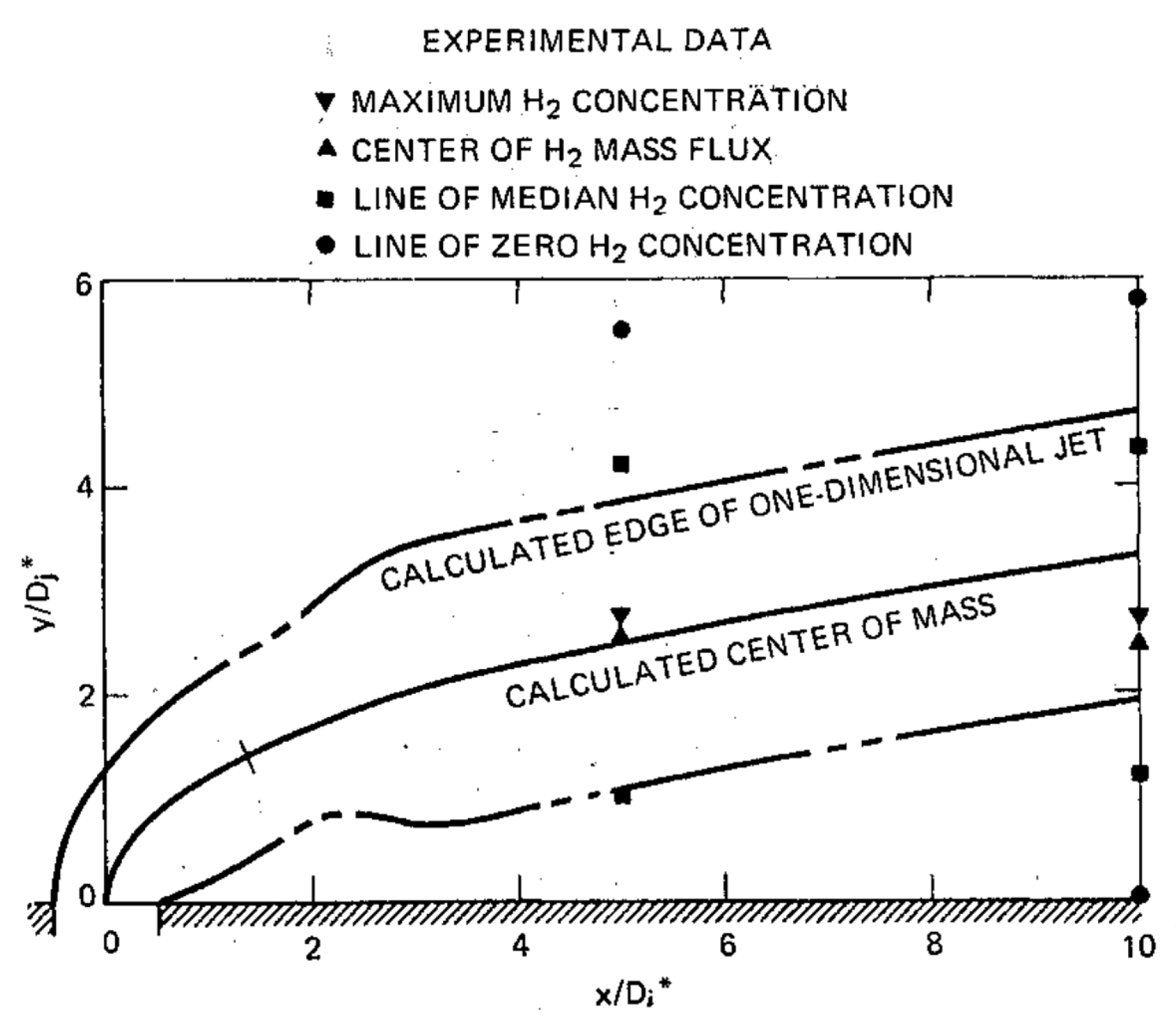
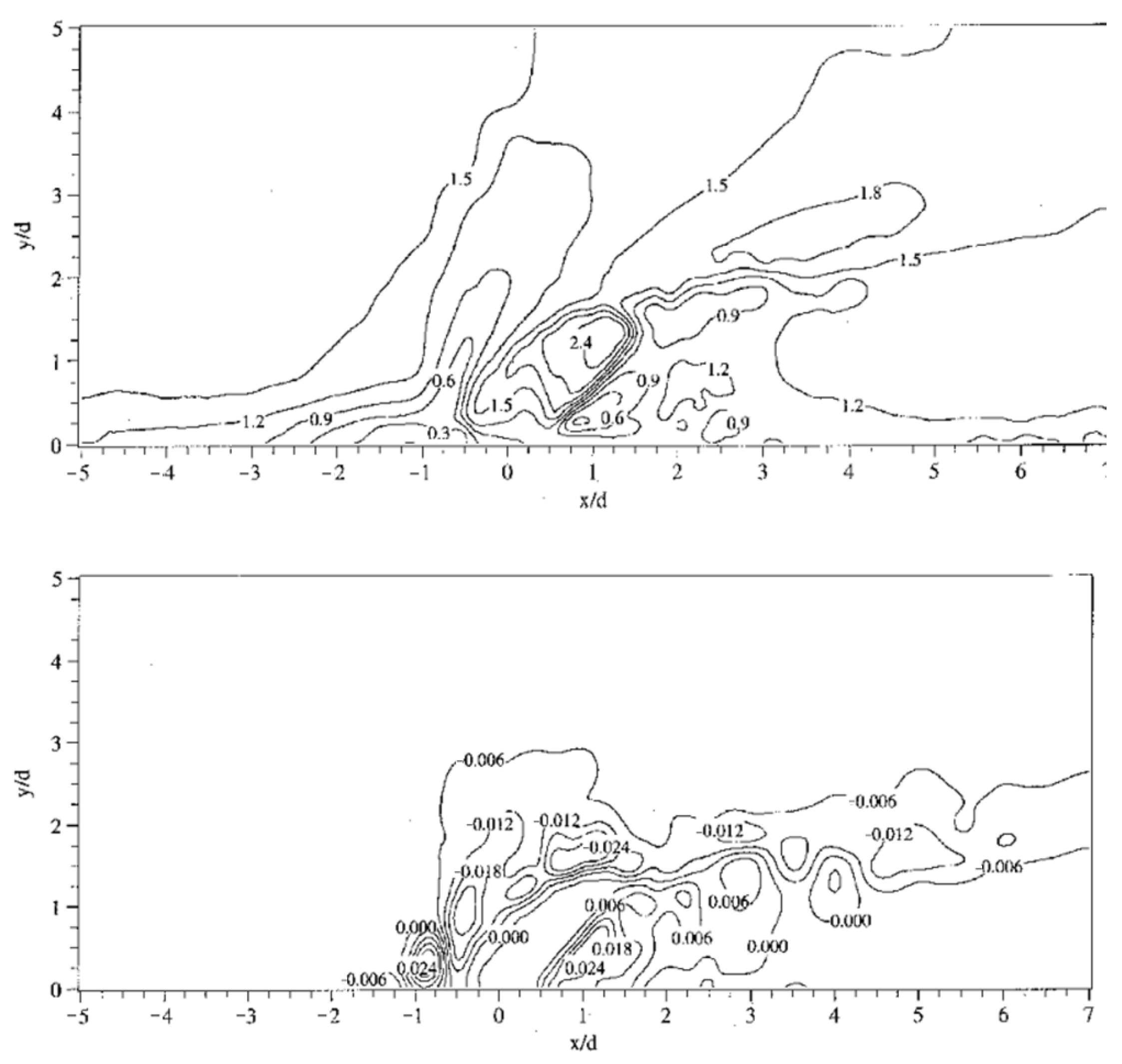
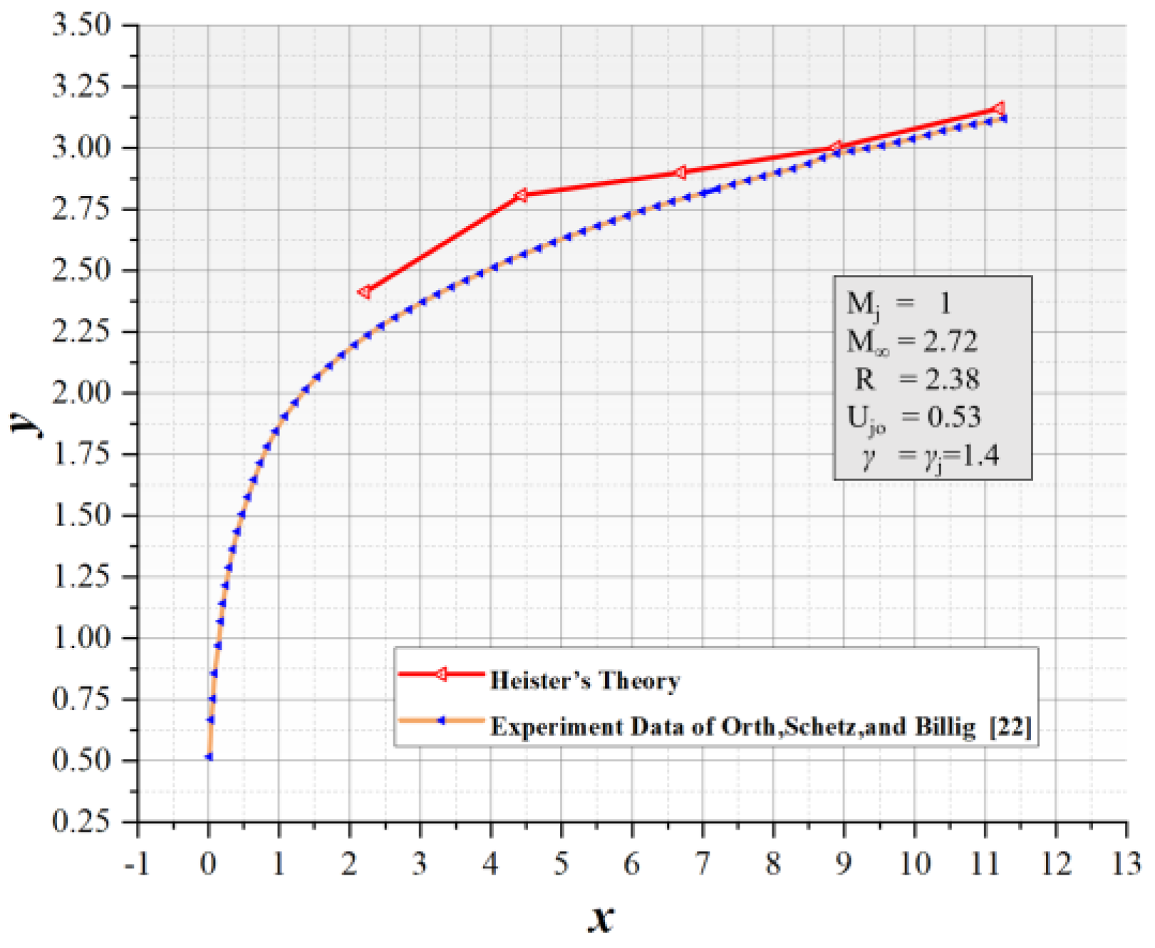
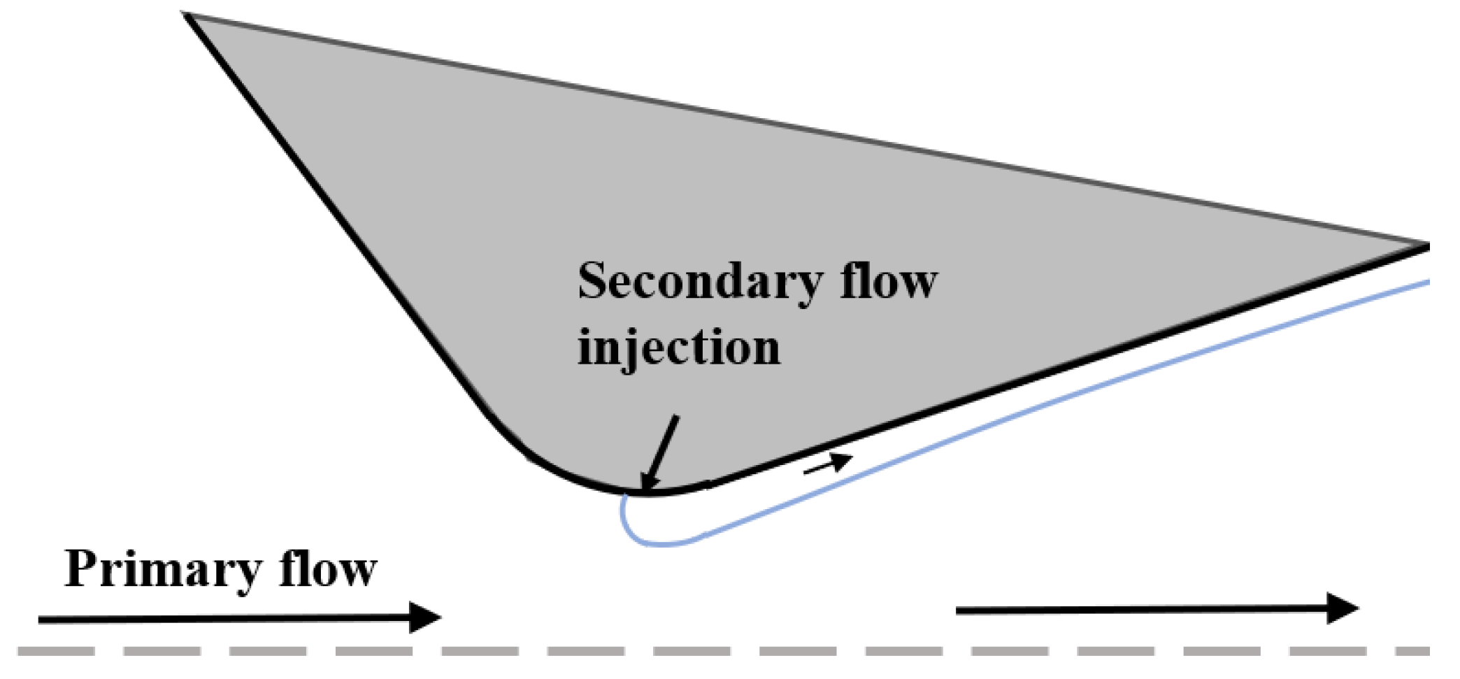

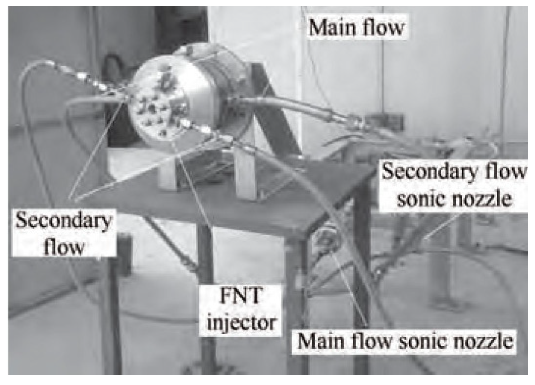
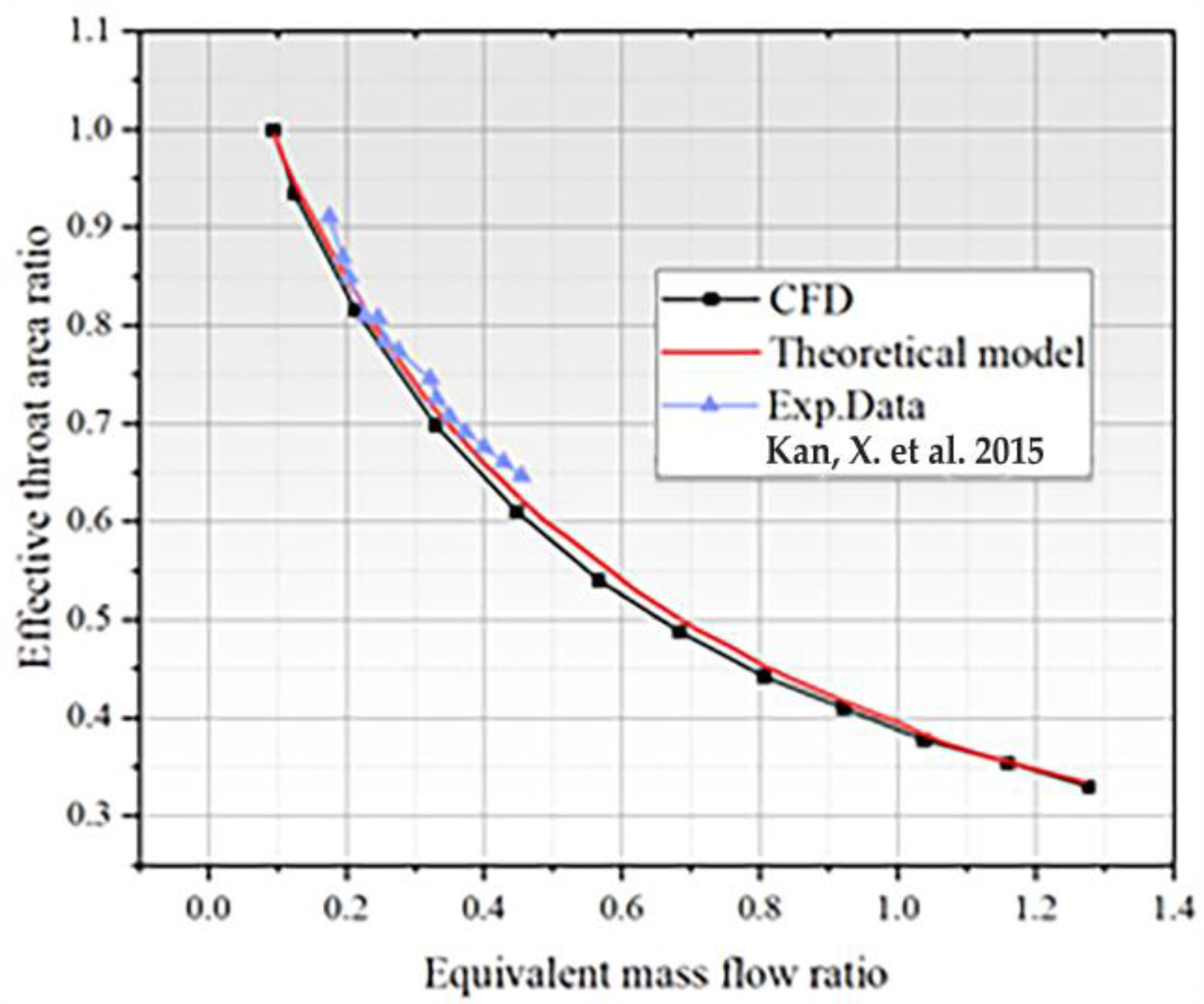

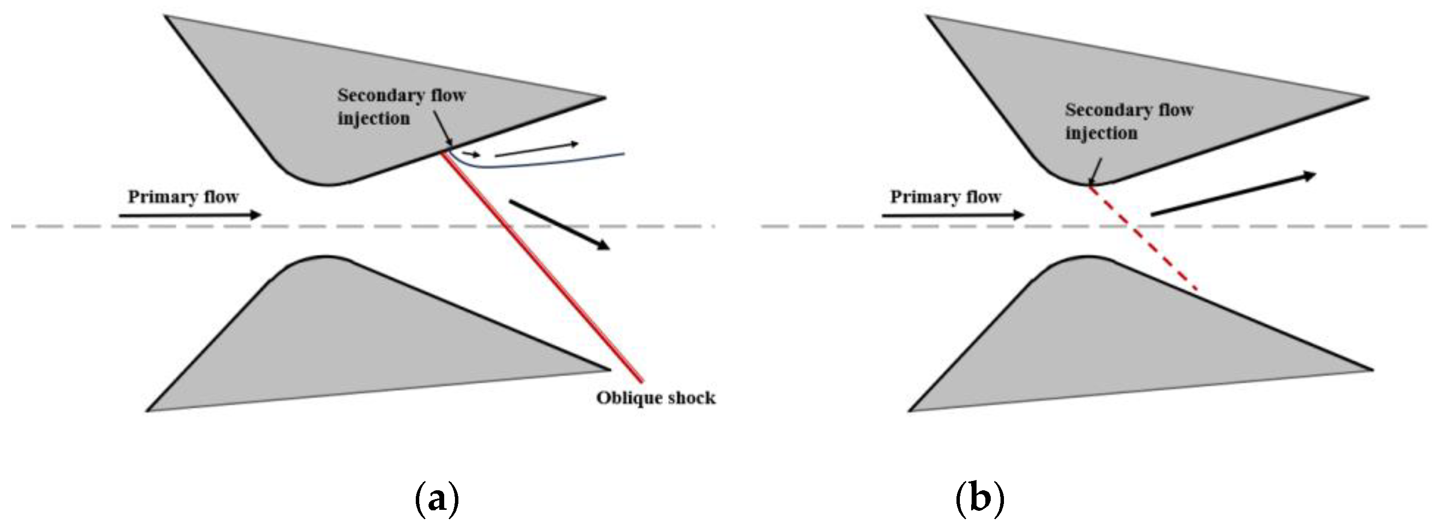


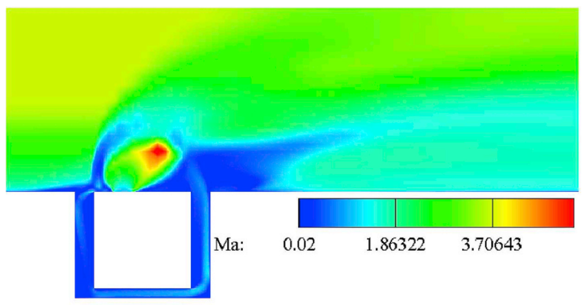

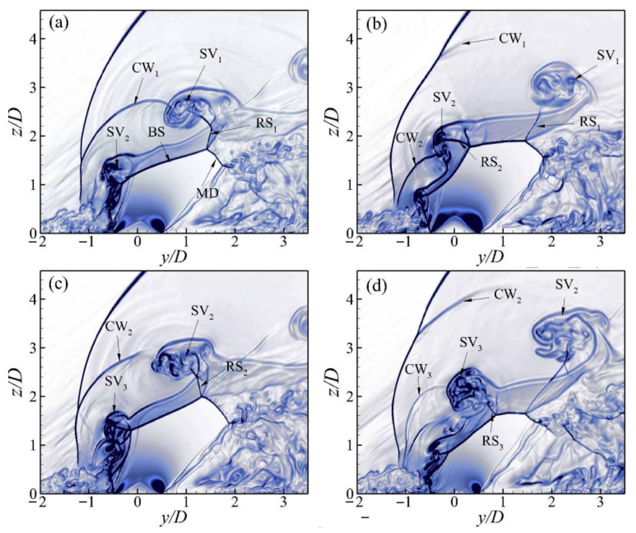
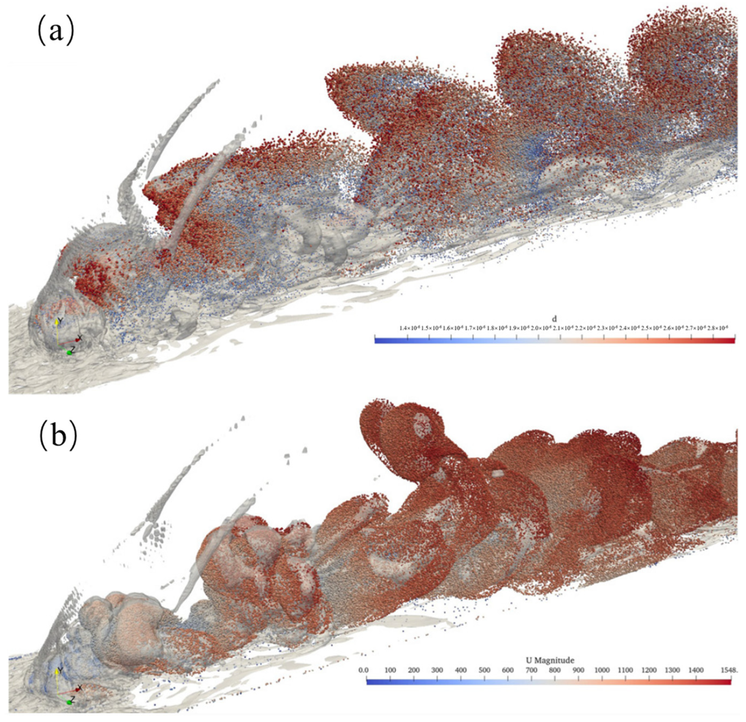
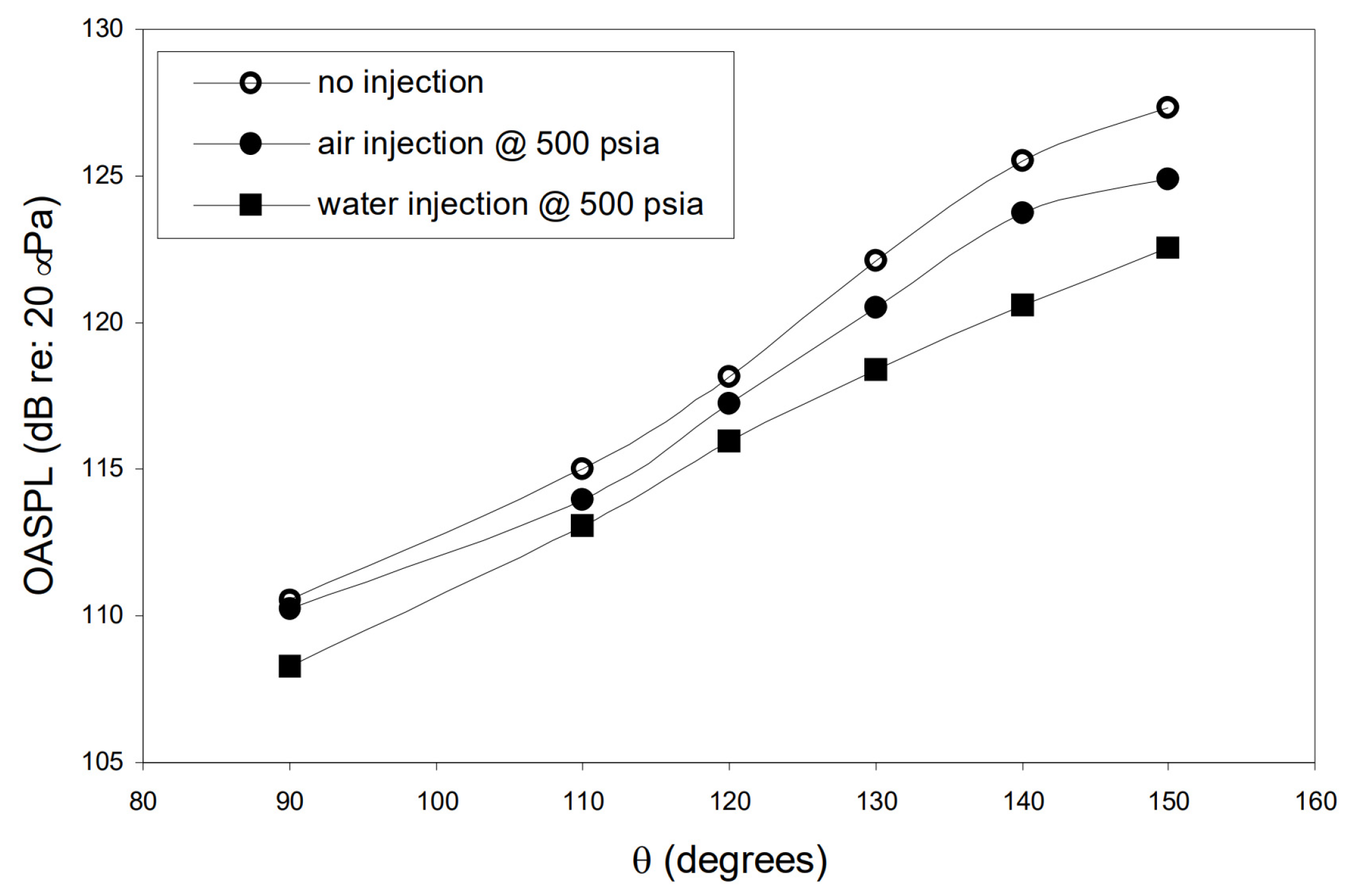
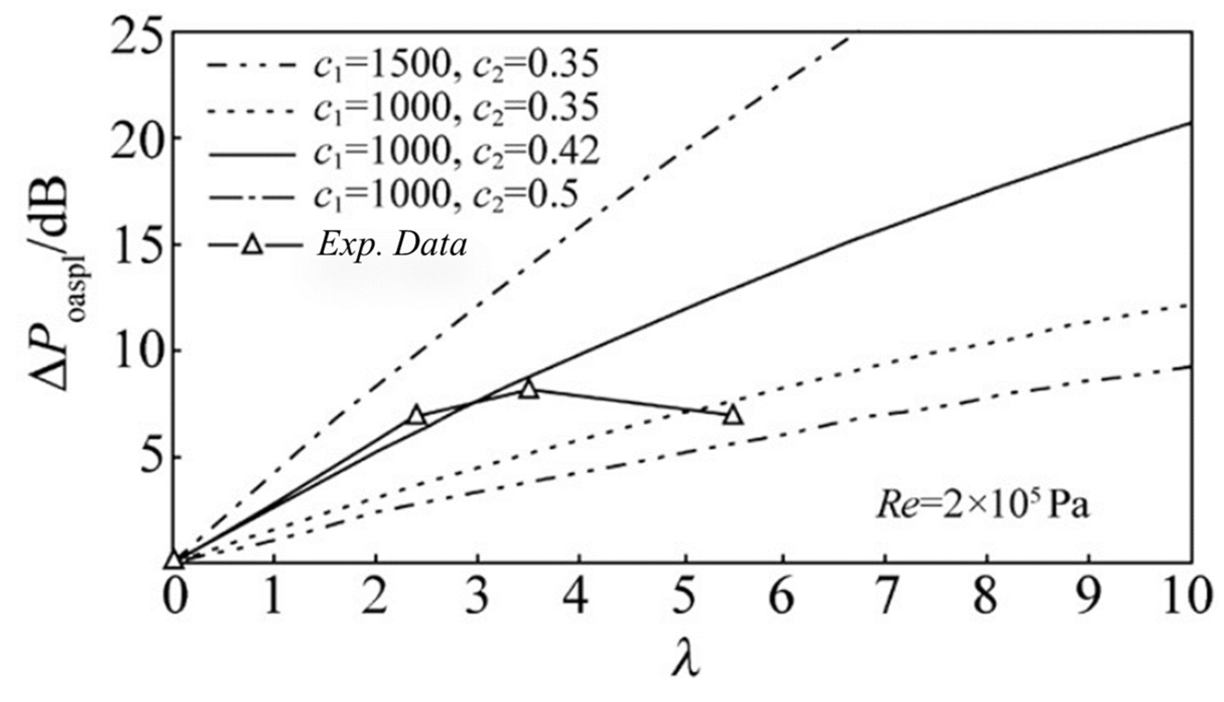
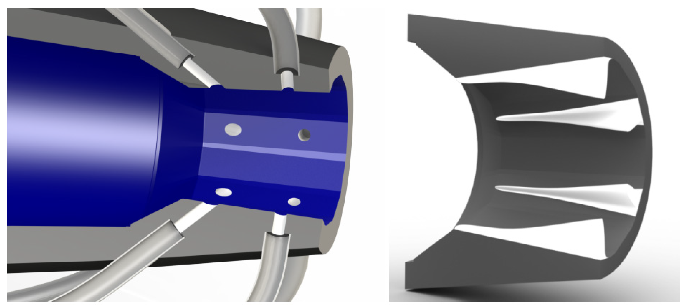
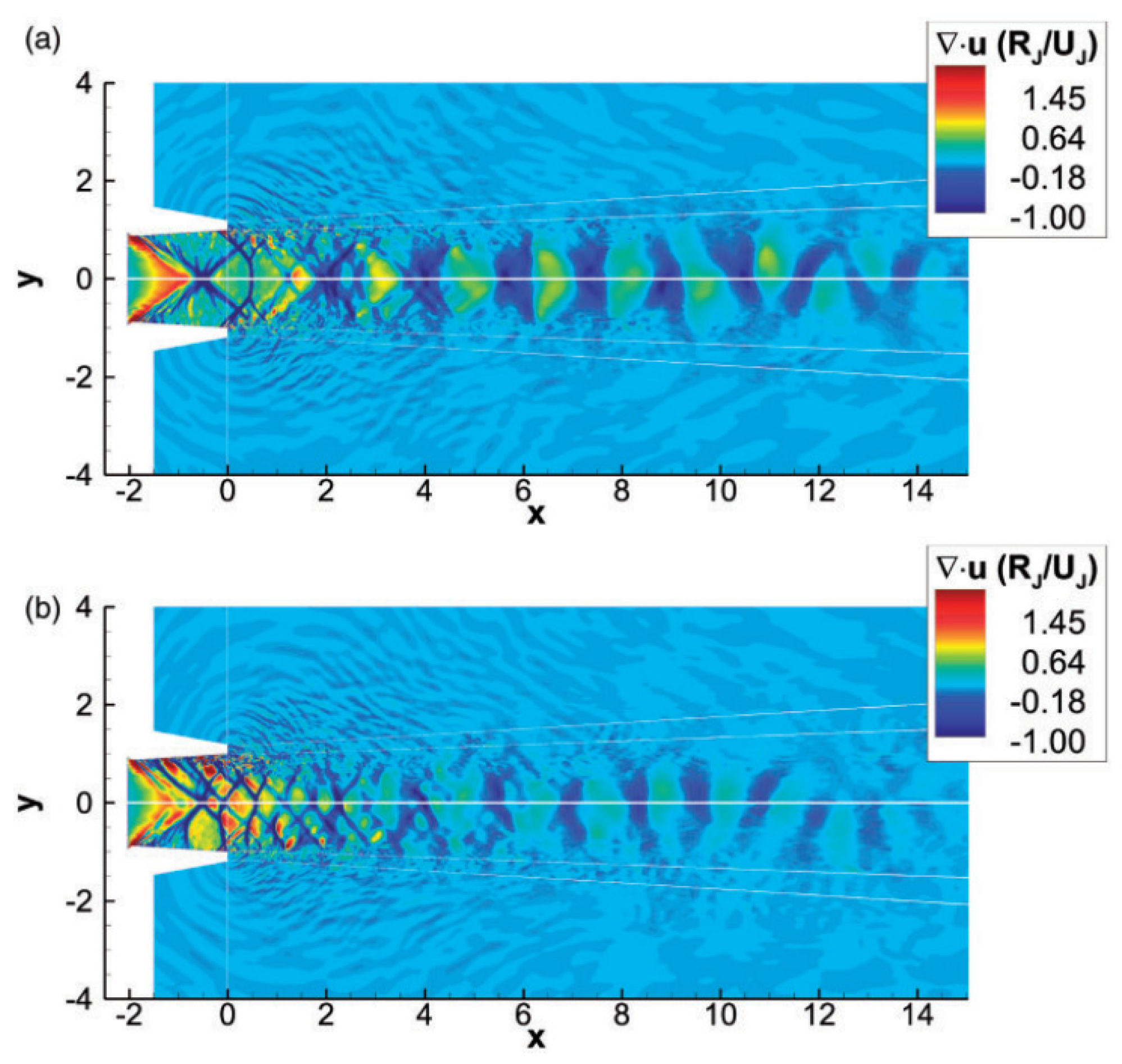

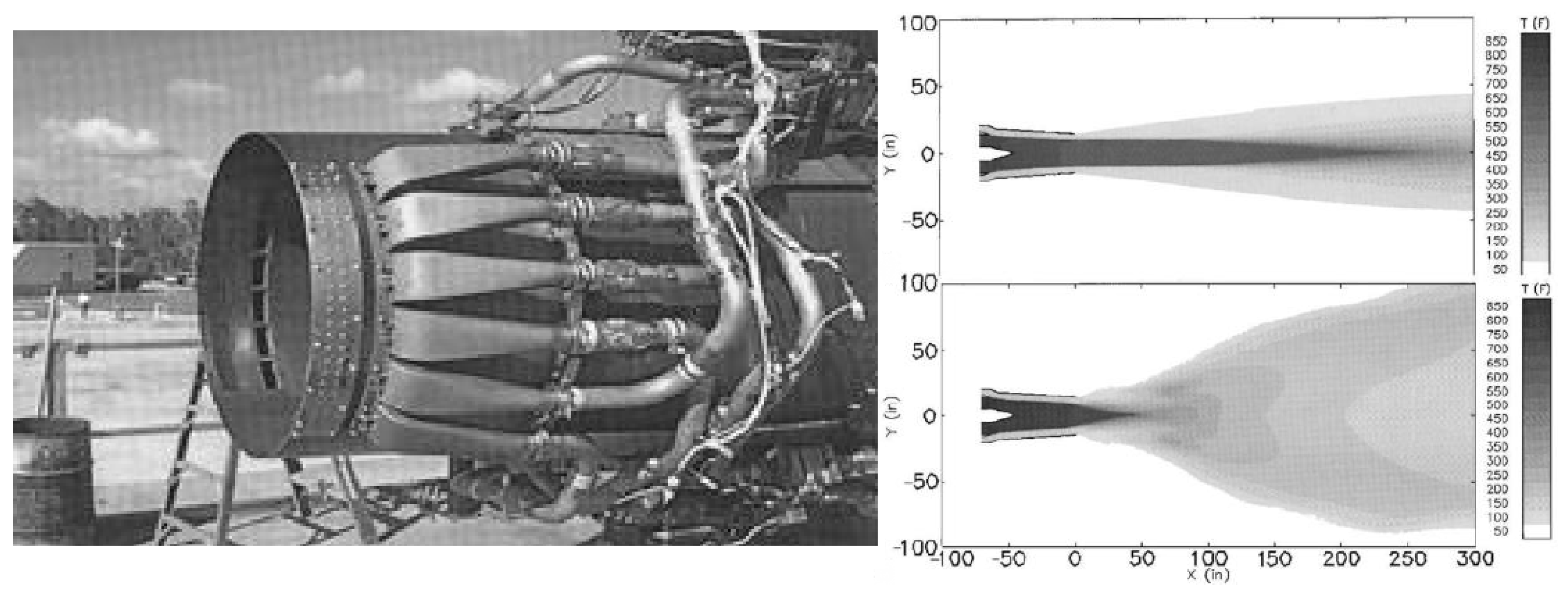
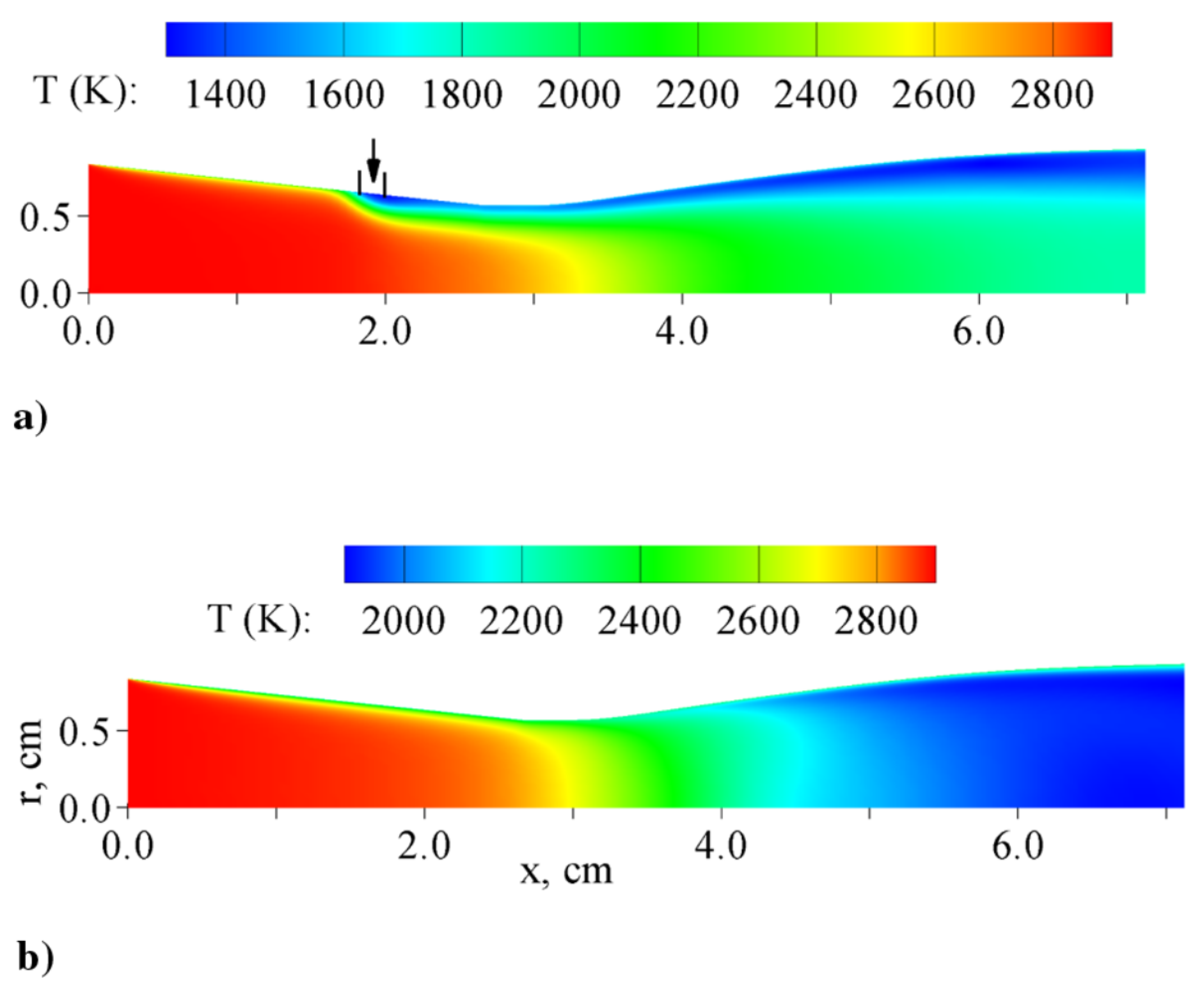
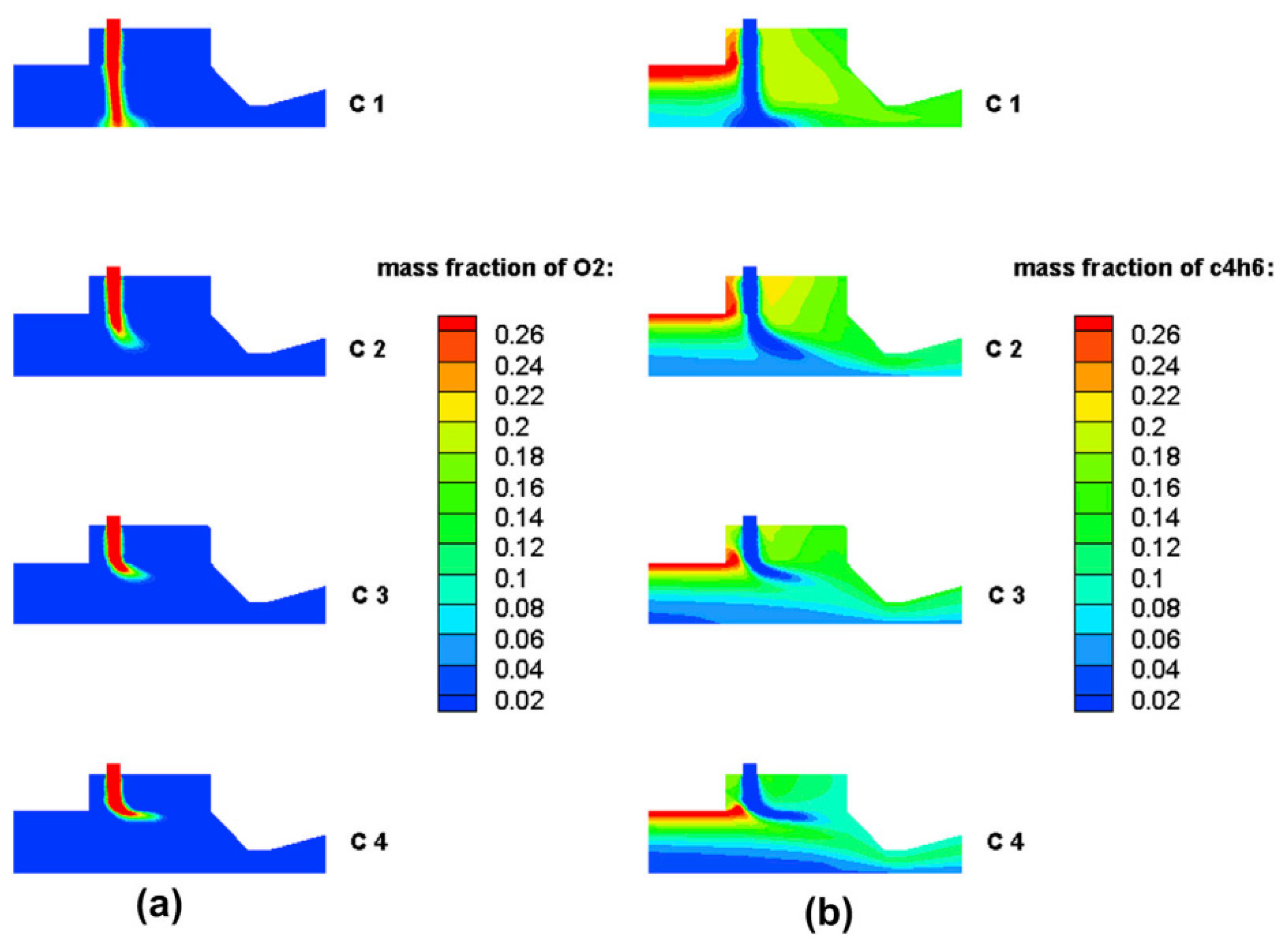
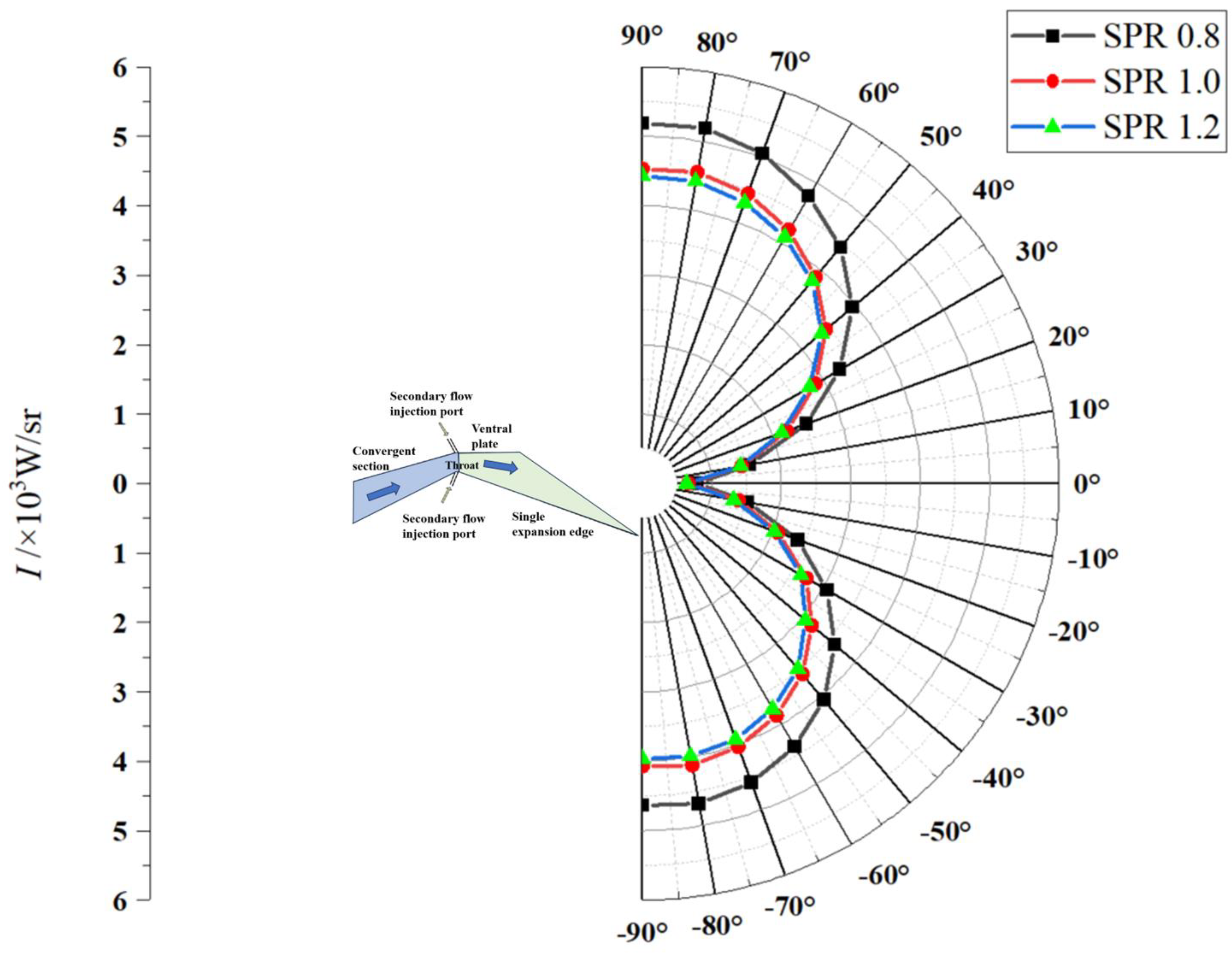
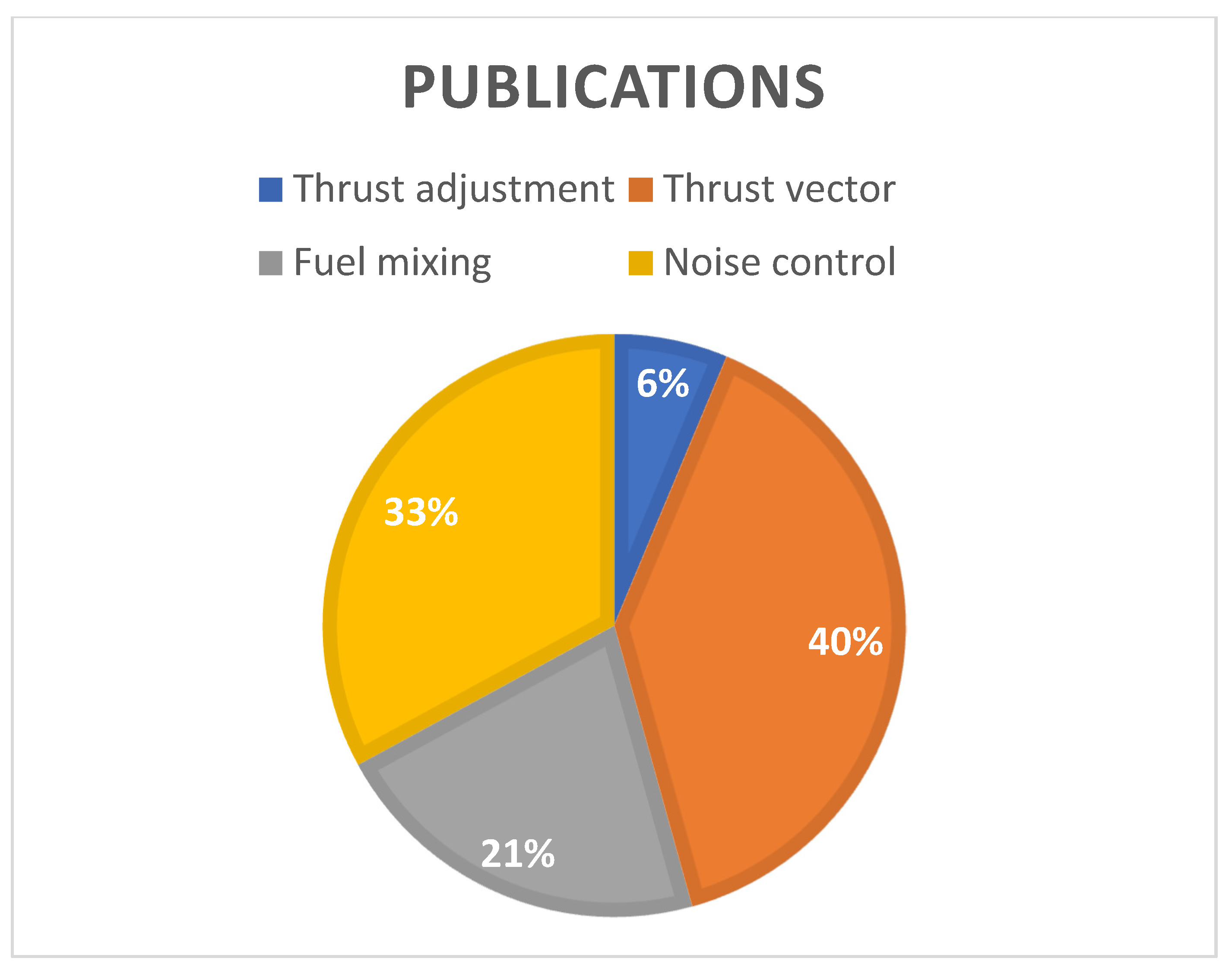
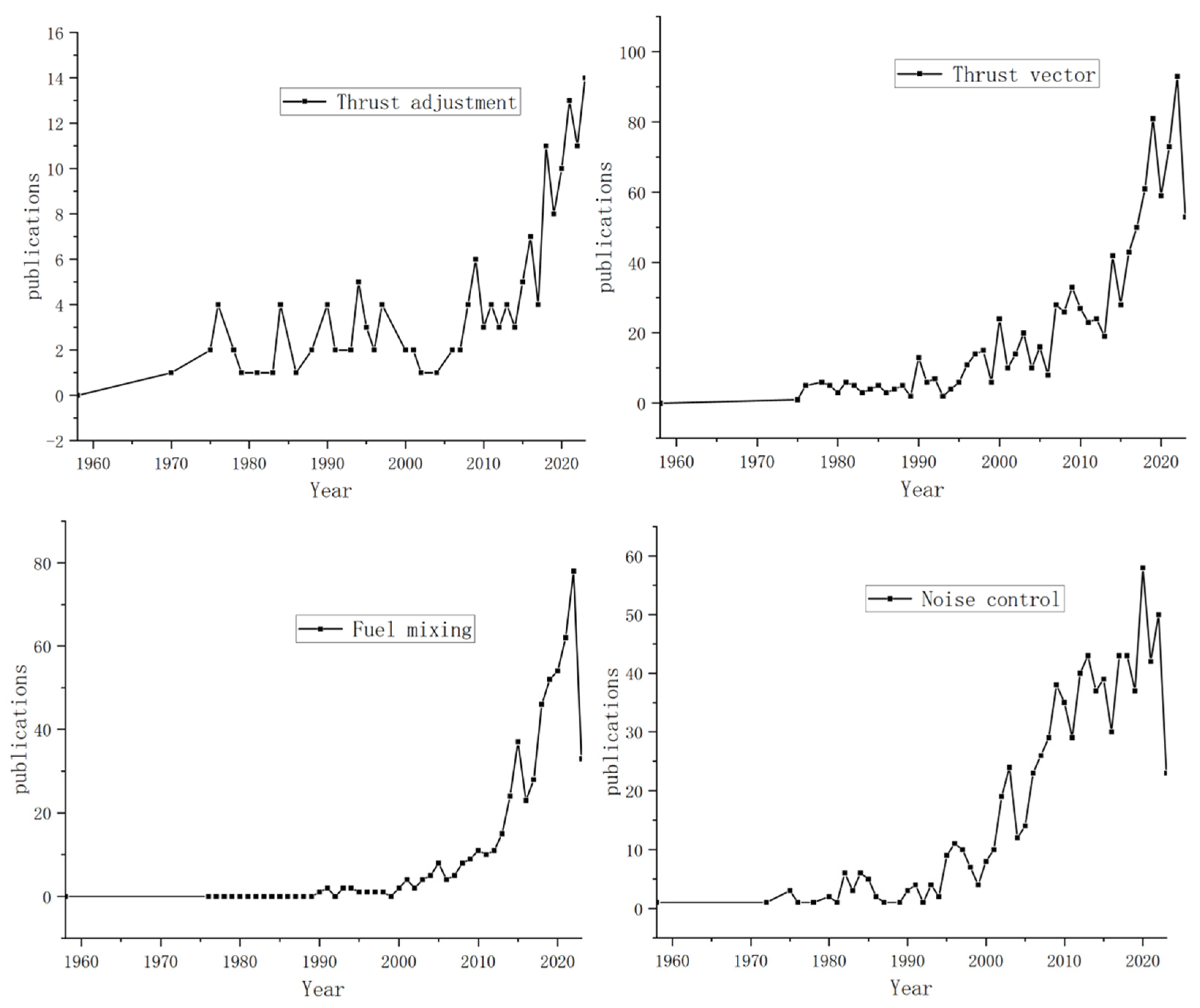
Disclaimer/Publisher’s Note: The statements, opinions and data contained in all publications are solely those of the individual author(s) and contributor(s) and not of MDPI and/or the editor(s). MDPI and/or the editor(s) disclaim responsibility for any injury to people or property resulting from any ideas, methods, instructions or products referred to in the content. |
© 2023 by the authors. Licensee MDPI, Basel, Switzerland. This article is an open access article distributed under the terms and conditions of the Creative Commons Attribution (CC BY) license (https://creativecommons.org/licenses/by/4.0/).