Article

The Influence of Injection Strategy on the Ignition Characteristics of Diesel/Ammonia Premixture

by
Xianli Gao
1,
Qingxing Zhou
2,
Baofu Jia
1,
Zechuan Cui
2,
Hongen Yang
2,
Song Shi
2 and
Jiangping Tian
2,*
1
Zichai Power Co., Ltd., Zibo 255100, China
2
School of Energy and Power Engineering, Dalian University of Technology, Dalian 116024, China
*
Author to whom correspondence should be addressed.
Fluids 2024, 9(10), 224; https://doi.org/10.3390/fluids9100224
Submission received: 9 August 2024 / Revised: 23 September 2024 / Accepted: 25 September 2024 / Published: 26 September 2024
(This article belongs to the Special Issue Advances in Fuel Injection Research for Engines)

Abstract

:
In this paper, based on the optical experimental platform of constant combustion and rapid compression expansion machines, the effects of spray characteristics and injection strategies of diesel in an atmosphere with ammonia on the ignition characteristics of a diesel/ammonia premixture are studied. It is found that in the spray development stage, the liquid-phase penetration distance in ammonia is greater than that in nitrogen. However, the results are opposite in the equilibrium stage. Appropriately increasing the diesel injection pressure can shorten the ignition delay and increase the peak cylinder pressure and projected flame area. The closer the injection time is to TDC, the shorter the ignition delay, and the peak cylinder pressure and heat release rate are lower. The pre-injection strategy can effectively shorten the ignition delay and improve the cylinder pressure and heat release rate.

1. Introduction

For a long time, the heavy use of fossil fuels has caused serious environmental pollution problems. In today’s rapid development of clean energy, there is an urgent need to find a clean source of fuel. Therefore, hydrogen and ammonia, carbon-free fuels, appear in the public view. Hydrogen has the characteristics of low ignition energy, fast burning velocity, a wide flammability limit, etc. [1]. However, a burning velocity that is too fast may lead to abnormal engine combustion [2], and difficult transportation and storage make hydrogen unable to be widely used in power machinery. Ammonia is a carrier of hydrogen. Theoretically, the products of complete combustion are nitrogen and water. It has high hydrogen density, and the volume energy density of ammonia is higher than that of hydrogen itself [3]. Furthermore, ammonia is easier to store and transport than hydrogen; it can be stored at −33 °C [4] at standard atmospheric pressure or as a liquid at room temperature and at a pressure of approximately 1.0 MPa [5]. Table 1 shows the physical and chemical properties of ammonia and other commonly used fuels. Ammonia has a high autoignition temperature, a narrow ignitable range, and a high latent heat of vaporization, which make ammonia difficult to undergo compression ignition in an engine. Gray et al. [6] found that the stable compression ignition of pure ammonia fuel can only be achieved when the compression ratio reaches 35 at an intake temperature of 423 K. Therefore, in the current research, the compression ignition engine is mainly dual-fuel, using highly active fuel (diesel, biodiesel, dimethyl ether, etc.) for ignition, so as to ensure the successful operation of ammonia fuel engine and reduce greenhouse gas emissions. Sun et al. [7] studied the combustion characteristics of ammonia/diesel dual-fuel engines, and found that the peak cylinder pressure and heat release rate gradually decrease with the increase in ammonia energy proportion. Although ammonia has formed uniform premixture at the inlet, ammonia must have the participation of diesel to achieve combustion. Moreover, the ammonia energy proportion mainly affects the combustion duration.
Injection strategy for igniting diesel is an important factor that influences the effects of ammonia premixture combustion. Yousefi et al. [8] carried out an ammonia/diesel dual-fuel engine experiment and numerical simulation on a single cylinder diesel engine. The results showed that the method of diesel ignition can ensure the stable combustion of ammonia. In the case of a fixed diesel injection moment, increasing ammonia energy fraction can increase N2O emissions, which offsets the benefits of reducing CO2 emissions, resulting in higher greenhouse gas emissions than those exhausted by a pure diesel mode. Yoichi Niki et al. [9] studied the effects of multiple diesel injection on the emission characteristics of ammonia doping in the air intake of a diesel engine, and the results show that multiple diesel injection is one of the effective measures to reduce N2O and NH3 emissions of ammonia/diesel dual-fuel engines.
In summary, the currently available literature on diesel/ammonia dual-fuel engines primarily focuses on computational fluid dynamics (CFD) calculations of the working process or on engine testing. There are relatively few visualization studies related to spray, mixture formation, and combustion processes. Due to the differences in the physical properties of ammonia, particularly in terms of density and thermal conductivity, the atomization and evaporation characteristics of the pilot diesel spray may change when injected into an ambient mixture containing ammonia. This is crucial for achieving high-precision CFD simulations of diesel pilot spray and the subsequent combustion processes in diesel/ammonia dual-fuel engines. This paper combines experimental and CFD calculation methods. First, based on the constant-volume-combustion optical experimental platform, the experiment on the spray characteristics of diesel in an ammonia atmosphere is carried out. Then, based on the rapid compression expansion machine (RCEM) optical experimental platform, the effects of ignition diesel injection pressure, injection timing on diesel ignition characteristics, and ammonia combustion characteristics are studied. Finally, the spray of diesel in an ammonia atmosphere and the combustion cylinder pressure of RCEM are calibrated, and the influence of a pre-injection diesel strategy on combustion effects is calculated.

2. Materials and Methods

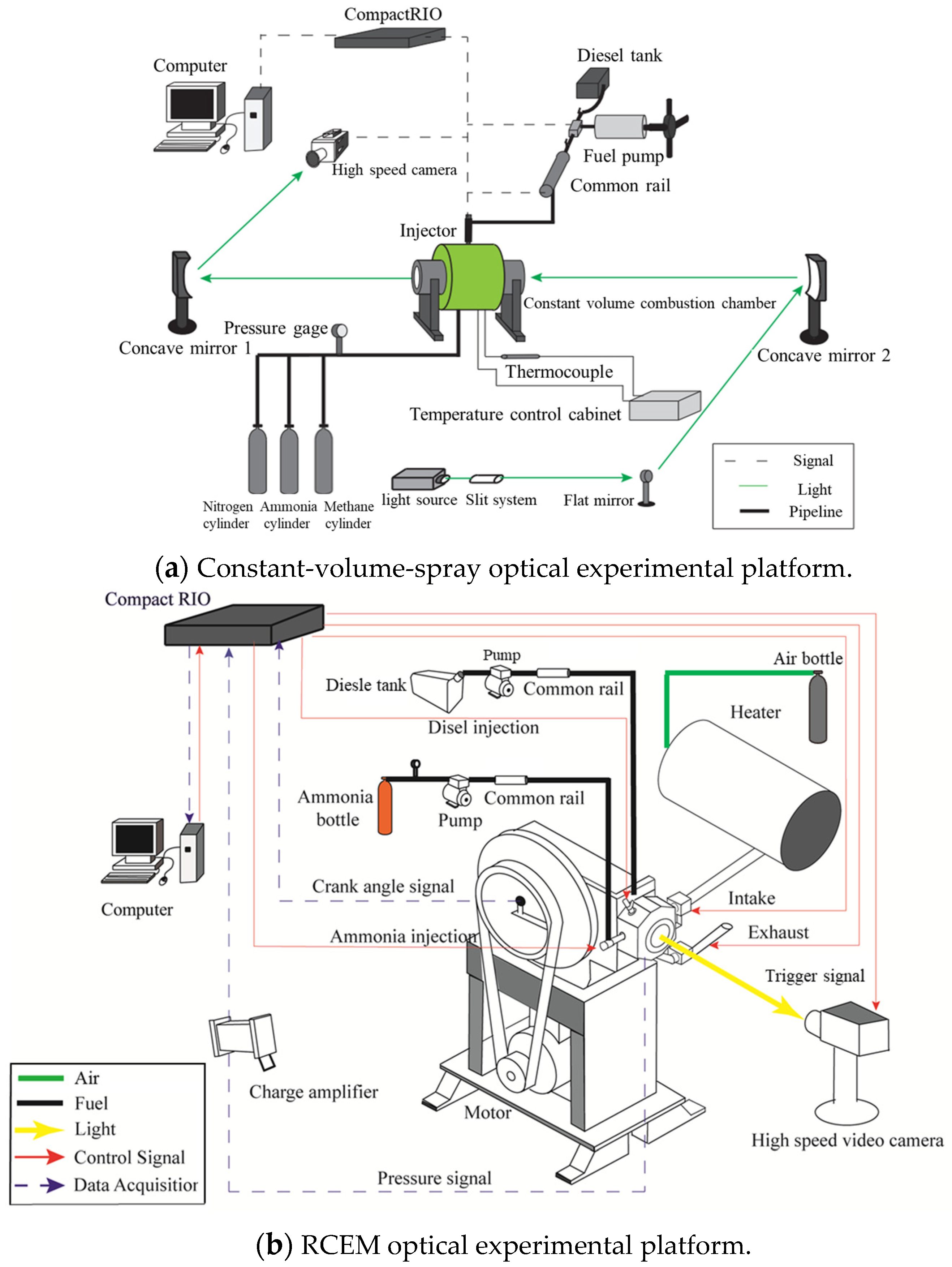
2.1. Experimental Setup

The experimental setup consists of two parts. As shown in Figure 1a, a constant-volume-spray optical experimental platform is used to determine spray characteristics of diesel in an ammonia/air atmosphere. As shown in Figure 1b, the RCEM optical experiment platform consists of a rapid compression expansion machine, heating system, intake and exhaust system, control system, and optical path system. The rapid compression expansion machine is converted from a diesel engine and the original cylinder block is retained. The rotational speed is 270 r/min, the cylinder diameter is 135 mm, the stroke is 145 mm, and the compression ratio is 7.66. The RCEM retains the original cylinder block and crank linkage system. The combustion chamber volume is increased and uses a visual combustion test section instead of a cylinder head, which is driven by an electric motor in reverse drag. In order to ensure that the rapid compression machine reaches enough temperature and pressure, the strategy of intake heating and pressurization is adopted. Figure 1c is a schematic diagram of the modified combustion section. A K-type thermocouple is used to detect the cylinder temperature, and a Kistler6052C pressure sensor and Kistler5018A charge amplifier (produce by Kistler company, Winterthur, Switzerland) are used to collect the cylinder pressure. The window is embedded with sapphire glass, which can withstand the maximum pressure of 20 MPa and reach a visual range of 90 mm. Liquid ammonia is injected into the combustion test terminal at the intake stage, forming a premixture with air, into which diesel is injected and subsequently ignites the ammonia/air premixture before reaching the TDC (top dead center).

2.2. Experimental and Calculation Conditions

Researching the spray characteristics of diesel in an ammonia atmosphere is crucial since a relatively uniform premixture is formed in the cylinder before diesel injection. Subsequently, the influence of the injection strategy on the ignition characteristics of ammonia premixture ignited by diesel is studied by changing the injection pressure, injection timing, and pre-injection strategy. The experimental conditions for the spray are shown in Table 2, and the experimental and calculation conditions for the combustion are shown in Table 3.

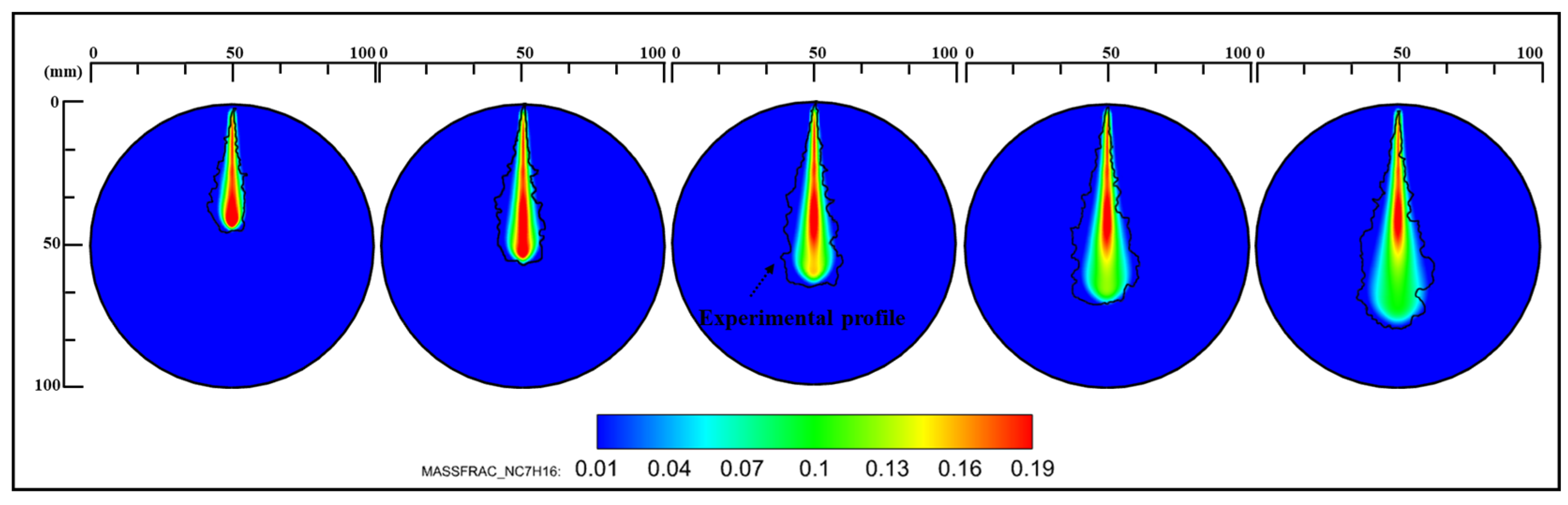
2.3. Establishment and Calibration of the CFD Model

Based on the RCEM optical experimental platform and the CONVERGE 3.0.1 engine simulation software, this paper establishes a corresponding CFD model, calibrates the spray and combustion results, and studies the injection strategy of pre-injected diesel. Figure 2 is the spray penetration distance images of diesel in ammonia/nitrogen and pure nitrogen atmospheres. In the figure, ASOI stands for “after the start of diesel injection”. In the liquid spray development stage, compared with the pure nitrogen atmosphere, the addition of ammonia reduces the density of environmental media. Therefore, the liquid-phase penetration distance of diesel in the ammonia/nitrogen atmosphere is greater. As the diesel spray reaches the equilibrium state, the liquid-phase penetration distance of diesel in the ammonia/nitrogen atmosphere is lower than that in the pure nitrogen atmosphere. That is because the addition of ammonia will increase the speed of spray evaporation. Therefore, in the meteorological penetration distance, the penetration distance of diesel in the ammonia/nitrogen atmosphere is higher than that in the pure nitrogen atmosphere.
The main models of the CFD calculation section are shown in Table 4. Figure 3 shows the calibration of the gas–liquid-phase penetration distance in the case 2 condition in Table 2. It can be seen that the calculated penetration distance achieves a high level of compliance with the experimental results. Figure 4 shows the profile of diesel spray under this condition. The black solid line shows the spray outline under the shadow method. According to the research by Li et al. [10], both the LES and RNG k-ε turbulence model can better describe the spray form, and the LES model can better describe the turbulence of the spray boundary. However, due to the huge amount of calculation, this paper adopts the RNG k-ε turbulence model.
Figure 5 shows the cylinder pressure calibration curve of this study, corresponding to the case 4 condition. Among them, diesel starts to inject at −9 deg, using a 4 mm base grid, a 2-level adaptive encryption, and a 3-level encryption for the nozzle. Figure 6 is the flame picture in the experiment and calculation of the same moment. The flame burns for a very short time, so the thermocouple cannot measure the temperature in a very short time. Therefore, we use the temperature field to approximately replace the flame. It can be seen that the combustion speed of the ammonia premixture is slow. The flame does not appear until the diesel injection is at around 9.8 deg. At 35.1 deg after injection, the flame occupies about two-thirds of the window. Comparing the CFD results with the experimental results, it can be seen that the photos are in good agreement with the calculated results, so the model settings will be applied to the subsequent calculations.

3. Results and Discussion

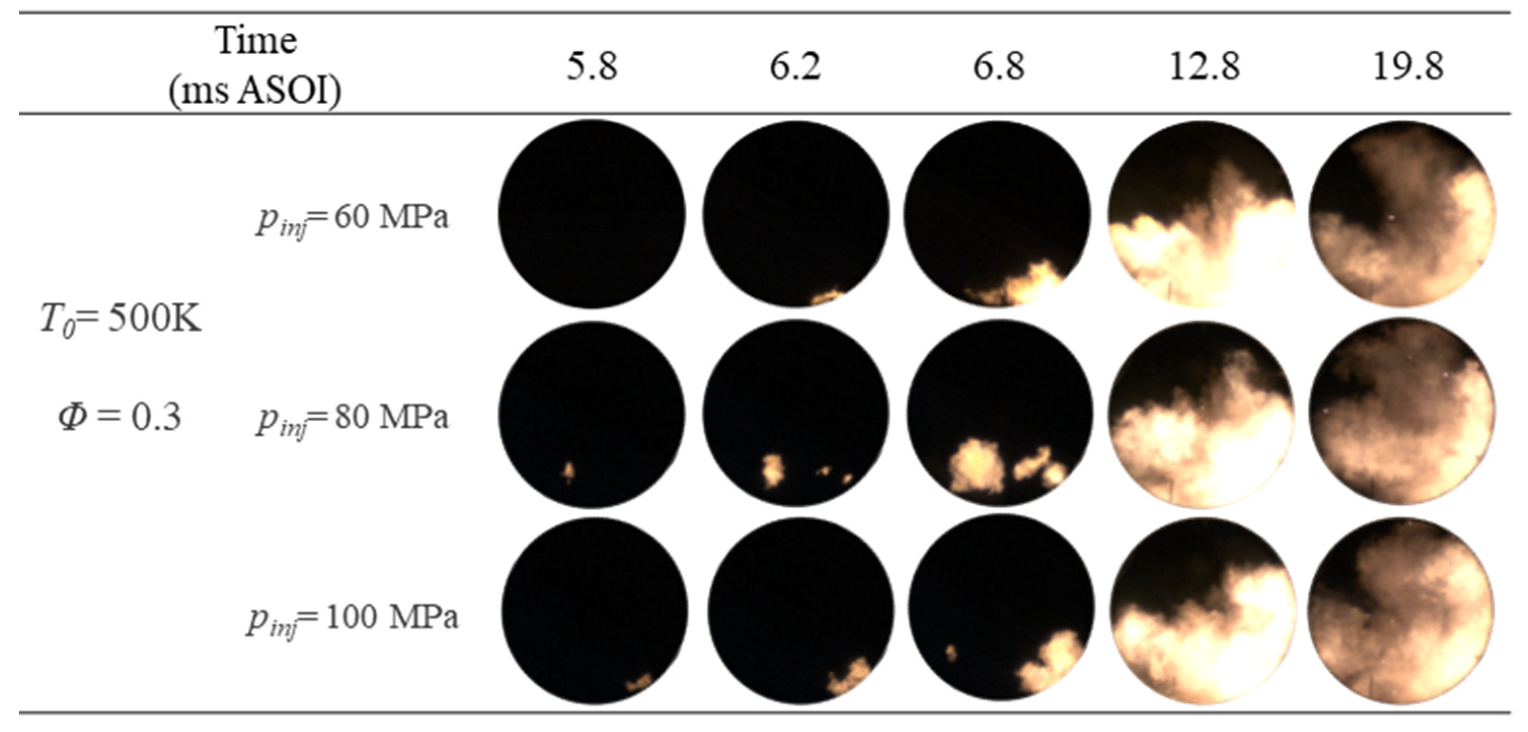
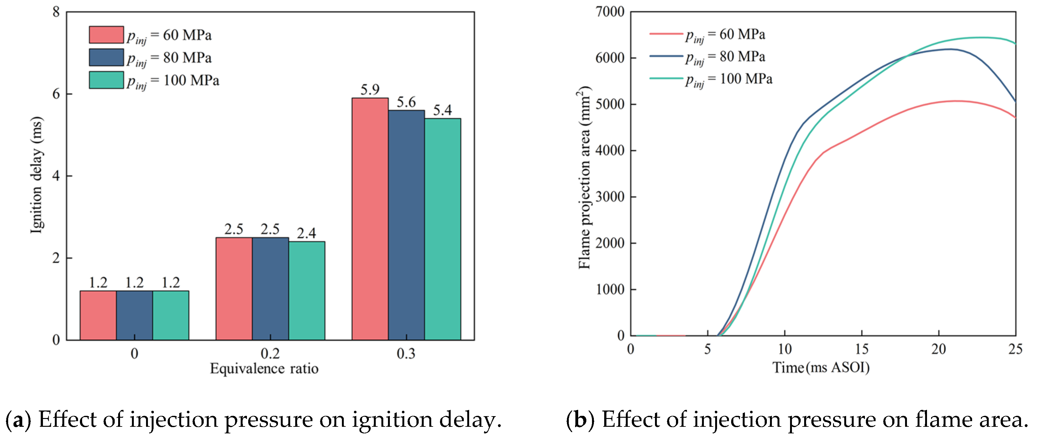
3.1. Effects of Injection Pressure of Pilot Diesel

To determine the effects of injection pressure on the combustion process of the ammonia/diesel premixture, the experimental conditions used in this section are case 1–case 6. As injection pressure is positively correlated with diesel injection volume, the injection pulse width of diesel is adjusted to maintain a constant diesel injection volume during this experiment, allowing for a separate analysis of the experimental variable injection pressure.
Figure 7 shows an image of the flame development during the process of diesel igniting the ammonia premixture at different injection pressures (pinj). The pilot diesel flame starts to fire near 5.8 ms ASOI, the initial fire position at pinj = 80 MPa is close to the center of the cylinder, and the initial fire at pinj = 100 MPa is close to the wall. The moment of the flame’s appearance at pinj = 60 MPa is the latest, and the ignition timing at pinj = 80 MPa is similar to that at pinj = 100 MPa, which indicates that increasing the injection pressure helps to ignite the atomization of the diesel spray and mix it with the air in the environment earlier to reach the ignition conditions. At 6.2 ms ASOI, three masses of flame can be clearly observed in the pinj = 80 MPa image, which intuitively reflects that there are more initial ignition points, and the ignition position is closer to the center of the cylinder compared to that under other injection pressures. The ignition stage of pinj = 60 MPa and 100 MPa is mainly one mass of flame and close to the wall, which hinders the development of the flame to some extent. At 6.8 ms ASOI, the phenomenon is more obvious. The multiple flames of pinj = 80 MPa begin to develop and gradually grow closer. Although there is little difference between the flame areas of the three in the image, in general, the multiple flames make the ignition stage of pinj = 80 MPa start with a wider flame area. As the flame of pinj = 60 MPa and 100 MPa develops at the wall, the heat exchange between the flame and the wall increases and the development of the flame slows down.
Figure 8a shows the influence of different injection pressures on the ignition delay. In this paper, the ignition delay is defined as from the start of fuel injection (calculated as the main injection time for the pre-injection strategy) to the end of the first photo of the flame. As can be seen from the image, the ignition pressure has little effect on the ignition delay under the diesel mode and low equivalence ratio. At Φ = 0.3, the increase in injection pressure shortens the ignition delay. The ignition delay at pinj = 60 MPa, 80 MPa, and 100 MPa is, respectively, 5.9 ms, 5.6 ms, and 5.4 ms, and the ignition delay is, respectively, shortened by 5.1% and 3.6% after increasing the injection pressure. This is mainly because the injection pressure increases and the kinetic energy of diesel droplets is higher, which accelerates the mixing of diesel spray and air, and therefore, the ignition conditions are reached earlier. This pattern can also be better observed from the image of the flame propagation process.
Figure 8b shows the influence of different injection pressures on the projected area of the flame. As can be seen from the image, the flame at pinj = 60 MPa appears the latest, and there is little difference in the appearance time between the projected flame area of pinj = 80 MPa and 100 MPa. In the early stage of flame development, the projected flame area at pinj = 80 MPa is larger, its growth rate is comparable to that at pinj = 100 MPa, and the flame at pinj = 60 MPa shows the slowest growth. After the projected flame area increases to a certain degree, the projected flame area at pinj = 100 MPa increases faster than that at pinj = 80 MPa, probably because the distribution of diesel and ammonia premixture is more uniform under the high injection pressure. From the perspective of the overall law, increasing the injection pressure has little impact on the growth rate of the projected flame area in the early pilot diesel stage, but it will increase the growth rate of the ammonia flame area in the later stage, and the maximum flame area is positively related with the injection pressure.
The HRR was calculated from the pressure by Formula (1) as follows. In the formula, γ is the adiabatic coefficient of the working medium in the cylinder, whose value was chosen as 1.33 in this paper; p is the pressure in the cylinder; V is the cylinder volume; and φ is the crank angle at the same moment as V:
H R R = γ 1 γ p · d V d φ + 1 1 γ V · d p d φ
Figure 9 is the cylinder pressure and heat release rate curve. When Φ = 0.2, the highest combustion pressure changes slightly as the injection pressure increases, and the peak exothermic rate increases from 134.03 J/° CA to 172.18 J/° CA, increasing by 28.5%, and the combustion phase also advances by 0.4° CA. This is because the increase in the injection pressure adds to the kinetic energy of ignition diesel droplets, which accelerates the mixing of the diesel spray with ammonia and air; the evaporation rate of pilot diesel promotes the atomization of diesel, forms a large amount of combustible mixture earlier, and contributes to the combustion process. When Φ = 0.3, the injection pressure increases from pinj = 60 MPa to pinj = 100 MPa, the highest combustion pressure increases by 7.1%, and the appearance time is delayed by 3.4° CA. As can be seen from the heat release rate curve, the peak release rate at pinj = 80 MPa is 195.7 J/° CA, which is the highest, followed by pinj = 60 MPa and 100 MPa. Therefore, the peak heat release rate under high injection pressure is reduced, which is 16% lower than that of pinj = 80 MPa, and the peak heat release rate appears 0.6° CA later than that of pinj = 80 MPa. The peak heat release rate at pinj = 60 MPa is lower than that of pinj = 80 Mpa due to the better atomization effect of the pilot diesel after increasing the injection pressure, which is closer to the premixed heat release. As the injection pressure continues to increase to pinj = 100 MPa, the high injection pressure increases the initial kinetic energy of the diesel spray, adds the turbulence disturbance in the cylinder, and accelerates the mixing process. The droplet size of high injection pressure is smaller, forming a better crushing diesel spray with a faster evaporation rate. However, as the ignition delay is longer under the high equivalence ratio, the distribution of diesel spray is excessively dispersed. While the spray crushing atomization at pinj = 60 MPa is not as good as pinj = 100 MPa, the fuel distribution is avoided from being too dispersed to some extent.

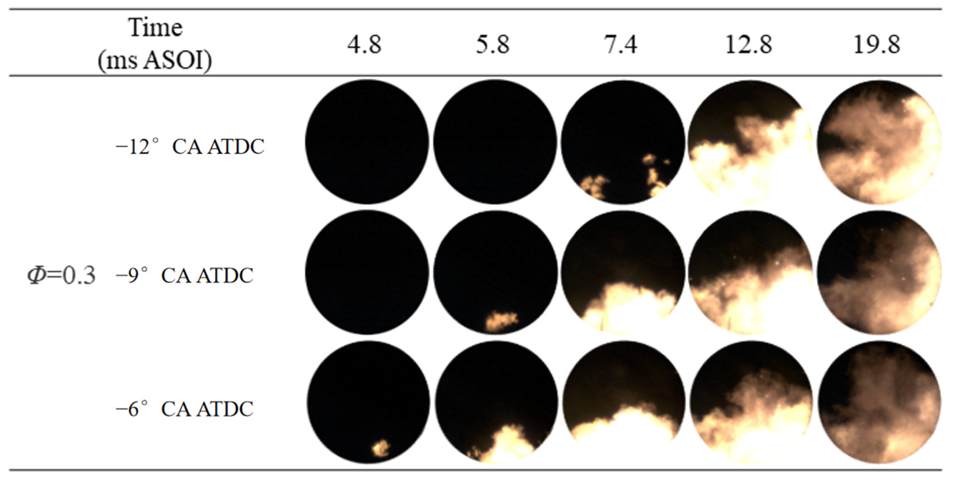
3.2. Effects of Injection Timing of Pilot Diesel

In order to determine the effect of injection timing on the combustion process of diesel ignition ammonia premixture, the experimental condition used in this section is case 7–case 10. Figure 10 shows the combustion image of the diesel ignition ammonia premixture process at Φ = 0.3 under different injection timings. As can be seen from the image, the diesel injection time of τ = −12° CA ATDC is the earliest, but it does not catch fire first. The first diesel flame appears at τ = −6° CA ATDC, and that is because τ = −6° CA ATDC is the closest to TDC, whereby the higher the temperature and pressure, the more appropriate the diesel spray concentration and the earlier the combustion conditions are reached. The starting flame distribution of τ = −12° CA ATDC is wide, which makes multiple flames start to burn at the same time. The combustion position has a certain distance from the wall, and this is because injection time at τ = −12° CA ATDC is earlier, diesel and air experience a thorough mixture before the combustion, and the combustible premixture is distributed to more locations before ignition. Therefore, a multipoint combustion is presented when it is on fire. At 12.8 ms ASOI, the flame forms of different injection timings are not much different. The ammonia flame begins to expand outward on the surface of the diesel flame. At 19.8 ms ASOI, the ammonia flame almost covers the window.
Figure 11a shows the influence law of different injection timings on the ignition delay. At Φ = 0.2, the ignition delay of τ = −12° CA ATDC and τ = −6° CA ATDC is, respectively, 3.2 ms and 2.1 ms, and the advancement of the injection timing leads to a 52.3% extension of the ignition delay; at Φ = 0.3, the ignition delay of τ = −12° CA ATDC and τ = −6° CA ATDC is, respectively, 6.2 ms and 4.4 ms, extending the ignition delay by 41%. This is because when the injection timing is closer to TDC, the reaction is promoted by the higher temperature and pressure of TDC. Figure 11b shows the influence law of different injection timings on the projected flame area. As can be seen from the image, the projected flame area of τ = −6° CA ATDC begins to develop first, and the projected flame area in the early stage is greater than those of τ = −9° CA ATDC and τ = −12° CA ATDC. This is because τ = −6° CA ATDC is closer to TDC, and the high temperature and pressure in the early stage promotes the combustion process. After reaching a certain moment, the projected flame area at τ = −12° CA ATDC exceeds other injection timings, and the projected flame area grows faster. This is mainly because the advancement of injection timing leads to the prolonged ignition delay. A longer ignition delay makes the pilot diesel and ammonia premixture fully mixed, which promotes the combustion process of ammonia premixture later.
Figure 12 is the cylinder pressure and heat release rate curve. With the advancement of the injection timing, the peak combustion pressure increases, the combustion phase is advanced, and the peak heat release rate also increases. This is because the advancement of the pilot diesel injection timing enables the diesel to mix with the air in the cylinder for a longer time. When the piston moves to TDC, due to the long stagnation period of the ammonia premixture, the earlier the moment of diesel injection, the longer the stage of diesel forming the premixture in the cylinder and the better the homogeneity of mixing. Therefore, the peak heat release rate at τ = −12° CA ATDC is the highest. It is worth mentioning that at Φ = 0.3, the difference of the peak heat release rate is not as obvious as that at the low equivalence ratio, and it only exists at the combustion phase. This is probably because the extension of ignition delay at the high equivalence ratio reduces the difference in the degree of diesel premixing caused by the injection timing.

3.3. Effects of Pre-Injection of Pilot Diesel

According to experimental results above, the combustion speed of ammonia fuel is slow and the ignition conditions are difficult; when the fuel equivalence ratio is further increased, it is difficult for the premixture to stabilize the ignition. Therefore, this section uses a numerical simulation method to study the diesel injection strategy of the pre-injected part. Its condition is case 13. It is worth mentioning that the injection amount of diesel remains consistent with that under case 4’s condition, injecting 50% of diesel into the combustion test section at 346 deg and the other 50% at 351 deg. Figure 13 is the image of diesel ignition ammonia premixture with and without the pre-injection strategy. As can be seen from the image, at 6.3 deg, when the pre-injection strategy is adopted, the flame appears earlier, its ignition delay is shortened, and two flames appear on fire. Thereafter, at the same time, the flame area with pre-injection strategy is significantly larger. It is speculated that when diesel is pre-injected, cylinder temperature and pressure are slightly low, and the amount of diesel is relatively low, which fails to ignite the ammonia premixture. At this time, diesel spray is fully developed. After the second beam of diesel is injected, the piston is closer to TDC, the cylinder temperature and pressure is higher, the diesel ignition effect achieves great improvements, and the combustion intensity of the ammonia premixture is also improved.
Figure 14 shows the cylinder pressure and heat release curve of the above experiments. It is worth mentioning that when the pre-injection strategy is not adopted, the ignition delay is at 5.9 deg, while it is at 3.2 deg when the pre-injection strategy is adopted, indicating that the strategy of pre-injecting pilot diesel can effectively shorten the ignition delay. After adopting the pre-injection strategy, the peak cylinder pressure increases from 3.46 MPa to 3.62 MPa, increasing by 4.6%, and the peak heat release rate increases from 230.2 J/° CA to 305.5 J/° CA, increasing by 32.7%. This is because at 346 deg, the temperature and pressure in the cylinder are still at the rising stage, and 50% of diesel is not enough to ignite the premixture within a short time, so the crushing and evaporation effect of the diesel spray are better. When the second diesel spray is injected into the cylinder at 351 deg, there is already a well-mixed diesel/ammonia premixture in the cylinder. The mixture of the first beam of diesel greatly improves the activity of the original premixture, so the combustion pressure and heat release rate are significantly increased. In addition, under the strategy of pre-injecting diesel, the heat release rate is bimodal. It is speculated that this is due to a small amount of heat release caused by the low-temperature reaction after the first beam of diesel is injected, followed by the combustion of the main peak ammonia premixture. Therefore, in the actual ammonia/diesel dual-fuel engine, the strategy of pre-injecting a certain amount of diesel fuel can be adopted to improve the combustion intensity of ammonia fuel.

4. Conclusions

(1)
Appropriately increasing the injection pressure contributes to the atomization of the pilot diesel and improves the ignition conditions of the premixture, which shortens the ignition delay and makes the maximum projected flame area increase with the increase in injection pressure. At low equivalence ratios, the injection pressure has very little effect on the maximum combustion pressure, but it can increase the peak heat release rate and slightly advance its occurrence time. After increasing the equivalence ratio, although excessive injection pressure can increase the maximum combustion pressure, it reduces the peak heat release rate.
(2)
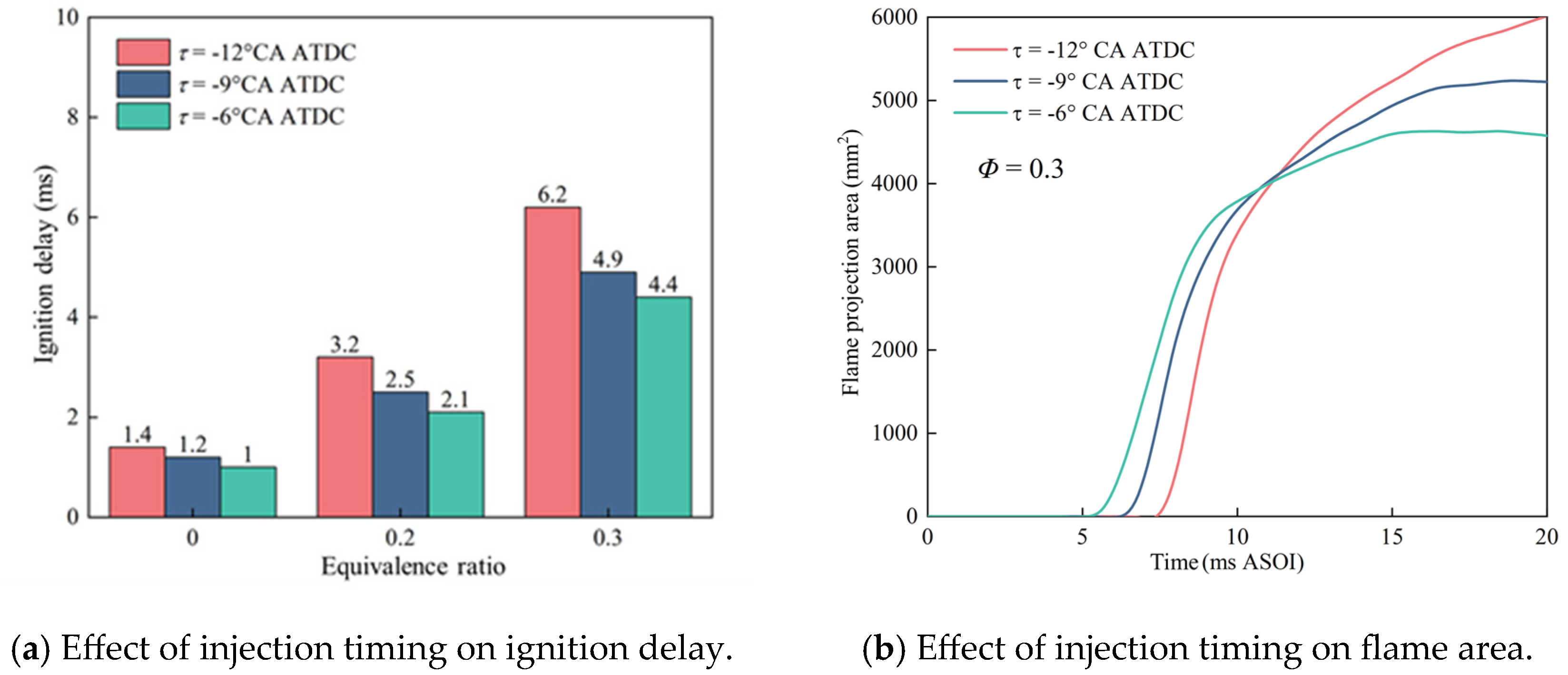
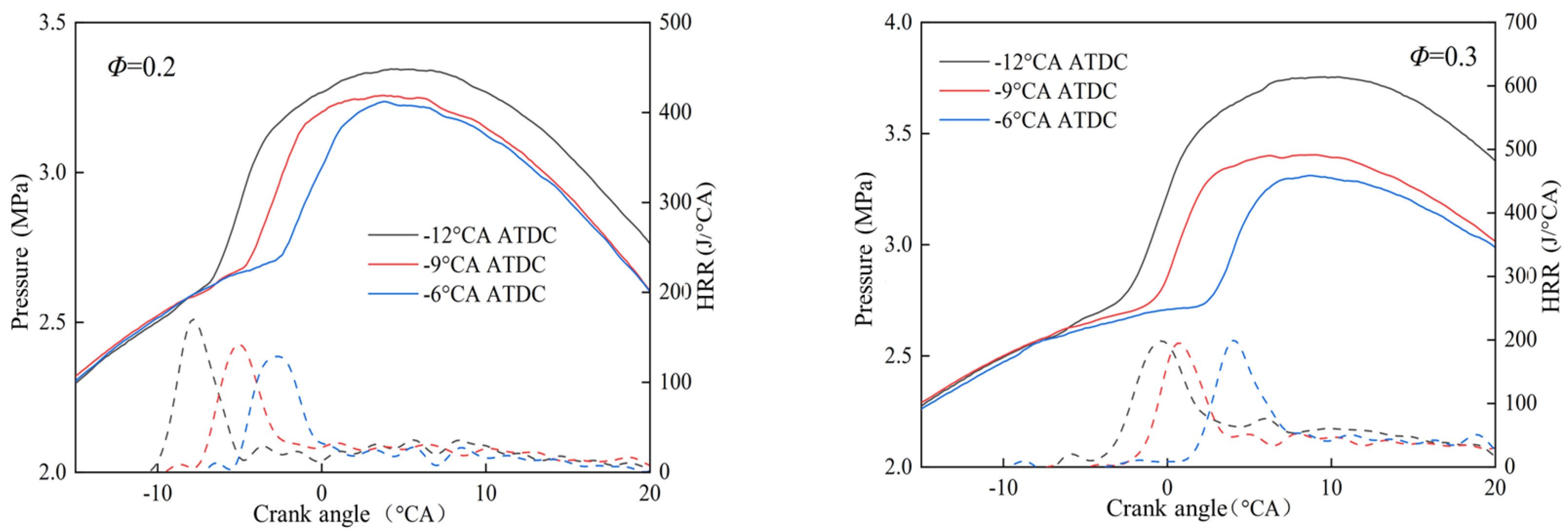
The closer the injection timing is to the TDC, the shorter the ignition delay is, the faster the flame’s early development is, and the larger the projected flame area is. The advancement of the injection timing makes the premixture more uniform. Although the ignition delay is prolonged, the projected flame area grows fast in the later stage, and the total projected flame area is larger. The advancement of the injection timing increases the maximum combustion pressure and the peak heat release rate.
(3)
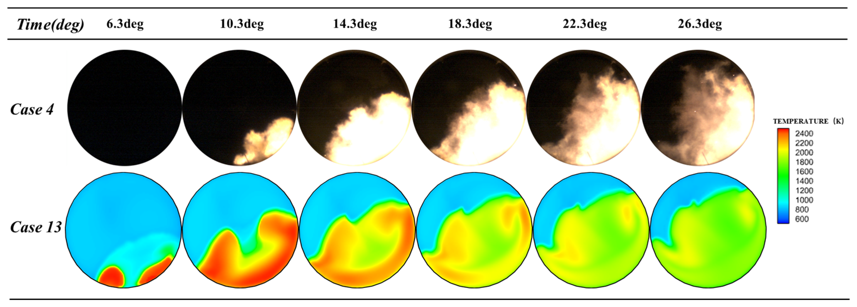
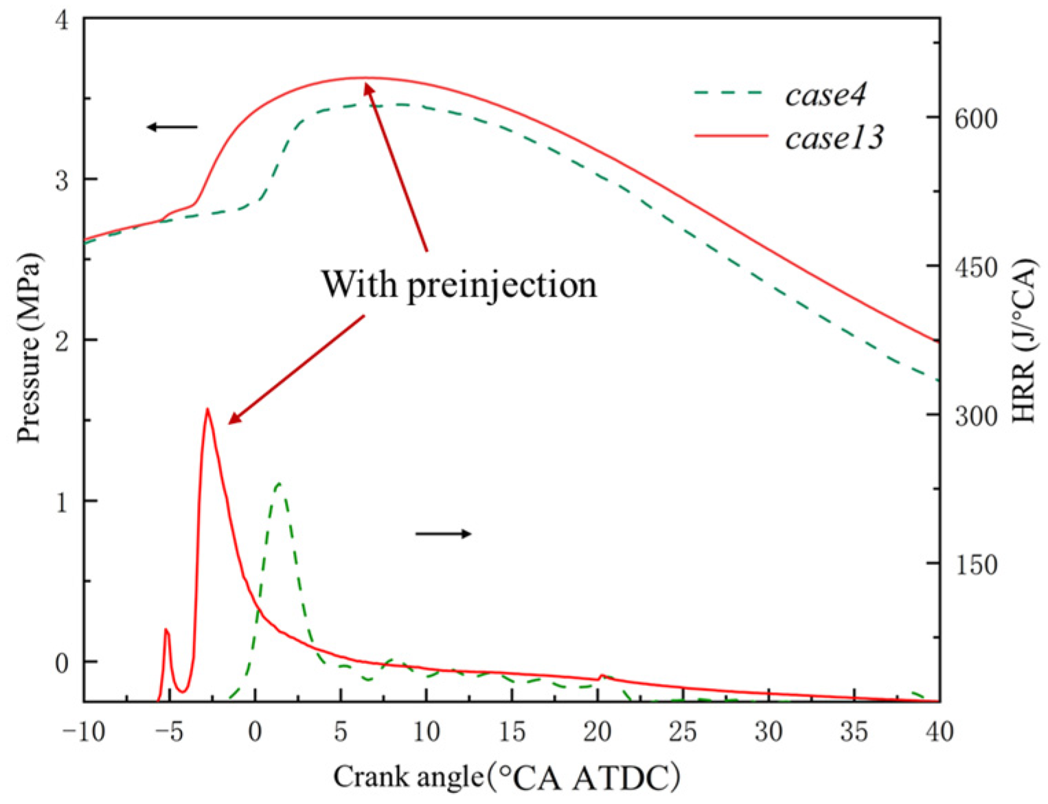
The strategy of pre-injecting a portion of diesel can effectively shorten the ignition delay, resulting in increased cylinder pressure and heat release rate. Additionally, the heat release rate presents a double-peak feature under this strategy. It is speculated that the first peak is likely caused by the low-temperature reaction of pre-injected diesel and the second peak is caused by the heat release of the ammonia premixture.

Author Contributions

Conceptualization, J.T.; Data curation, B.J.; Formal analysis, X.G. and Q.Z.; Funding acquisition, J.T.; Investigation, H.Y. and S.S.; Methodology, X.G. and Q.Z.; Project administration, Z.C.; Visualization, S.S.; Writing—original draft, Q.Z. and B.J.; Writing—review and editing, X.G. and Z.C. All authors have read and agreed to the published version of the manuscript.

Funding

This research was funded by National Natural Science Foundation of China, grant number 52071064.

Data Availability Statement

The data presented in this study are available upon request from the corresponding author.

Conflicts of Interest

Authors Xianli Gao and Baofu Jia were employed by the company Zichai Power Co., Ltd. The remaining authors declare that the research was conducted in the absence of any commercial or financial relationships that could be construed as a potential conflict of interest.

References

  1. Al-Hamamre, Z.; Yamin, J. The Effect of Hydrogen Addition on Premixed Laminar Acetylene–Hydrogen–Air and Ethanol–Hydrogen—Air Flames. Int. J. Hydrog. Energy 2013, 38, 7499–7509. [Google Scholar] [CrossRef]
  2. Lv, X.; Yan, X.; Lei, M.; Hou, Y.; Chen, L.; Wang, Y.; Qi, C.; Yu, X.; Yu, J. Propagation of High-Speed Hydrogen-Air Combustion Waves through Inert Gases. Fuel 2023, 345, 128205. [Google Scholar] [CrossRef]
  3. Kurien, C.; Mittal, M. Review on the Production and Utilization of Green Ammonia as an Alternate Fuel in Dual-Fuel Compression Ignition Engines. Energy Convers. Manag. 2022, 251, 114990. [Google Scholar] [CrossRef]
  4. Shu, T.; Xue, Y.; Zhou, Z.; Ren, Z. An Experimental Study of Laminar Ammonia/Methane/Air Premixed Flames Using Expanding Spherical Flames. Fuel 2021, 290, 120003. [Google Scholar] [CrossRef]
  5. Dai, L.; Gersen, S.; Glarborg, P.; Mokhov, A.; Levinsky, H. Autoignition Studies of NH3/CH4 Mixtures at High Pressure. Combust. Flame 2020, 218, 19–26. [Google Scholar] [CrossRef]
  6. Gray, J.T., Jr.; Dimitroff, E.; Meckel, N.T.; Quillian, R.D., Jr. Ammonia Fuel-Engine Compatibility and Combustion. SAE Trans. 1966, 660156. [Google Scholar]
  7. Wen, M.; Liu, H.; Cui, Y.; Ming, Z.; Feng, L.; Wang, G.; Yao, M. Study on Combustion Stability and Flame Development of Ammonia/n-Heptane Dual Fuel Using Multiple Optical Diagnostics and Chemical Kinetic Analyses. J. Clean. Prod. 2023, 428, 139412. [Google Scholar] [CrossRef]
  8. Wu, B.; Zi, Z.; Jin, S.; Pei, Y.; Wang, D. Effect of Diesel Injection Strategy and Ammonia Energy Fraction on Ammonia-Diesel Premixed-Charge Compression Ignition Combustion and Emissions. Fuel 2024, 357, 129785. [Google Scholar] [CrossRef]
  9. Niki, Y.; Nitta, Y.; Sekiguchi, H.; Hirata, K. Diesel Fuel Multiple Injection Effects on Emission Characteristics of Diesel Engine Mixed Ammonia Gas into Intake Air. J. Eng. Gas Turbines Power 2019, 141, 061020. [Google Scholar] [CrossRef]
  10. Li, T.; Zhou, X.; Wang, N.; Wang, X.; Chen, R.; Li, S.; Yi, P. A Comparison between Low- and High-Pressure Injection Dual-Fuel Modes of Diesel-Pilot-Ignition Ammonia Combustion Engines. J. Energy Inst. 2022, 102, 362–373. [Google Scholar] [CrossRef]
Figure 1. Schematic diagram of the constant-volume-spray optical experimental platform, RCEM optical experimental platform, and the combustion test terminal.
Fluids 09 00224 g001aFluids 09 00224 g001b
Figure 2. The penetration distance of diesel in different gas atmospheres.
Fluids 09 00224 g002
Figure 3. Penetration distance calibration of diesel spray.
Fluids 09 00224 g003
Figure 4. Diesel spray profile.
Fluids 09 00224 g004
Figure 5. Comparison diagram of the cylinder pressure based on experimental and CFD calculations.
Fluids 09 00224 g005
Figure 6. Comparison diagram of images based on the experimental and CFD calculations.
Fluids 09 00224 g006
Figure 7. Effects of the injection pressure on the premixed ammonia flame.
Fluids 09 00224 g007
Figure 8. Effects of injection pressure on premixed-ammonia-flame-ignition delay period and projected flame area.
Fluids 09 00224 g008
Figure 9. Effects of injection pressure on cylinder pressure and heat release rate. (a) Effect of injection pressure on cylinder pressure and heat release rate at Φ = 0.2. (b) Effect of injection pressure on cylinder pressure and heat release rate at Φ = 0.3.
Fluids 09 00224 g009
Figure 10. Effects of injection timing on premixed ammonia flame.
Fluids 09 00224 g010
Figure 11. Effects of injection timing on premixed ammonia flame ignition delay period and projected flame area.
Fluids 09 00224 g011
Figure 12. Effects of injection timing on cylinder pressure and heat release rate. (a) Effect of injection pressure on cylinder pressure and heat release rate at Φ = 0.2. (b) Effect of injection pressure on cylinder pressure and heat release rate at Φ = 0.3.
Fluids 09 00224 g012
Figure 13. Effects of pre-injection strategy on premixed ammonia flame.
Fluids 09 00224 g013
Figure 14. Effects of pre-injection strategy on cylinder pressure and heat release rate.
Fluids 09 00224 g014
Table 1. Characteristics of ammonia and other fuels.
GasolineDieselMethaneHydrogenAmmonia
Low heating value (MJ/kg)44.543.438.1120.118.8
Flammability limit (Vol.%)1.4–7.60.6–5.55–154–7516–25
Laminar burning velocity at Φ = 1.0 (cm/s)5886383517
Autoignition temperature (°C)300230450571651
Minimum ignition energy (MJ)0.140.0188.0
Octane rating90–98107>130111
Latent heat of vaporization (KJ/kg)71.7847.86104.81369
Table 2. Experimental conditions of diesel spray characteristics in ammonia/nitrogen mixture atmosphere.
Temperature/KPressure/MPaEquivalence RatioInjection Pulse Width/msInjection
Pressure/MPa
17502.50280
27502.50.5280
Table 3. Experimental conditions for diesel-ignited ammonia/air combustion.
Equivalence RatioNozzle
Diameter/mm
Injection
Pressure/MPa
Diesel Injection Timing/degPre-SprayInjection Pulse Width/msResearch
Approach
10.20.1260−9No3.5Experiment
20.20.1280−9No2.8Experiment
30.20.12100−9No2.3Experiment
40.30.1260−9No3.5Experiment
50.30.1280−9No2.8Experiment
60.30.12100−9No2.3Experiment
70.20.1260−6No3.5Experiment
80.20.1260−12No3.5Experiment
90.30.1260−6No3.5Experiment
100.30.1260−12No3.5Experiment
110.20.1560−9No2.15Experiment
120.30.1560−9No2.15Experiment
130.30.1260−14, −9Yes3.5Simulation
Table 4. Simulated calculation sub-models.
Model NameSub-Models
TurbulenceRNG k-ε
Spray break-upKH-RT
EvaporationFrossling
Droplet collisionNTC
Spray interactionWall film
Turbulence actionO’Rourke
Combustion modelSAGE
Nitrogen oxide emissionExtended Zeldovich
Soot emissionHiroyasu
Disclaimer/Publisher’s Note: The statements, opinions and data contained in all publications are solely those of the individual author(s) and contributor(s) and not of MDPI and/or the editor(s). MDPI and/or the editor(s) disclaim responsibility for any injury to people or property resulting from any ideas, methods, instructions or products referred to in the content.

