

Fused Deposition Modelling of Thermoplastic Polymer Nanocomposites: A Critical Review


Abstract
1. Introduction
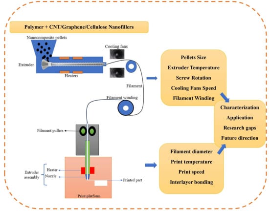
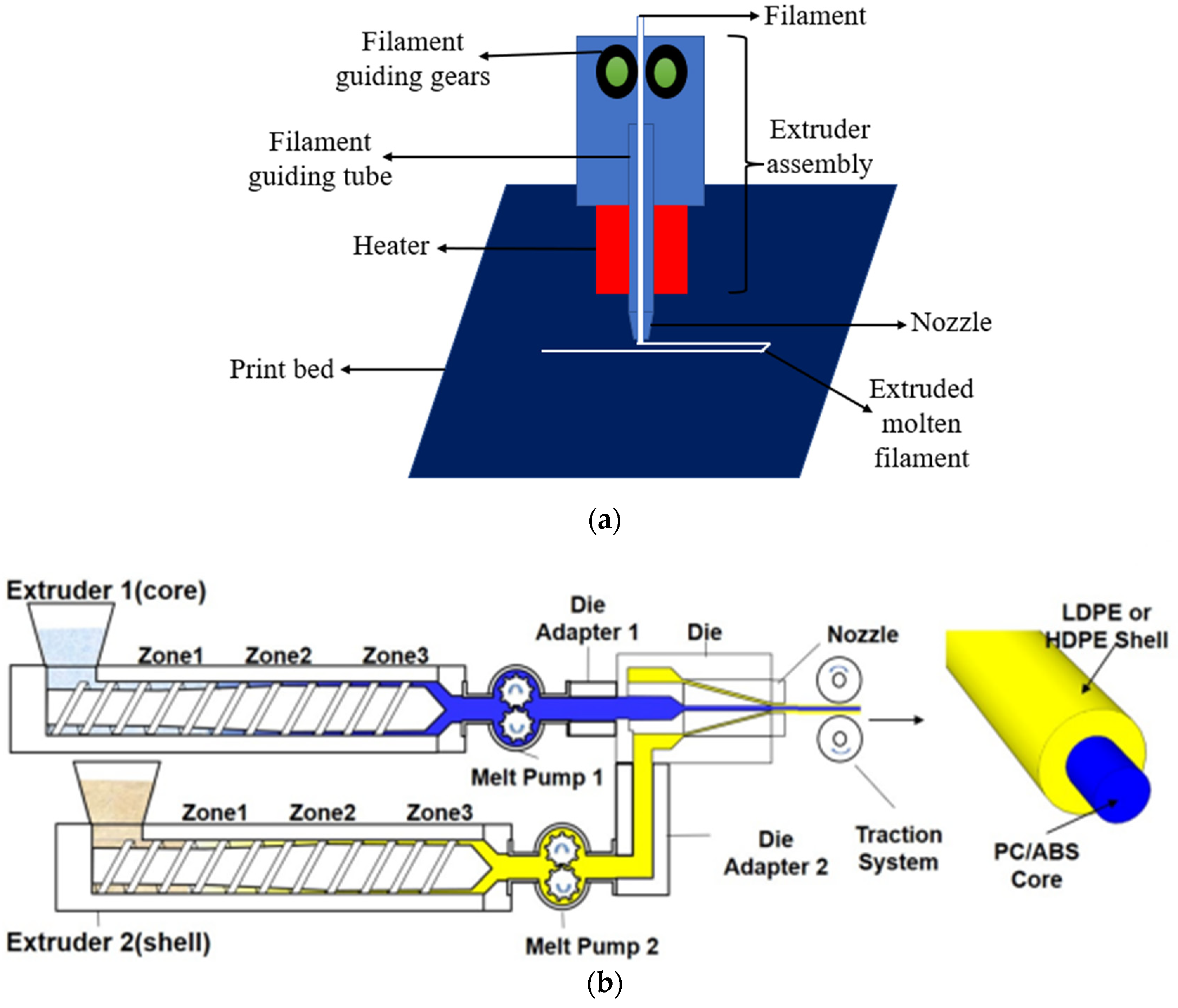
2. FDM Process
2.1. FDM Filament Production
2.2. Chemical Solution Method
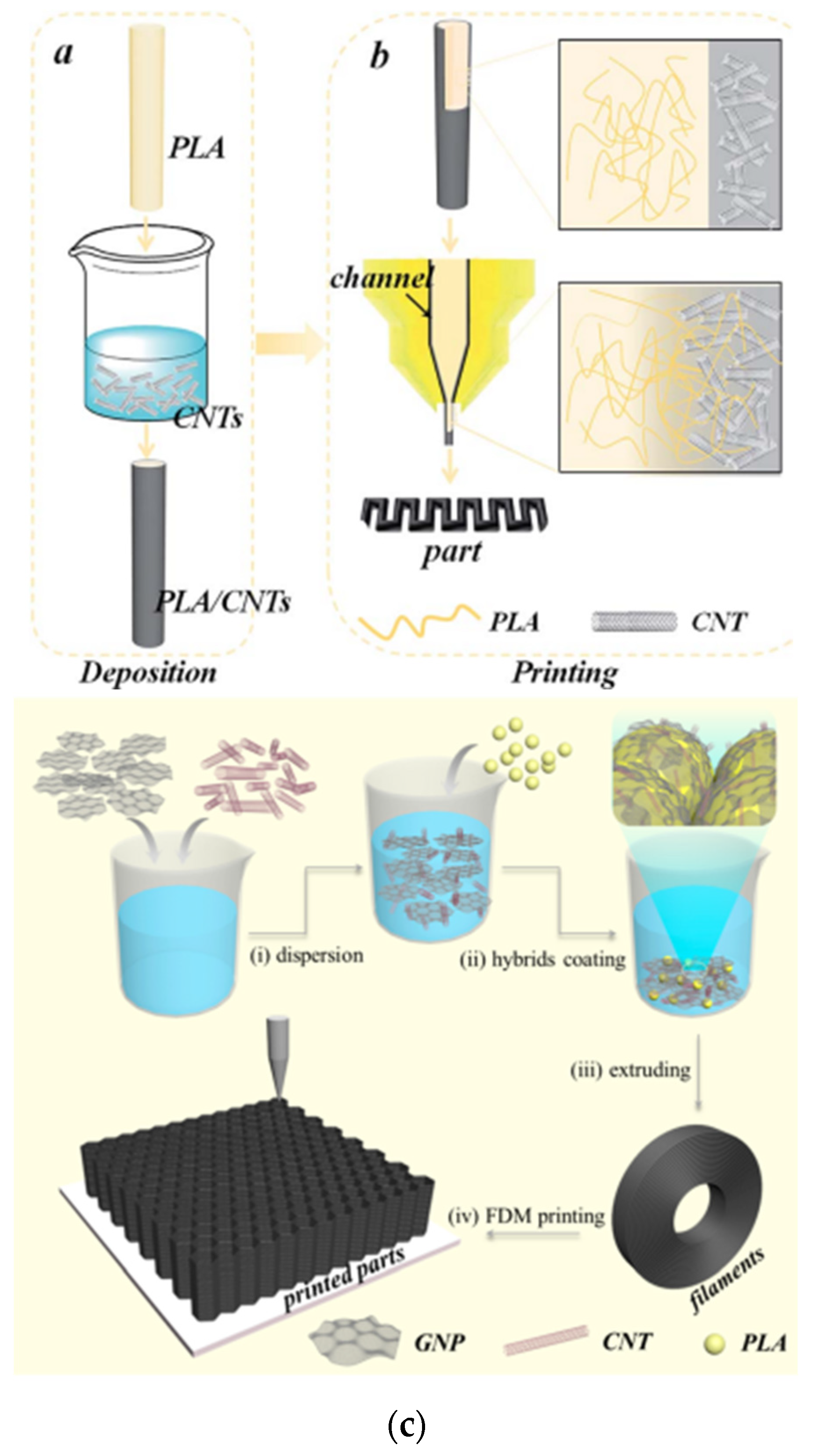
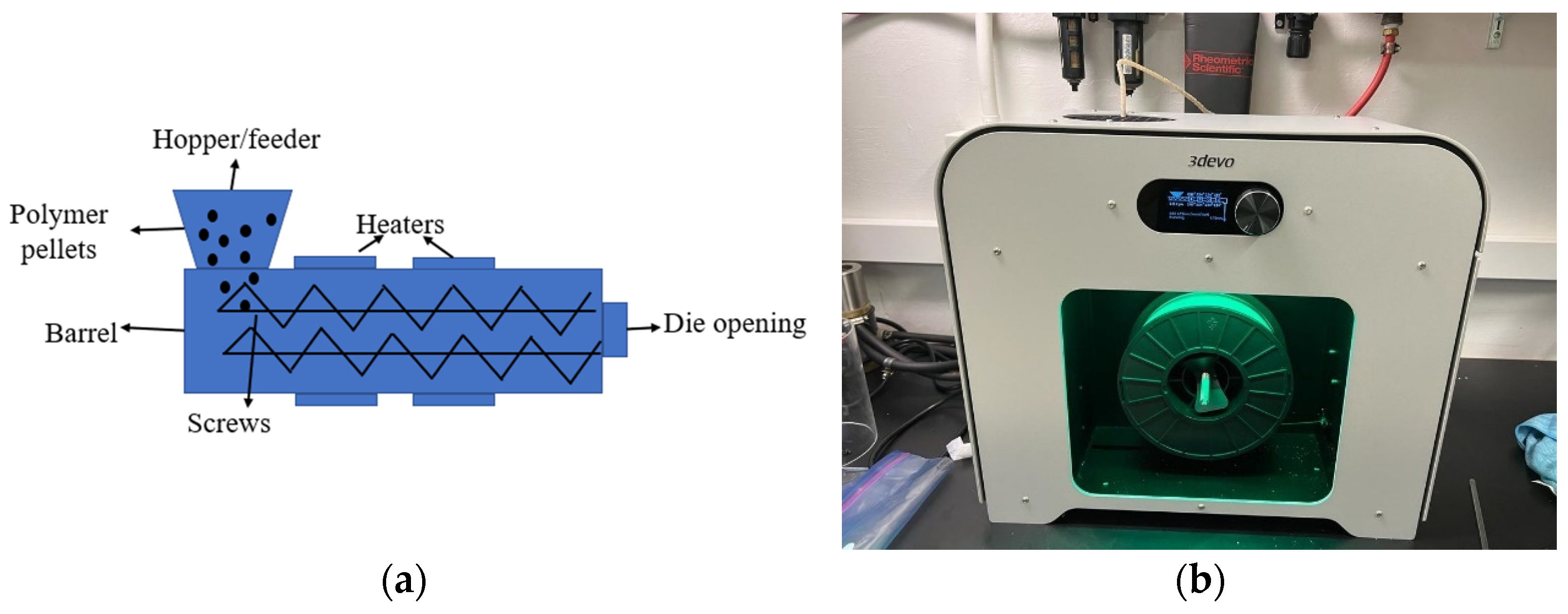
2.3. Mechanical Processing
2.4. Extrusion
3. Filler Types
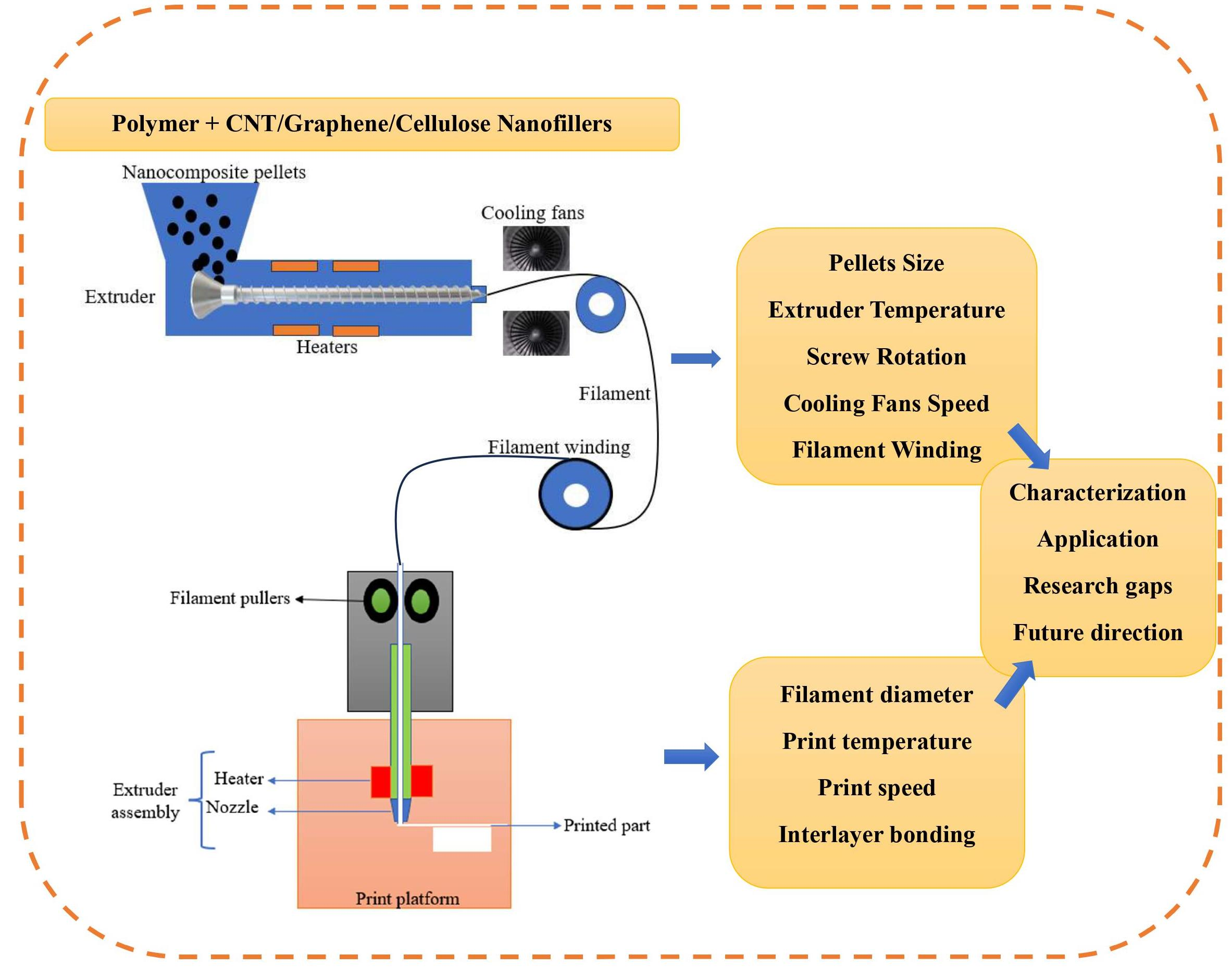
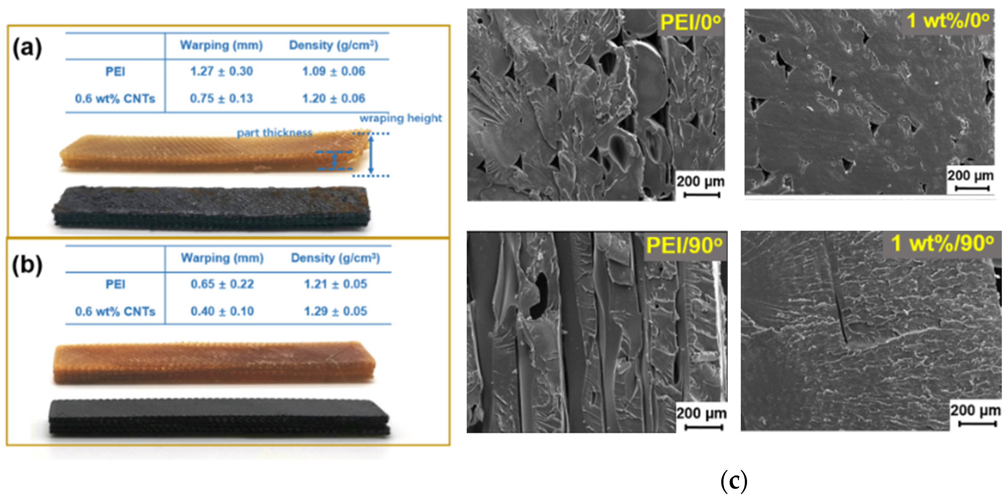
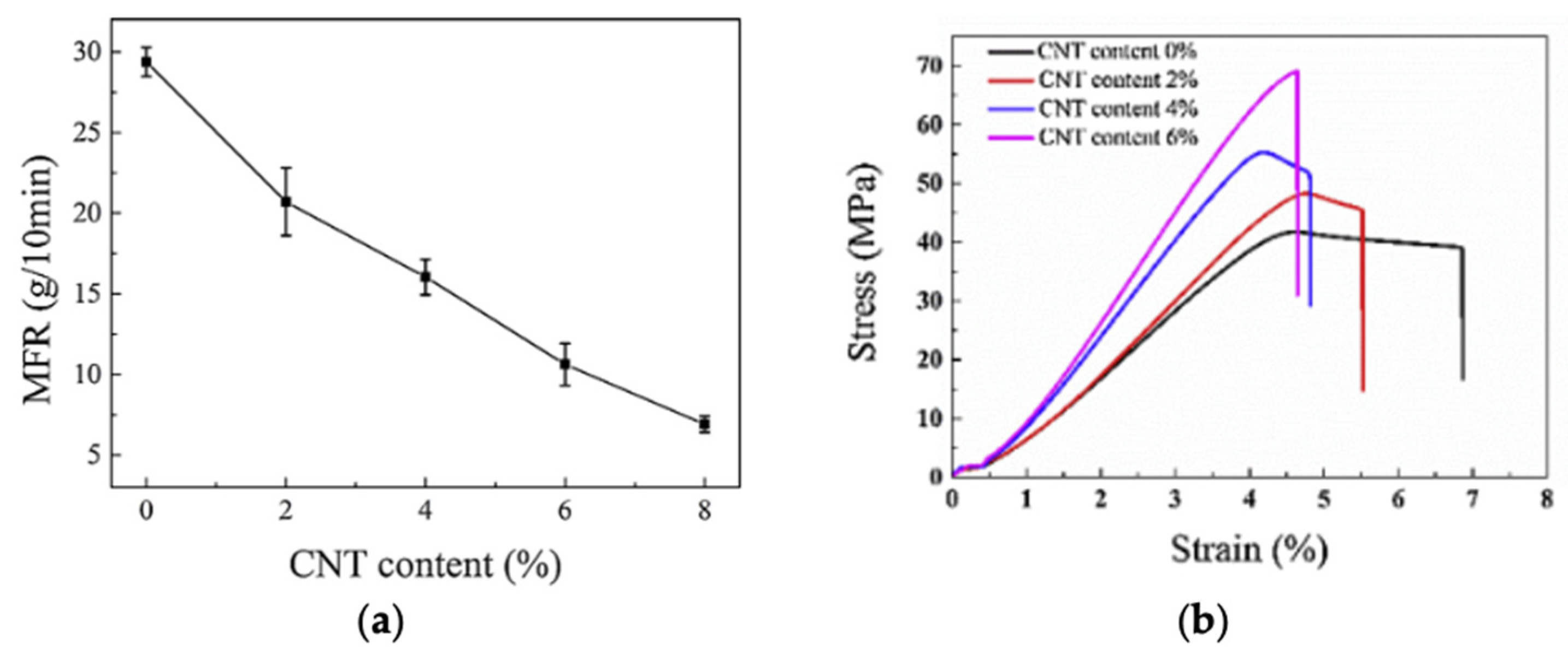
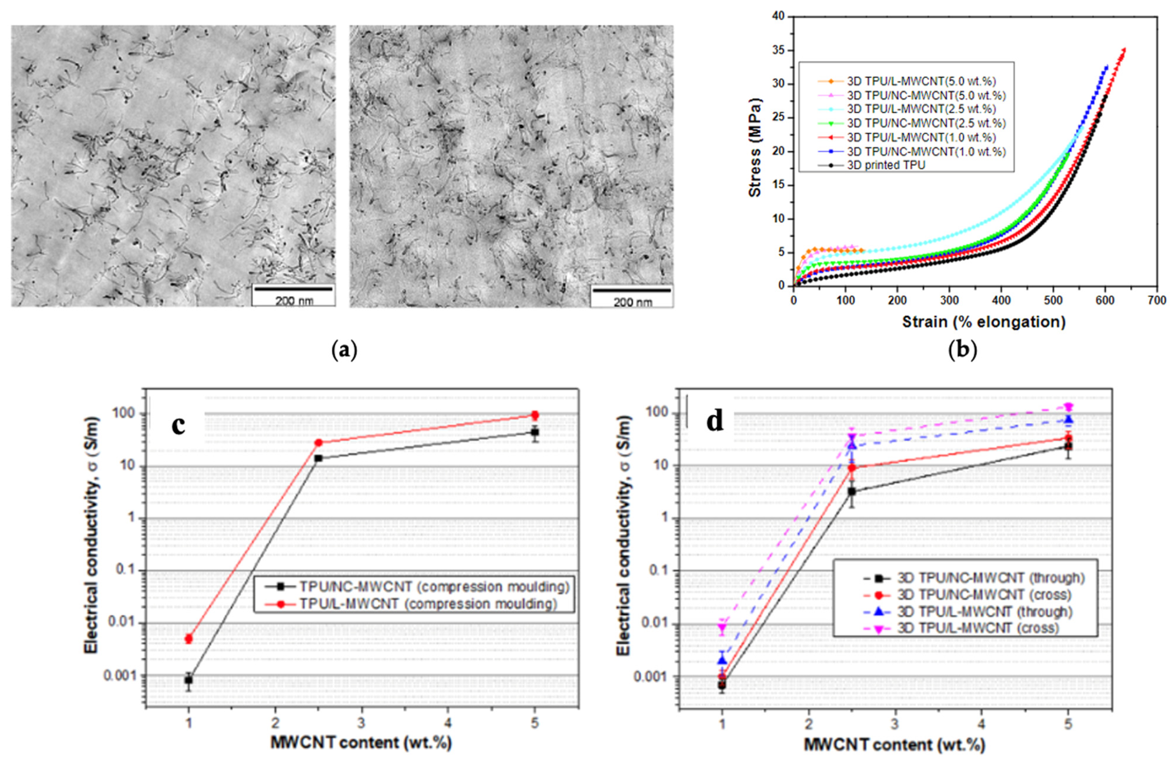
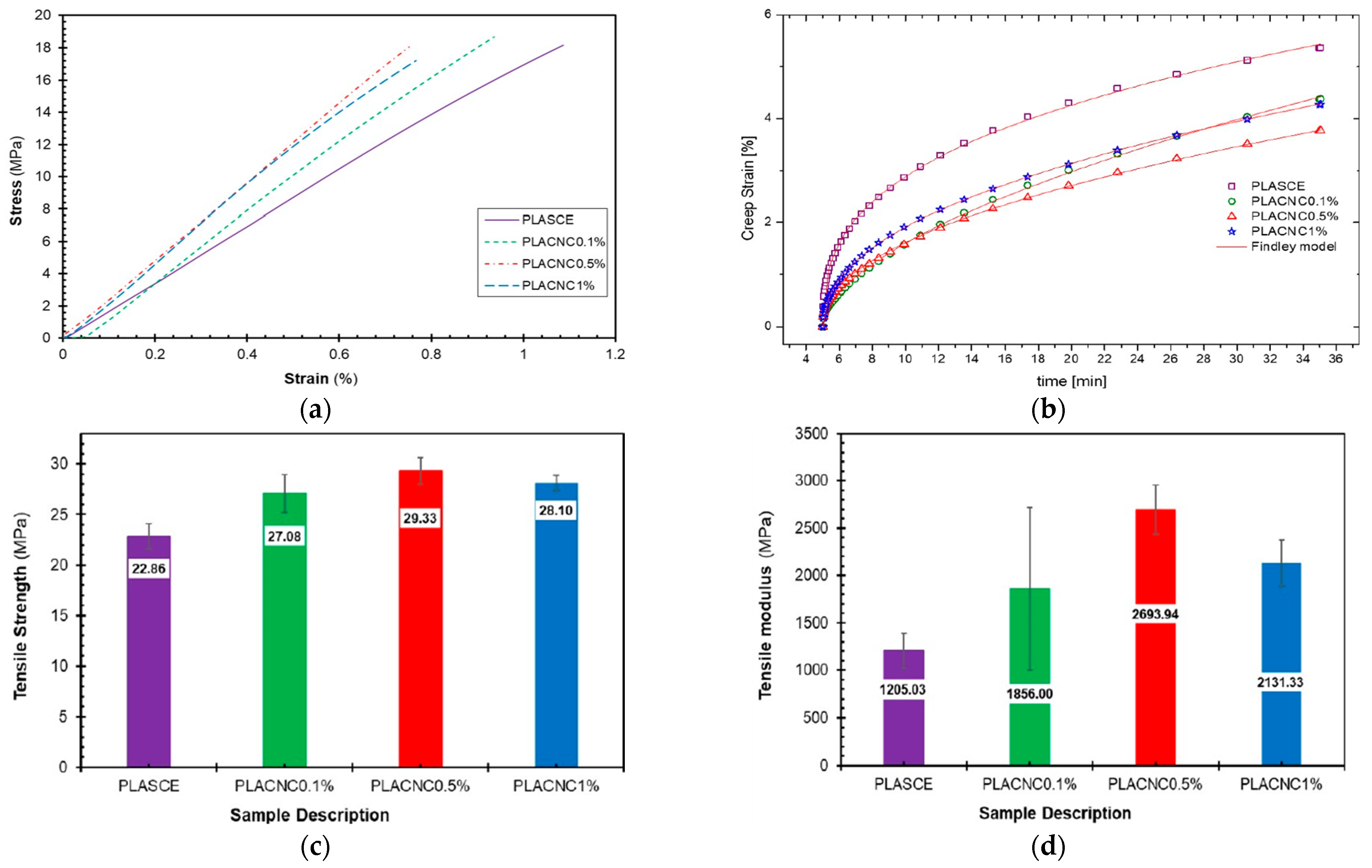
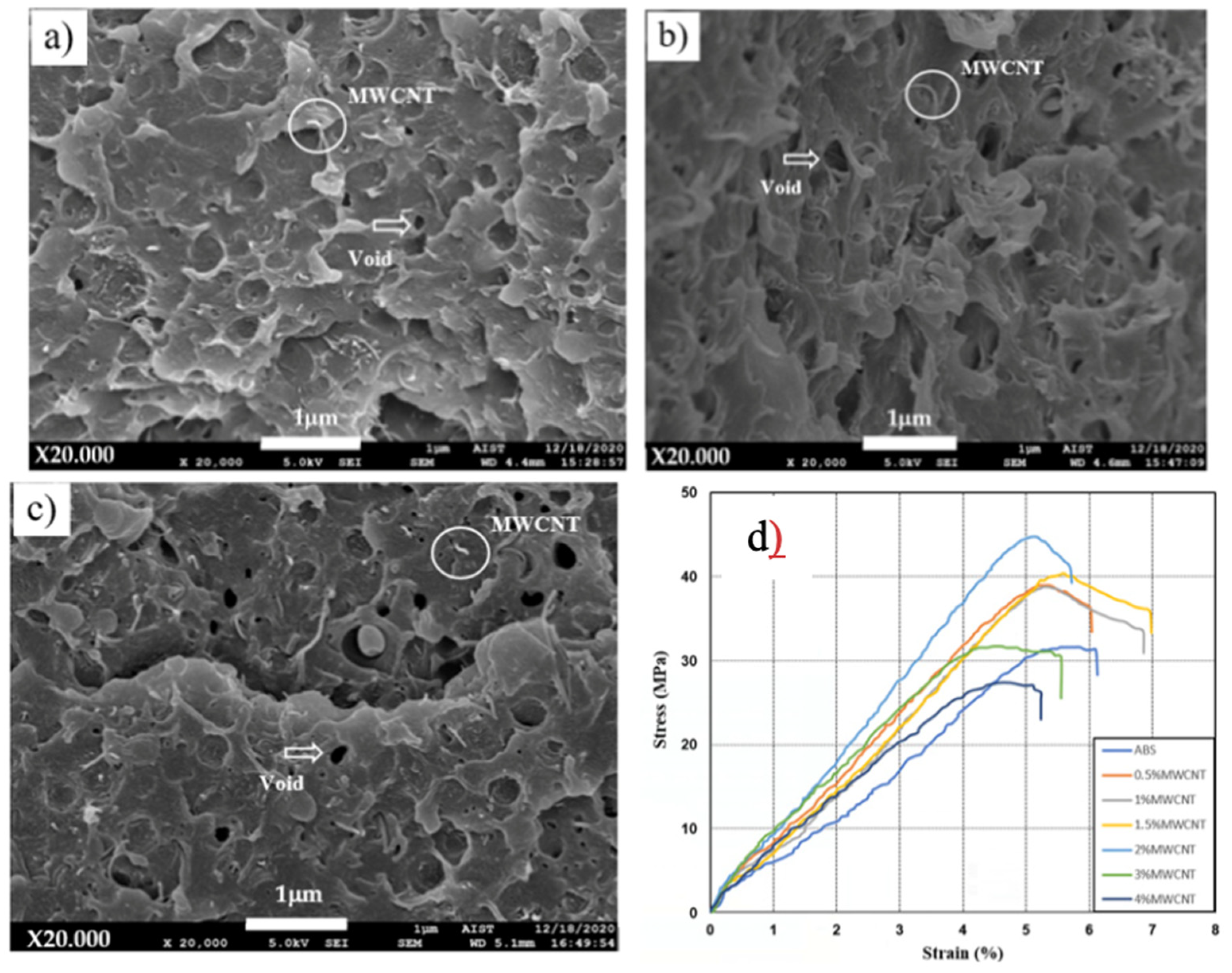
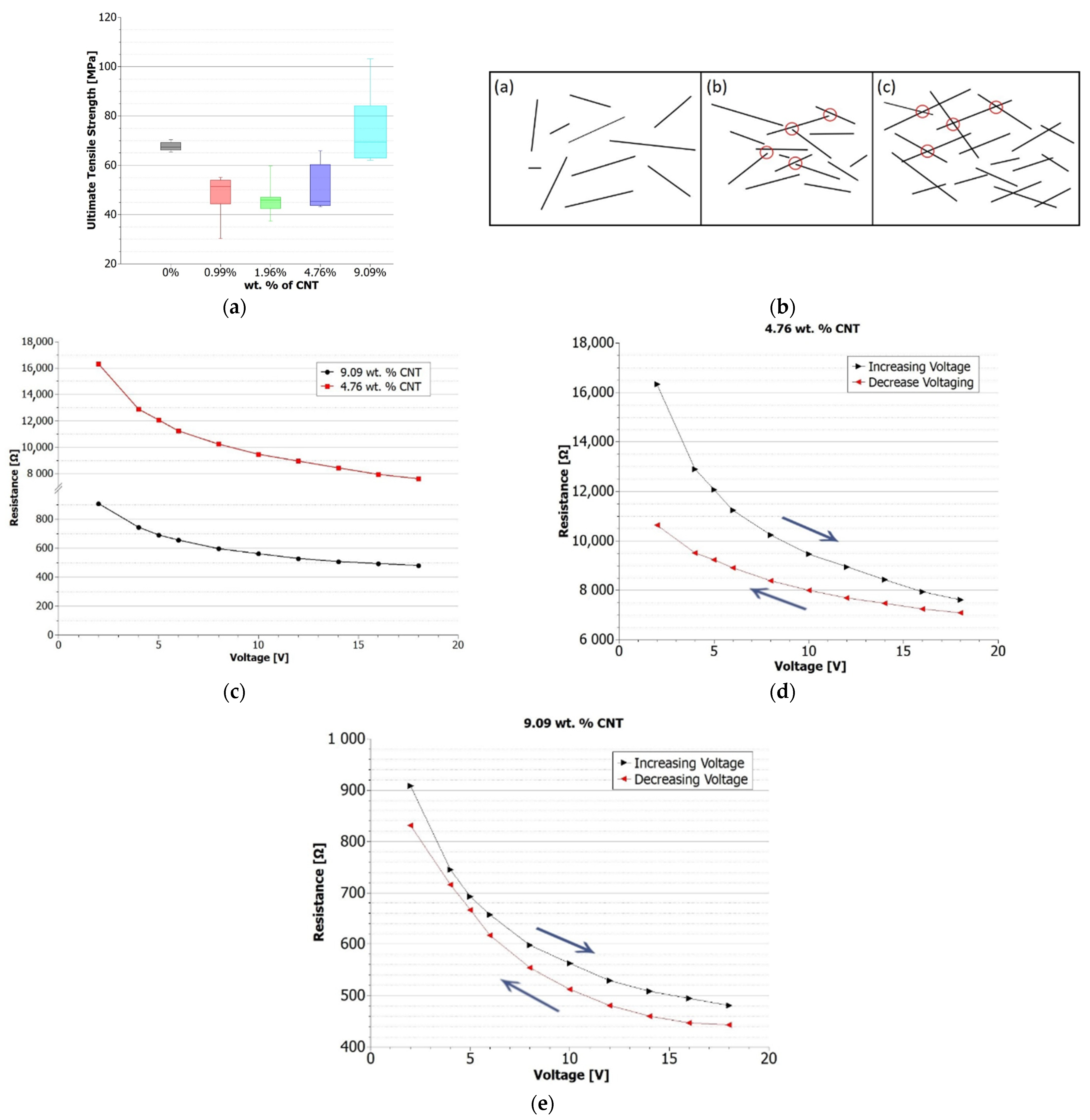
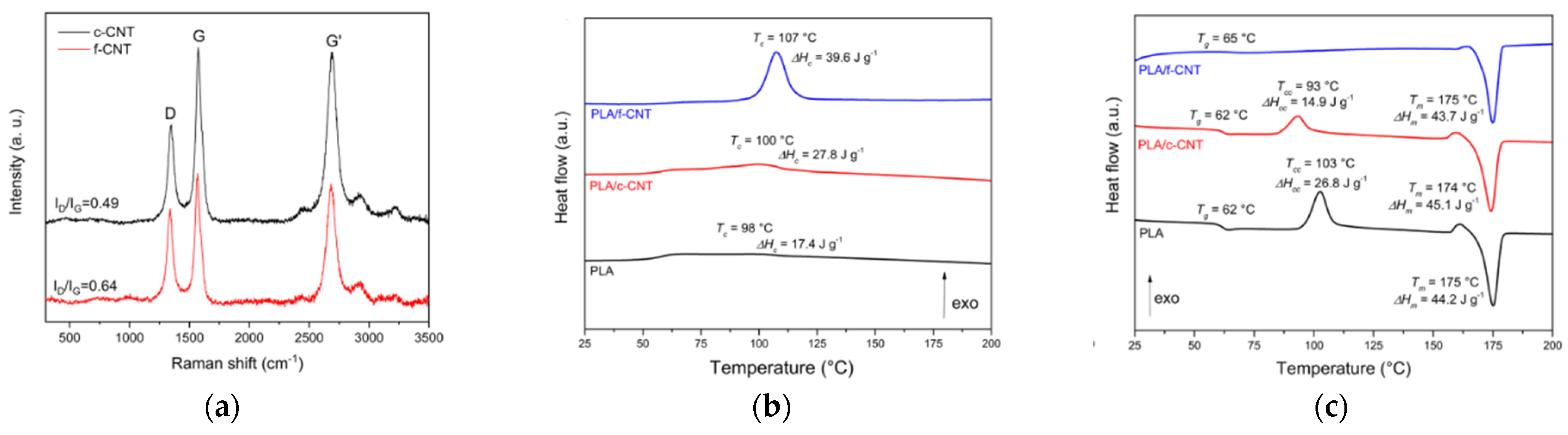
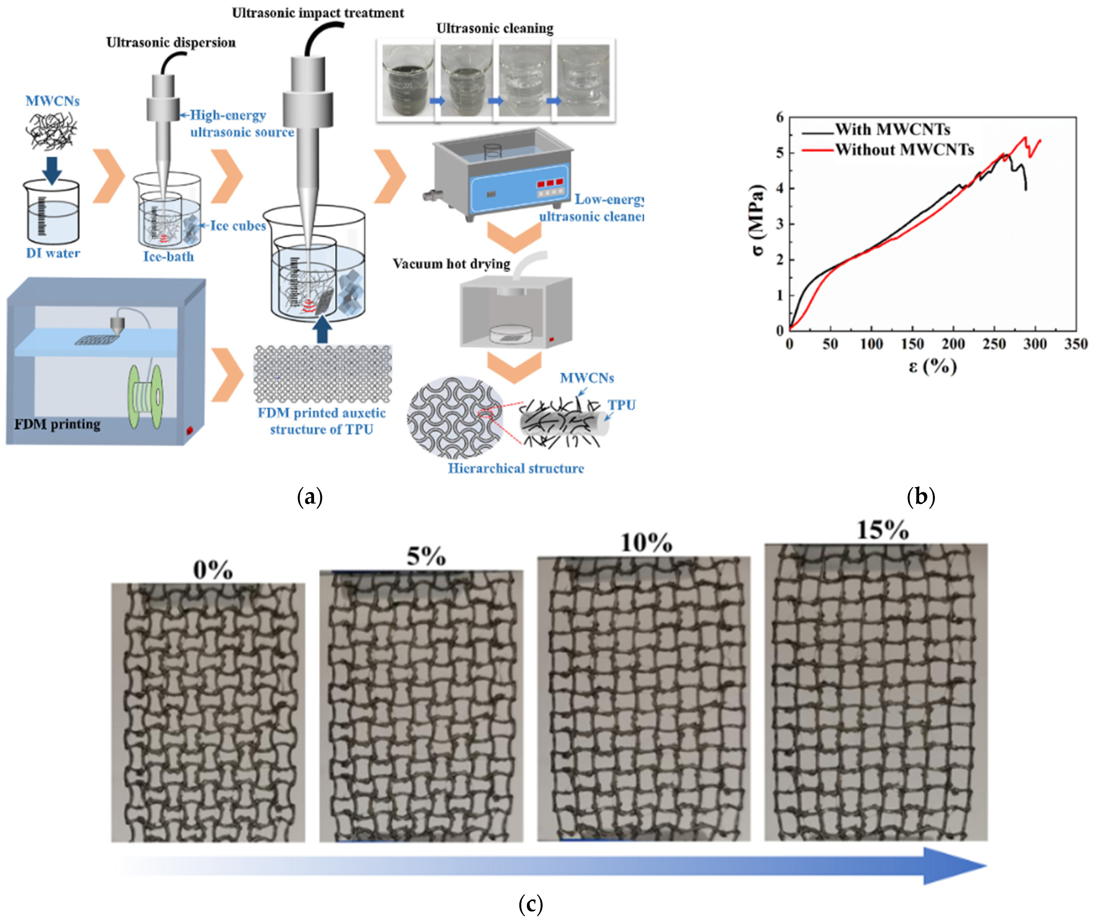
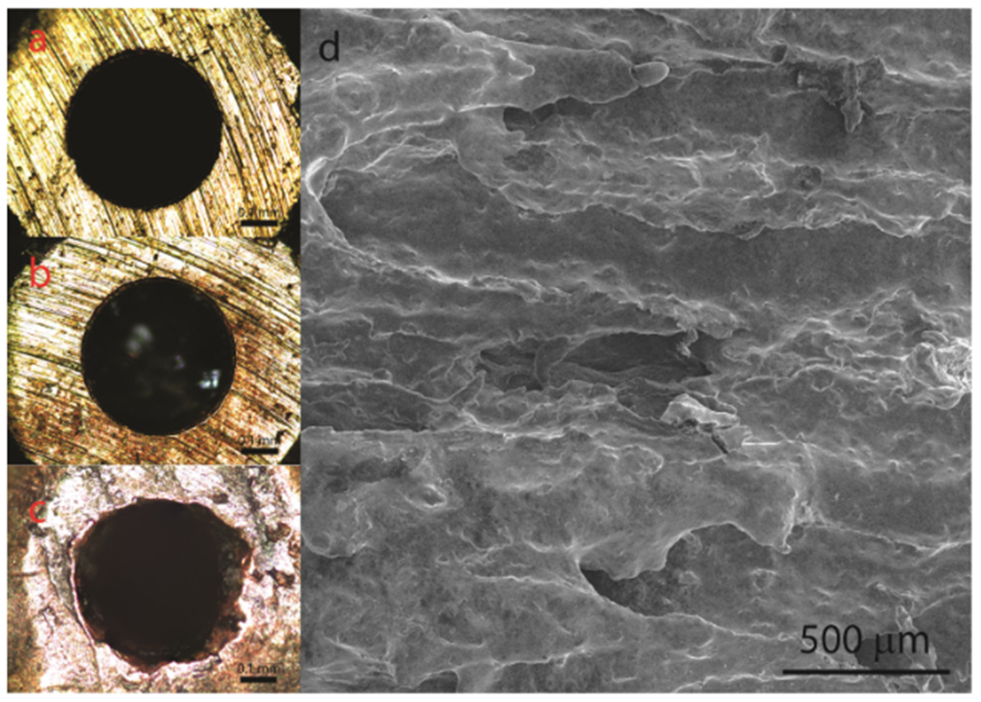
3.1. Carbon Nanotube Polymer Nanocomposite
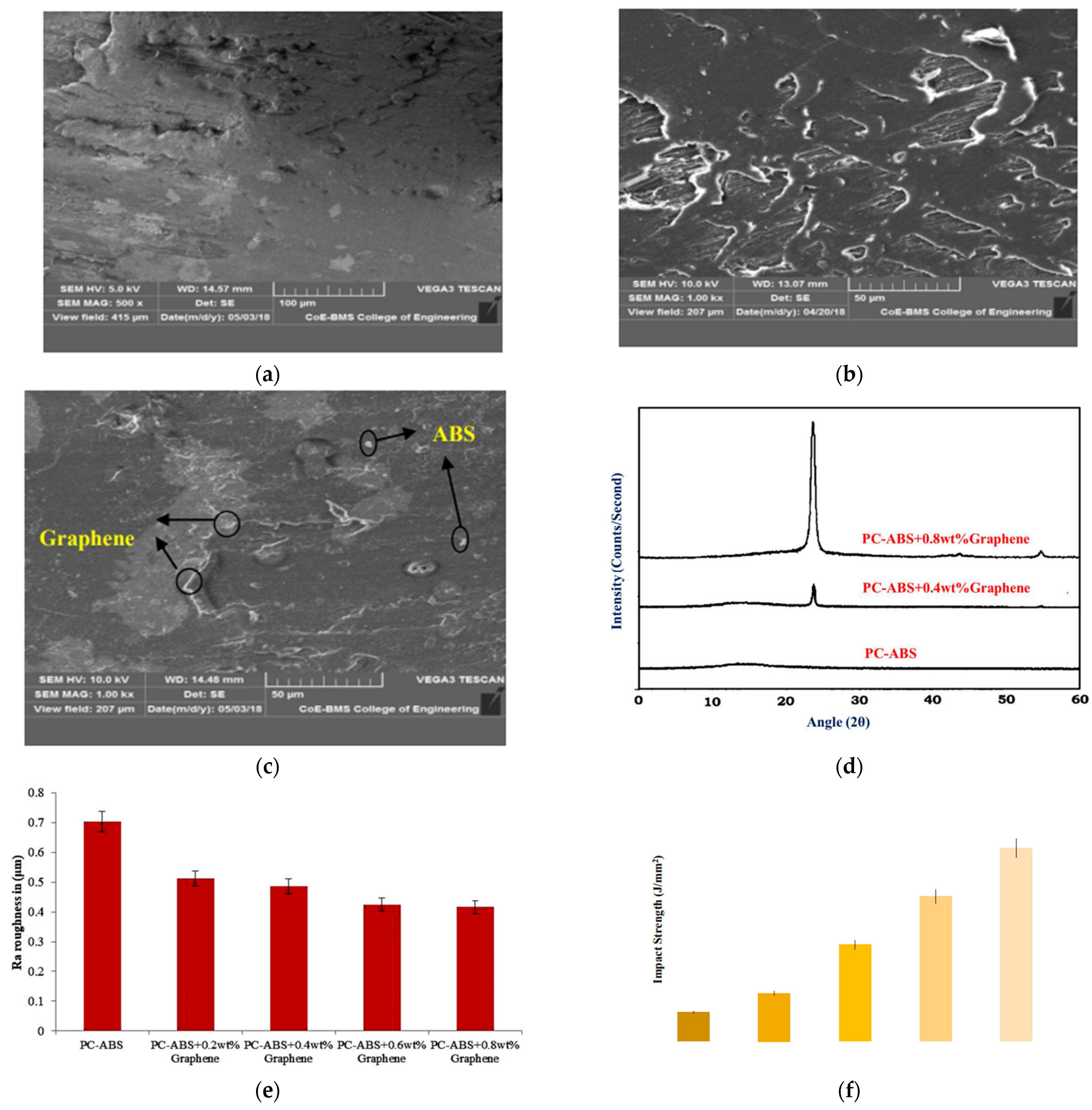
3.2. Graphene Polymer Nanocomposites
3.3. Cellulose Polymer Nanocomposites

| Matrix | Method | Properties | Ref. |
|---|---|---|---|
| ABS + CNT | Chemical solution | Electrical and mechanical properties, mechanical percolation threshold (9%), electrical threshold percolation (4.76%) | [48] |
| ABS + CNT | Mechanical (melt mixing) | Rheological, morphological, and mechanical properties, 2% CNT increases strength by 42% | [68] |
| ABS + CNT | Mechanical (melt mixing) | Thermal, electrical, and mechanical properties for SWCNTs and MWCNTs | [49] |
| ABS + Graphene | Mechanical (melt mixing) | Recycled ABS-graphene for rheological, thermal, magnetometric, and mechanical properties | [150] |
| ABS + Reduced graphene oxide (rGO) | Chemical solution | Interface stresses | [111] |
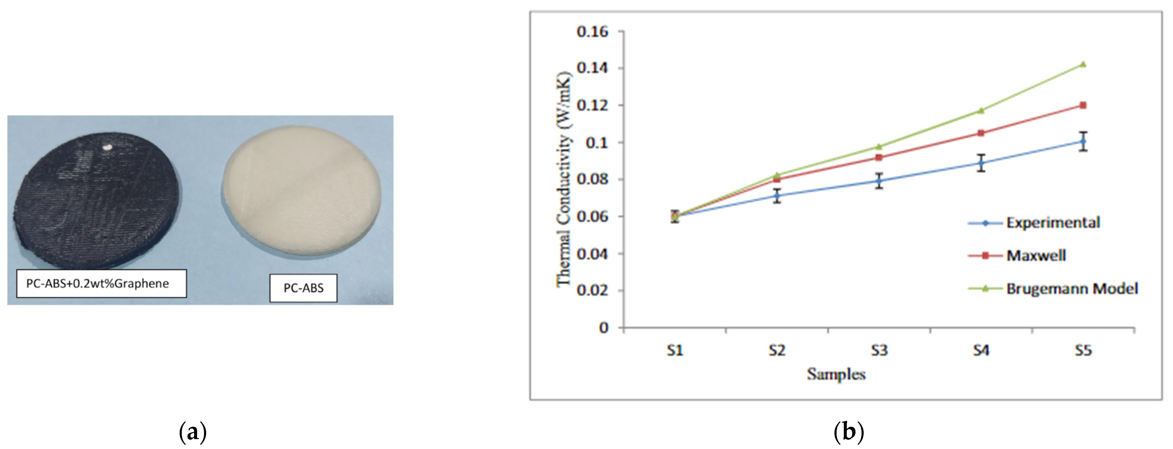
| PC-ABS + Graphene | Mechanical (melt mixing) | Tensile strength, low-velocity impact strength, and surface roughness | [109] |
| PC-ABS + Graphene | Mechanical (melt mixing) | Thermal conductivity | [106] |
| ABS + Graphene/CNTs | Mechanical (melt mixing) | Stiffness, creep stability processability, tensile strength, and electrical properties | [52] |
| Polybutylene terephthalate (PBT) + Graphene/CNTs | Chemical solution | Printability, electrical conductivity, and mechanical stability | [64] |
| ABS + Graphene | Mechanical (melt mixing) | Mechanical (tensile, flexural, and impact) and electrical properties | [105] |
| Polyethylene + Graphene | Mechanical (melt mixing) | Thermal conductivity and mechanical properties | [50] |
| Polyurethane + Cellulose/graphene | Chemical solution | Morphological, thermal, mechanical, and thermoelectric properties | [95,147] |
| PLA + CNTs/graphene | Mechanical (melt mixing) | Electrical and thermal properties | [116] |
| PLA + CNTs/graphene | Chemical solution | Electromagnetic shielding | [45] |
| Polypropylene + Graphene | Mechanical (melt mixing) | X-ray scattering and shear study | [115] |
| ABS + CNTs | Mechanical (melt mixing) | Morphological, electrical, and mechanical properties | [67] |
| Polyamide + CNTs | Chemical solution/mechanical | Electromagnetic wave absorption and mechanical properties | [82] |
| PVDF + CNTs | Mechanical (mixing) | Piezoelectric and mechanical properties for energy harvesting | [83] |
| Polybutylene Terephthalate (PBT)/ABS + CNTs | Mechanical (mixing) | Mechanical and morphological properties | [99] |
| Polypropylene random copolymer (PPR) + CNTs | Mechanical (mixing) | Piezoresistive properties (crystallinity) | [86] |
| Polyetherimide (PEI) + CNTs | Mechanical (mixing) | Bond strength, porosity of parts, electrical conductivity | [87,151] |
| PLA + CNTs | Chemical/mechanical (mixing) | Thermal, mechanical (dynamic analysis) | [92] |
| ABS + CNTs | Mechanical (mixing) | Morphological, thermal, and mechanical properties | [71,78] |
| ABS + CNTs | Mechanical (mixing) | Structural, morphological, and dynamic mechanical properties | [72] |
| Polyphenylene sulphide + CNTs | Chemical solution | Tensile, bending, diffusion, and thermal properties | [79] |
| PLA + CNTs | Mechanical (mixing) | Thermal, mechanical, and electrical | [88] |
| PLA + Graphene/CNTs | Local enrichment | Electrical conductivity, electromagnetic interference shielding | [45,46] |
| ABS + Carbon nanofibre | Mechanical (mixing) | Tensile, dimensional, surface properties | [152] |
| PLA/TPU + CNTs | Mechanical (mixing) | Morphological, interfacial, and mechanical properties | [51] |
| TPU + Conductive carbon | Mechanical (mixing) | Biocompatibility, thermal, mechanical | [153] |
| TPU + CNTs | Mechanical (mixing) | Warping, interlayer adhesion, thermoelectric properties | [95,98] |
| PLA + Cellulose nanocrystals (CNC) | Mechanical (mixing) | Shape memory properties, melt processibility, and inter-fuse adhesion | [135,136] |
| PLA + Cellulose nanofibrils (CNF) | Mechanical (mixing) | Thermal stability, mechanical performance, and water absorption | [43] |
| PLA + Nanocrystalline cellulose (NCC) | Mechanical (mixing) | Tensile and thermal properties | [137] |
| TPU/polycaprolactone (PCL) + CNC | Chemical solution | Chemical structure, mechanical, and thermal properties | [149] |
| Poly(3-hydroxybutyrate) (PHB)/PLA + Cellulose fibres (CF) | Mechanical mixing | Structural, morphological, mechanical | [148] |
| PLA/TPU + CNC | Mechanical mixing | Melt processibility, shear, and stretching effect | [138] |
| High-density polyethylene (HDPE) + Cellulose fibres (CF) | Mechanical mixing/chemical solution | Warping, morphological, and mechanical properties | [139] |
4. Discussion and Concluding Remarks
5. Concluding Remarks
Author Contributions
Funding
Acknowledgments
Conflicts of Interest
References
- Sztorch, B.; Brząkalski, D.; Pakuła, D.; Frydrych, M.; Špitalský, Z.; Przekop, R.E. Natural and Synthetic Polymer Fillers for Applications in 3D Printing—FDM Technology Area. Solids 2022, 3, 508–548. [Google Scholar] [CrossRef]
- Hull, C.W. Apparatus for Production of Three-Dimensional Objects by Stereolithography. U.S. Patent US4575330A, 11 March 1986. [Google Scholar]
- Ngo, T.D.; Kashani, A.; Imbalzano, G.; Nguyen, K.T.Q.; Hui, D. Additive manufacturing (3D printing): A review of materials, methods, applications and challenges. Compos. Part B Eng. 2018, 143, 172–196. [Google Scholar] [CrossRef]
- Iqbal, A.; Saeed, A.; Ul-Hamid, A. A review featuring the fundamentals and advancements of polymer/CNT nanocomposite application in aerospace industry. Polym. Bull. 2020, 78, 539–557. [Google Scholar] [CrossRef]
- Han, D.; Lee, H. Recent advances in multi-material additive manufacturing: Methods and applications. Curr. Opin. Chem. Eng. 2020, 28, 158–166. [Google Scholar] [CrossRef]
- Liravi, F.; Toyserkani, E. Additive manufacturing of silicone structures: A review and prospective. Addit. Manuf. 2018, 24, 232–242. [Google Scholar] [CrossRef]
- Dizon, J.R.C.; Espera, A.H., Jr.; Chen, Q.; Advincula, R.C. Mechanical characterization of 3D-printed polymers. Addit. Manuf. 2018, 20, 44–67. [Google Scholar] [CrossRef]
- Vaidya, A.A.; Collet, C.; Gaugler, M.; Lloyd-Jones, G. Integrating softwood biorefinery lignin into polyhydroxybutyrate composites and application in 3D printing. Mater. Today Commun. 2019, 19, 286–296. [Google Scholar] [CrossRef]
- Mazzanti, V.; Malagutti, L.; Mollica, F. FDM 3D Printing of Polymers Containing Natural Fillers: A Review of their Mechanical Properties. Polymers 2019, 11, 1094. [Google Scholar] [CrossRef]
- Grand View Research. 3D Printing Market Size, Share & Trends Analysis Report by Component (Hardware, Software, Services), by Printer Type, by Technology, by Software, by Application, by Vertical, by Region, and Segment Forecasts Dublin, Ireland; Grand View Research: San Francisco, CA, USA, 2022. [Google Scholar]
- Chohan, J.S.; Kumar, R.; Singh, S.; Sharma, S.; Ilyas, R.A. A comprehensive review on applications of 3D printing in natural fibers polymer composites for biomedical applications. Funct. Compos. Struct. 2022, 4, 034001. [Google Scholar] [CrossRef]
- Montez, M.; Willis, K.; Rendler, H.; Marshall, C.; Rubio, E.; Rajak, D.K.; Rahman, M.H.; Menezes, P.L. Fused deposition model-ing (FDM): Processes, material properties, and applications. In Tribology of Additively Manufactured Materials; Elsevier: Amsterdam, The Netherlands, 2022; pp. 137–163. [Google Scholar] [CrossRef]
- Chandrasekar, R.; Gkantou, M.; Nikitas, G.; Hashim, K.; Pradeep, H.R.; Ahuja, A. Integration of 3D Concrete Printing in the Construction Industry: A Short Review. In Current Trends in Geotechnical Engineering and Construction; Springer: Singapore, 2023; pp. 445–452. [Google Scholar] [CrossRef]
- Salifu, S.; Desai, D.; Ogunbiyi, O.; Mwale, K. Recent development in the additive manufacturing of polymer-based composites for automotive structures—A review. Int. J. Adv. Manuf. Technol. 2022, 119, 6877–6891. [Google Scholar] [CrossRef]
- Vyavahare, S.; Teraiya, S.; Panghal, D.; Kumar, S. Fused deposition modelling: A review. Rapid Prototyp. J. 2020, 26, 176–201. [Google Scholar] [CrossRef]
- Hassanifard, S.; Behdinan, K. Effects of voids and raster orientations on fatigue life of notched additively manufactured PLA components. Int. J. Adv. Manuf. Technol. 2022, 120, 6241–6250. [Google Scholar] [CrossRef]
- Divakaran, N.; Kumar, P.V.A.; Mohapatra, A.; Alex, Y.; Mohanty, S. Significant Role of Carbon Nanomaterials in Material Extrusion-Based 3D-Printed Triboelectric Nanogenerators. Energy Technol. 2023, 11, 2201275. [Google Scholar] [CrossRef]
- Chapa, A.; Cuan-Urquizo, E.; Urbina-Coronado, P.; Roman-Flores, A. Experimental characterization of the mechanical properties of 3D printed TPU auxetic cellular materials under cyclic compressive loadings. Rapid Prototyp. J. 2023, 29, 1800–1813. [Google Scholar] [CrossRef]
- Penumakala, P.K.; Santo, J.; Thomas, A. A critical review on the fused deposition modeling of thermoplastic polymer composites. Compos. Part B Eng. 2020, 201, 108336. [Google Scholar] [CrossRef]
- Cuan-Urquizo, E.; Barocio, E.; Tejada-Ortigoza, V.; Pipes, R.B.; Rodriguez, C.A.; Roman-Flores, A. Characterization of the mechanical properties of FFF structures and materials: A review on the experimental, computational and theoretical approaches. Materials 2019, 12, 895. [Google Scholar] [CrossRef]
- Sheoran, A.J.; Kumar, H. Fused Deposition modeling process parameters optimization and effect on mechanical properties and part quality: Review and reflection on present research. Mater. Today Proc. 2019, 21, 1659–1672. [Google Scholar] [CrossRef]
- Sheikh, T.; Behdinan, K. Geometric void-multiscale model for evaluating the effect of bead width and layer height on voids in FDM parts. Rapid Prototyp. J. 2023, 29, 1565–1579. [Google Scholar] [CrossRef]
- Sheikh, T.; Behdinan, K. The effect of process parameters on the mechanical properties of additively manufactured parts using a hierarchical multiscale model. Rapid Prototyp. J. 2022, 29, 1029–1043. [Google Scholar] [CrossRef]
- Angelopoulos, P.M.; Samouhos, M.; Taxiarchou, M. Functional fillers in composite filaments for fused filament fabrication; a review. Mater. Today Proc. 2021, 37, 4031–4043. [Google Scholar] [CrossRef]
- Lee, C.H.; Padzil, F.N.B.M.; Lee, S.H.; Ainun, Z.M.A.; Abdullah, L.C. Potential for Natural Fiber Reinforcement in PLA Polymer Filaments for Fused Deposition Modeling (FDM) Additive Manufacturing: A Review. Polymers 2021, 13, 1407. [Google Scholar] [CrossRef]
- Gama, N.; Magina, S.; Barros-Timmons, A.; Ferreira, A. Enhanced compatibility between coconut fibers/PP via chemical mod-ification for 3D printing. Prog. Addit. Manuf. 2022, 7, 213–223. [Google Scholar] [CrossRef]
- Ahmad, M.N.; Ishak, M.R.; Taha, M.M.; Mustapha, F.; Leman, Z. Rheological Properties of Natural Fiber Reinforced Thermoplastic Composite for Fused Deposition Modeling (FDM): A Short Review. J. Adv. Res. Fluid Mech. Therm. Sci. 2022, 98, 157–164. [Google Scholar] [CrossRef]
- Almuallim, B.; Harun, W.S.W.; Al Rikabi, I.J.; Mohammed, H.A. Thermally conductive polymer nanocomposites for fila-ment-based additive manufacturing. J. Mater. Sci. 2022, 57, 3993–4019. [Google Scholar] [CrossRef]
- Sandanamsamy, L.; Harun, W.S.W.; Ishak, I.; Romlay, F.R.M.; Kadirgama, K.; Ramasamy, D.; Idris, S.R.A.; Tsumori, F. A comprehensive review on fused deposition modelling of polylactic acid. Prog. Addit. Manuf. 2022, 8, 775–799. [Google Scholar] [CrossRef]
- Parnian, P. A Short Review on: Recent Advances in the Use of Carbon Nanotubes in Additive Manufacturing of Polymer Matrix Composites. Macromol. Symp. 2022, 405, 2100339. [Google Scholar] [CrossRef]
- Roudný, P.; Syrový, T. Thermal conductive composites for FDM 3D printing: A review, opportunities and obstacles, future directions. J. Manuf. Process. 2022, 83, 667–677. [Google Scholar] [CrossRef]
- Park, S.; Fu, K. Polymer-based filament feedstock for additive manufacturing. Compos. Sci. Technol. 2021, 213, 108876. [Google Scholar] [CrossRef]
- 3D Printer Filament 1.75 mm vs. 3 mm—All You Need To Know—3D Printerly. 2022. Available online: https://3dprinterly.com/3d-printer-filament-1-75mm-vs-3mm-all-you-need-to-know/ (accessed on 9 November 2022).
- Gibson, I.; Rosen, D.W.; Stucker, B. Extrusion-Based Systems. In Additive Manufacturing Technologies; Springer: Boston, MA, USA, 2010; pp. 160–186. [Google Scholar] [CrossRef]
- Elbadawi, M. Polymeric Additive Manufacturing: The Necessity and Utility of Rheology. In Polymer Rheology; IntechOpen: London, UK, 2018. [Google Scholar] [CrossRef]
- Rahim, T.N.A.T.; Abdullah, A.M.; Akil, H.M. Recent Developments in Fused Deposition Modeling-Based 3D Printing of Polymers and Their Composites. Polym. Rev. 2019, 59, 589–624. [Google Scholar] [CrossRef]
- Berretta, S.; Davies, R.; Shyng, Y.; Wang, Y.; Ghita, O. Fused Deposition Modelling of high temperature polymers: Exploring CNT PEEK composites. Polym. Test. 2017, 63, 251–262. [Google Scholar] [CrossRef]
- Peng, F.; Jiang, H.; Woods, A.; Joo, P.; Amis, E.J.; Zacharia, N.S.; Vogt, B.D. 3D Printing with Core–Shell Filaments Containing High or Low Density Polyethylene Shells. ACS Appl. Polym. Mater. 2019, 1, 275–285. [Google Scholar] [CrossRef]
- Wang, T.-M.; Xi, J.-T.; Jin, Y. A model research for prototype warp deformation in the FDM process. Int. J. Adv. Manuf. Technol. 2006, 33, 1087–1096. [Google Scholar] [CrossRef]
- Hart, K.R.; Dunn, R.M.; Wetzel, E.D. Tough, Additively Manufactured Structures Fabricated with Dual-Thermoplastic Filaments. Adv. Eng. Mater. 2020, 22, 1901184. [Google Scholar] [CrossRef]
- Rajan, K.; Samykano, M.; Kadirgama, K.; Harun, W.S.W.; Rahman, M. Fused deposition modeling: Process, materials, parameters, properties, and applications. Int. J. Adv. Manuf. Technol. 2022, 120, 1531–1570. [Google Scholar] [CrossRef]
- Peng, Z.; Lv, Q.; Jing, J.; Pei, H.; Chen, Y.; Ivanov, E. FDM-3D printing LLDPE/BN@GNPs composites with double network structures for high-efficiency thermal conductivity and electromagnetic interference shielding. Compos. Part B Eng. 2023, 251, 110491. [Google Scholar] [CrossRef]
- Wang, Q.; Ji, C.; Sun, L.; Sun, J.; Liu, J. Cellulose Nanofibrils Filled Poly(Lactic Acid) Biocomposite Filament for FDM 3D Printing. Molecules 2020, 25, 2319. [Google Scholar] [CrossRef]
- Zhuang, Y.; Song, W.; Ning, G.; Sun, X.; Sun, Z.; Xu, G.; Zhang, B.; Chen, Y.; Tao, S. 3D–printing of materials with anisotropic heat distribution using conductive polylactic acid composites. Mater. Des. 2017, 126, 135–140. [Google Scholar] [CrossRef]
- Zare, Y. Study of nanoparticles aggregation/agglomeration in polymer particulate nanocomposites by mechanical properties. Compos. Part A Appl. Sci. Manuf. 2016, 84, 158–164. [Google Scholar] [CrossRef]
- Podsiadły, B.; Matuszewski, P.; Skalski, A.; Słoma, M. Carbon Nanotube-Based Composite Filaments for 3D Printing of Structural and Conductive Elements. Appl. Sci. 2021, 11, 1272. [Google Scholar] [CrossRef]
- Shi, S.; Peng, Z.; Jing, J.; Yang, L.; Chen, Y. 3D Printing of Delicately Controllable Cellular Nanocomposites Based on Polylac-tic Acid Incorporating Graphene/Carbon Nanotube Hybrids for Efficient Electromagnetic Interference Shielding. ACS Sustain. Chem. Eng. 2020, 8, 7962–7972. [Google Scholar] [CrossRef]
- Shi, S.; Chen, Y.; Jing, J.; Yang, L. Preparation and 3D-printing of highly conductive polylactic acid/carbon nanotube nanocomposites via local enrichment strategy. RSC Adv. 2019, 9, 29980–29986. [Google Scholar] [CrossRef]
- Dul, S.; Gutierrez, B.J.A.; Pegoretti, A.; Alvarez-Quintana, J.; Fambri, L. 3D printing of ABS Nanocomposites. Comparison of processing and effects of multi-wall and single-wall carbon nanotubes on thermal, mechanical and electrical properties. J. Mater. Sci. Technol. 2022, 121, 52–66. [Google Scholar] [CrossRef]
- Dul, S.; Pegoretti, A.; Fambri, L. Effects of the Nanofillers on Physical Properties of Acrylonitrile-Butadiene-Styrene Nanocomposites: Comparison of Graphene Nanoplatelets and Multiwall Carbon Nanotubes. Nanomaterials 2018, 8, 674. [Google Scholar] [CrossRef]
- Jing, J.; Chen, Y.; Shi, S.; Yang, L.; Lambin, P. Facile and scalable fabrication of highly thermal conductive polyethylene/graphene nanocomposites by combining solid-state shear milling and FDM 3D-printing aligning methods. Chem. Eng. J. 2020, 402, 126218. [Google Scholar] [CrossRef]
- Huang, X.; Panahi-Sarmad, M.; Dong, K.; Cui, Z.; Zhang, K.; Gonzalez, O.G.; Xiao, X. 4D printed TPU/PLA/CNT wave structural composite with intelligent thermal-induced shape memory effect and synergistically enhanced mechanical properties. Compos. Part A Appl. Sci. Manuf. 2022, 158, 106946. [Google Scholar] [CrossRef]
- Tan, D.K.; Maniruzzaman, M.; Nokhodchi, A. Advanced Pharmaceutical Applications of Hot-Melt Extrusion Coupled with Fused Deposition Modelling (FDM) 3D Printing for Personalised Drug Delivery. Pharmaceutics 2018, 10, 203. [Google Scholar] [CrossRef]
- Spinelli, G.; Kotsilkova, R.; Ivanov, E.; Petrova-Doycheva, I.; Menseidov, D.; Georgiev, V.; Di Maio, R.; Silvestre, C. Effects of Filament Extrusion, 3D Printing and Hot-Pressing on Electrical and Tensile Properties of Poly(Lactic) Acid Composites Filled with Carbon Nanotubes and Graphene. Nanomaterials 2019, 10, 35. [Google Scholar] [CrossRef]
- Goh, G.L.; Agarwala, S.; Yeong, W.Y. Directed and On-Demand Alignment of Carbon Nanotube: A Review toward 3D Printing of Electronics. Adv. Mater. Interfaces 2019, 6, 1801318. [Google Scholar] [CrossRef]
- Mercator, Z. Single Screw Extruder. 2022. Available online: https://www.masterlabsrl.it/wp-content/uploads/2021/04/Zamak-catalogo.pdf (accessed on 11 July 2022).
- Patil, H.; Tiwari, R.V.; Repka, M.A. Hot-Melt Extrusion: From Theory to Application in Pharmaceutical Formulation. AAPS PharmSciTech 2016, 17, 20–42. [Google Scholar] [CrossRef]
- Crowley, M.M.; Zhang, F.; Repka, M.A.; Thumma, S.; Upadhye, S.B.; Battu, S.K.; McGinity, J.W.; Martin, C. Pharmaceutical Applications of Hot-Melt Extrusion: Part I. Drug Dev. Ind. Pharm. 2008, 33, 909–926. [Google Scholar] [CrossRef]
- Shrivastava, A. Plastics Processing. In Applied Plastics Engineering Handbook: Processing and Materials; Elsevier: Amsterdam, The Netherlands, 2018; pp. 143–177. [Google Scholar] [CrossRef]
- Meet the Composer and Precision—Desktop Filament Makers. 3devo, (n.d.). Available online: https://www.3devo.com/filament-makers (accessed on 7 November 2022).
- Chen, Q.; Mangadlao, J.D.; Wallat, J.; De Leon, A.; Pokorski, J.K.; Advincula, R.C. 3D printing biocompatible polyure-thane/poly(lactic acid)/graphene oxide nanocomposites: Anisotropic properties. ACS Appl. Mater. Interfaces 2017, 9, 4015–4023. [Google Scholar] [CrossRef]
- Caminero, M.Á.; Chacón, J.M.; García-Plaza, E.; Núñez, P.J.; Reverte, J.M.; Becar, J.P. Additive Manufacturing of PLA-Based Composites Using Fused Filament Fabrication: Effect of Graphene Nanoplatelet Reinforcement on Mechanical Properties, Dimensional Accuracy and Texture. Polymers 2019, 11, 799. [Google Scholar] [CrossRef]
- Ryan, K.R.; Down, M.P.; Hurst, N.J.; Keefe, E.M.; Banks, C.E. Additive manufacturing (3D printing) of electrically conductive polymers and polymer nanocomposites and their applications. eScience 2022, 2, 365–381. [Google Scholar] [CrossRef]
- Gnanasekaran, K.; Heijmans, T.; van Bennekom, S.; Woldhuis, H.; Wijnia, S.; de With, G.; Friedrich, H. 3D printing of CNT- and graphene-based conductive polymer nanocomposites by fused deposition modeling. Appl. Mater. Today 2017, 9, 21–28. [Google Scholar] [CrossRef]
- Lyu, Z.; Lim, G.J.; Koh, J.J.; Li, Y.; Ma, Y.; Ding, J.; Wang, J.; Hu, Z.; Wang, J.; Chen, W.; et al. Design and Manufacture of 3D-Printed Batteries. Joule 2021, 5, 89–114. [Google Scholar] [CrossRef]
- Ni, Y.; Ji, R.; Long, K.; Bu, T.; Chen, K.; Zhuang, S. A review of 3D-printed sensors. Appl. Spectrosc. Rev. 2017, 52, 623–652. [Google Scholar] [CrossRef]
- Oran, S.; Toprakci, H.A.K.; Toprakci, O.; Tasdelen, M.A. Multi-walled Carbon Nanotube/Acrylonitrile Butadiene Sty-rene Nanocomposite Filaments for Fused Deposition Modelling Type 3D Printing. Chem. Afr. 2022, 5, 2259–2269. [Google Scholar] [CrossRef]
- Dul, S.; Fambri, L.; Pegoretti, A. Filaments Production and Fused Deposition Modelling of ABS/Carbon Nanotubes Composites. Nanomaterials 2018, 8, 49. [Google Scholar] [CrossRef] [PubMed]
- Jindal, P.; Jyoti, J.; Kumar, N. Mechanical characterisation of ABS/MWCNT composites under static and dynamic loading conditions. J. Mech. Eng. Sci. 2016, 10, 2288–2299. [Google Scholar] [CrossRef]
- Pour, R.H.; Hassan, A.; Soheilmoghaddam, M.; Bidsorkhi, H.C. Mechanical, thermal, and morphological properties of graphene reinforced polycarbonate/acrylonitrile butadiene styrene nanocomposites. Polym. Compos. 2016, 37, 1633–1640. [Google Scholar] [CrossRef]
- Le, T.-H.; Le, V.-S.; Dang, Q.-K.; Nguyen, M.-T.; Le, T.-K.; Bui, N.-T. Microstructure Evaluation and Thermal–Mechanical Properties of ABS Matrix Composite Filament Reinforced with Multi-Walled Carbon Nanotubes by a Single Screw Extruder for FDM 3D Printing. Appl. Sci. 2021, 11, 8798. [Google Scholar] [CrossRef]
- Wang, B.; Chen, Y.; Qu, T.; Li, F. Structure and Properties of Multi-walled Carbon Nanotube/Acrylonitrile Butadiene Styrene Nanocomposite Specimens Prepared by Fused Deposition Modeling. J. Macromol. Sci. Part B 2020, 60, 77–87. [Google Scholar] [CrossRef]
- Meng, S.; He, H.; Jia, Y.; Yu, P.; Huang, B.; Chen, J. Effect of nanoparticles on the mechanical properties of acrylonitrile–butadiene–styrene specimens fabricated by fused deposition modeling. J. Appl. Polym. Sci. 2017, 134, 44470. [Google Scholar] [CrossRef]
- Nadernezhad, A.; Unal, S.; Khani, N.; Koc, B. Material extrusion-based additive manufacturing of structurally controlled poly(lactic acid)/carbon nanotube nanocomposites. Int. J. Adv. Manuf. Technol. 2019, 102, 2119–2132. [Google Scholar] [CrossRef]
- Xiang, Z.; Chen, T.; Li, Z.; Bian, X. Negative Temperature Coefficient of Resistivity in Lightweight Conductive Carbon Nanotube/Polymer Composites. Macromol. Mater. Eng. 2009, 294, 91–95. [Google Scholar] [CrossRef]
- Radzuan, N.A.M.; Sulong, A.B.; Hui, D.; Verma, A. Electrical Conductivity Performance of Predicted Modified Fibre Contact Model for Multi-Filler Polymer Composite. Polymers 2019, 11, 1425. [Google Scholar] [CrossRef]
- Tang, H.; Chen, X.; Luo, Y. Studies on the PTC/NTC effect of carbon black filled low density polyethylene composites. Eur. Polym. J. 1997, 33, 1383–1386. [Google Scholar] [CrossRef]
- Sezer, H.K.; Eren, O. FDM 3D printing of MWCNT re-inforced ABS nano-composite parts with enhanced mechanical and electrical properties. J. Manuf. Process. 2019, 37, 339–347. [Google Scholar] [CrossRef]
- Pan, S.; Shen, H.; Zhang, L. Effect of carbon nanotube on thermal, tribological and mechanical properties of 3D printing polyphenylene sulfide. Addit. Manuf. 2021, 47, 102247. [Google Scholar] [CrossRef]
- Wang, Y.; Yang, C.; Xin, Z.; Luo, Y.; Wang, B.; Feng, X.; Mao, Z.; Sui, X. Poly(lactic acid)/carbon nanotube composites with enhanced electrical conductivity via a two-step dispersion strategy. Compos. Commun. 2022, 30, 101087. [Google Scholar] [CrossRef]
- Deepak, J.; Adarsha, H.; Keshavamurthy, R.; Ramkumar, N.P. Analysis of Thermal Behaviour of Carbon Nano-tubes-Reinforced HDPE Composites Developed Using FDM Process. J. Inst. Eng. (India) Ser. D 2023, 1–13. [Google Scholar] [CrossRef]
- Han, B.; Wang, Y.; Zheng, Y.; Tao, Y.; Liu, X. Influence of multi-walled carbon nanotube content on electromagnetic wave absorption and mechanical properties of carbon nanotube/polyamide 12 composite. Polym. Compos. 2022, 43, 7739–7750. [Google Scholar] [CrossRef]
- Sheikh, T.; Sampath, S.; Bhattacharya, B. Bimorph sensor based in-line inspection method for corrosion defect detection in natural gas pipelines. Sensors Actuators A Phys. 2022, 347, 113940. [Google Scholar] [CrossRef]
- Sheikh, T.; Sampath, S.; Bhattacharya, B. Analytical study on the effects of geometrical parameters on the bimorph sensor performance to detect surface defects in gas pipelines. In ACAM10: 10th Australasian Congress on Applied Mechanics; Engineering Australia: Canberra, Australia, 2021; pp. 322–332. [Google Scholar]
- Li, Y.; Zheng, L.; Song, L.; Han, Y.; Yang, Y.; Tan, C. Toward Balanced Piezoelectric and Mechanical Performance: 3D Printed Polyvinylidene Fluoride/Carbon Nanotube Energy Harvester with Hierarchical Structure. Ind. Eng. Chem. Res. 2022, 61, 13063–13071. [Google Scholar] [CrossRef]
- Verma, P.; Ubaid, J.; Varadarajan, K.M.; Wardle, B.L.; Kumar, S. Synthesis and Characterization of Carbon Nanotube-Doped Thermoplastic Nanocomposites for the Additive Manufacturing of Self-Sensing Piezoresistive Materials. ACS Appl. Mater. Interfaces 2022, 14, 8361–8372. [Google Scholar] [CrossRef]
- Chen, Q.; Zhang, Y.-Y.; Huang, P.; Li, Y.-Q.; Fu, S.-Y. Improved bond strength, reduced porosity and enhanced mechanical properties of 3D-printed polyetherimide composites by carbon nanotubes. Compos. Commun. 2022, 30, 101083. [Google Scholar] [CrossRef]
- Petousis, M.; Ninikas, K.; Vidakis, N.; Mountakis, N.; Kechagias, J.D. Multifunctional PLA/CNTs nanocomposites hybrid 3D printing integrating material extrusion and CO2 laser cutting. J. Manuf. Process. 2023, 86, 237–252. [Google Scholar] [CrossRef]
- Kotsilkova, R.; Tabakova, S. Exploring Effects of Graphene and Carbon Nanotubes on Rheology and Flow Instability for Designing Printable Polymer Nanocomposites. Nanomaterials 2023, 13, 835. [Google Scholar] [CrossRef]
- Yang, L.; Liu, X.; Xiao, Y.; Liu, B.; Xue, Z.; Wang, Y. Additive manufacturing of carbon nanotube/polylactic acid films with efficient electromagnetic interference shielding and electrical heating performance via fused deposition modeling. Synth. Met. 2023, 293, 117258. [Google Scholar] [CrossRef]
- Yang, L.; Li, S.; Zhou, X.; Liu, J.; Li, Y.; Yang, M.; Yuan, Q.; Zhang, W. Effects of carbon nanotube on the thermal, mechanical, and electrical properties of PLA/CNT printed parts in the FDM process. Synth. Met. 2019, 253, 122–130. [Google Scholar] [CrossRef]
- De Bortoli, L.; de Farias, R.; Mezalira, D.; Schabbach, L.; Fredel, M. Functionalized carbon nanotubes for 3D-printed PLA-nanocomposites: Effects on thermal and mechanical properties. Mater. Today Commun. 2022, 31, 103402. [Google Scholar] [CrossRef]
- Sheikh, T.; Behdinan, K. Multiscale Analysis of Laminates Printed by 3D Printing Fused Deposition Modeling Method. In Advanced Composite Materials and Structures; CRC Press: Boca Raton, FL, USA, 2022; pp. 233–243. [Google Scholar] [CrossRef]
- Wallin, T.J.; Pikul, J.; Shepherd, R.F. 3D printing of soft robotic systems. Nat. Rev. Mater. 2018, 3, 84–100. [Google Scholar] [CrossRef]
- Tzounis, L.; Petousis, M.; Grammatikos, S.; Vidakis, N. 3D Printed Thermoelectric Polyurethane/Multiwalled Carbon Nanotube Nanocomposites: A Novel Approach towards the Fabrication of Flexible and Stretchable Organic Thermoelectrics. Materials 2020, 13, 2879. [Google Scholar] [CrossRef]
- Li, B.; Liang, W.; Zhang, L.; Ren, F.; Xuan, F. TPU/CNTs flexible strain sensor with auxetic structure via a novel hybrid manufacturing process of fused deposition modeling 3D printing and ultrasonic cavitation-enabled treatment. Sens. Actuators A Phys. 2022, 340, 113526. [Google Scholar] [CrossRef]
- Pan, H.; Wang, Z.; Wei, Z.; Zhang, J.; Xu, M.; Zong, C.; Cao, L.; Wang, Q. Sandwiched-resistive sensors based on the 3D printing of TPU/CNTs–ILs. J. Mater. Sci. 2022, 57, 9187–9201. [Google Scholar] [CrossRef]
- Candal, M.V.; Calafel, I.; Fernández, M.; Aranburu, N.; Aguirresarobe, R.H.; Gerrica-Echevarria, G.; Santamaría, A.; Müller, A.J. Study of the interlayer adhesion and warping during material extrusion-based additive manufacturing of a carbon nanotube/biobased thermoplastic polyurethane nanocomposite. Polymer 2021, 224, 123734. [Google Scholar] [CrossRef]
- Farajian, J.; Alipanahi, A.; Mahboubkhah, M. Analyses of mechanical properties and morphological behavior of additively manufactured ABS polymer, ABS/PBT blend, and ABS/PBT/CNT nanocomposite parts. J. Thermoplast. Compos. Mater. 2022, 36, 2390–2411. [Google Scholar] [CrossRef]
- Kiranakumar, H.V.; Thejas, R.; Naveen, C.S.; Khan, M.I.; Prasanna, G.D.; Reddy, S.; Oreijah, M.; Guedri, K.; Bafakeeh, O.T.; Jameel, M. A review on electrical and gas-sensing properties of reduced graphene oxide-metal oxide nanocomposites. Biomass Convers. Biorefinery 2022, 1–11. [Google Scholar] [CrossRef]
- Bilisik, K.; Akter, M. Graphene nanocomposites: A review on processes, properties, and applications. J. Ind. Text. 2022, 51, 3718S–3766S. [Google Scholar] [CrossRef]
- Kausar, A.; Ahmad, I.; Zhao, T.; Aldaghri, O.; Eisa, M.H. Polymer/Graphene Nanocomposites via 3D and 4D Printing—Design and Technical Potential. Processes 2023, 11, 868. [Google Scholar] [CrossRef]
- Mohanavel, V.; Kannan, S.; Mohan, R.; Arul, K.; Seikh, A.H.; Iqbal, A. Impact of CNT addition on Surface Roughness and Di-mensional Characteristics of Polymer Nano-Composite Fabricated by FDM method. Int. J. Adv. Manuf. Technol. 2023. [Google Scholar] [CrossRef]
- Muñoz, J.; La Cruz, J.O.-D.; Forte, G.; Pumera, M. Graphene-based 3D-Printed nanocomposite bioelectronics for monitoring breast cancer cell adhesion. Biosens. Bioelectron. 2023, 226, 115113. [Google Scholar] [CrossRef]
- Camargo, J.C.; Machado, A.R.; Almeida, E.C.; de Almeida, V.H.M. Mechanical and electrical behavior of ABS polymer rein-forced with graphene manufactured by the FDM process. Int. J. Adv. Manuf. Technol. 2022, 119, 1019–1033. [Google Scholar] [CrossRef]
- Tambrallimath, V.; Keshavamurthy, R.; Saravanabavan, D.; Badari, A.; Jeevan, M. Numerical and experimental analysis of thermal conductivity of PC-ABS nanocomposite reinforced with graphene developed by fused deposition modeling. Mater. Today Proc. 2021, 46, 8964–8967. [Google Scholar] [CrossRef]
- Garzón, C.; Palza, H. Electrical behavior of polypropylene composites melt mixed with carbon-based particles: Effect of the kind of particle and annealing process. Compos. Sci. Technol. 2014, 99, 117–123. [Google Scholar] [CrossRef]
- Hu, Z.; Li, N.; Li, J.; Zhang, C.; Song, Y.; Li, X.; Wu, G.; Xie, F.; Huang, Y. Facile preparation of poly(p-phenylene benzobisoxazole)/graphene composite films via one-pot in situ polymerization. Polymer 2015, 71, 8–14. [Google Scholar] [CrossRef]
- Tambrallimath, V.; Keshavamurthy, R.; Bavan, S.D.; Patil, A.Y.; Khan, T.M.Y.; Badruddin, I.A.; Kamangar, S. Mechanical Properties of PC-ABS-Based Graphene-Reinforced Polymer Nanocomposites Fabricated by FDM Process. Polymers 2021, 13, 2951. [Google Scholar] [CrossRef]
- Parviz, D.; Metzler, S.D.; Das, S.; Irin, F.; Green, M.J. Tailored Crumpling and Unfolding of Spray-Dried Pristine Graphene and Graphene Oxide Sheets. Small 2015, 11, 2661–2668. [Google Scholar] [CrossRef] [PubMed]
- Santo, J.; Moola, A.R.; Penumakala, P.K. Interface stress transfer in an extruded ABS-rGO composite filament. Adv. Compos. Mater. 2022, 32, 211–224. [Google Scholar] [CrossRef]
- Bonab, V.S.; Maxian, O.; Manas-Zloczower, I. Carbon nanofiller networks—A comparative study of networks formed by branched versus linear carbon nanotubes in thermoplastic polyurethane. Polymer 2019, 175, 227–234. [Google Scholar] [CrossRef]
- Lanticse, L.J.; Tanabe, Y.; Matsui, K.; Kaburagi, Y.; Suda, K.; Hoteida, M.; Endo, M.; Yasuda, E. Shear-induced preferential alignment of carbon nanotubes resulted in anisotropic electrical conductivity of polymer composites. Carbon 2006, 44, 3078–3086. [Google Scholar] [CrossRef]
- Starý, Z.; Krückel, J. Conductive polymer composites with carbonic fillers: Shear induced electrical behaviour. Polymer 2018, 139, 52–59. [Google Scholar] [CrossRef]
- Shmueli, Y.; Lin, Y.-C.; Zuo, X.; Guo, Y.; Lee, S.; Freychet, G.; Zhernenkov, M.; Kim, T.; Tannenbaum, R.; Marom, G.; et al. In-situ X-ray scattering study of isotactic polypropylene/graphene nanocomposites under shear during fused deposition modeling 3D printing. Compos. Sci. Technol. 2020, 196, 108227. [Google Scholar] [CrossRef]
- Ivanov, E.; Kotsilkova, R.; Xia, H.; Chen, Y.; Donato, R.K.; Donato, K.; Godoy, A.P.; Di Maio, R.; Silvestre, C.; Cimmino, S.; et al. PLA/Graphene/MWCNT Composites with Improved Electrical and Thermal Properties Suitable for FDM 3D Printing Applications. Appl. Sci. 2019, 9, 1209. [Google Scholar] [CrossRef]
- Ferrari, A.C.; Meyer, J.C.; Scardaci, V.; Casiraghi, C.; Lazzeri, M.; Mauri, F.; Piscanec, S.; Jiang, D.; Novoselov, K.S.; Roth, S.; et al. Raman spectrum of graphene and graphene layers. Phys. Rev. Lett. 2006, 97, 187401. [Google Scholar] [CrossRef] [PubMed]
- Ferrari, A.C.; Basko, D.M. Raman spectroscopy as a versatile tool for studying the properties of graphene. Nat. Nanotechnol. 2013, 8, 235–246. [Google Scholar] [CrossRef] [PubMed]
- Kurita, S.; Yoshimura, A.; Kawamoto, H.; Uchida, T.; Kojima, K.; Tachibana, M.; Molina-Morales, P.; Nakai, H. Raman spectra of carbon nanowalls grown by plasma-enhanced chemical vapor deposition. J. Appl. Phys. 2005, 97, 104320. [Google Scholar] [CrossRef]
- Rao, A.M.; Chen, J.; Richter, E.; Schlecht, U.; Eklund, P.C.; Haddon, R.C.; Venkateswaran, U.D.; Kwon, Y.-K.; Tománek, D. Effect of van der Waals Interactions on the Raman Modes in Single Walled Carbon Nanotubes. Phys. Rev. Lett. 2001, 86, 3895–3898. [Google Scholar] [CrossRef]
- Ivanov, E.; Kotsilkova, R.; Krusteva, E. Effect of processing on rheological properties and structure development of EPOXY/MWCNT nanocomposites. J. Nanoparticle Res. 2011, 13, 3393–3403. [Google Scholar] [CrossRef]
- Wang, T.; Drzal, L.T. Cellulose-Nanofiber-Reinforced Poly(lactic acid) Composites Prepared by a Water-Based Approach. ACS Appl. Mater. Interfaces 2012, 4, 5079–5085. [Google Scholar] [CrossRef]
- Liu, R.; Zhu, F.; Hu, J.; Li, J.; Han, J. Cellulose nanocrystals/water-based polyurethane nanocomposite films with excellent wear resistance and softness. Micro Nano Lett. 2021, 16, 268–273. [Google Scholar] [CrossRef]
- Pathak, S.M.; Kumar, V.P.; Bonu, V.; Latha, S.; Mishnaevsky, L.; Lakshmi, R.; Bera, P.; Barshilia, H.C. Solid particle erosion studies of ceramic oxides reinforced water-based PU nanocomposite coatings for wind turbine blade protection. Ceram. Int. 2022, 48, 35788–35798. [Google Scholar] [CrossRef]
- Carrola, M.; de Castro, E.M.; Tabei, A.; Asadi, A. Cellulose nanocrystal-assisted processing of nanocomposite filaments for fused filament fabrication. Polymer 2023, 278, 125980. [Google Scholar] [CrossRef]
- Kusmono, N.D.A.; Herianto, M.W.W. Preparation and properties of cellulose nanocrystals-reinforced Poly (lactic acid) composite filaments for 3D printing applications. Results Eng. 2023, 17, 100842. [Google Scholar] [CrossRef]
- Demir, M.; Seki, Y. Interfacial adhesion strength between FDM-printed PLA parts and surface-treated cellulosic-woven fabrics. Rapid Prototyp. J. 2023, 29, 1166–1174. [Google Scholar] [CrossRef]
- Da Costa, F.A.T.; Parra, D.F.; Cardoso, E.C.L.; Güven, O. PLA, PBAT, Cellulose Nanocrystals (CNCs), and Their Blends: Biodegradation, Compatibilization, and Nanoparticle Interactions. J. Polym. Environ. 2023, 31, 4662–4690. [Google Scholar] [CrossRef]
- Kumar, S.D.; Venkadeshwaran, K.; Aravindan, M. Fused deposition modelling of PLA reinforced with cellulose nano-crystals. Mater. Today Proc. 2020, 33, 868–875. [Google Scholar] [CrossRef]
- Wang, Q.; Ji, C.; Sun, J.; Zhu, Q.; Liu, J. Structure and Properties of Polylactic Acid Biocomposite Films Reinforced with Cellulose Nanofibrils. Molecules 2020, 25, 3306. [Google Scholar] [CrossRef]
- Talebi, H.; Ghasemi, F.A.; Ashori, A. The effect of nanocellulose on mechanical and physical properties of chitosan-based biocomposites. J. Elastomers Plast. 2022, 54, 22–41. [Google Scholar] [CrossRef]
- Ling, Z.; Chen, J.; Wang, X.; Shao, L.; Wang, C.; Chen, S.; Guo, J.; Yong, Q. Nature-inspired construction of iridescent CNC/Nano-lignin films for UV resistance and ultra-fast humidity response. Carbohydr. Polym. 2022, 296, 119920. [Google Scholar] [CrossRef]
- Aramian, A.; Razavi, N.; Sadeghian, Z.; Berto, F. A review of additive manufacturing of cermets. Addit. Manuf. 2020, 33, 101130. [Google Scholar] [CrossRef]
- Wang, X.; Jiang, M.; Zhou, Z.W.; Gou, J.H.; Hui, D. 3D printing of polymer matrix composites: A review and prospective. Compos. Part B Eng. 2017, 110, 442–458. [Google Scholar] [CrossRef]
- Agbakoba, V.C.; Hlangothi, P.; Andrew, J.; John, M.J. Mechanical and Shape Memory Properties of 3D-Printed Cellulose Nanocrystal (CNC)-Reinforced Polylactic Acid Bionanocomposites for Potential 4D Applications. Sustainability 2022, 14, 12759. [Google Scholar] [CrossRef]
- Wu, X.; Liu, Y.; Wu, H.; Duan, Y.; Zhang, J. Melt-processed poly (L-lactic acid)/cellulose nanocrystals biocomposites for 3D printing: Improved melt processibility and inter-fuse adhesion. Compos. Sci. Technol. 2022, 218, 109135. [Google Scholar] [CrossRef]
- Kusmono; Wiratma, O.E.R. Fabrication and Characterization of PLA/Nanocrystalline Cellulose Nanocomposite Filaments for 3D Printing Application. IOP Conf. Series Mater. Sci. Eng. 2021, 1096, 012055. [Google Scholar] [CrossRef]
- Wu, X.; Liu, Y.-X.; Wu, H.-P.; Wu, H.; Wang, H.-J.; Duan, Y.-X.; Zhang, J.-M. Cellulose Nanocrystals-mediated Phase Morphology of PLLA/TPU Blends for 3D Printing. Chin. J. Polym. Sci. 2022, 40, 299–309. [Google Scholar] [CrossRef]
- Bardot, M.; Schulz, M.D. Biodegradable Poly(Lactic Acid) Nanocomposites for Fused Deposition Modeling 3D Printing. Nanomaterials 2020, 10, 2567. [Google Scholar] [CrossRef]
- Dalloul, F.; Mietner, J.B.; Navarro, J.R.G. Production and 3D Printing of a Nanocellulose-Based Composite Filament Composed of Polymer-Modified Cellulose Nanofibrils and High-Density Polyethylene (HDPE) for the Fabrication of 3D Complex Shapes. Fibers 2022, 10, 91. [Google Scholar] [CrossRef]
- Liang, J.-Z. Effects of tension rates and filler size on tensile properties of polypropylene/graphene nano-platelets composites. Compos. Part B Eng. 2019, 167, 241–249. [Google Scholar] [CrossRef]
- Ding, W.; Kuboki, T.; Wong, A.; Park, C.B.; Sain, M. Rheology, thermal properties, and foaming behavior of high d-content polylactic acid/cellulose nanofiber composites. RSC Adv. 2015, 5, 91544–91557. [Google Scholar] [CrossRef]
- Santamaria-Echart, A.; Arbelaiz, A.; Saralegi, A.; Fernández-D’Arlas, B.; Eceiza, A.; Corcuera, M.A. Relationship between reagents molar ratio and dispersion stability and film properties of waterborne polyurethanes. Colloids Surf. A Physicochem. Eng. Asp. 2015, 482, 554–561. [Google Scholar] [CrossRef]
- Saralegi, A.; Rueda, L.; Martin, L.; Arbelaiz, A.; Eceiza, A.; Corcuera, M. From elastomeric to rigid polyurethane/cellulose nanocrystal bionanocomposites. Compos. Sci. Technol. 2013, 88, 39–47. [Google Scholar] [CrossRef]
- Ultimate Materials Guide—3D Printing Flexible Filament. 2022. Available online: https://www.simplify3d.com/support/materials-guide/flexible/ (accessed on 8 November 2022).
- Direct Drive vs Bowden Extruder: The Differences. All3DP. 2022. Available online: https://all3dp.com/2/direct-vs-bowden-extruder-technology-shootout/ (accessed on 8 November 2022).
- Larraza, I.; Vadillo, J.; Calvo-Correas, T.; Tejado, A.; Olza, S.; Peña-Rodríguez, C.; Arbelaiz, A.; Eceiza, A. Cellulose and Graphene Based Polyurethane Nanocomposites for FDM 3D Printing: Filament Properties and Printability. Polymers 2021, 13, 839. [Google Scholar] [CrossRef] [PubMed]
- Frone, A.N.; Ghiurea, M.; Nicolae, C.A.; Gabor, A.R.; Badila, S.; Panaitescu, D.M. Poly(lactic acid)/Poly(3-hydroxybutyrate) Bi-ocomposites with Differently Treated Cellulose Fibers. Molecules 2022, 27, 2390. [Google Scholar] [CrossRef] [PubMed]
- Bi, H.; Ren, Z.; Ye, G.; Sun, H.; Guo, R.; Jia, X.; Xu, M. Fabrication of cellulose nanocrystal reinforced thermoplastic polyurethane/polycaprolactone blends for three-dimension printing self-healing nanocomposites. Cellulose 2020, 27, 8011–8026. [Google Scholar] [CrossRef]
- Kumar, V.; Singh, R.; Ahuja, I. Secondary recycled acrylonitrile–butadiene–styrene and graphene composite for 3D/4D applications: Rheological, thermal, magnetometric, and mechanical analyses. J. Thermoplast. Compos. Mater. 2020, 35, 761–781. [Google Scholar] [CrossRef]
- Kaynan, O.; Yildiz, A.; Bozkurt, Y.E.; Yenigun, E.O.; Cebeci, H. Development of Multifunctional CNTs Reinforced PEI Filaments for Fused Deposition Modeling. In Proceedings of the AIAA Scitech 2019 Forum, San Diego, CA, USA, 7–11 January 2019. [Google Scholar]
- Bilkar, D.; Keshavamurthy, R.; Tambrallimath, V. Influence of carbon nanofiber reinforcement on mechanical properties of polymer composites developed by FDM. Mater. Today Proc. 2021, 46, 4559–4562. [Google Scholar] [CrossRef]
- Kim, N.P. 3D-Printed Conductive Carbon-Infused Thermoplastic Polyurethane. Polymers 2020, 12, 1224. [Google Scholar] [CrossRef]
- Moola, A.R.; Santo, J.; Penumakala, P.K. Multiscale analysis for predicting elastic properties of 3D printed polymer-graphene nanocomposites. Mater. Today Proc. 2022, 62, 4025–4029. [Google Scholar] [CrossRef]
- Rinaldi, M.; Bragaglia, M.; Nanni, F. Mechanical performance of 3D printed polyether-ether-ketone nanocomposites: An experimental and analytic approach. Compos. Struct. 2023, 305, 116459. [Google Scholar] [CrossRef]
- Sheikh, T.; Behdinan, K. Insight of Discrete Scale and Multiscale Methods for Characterization of Composite and Nanocomposite Materials. Arch. Comput. Methods Eng. 2022, 30, 1231–1265. [Google Scholar] [CrossRef]
- Behdinan, K.; Moradi-Dastjerdi, R.; Safaei, B.; Qin, Z.; Chu, F.; Hui, D. Graphene and CNT impact on heat transfer response of nanocomposite cylinders. Nanotechnol. Rev. 2020, 9, 41–52. [Google Scholar] [CrossRef]
- Moradi-Dastjerdi, R.; Behdinan, K.; Safaei, B.; Qin, Z. Buckling behavior of porous CNT-reinforced plates integrated between active piezoelectric layers. Eng. Struct. 2020, 222, 111141. [Google Scholar] [CrossRef]
- Moradi-Dastjerdi, R.; Behdinan, K. Dynamic performance of piezoelectric energy harvesters with a multifunctional nanocomposite substrate. Appl. Energy 2021, 293, 116947. [Google Scholar] [CrossRef]
- Moradi-Dastjerdi, R.; Behdinan, K. Free vibration response of smart sandwich plates with porous CNT-reinforced and piezoelectric layers. Appl. Math. Model. 2021, 96, 66–79. [Google Scholar] [CrossRef]
- Sheikh, T.; Behdinan, K. Novel experimental and multiscale study of additively manufactured ABS-carbon nanotubes nanocomposites. Appl. Mater. Today 2023, 35, 101963. [Google Scholar] [CrossRef]
- Nasirov, A.; Gupta, A.; Hasanov, S.; Fidan, I. Three-scale asymptotic homogenization of short fiber reinforced additively manufactured polymer composites. Compos. Part B Eng. 2020, 202, 108269. [Google Scholar] [CrossRef]
- Nasirov, A.; Fidan, I. Prediction of mechanical properties of fused filament fabricated structures via asymptotic homogenization. Mech. Mater. 2020, 145, 103372. [Google Scholar] [CrossRef]
- Qadri, A.M.; Singh, G.K.; Paul, D.; Gupta, T.; Rabha, S.; Islam, N.; Saikia, B.K. Variabilities of δ13C and carbonaceous components in ambient PM2.5 in Northeast India: Insights into sources and atmospheric processes. Environ. Res. 2022, 214, 113801. [Google Scholar] [CrossRef]
- Qadri, A.; Rabha, S.; Saikia, B.; Gupta, T. Seasonal and episodic influence of local meteorology on fine particulate matter at a regional background site in North East India. In Proceedings of the EGU21, Online, 19–30 April 2021. [Google Scholar] [CrossRef]
- Izhar, S.; Gupta, T.; Qadri, A.M.; Panday, A.K. Wintertime chemical characteristics of aerosol and their role in light extinction during clear and polluted days in rural Indo Gangetic plain. Environ. Pollut. 2021, 282, 117034. [Google Scholar] [CrossRef]


Disclaimer/Publisher’s Note: The statements, opinions and data contained in all publications are solely those of the individual author(s) and contributor(s) and not of MDPI and/or the editor(s). MDPI and/or the editor(s) disclaim responsibility for any injury to people or property resulting from any ideas, methods, instructions or products referred to in the content. |
© 2024 by the authors. Licensee MDPI, Basel, Switzerland. This article is an open access article distributed under the terms and conditions of the Creative Commons Attribution (CC BY) license (https://creativecommons.org/licenses/by/4.0/).
Share and Cite
Sheikh, T.; Behdinan, K. Fused Deposition Modelling of Thermoplastic Polymer Nanocomposites: A Critical Review. C 2024, 10, 29. https://doi.org/10.3390/c10020029
Sheikh T, Behdinan K. Fused Deposition Modelling of Thermoplastic Polymer Nanocomposites: A Critical Review. C. 2024; 10(2):29. https://doi.org/10.3390/c10020029
Chicago/Turabian StyleSheikh, Taha, and Kamran Behdinan. 2024. "Fused Deposition Modelling of Thermoplastic Polymer Nanocomposites: A Critical Review" C 10, no. 2: 29. https://doi.org/10.3390/c10020029
APA StyleSheikh, T., & Behdinan, K. (2024). Fused Deposition Modelling of Thermoplastic Polymer Nanocomposites: A Critical Review. C, 10(2), 29. https://doi.org/10.3390/c10020029