Article

Irradiation Characteristics of Non-Impregnated Micropore Graphite for Use in Molten Salt Nuclear Reactors

1
Key Laboratory of Carbon Materials, Institute of Coal Chemistry, Chinese Academy of Sciences, Taiyuan 030001, China
2
University of Chinese Academy of Sciences, Beijing 100049, China
3
Shanghai Institute of Applied Physics, Chinese Academy of Sciences, Shanghai 201800, China
4
Dalian National Laboratory for Clean Energy, Dalian 116023, China
*
Authors to whom correspondence should be addressed.
These authors contributed equally to this study.
Submission received: 8 April 2024 / Revised: 9 May 2024 / Accepted: 24 May 2024 / Published: 26 May 2024

Abstract

:
Non-impregnated small-pore graphite (NSPG), which has a compact microstructure and is used in molten salt reactors (MSRs), was prepared by a novel process. The pore diameter of NSPG was reduced to ~800 nm. The irradiation evaluation of NSPG was carried out by 7 MeV Xe26+ ion irradiation. The microstructural changes of NSPG were investigated with IG-110 as a comparison. The graphitization degree of NSPG was higher than that of IG-110, though it was not subjected to an impregnation process. Under low-dose ion irradiation (<2.5 dpa), the microscopic morphology of the NSPG changes in a small magnitude, and the lamellar structure of graphite remains within the scale of more than a dozen nanometers, which exhibits a better resistance to irradiation. With the increase in irradiation dose, the accumulation of defects leads the graphite toward amorphization, which shows consistency with IG-110. This study provides an efficient and low-cost method for the preparation of graphite for MSR, and investigates the damage behavior of graphite, which is of great significance in accumulating data for the development of MSR nuclear graphite and the optimal design of graphite materials.

1. Introduction

A molten salt reactor (MSR) is one of the candidate types of advanced nuclear energy systems of Generation IV, with the advantages of high-intrinsic safety, low nuclear waste, excellent economics, compatibility, and suitability for small modular designs [1,2]. Graphite is the most critical structure and moderator material in MSR and requires pore sizes of less than 1 µm to prevent the penetration of molten fluoride salts [3,4]. In order to reduce the pore size of graphite, researchers have proposed a number of methods in designing the molten salt breeder reactor (MSBR), including impregnating graphite with hydrocarbons, pre-filling the surface pores of graphite with molten salts, and impregnating or sealing the surface pores of graphite with pyrolysis gases [5]. However, the lowest permeability of 10−8 cm2/s was not achieved by hydrocarbon impregnation; pre-filling with molten salts was only cursorily investigated; the irradiation resistance of graphite impregnated with pyrolysis gas was poor; and the surface sealing treatment failed due to the mismatch between the coating and the graphite substrate [5,6]. Recently, based on the results of previous research, the techniques to improve the permeability of graphite have been further developed. These include 1. the sealing of existing nuclear graphite (such as IG-110) with PyC, glassy carbon, SiC coatings, and various composite coatings [7,8,9,10]; 2. the impregnation of graphite with phenolic resins, phenol formaldehyde, and polyimide [11,12]; 3. the development of new types of graphite with very low porosity or non-binder graphite [13,14]. All of these have been proven to be successful in preventing the penetration of molten salt. However, the vapor deposition method and vapor infiltration process are time-consuming and costly, and can lead to the generation of spatial gradients [15], resulting in poor uniformity and irradiation properties [16,17]. The non-binder graphite (such as nanopore-isotropic graphite (NPIG) and self-sintered nanopore graphite (SSNG)) are prone to cracking due to the large contraction of the carbonization process [18,19], making it difficult to prepare large-scale products. In addition, some novel graphite types have demonstrated a higher irradiation sensitivity in ion irradiation experiments [16,17,20].
Therefore, for the design and construction of molten salt reactors, the development of graphite that can prevent molten salt infiltration is crucial. It is important to note that the uniformity of the graphite determines the safety, lifetime, and cost of the MSR. However, the present small-pore graphite was prepared by a multiple-pitch impregnation process [21]. This approach may lead to huge differences in the structures and properties between internal and external structures of the graphite, which cause difficulties in reactor design and irradiation experiments. In addition, it also increases the cost and production cycle of graphite. In this paper, a novel type of non-impregnated small-pore-sized graphite (NSPG) with an average pore size of ~800 nm is prepared by liquid-phase slurry coating with organic solvents on the coke surface to realize the pitch binder uniformly covering the aggregate cokes. NSPG does not require the additional impregnation process and possesses the advantages of low cost, short production cycle, performance uniformity, high pass-rate of production, etc. The in-service behavior of NSPG in the reactor irradiation environment should be different from that of other graphite. Therefore, a low-cost pre-irradiation neutron screening is required to provide the data needed for reactor design and evaluation. The irradiation resistance of the obtained graphite should be compared with that of traditional nuclear graphite to provide a basis for its next step in the scale-up process and performance tuning. However, the experimental setups for neutron irradiation are few and expensive. Ion irradiation has the advantages of being controllable, efficient, cost-effective, and with low residual radioactivity, which is often used to simulate neutron irradiation to evaluate the response of graphite [22]. An irradiation of 7 MeV Xe26+ is now widely employed to simulate neutron irradiation to investigate the irradiation behavior of new types of graphite [23]. Ions damage the microstructure of nuclear graphite at a much greater rate than neutrons, and the experimental results at room temperature are more limited. In addition, ions have a very limited range (micrometers) in graphite, whereas neutrons can penetrate centimeter-sized graphite samples. Thus, ion irradiation is limited to understanding certain aspects of the behavior of graphite. This paper focuses on the effect of ion irradiation on the microstructure of graphite surfaces. The reference nuclear graphite for evaluating the irradiation performance of graphite for MSR was chosen as IG-110 (Toyo Tanso Co., Ltd., Japan), because IG-110 has already been maturely applied in many reactors, such as HTR-PM and HTR-10 [24,25]. So, IG-110 has accumulated a wealth of data by completing many irradiation experiments.
This study aims to prepare the NSPG and investigate its irradiation characteristics using 7 MeV Xe26+ to evaluate the irradiation performance of this graphite. The variations in surface morphology and defect formation of NSPG have been studied in order to better understand the irradiation behavior of the graphite.

2. Experimental Section

2.1. Sample Preparation

NSPG was prepared from the mixed fillers composed of microcrystalline graphite (purified at high temperature) and petroleum coke. Coal tar pitch was used as the binder and tetrahydrofuran was selected as the solvent of choice. The mixed fillers were pulverized to powders with an average particle size of 12 μm and were kneaded with a 35 wt% coal tar pitch binder. The specific steps are as follows: The fillers mixed with pitch in the tetrahydrofuran were blended at 60 °C for 60 min in the mixer. Blended materials were then subjected to drying for 4 h at 100 °C so as to make sure that the solvents were completely removed. Afterwards, they were pulverized into fine particles. The particles were pressed into cylindrical green bodies using isostatic pressing under 200 MPa. These bodies were then calcined under a nitrogen atmosphere at 1000 °C for 3 h at a heating rate of 10 °C/h. Eventually, NSPG was obtained after graphitization at ~2900 °C for 1 h at a heating rate of 100 °C/h in an argon environment.
NSPG samples were cut into 5.0 × 5.0 × 1.0 mm3 pieces. Before irradiation, all samples were polished and ultrasonically cleaned. The samples were separated into 5 groups (a, b, c, d, and e). The untreasted sample (group e) was retained for comparison.

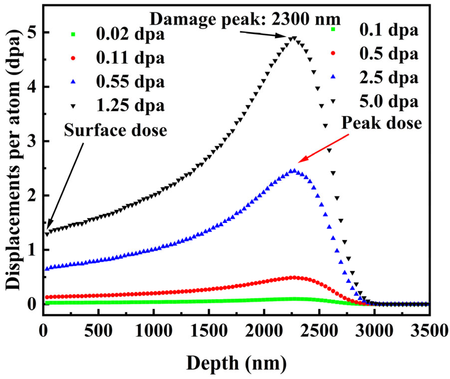
2.2. Ion Irradiation

The NSPG specimens were irradiated at room temperature with 7 MeV Xe26+ on the 320 kV Integrated Research Platform, Institute of Modern Physics, Chinese Academy of Science. Before performing the ion beam irradiation, information such as the deposition depth of the ion beam in the graphite sample and the irradiation damage distribution were determined by SRIM simulations [26]. As calculated by SRIM [27], the irradiation depth was approximately 2.9 µm. At a depth of approximately 2.3 µm, the irradiation damage reached a maximum. The damage level (displacement per atom, dpa) was calculated by d p a = N d i s p l a c e m e n t N a t o m = Φ n d i s p l a c e m e n t ρ a t o m , where Φ, ndisplacement, and ρatom are, respectively, the ion fluence, the number of displacements/ion/unit depth, and the atomic density [28]. Table 1 shows the fluences and corresponding irradiation damage level of the ion irradiation experiments. Figure 1 gives the depth profile of displacement per atom induced by 7 MeV Xe26+ ion irradiation in graphite as simulated with SRIM.

2.3. Characterization Methodology

The information of the pore structure of NSPG was obtained by automatic mercury porosimeter (AutoPore IV 9500, Germany) as follows: The porosity is the ratio of the volume of measurable pores and voids in a solid to the total volume occupied by the solid. Mercury porosimetry is also based on this principle [29]: Φ = V 1 V 2 . The V1 and V2 in the equation are the volume of mercury pressed at low and high pressures and the volume of the sample, respectively. V1 was measured directly in the low- and high-pressure experiments, most critically to obtain the sample volume V2. The details are as follows [29]: V 2 = W 4 W 3 W 2 W 1 ρ H g . W1, W2, W3, and W4 are the mass of the blank sample tube, the total mass of the blank sample tube and the sample, the total mass of the blank tube, sample and injected mercury at a certain pressure, the total mass of the blank sample tube, and the mercury that filled the blank sample tube, respectively. The bulk density is the weight per unit volume in the natural state (including the solid material together with its open and closed pores). It can be calculated from the following formula: ρ 0 = M V 0 . The M and V0 in the equation are the quality of the material and the volume of the material, respectively. It can also be calculated using the volume of mercury discharged from the sample at the minimum mercury filling pressure. The results of the two calculations are about the same. The pore diameter can be obtained from the Washburn equation by means of the applied pressure [30]: δ = 4 γ cos θ P . The δ, γ, P, and θ are the pore diameter, the surface tension of mercury (0.485 N/m), the pressure and contact angle between mercury and the pore surface (130°), respectively [30]. However, mercury porosimetry has certain limitations in that it assumes that all the pores of graphite are cylindrical. In addition, when the applied pressure exceeds approximately 18.2 MPa, the pores of the graphite internals may be locally deformed or damaged, resulting in high measured porosity [31]. Despite this, mercury porosimetry is still widely used for the measurement of the pore size of graphite.
The changes in the morphological structure of the graphite samples were monitored by scanning electron microscopy (SEM) (LEO 1530VP, Germany). Samples were scanned along graphite surface vertically in secondary electron mode (SE2) at an accelerating voltage of 5 kV. Morphological changes at the same location of the samples were monitored and observed comparatively before and after irradiation to reveal the effect of irradiation on the samples.
To quantify the irradiation-induced changes in the micromorphology and structure of the surface of NSPG, the samples were analyzed by atomic force microscopy (AFM) (Bruker Multimode 8) before and after irradiation. The imaging mode was selected to be non-contact, the scanning resolution was 512 pixels × 512 pixels, and post-processing of the data was accomplished with the help of NanoScope Analysis.
The grazing incidence XRD (GIXRD, Germany) was carried out by a Bruker D8 Advance powder X-ray diffraction (XRD) utilizing a CuKα1 radiation source (λ = 1.5406 Å) conditioned by two 2.5° Soller slits and a 0.025 mm Ni mask. The reflected X-ray intensity was continuously measured and recorded with a LynxEye XE counter during θ~2θ scans, which were conducted within the range of 20~70° (2θ), under a tube power setting of 40 kV/40 mA. These scans were performed using 0.02° (2θ) steps separated by 0.15 s. To reduce the influence of the unirradiated areas of the samples, the incidence angle was adjusted to 0.2°.
A Raman spectrometer (Horiba Jobin-Yvon LabRam HR800, French) was used to characterize the defects induced by irradiation. In this study, an excitation wavelength of 532.0 nm and a grating of 600 gr/mm were used. The effective depth of penetration was about 50.0 nm.

3. Results and Discussion

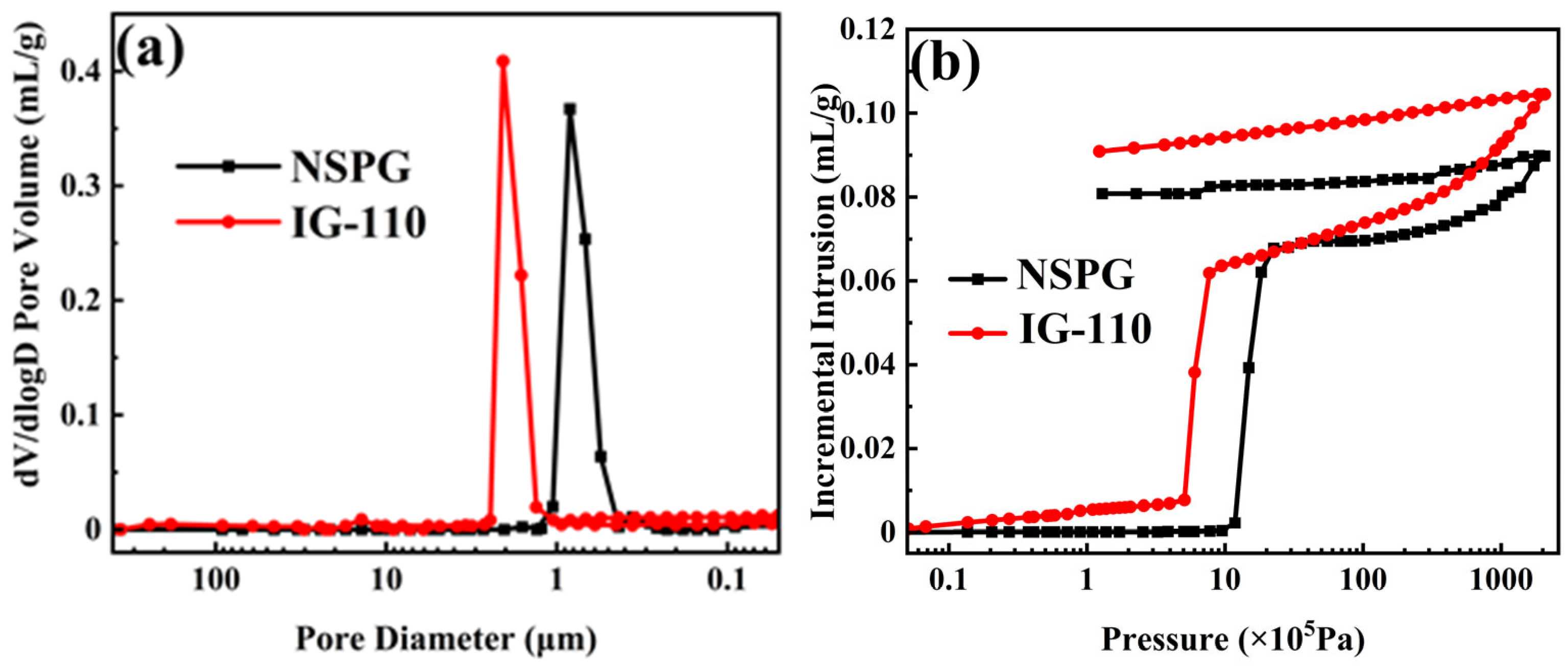
3.1. Pore Structure Analysis

Figure 2 shows the pore size distribution and the relationship between mercury injection and pressure for NSPG and IG-110. Table 2 provides the properties of the two types of graphite. The density of NSPG was 1.79 g/cm3 and its open porosity was 15.9%, while the density and open porosity of IG-110 were, respectively, 1.77 g/cm3 and 18.4% [17]. In addition, the median pore diameter of NSPG was 0.802 μm, which is significantly smaller than IG-110’s 1.84 μm. Figure 2b shows a step-by-step process of the incremental injection of mercury into the graphite. For the first-stage pressure (0~5.09 × 10⁵ Pa) of IG-110, only a small amount of mercury penetrates into the graphite. With pressure increase, mercury injection starts to increase sharply at the second stage from 5.09 × 10⁵ Pa to 1.99 × 10⁷ Pa and then tends to saturate. When the pressure is greater than 1.99 × 10⁷ Pa, the amount of mercury injected increases further, which may be the result of the mechanical breaking of the closed cell. The mercury injection process of NSPG can also be similarly divided into three of such stages. The differences between the two types of graphite are primarily in the trigger and saturation pressures that are caused by the pore size. Since NSPG has a relatively small pore structure that will generate high-interface capacitive forces, the first Hg permeation stage will slowly continue up to 1.18 × 10⁶ Pa. In addition, because NSPG has a lower open porosity, the total amount of mercury ultimately injected (0.0898 mL/g) is much lower than that of IG-110 (0.1045 mL/g). Previous studies have indicated that both molten salts and mercury have poor wettability to graphite, which makes the penetration of molten salts into graphite comparable to the penetration of mercury into graphite [32]. The results show that IG-110 cannot prevent molten salt penetration, while NSPG can satisfy the pore size requirements of MSRs.

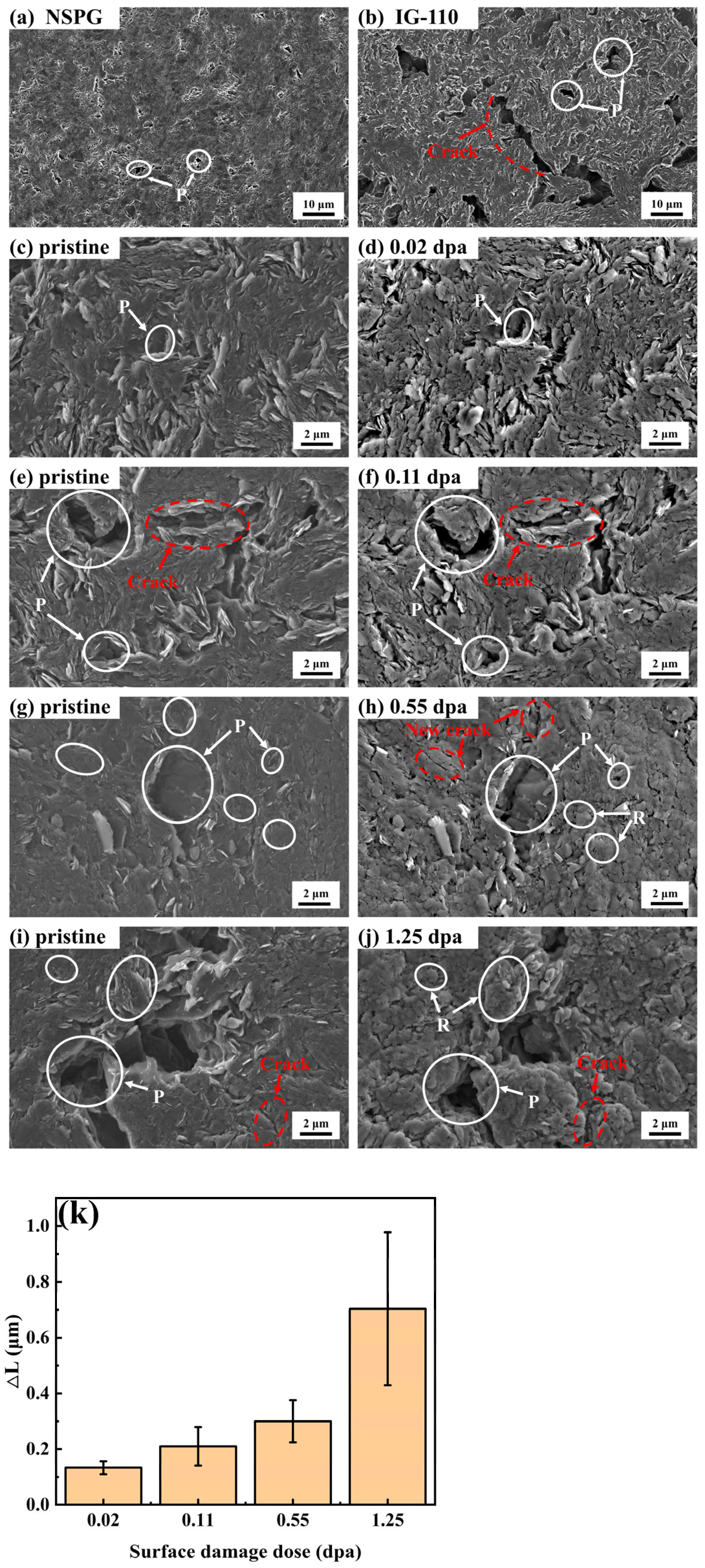
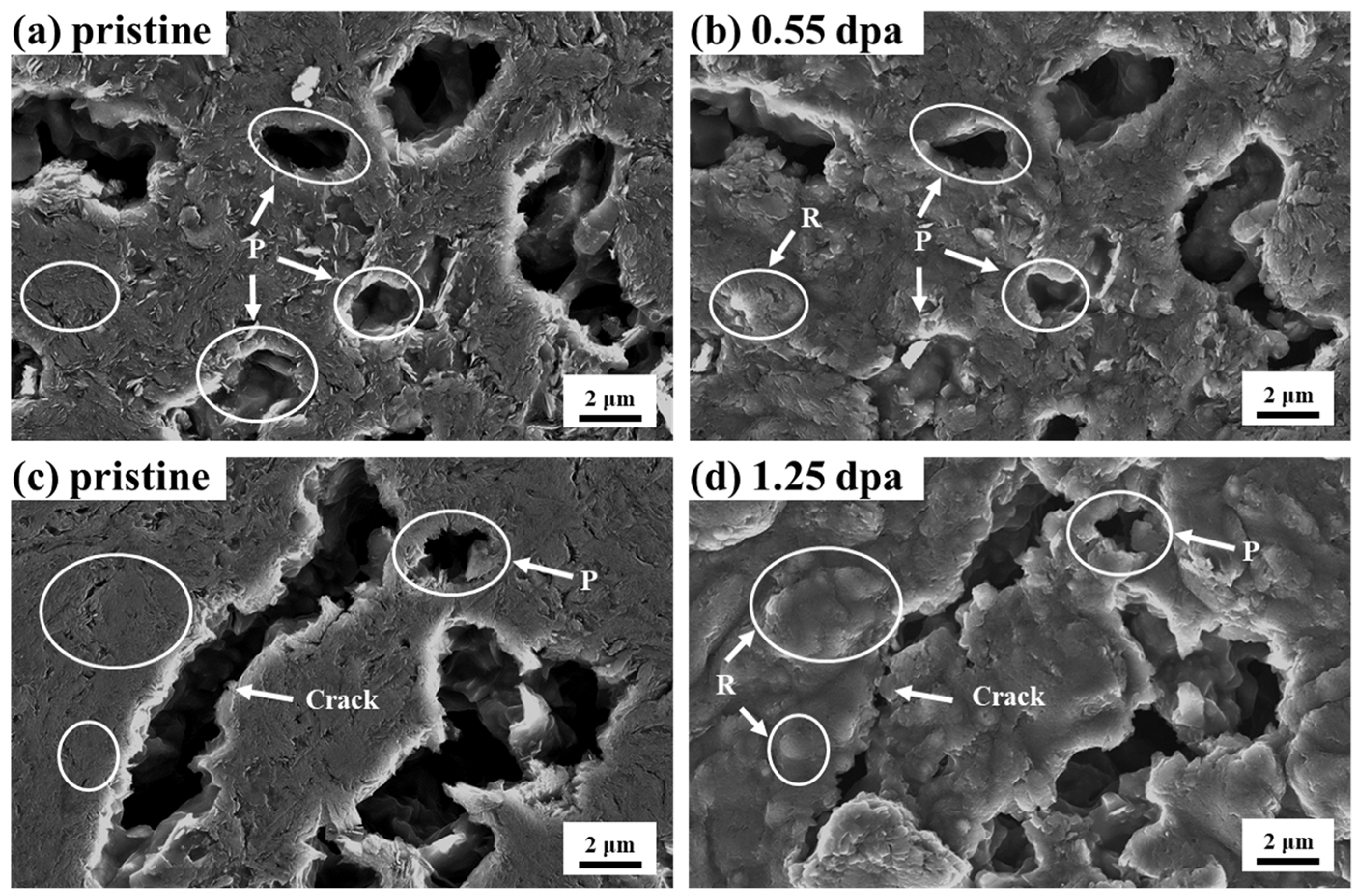
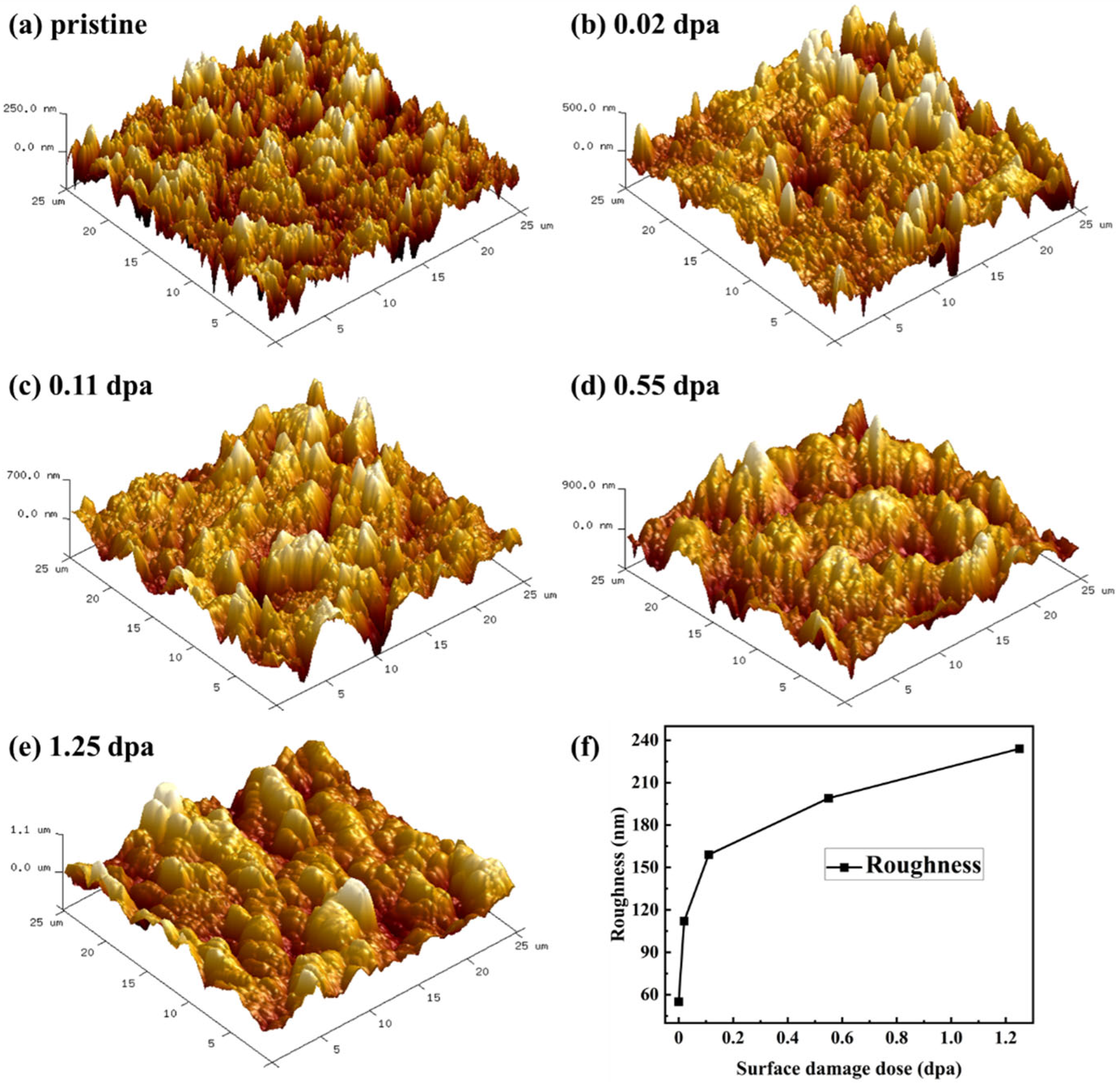
3.2. Morphology Variation

The SEM images of NSPG and IG-110 are shown in Figure 3a,b. The graphite before irradiation shows the typical surface morphology after the polishing of polycrystalline graphite. Specifically, IG-110 has many pores and a fine graphite microcrystalline structure. The shape of these pores is irregular, and the distribution of pore size is wide, with the size ranging from a few μm to tens of μm. In contrast, the surface of the NSPG is relatively smooth, with fewer and smaller pores. The edges and interiors of the pores of NSPG are smooth and flat, and there are almost no significant cracks. This is in agreement with the results of the mercury injection penetration test, which indicate that although NSPG is not subjected to an impregnation process, the smaller pore structure can still satisfy the infiltration requirements of graphite for molten salt reactors.
After different doses of Xe ion irradiation at room temperature, significant changes in the morphology of the surface of NSPG could be observed in the SEM images shown in Figure 3c–j. As the irradiation dose increases, the flatness of the graphite surface gradually deteriorates (Figure 3d,f,h,i). After the irradiation dose is lowered (0.02~0.11 dpa), the wrinkles on the graphite surface are more distinct and the surface becomes rough, which is associated with the irradiation-induced c-axis swelling [23]. This is because the incident Xe ions bombard carbon atoms from graphite lattice nodes during irradiation, generating a large number of interstitial atoms and vacancies. The accumulation of interstitial atoms between the two basal planes as well as the growth of incomplete planes result in the formation of additional basal planes and interstitial rings, which result in the expansion of graphite microcrystals along the c-axis direction. The pores of graphite show the phenomenon of squeezing and contracting after irradiation with the low dose of irradiation. The average pore size on the surface of graphite is reduced. Figure 3k shows the changes in the shrinkage (ΔL) of the pore size of the NSPG. The average ΔL increases with the surface irradiation damage dose, which indicates that the size of NSPG and crystallites increase and expand. However, the shrinkage of the pore size of NSPG is less than that of IG-110 under the same conditions, as shown in ref. [33]. This indicates that NSPG is not sensitive to irradiation. The shrinkage of the pores is due to the fact that the pores and microcracks of graphite have an accommodating effect on the swelling of the graphite microcrystals, but this accommodating effect has a limitation [23,34]. For example, under 0.11 dpa irradiation (Figure 3f), the pores of the graphite surface will tend to close when the accommodating effect of the graphite surface swelling reaches the saturation level. Previous studies have shown that the dimensional change of graphite is faster at irradiation temperatures below 250 °C, whereas in this paper, the irradiation is carried out at room temperature; thus, the amorphization of graphite is rapidly induced [34]. Heggie et al. pointed out that permanent basal plane nano-buckling may also lead to the expansion of the c-axis of graphite crystals at irradiation temperatures below 250 °C [35]. So, at a higher dose of irradiation (0.55 dpa), obvious bulging protrusions are produced on the surface of graphite, i.e., the “Ridge-like” structures (Figure 3h), which are mainly caused by the following: firstly, the increase in the degree of swelling induced by irradiation, and secondly, the pores of graphite reach saturation in the accommodation of swelling. It is noteworthy that after 0.55 dpa irradiation, the surface of NSPG also shows small cracks, which is due to the increased expansion of graphite microcrystals in the c-axis direction, leading to dimensional shrinkage in the a-axis direction. With the increase in the surface irradiation dose to 1.25 dpa, the surface morphology of NSPG changes greatly, and the increase in the size of the “ridge-like” structure and the growth of cracks are more obvious. The relative position of graphite flakes also shifts, and the boundary bending and deformation occur, which are similar to that of IG-110 (Figure 4d) [33]. This indicates that Xe ion bombardment has led to the destruction of the microstructure of the graphite surface, and the irradiation damage effect is more obvious. But compared with the traditional nuclear graphite IG-110 at the same irradiation dose (Figure 4b), the surface of NSPG is relatively intact with less change, which indicates that NSPG is insensitive to irradiation in terms of micromorphology. Additionally, in marked contrast to NSPG, the wrinkled surface of IG-110 becomes relatively smooth after irradiation, which may be related to the initial crystallinity of graphite. Previous studies have shown that this may be due to the improvement of crystal orientation of the disordered structure by irradiation-induced graphitization [33].
To visualize the irradiation-induced “ridge-like” structure, the AFM images of NSPG before and after irradiation are shown in Figure 5. The results show that the roughness of the sample surface increases rapidly after irradiation at doses of 0.02~0.11 dpa, resulting directly in more prominent wrinkles on the sample surface, which is consistent with the results observed in SEM images. The surface roughness of the samples continues to increase with the irradiation dose (Figure 5d,e), while the number and size of the “ridge-like” structures increase, resulting in larger protruding particles and the phenomenon of “bulging”. This is related to the accommodation of irradiation-induced swelling by the pores and cracks of graphite reaching saturation, resulting in a more pronounced increase in expansion in the vertical direction, so that the SEM observes a huge change in the morphology of samples.

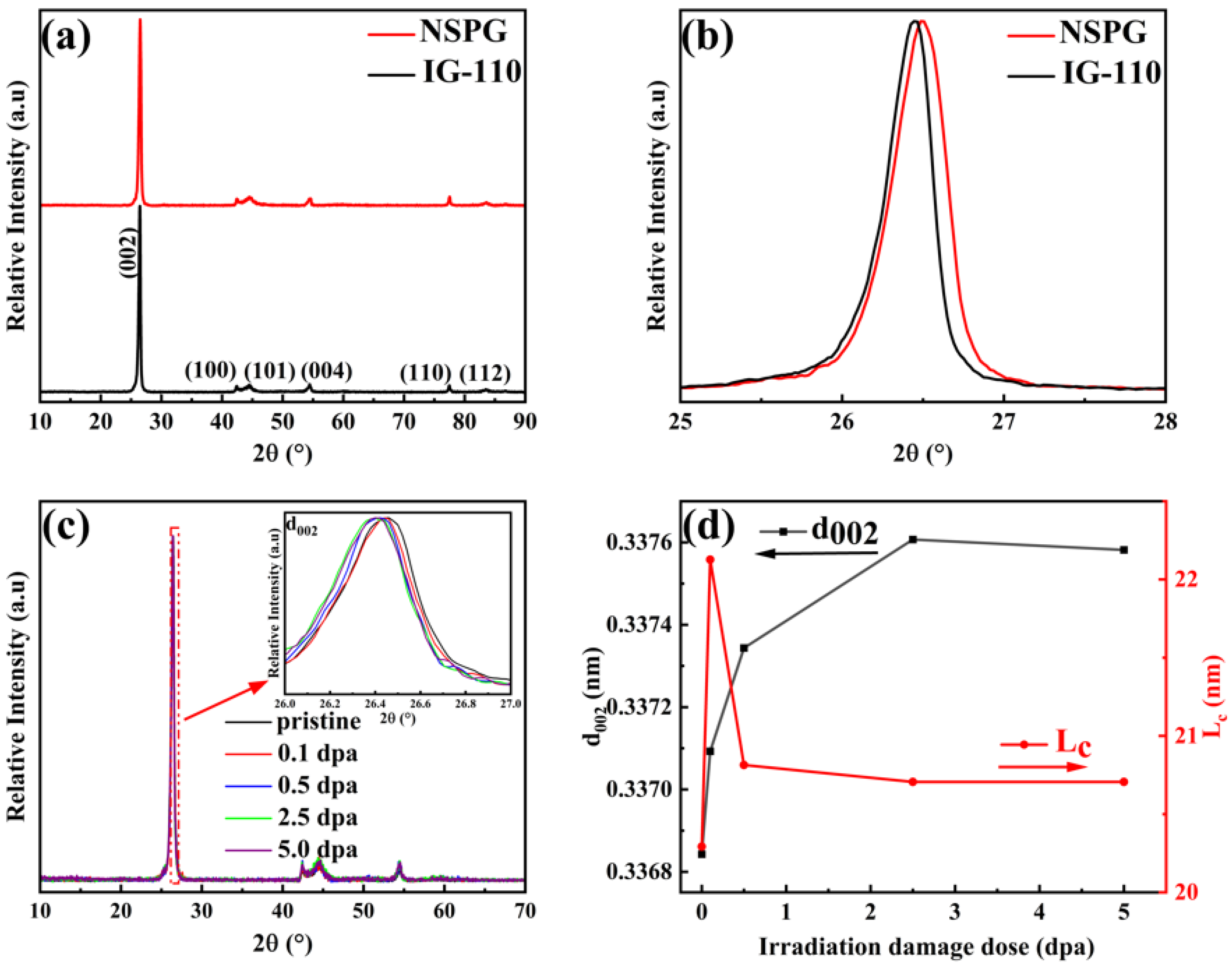
3.3. Structural Variation

The XRD patterns in Figure 6 show that the prepared NSPG and IG-110 have the same hexagonal structure (graphite-2H: hexagonal, space group P63/mmcP63/m2/m2/c). The (002) and (004) diffraction peaks in the figure are related to the graphitized structure of the materials, which indicate that both graphites have the ordered graphite structure. The Braggs diffraction angle of the (002) diffraction peak of NSPG is a little larger as compared to IG-110. The d002 (interlayer spacing), crystallite stacking height (Lc), and the graphitization degree (g) can be calculated by referring to the following equation [36]: d 002 = λ 2 s i n θ , g = 0.3440 d 002 0.3440 0.3354 , and L c = 0.89 λ β 002 c o s θ 002 , respectively. The β, θ, and λ in the equation are the FWHM, Bragg angle of the (002) diffraction peak, and the wavelength of X-ray, respectively [37]. As calculated, NSPG has a smaller layer spacing and higher graphitization, with a graphitization of 89.77%, which is larger than that of IG-110 at 83.60%, and this difference in the degree of initial graphitization will influence the irradiation behavior of the graphite. GIXRD patterns and (002) peaks of NSPG graphite before and after irradiation are shown in Figure 6c. Figure 6c shows clearly that the (002) diffraction peak of irradiated NSPG shifts to lower diffraction angles, which is similar to IG-110 [33]. This indicates an increase in d002 and a decrease in the graphitization degree of NSPG. The changing trend of d002 and crystallite stacking height (Lc) of NSPG after irradiation are presented in Figure 6d. The d002 of NSPG increased with increasing irradiation dose, reaching saturation at a dose of 2.5 dpa. The d002 of irradiated IG-110 reached saturation at a lower dose of 0.5 dpa under the same conditions in ref. [33]. This indicates that IG-110 is more sensitive to irradiation than NSPG. The Lc increased rapidly after irradiation at a dose of 0.1 dpa, but decreased at 0.5 dpa, and then stabilized with the dose; this trend of Lc is similar to that of the data from neutron-irradiated nuclear graphite [38]. These are caused by the displacement damage cascade resulting from irradiation, which produces a large number of point defects in the graphite, which further migrate and merge to develop into dislocations. The dislocations climb to generate new planes, which result in the expansion of the c-axis [39]. The decrease in Lc is related to the irradiation-induced disordered structure. Previous studies have indicated that with a further increase in irradiation dose, the strain during irradiation induces the bending of the basal plane, the fracture of the grain surface, and the fragmentation of the grains. The accumulation of defects produced by irradiation leads to the development of graphite toward amorphization [20]. The appearance of “ridge-like” structures can be considered as an intermediate stage in the amorphization of the surface of graphite [40]. The XRD results provide evidence for the SEM results that the irradiation-induced changes in the microstructure of graphite caused the morphology changes in Section 3.2.
Raman spectroscopy is a common technique for analyzing carbon materials such as graphite, carbon fibers, carbon nanotubes, and fullerenes. In the case of highly ordered graphitic materials, the G peak (near 1580 cm−1) is the intrinsic peak of graphite, which is Raman-active for sp2 hybridization [41]. The D peak (near1350 cm−1) represents the disorder of the graphitic structure, which is associated with vacancy defects, edge disorder, irregular C (sp3 bonds), etc. [42]. The changes in graphite grain size and disorder induced by irradiation can be indirectly obtained by analyzing certain parameters of the characteristic peaks, such as peak shape, intensity, full width at half maximum (FWHM), etc. The ID/IG intensity ratio is an important parameter to quantify the disorder, and it has been widely used to characterize the density of defects in graphite materials [43]. The grain size La can be calculated from the T-K empirical formula [44]: L a n m = 2.4 × 10 10 λ 4 ( I D I G ) 1 , where λ (nm) is the wavelength of the laser, which is 532 nm in this work, and this formula is valid for use in the range of La > 2 nm. Figure 7a,b are the Raman spectra of NSPG before and after irradiation, respectively. To further investigate the effect of irradiation dose on the microstructure of graphite, the Raman spectra of NSPG were fitted to the peaks according to the Lorentz principle and were divided into 1150, 1350, 1500, and 1580 cm−1, which are denoted as v1, D, G, and v3 peaks. The v1 peak is a mixed vibration of interlaced C-C and C-H bonds whose appearance indicates the emergence of nanocrystalline structures [45], and the v3 peak is caused by the stretching vibration of C=C, which embodies interplanar defects and is more sensitive to interstitial atom-shaped defects in graphite and amorphous carbon [46]. The insignificant intensity of the v1 and v3 peaks in unirradiated graphite indicates that only a few interstitial atomic-type defects existed in the graphite before irradiation and that the graphite possesses a highly ordered microcrystalline structure. The trends of Iv3/IG and ID/IG with irradiation dose before and after ion irradiation are shown in Figure 7f. Table 3 summarizes the changes in La with irradiation dose derived from Zhang’s study of IG-110 under the same conditions for comparison with the NSPG [20]. The results show that the Iv3/IG increases and then slowly decreases with irradiation dose after irradiation, which indicates that a large number of interstitial atoms are formed at the beginning of irradiation, and then the compounding of the interstitial atoms and vacancies may have occurred afterward. After irradiation at a dose of 0.1 dpa, the relative intensity as well as the FWHM of the D peak increased significantly, indicating that the irradiation led to a rapid increase in the defect density of the graphite. It is worth noting that the characteristic peaks of the graphite (D and G peaks) are still distinguishable at this dose. Previous research results on IG-110 under the same irradiation conditions have shown that the characteristic peaks of IG-110 are no longer distinguishable at this dose [33]. The magnitude of the change in ID/IG is also small compared to that of IG-110, with the decrease in La from ~32 nm for the pre-irradiated to ~19 nm. This indicates that the defect density of NSPG increases relatively slowly and is insensitive to irradiation, the laminar structure of NSPG after irradiation remains within the scale of a dozen nanometers, and the microcrystalline graphite is decomposed into nanocrystalline graphite. As the irradiation dose was increased to 2.5 dpa and 5.0 dpa, the D and G peaks began merging due to broadening, while the size of La decreased from ~12 nm to ~9 nm (see Table 3). This was attributed to the rapid growth of defects that severely damaged the graphite base layer, leading to bending and deformation of the basal plane. As a result, the nanocrystalline graphite gradually transitioned toward amorphization, aligning with the conclusions drawn from GIXRD. Raman spectroscopy further corroborates this by providing evidence of lattice defects.

4. Conclusions

In summary, the NSPG prepared by the “no impregnation” process can reduce the pore size of graphite to ~800 nm, which can meet the requirement of molten salt reactors. NSPG was screened using ion beam irradiation to simulate neutron irradiation. The results show that the graphitization degree of NSPG was better than IG-110. Under low-dose ion irradiation (<2.5 dpa), NSPG is insensitive to irradiation compared to IG-110, with smaller changes in the microstructure. The microstructural changes can be explained by the XRD results, which indicate that the increasing interlayer spacing of graphite after irradiation causes the shrinkage and closure of micropores on the surface of graphite. The changes in Lc, first increasing and then decreasing, are related to the irradiation-induced disordered structure, leading to the appearance of a “ridge-like” structure. Raman spectroscopy results show that the defect density of NSPG increases relatively slowly, and that the laminar structure of graphite remains within the scale of a few dozen nanometers after irradiation at doses (<2.5 dpa). As the irradiation dose increased, the accumulation of defects resulted in the graphite developing toward amorphization, which is consistent with the case of IG-110. The research reveals NSPG is less sensitive to irradiation than IG-110 under ion implantation at room temperature, which provides theoretical support for the application of NSPG in molten salt reactors. But its performance and behavior may be different at neutron irradiation and higher irradiation temperatures, and should be subject to the next step of neutron irradiation screening.

Author Contributions

Conceptualization, J.S.; Methodology, J.S. and H.H.; Software, P.L. (Pengfei Lian); Formal analysis, P.L. (Pengfei Lian) and P.L. (Pengda Li); Investigation, P.L. (Pengfei Lian); Resources, P.L. (Pengfei Lian); Writing—original draft, P.L. (Pengfei Lian) and P.L. (Pengda Li); Writing—review & editing, P.L. (Pengfei Lian); Visualization, P.L. (Pengfei Lian); Supervision, J.S., H.H., Z.T. and Z.L.; Project administration, J.S.; Funding acquisition, J.S., Z.T. and Z.L. All authors have read and agreed to the published version of the manuscript.

Funding

This research was funded by the National Natural Science Foundation of China (No. 52072397); Institute of Coal Chemistry, Chinese Academy of Sciences (No. SCJC-XCL202209); DNL Cooperation Fund, CAS (DNL202012).

Data Availability Statement

The raw/processed data required to reproduce these findings cannot be shared at this time as the data also forms part of an ongoing study.

Acknowledgments

This work was financially supported by the National Natural Science Foundation of China (No. 52072397); Institute of Coal Chemistry, Chinese Academy of Sciences (No. SCJC-XCL202209); DNL Cooperation Fund, CAS (DNL202012).

Conflicts of Interest

The authors declare no conflict of interest.

References

  1. Serp, J.; Allibert, M.; Beneš, O.; Delpech, S.; Feynberg, O.; Ghetta, V.; Heuer, D.; Holcomb, D.; Ignatiev, V.; Kloosterman, J.L.; et al. The molten salt reactor (MSR) in generation IV: Overview and perspectives. Prog. Nucl. Energy 2014, 77, 308–319. [Google Scholar] [CrossRef]
  2. Abram, T.; Ion, S. Generation-IV nuclear power: A review of the state of the science. Energy Policy 2008, 36, 4323–4330. [Google Scholar] [CrossRef]
  3. McCoy, H.E.; Beatty, R.L.; Cook, W.H.; Gehlbach, R.E.; Kennedy, C.R.; Koger, J.W.; Litman, A.P.; Sessions, C.E.; Weir, J.R. New Developments in Materials for Molten-Salt Reactors. Nucl. Appl. Technol. 1970, 8, 156–169. [Google Scholar] [CrossRef]
  4. Haubenreich, P.N.; Engel, J.R. Experience with the Molten-Salt Reactor Experiment. Nucl. Appl. Technol. 1970, 8, 118–136. [Google Scholar]
  5. Rosenthal, M.W.; Haubenreich, P.N.; Briggs, R.B. The Development Status of Molten-Salt Breeder Reactors; Oak Ridge National Laboratory: Oak Ridge, TN, USA, 1972. [Google Scholar]
  6. Campbell, A.A.; Burchell, T.D. Radiation Effects in Graphite. In Comprehensive Nuclear Materials; Elsevier: Oxford, UK, 2020; pp. 398–436. [Google Scholar] [CrossRef]
  7. He, X.J.; Song, J.L.; Tan, J.; Zhang, B.L.; Xia, H.H.; He, Z.T.; Zhou, X.T.; Zhao, M.W.; Liu, X.D.; Xu, L.; et al. SiC coating: An alternative for the protection of nuclear graphite from liquid fluoride salt. J. Nucl. Mater. 2014, 448, 1–3. [Google Scholar] [CrossRef]
  8. Bernardet, V.; Gomes, S.; Delpeux, S.; Dubois, M.; Guérin, K.; Avignant, D.; Renaudin, G.; Duclaux, L. Protection of nuclear graphite toward fluoride molten salt by glassy carbon deposit. J. Nucl. Mater. 2009, 384, 292–302. [Google Scholar] [CrossRef]
  9. Lee, J.J.; Arregui-Mena, J.D.; Contescu, C.I.; Burchell, T.D.; Katoh, Y.; Loyalka, S.K. Protection of graphite from salt and gas permeation in molten salt reactors. J. Nucl. Mater. 2020, 534, 152119. [Google Scholar] [CrossRef]
  10. Kasten, P.R.; Bettis, E.S.; Cook, W.H.; Eatherly, W.P.; Holmes, D.K.; Kedl, R.J.; Kennedy, C.R.; Kirslis, S.S.; McCoy, H.E.J.; Perry, A.M.; et al. Graphite behavior and its effects on MSBR performance. Nucl. Eng. Des. 1969, 9, 157–195. [Google Scholar] [CrossRef]
  11. He, Z.; Lian, P.F.; Song, Y.; Liu, Z.J.; Song, J.L.; Zhang, J.P.; Feng, J.; Yan, X.; Guo, Q.G. Improving molten fluoride salt and Xe135 barrier property of nuclear graphite by phenolic resin impregnation process. J. Nucl. Mater. 2018, 499, 79–87. [Google Scholar] [CrossRef]
  12. Zhang, J.C.; Shi, J.L.; Zhao, Y.; Guo, Q.G.; Liu, L.; Feng, Z.H.; Fan, Z. Structural changes in four different precursors with heat treatment at high temperature and resin carbon structural model. J. Mater. Sci. 2012, 47, 5891–5899. [Google Scholar] [CrossRef]
  13. Zhao, H.C.; He, Z.; Liu, Z.J.; Song, J.L.; Tsang, D.K.L.; Zhang, H.Y. Self-sintered nanopore-isotropic graphite derived from green pitch coke for application in molten salt nuclear reactor. Ann. Nucl. Energy 2019, 131, 412–416. [Google Scholar] [CrossRef]
  14. Song, J.L.; Zhao, Y.L.; Zhang, J.P.; He, X.J.; Zhang, B.L.; Lian, P.F.; Liu, Z.J.; Zhang, D.S.; He, Z.T.; Gao, L.N.; et al. Preparation of binderless nanopore-isotropic graphite for inhibiting the liquid fluoride salt and Xe135 penetration for molten salt nuclear reactor. Carbon 2014, 79, 36–45. [Google Scholar] [CrossRef]
  15. Wang, T.; Li, H.; Shen, Q.; Li, K.; Li, W.; Song, Q.; Zhang, S. Dependence of mechanical properties on microstructure of high-textured pyrocarbon prepared via isothermal and thermal gradient chemical vapor infiltration. Compos. Part B Eng. 2020, 192, 107982. [Google Scholar] [CrossRef]
  16. Zhang, H.Y.; Cheng, J.X.; Lian, P.F.; He, Z.; Wang, Q.; Yu, A.; Song, J.L.; Tang, Z.F.; Liu, Z.J. Effects of irradiation on nano-pore phenol-formaldehyde resin infiltrated IG-110 graphite. Nucl. Mater. Energy 2022, 32, 101215. [Google Scholar] [CrossRef]
  17. Zhang, H.Y.; Lei, Q.T.; Song, J.L.; Liu, M.; Zhang, C.; Gao, Y.T.; Zhang, W.T.; Xia, H.H.; Liu, X.D. Direct characterization of ion implanted nanopore pyrolytic graphite coatings for molten salt nuclear reactors. RSC Adv. 2018, 8, 33927–33938. [Google Scholar] [CrossRef]
  18. Song, Y.Z.; Zhai, G.T.; Li, G.S.; Shi, J.L.; Guo, Q.G.; Liu, L. Carbon/graphite seal materials prepared from mesocarbon microbeads. Carbon 2004, 42, 1427–1433. [Google Scholar] [CrossRef]
  19. Zhou, S.; Xia, J.; Yan, L. Binderless Carbon/Graphite Materials. J. Mater. Sci. Technol. 1997, 13, 184–188. [Google Scholar]
  20. Zhang, H.Y.; Song, J.L.; Tang, Z.F.; Liu, Z.J.; Liu, X.D. The surface topography and microstructure change of densified nanopore nuclear graphite impregnated with polyimide and irradiated by xenon ions. Appl. Surf. Sci. 2020, 531, 147408. [Google Scholar] [CrossRef]
  21. Ragan, S.A.; Marsh, H. Science and technology of graphite manufacture. J. Mater. Sci. 1983, 18, 3161–3176. [Google Scholar] [CrossRef]
  22. Galy, N.; Toulhoat, N.; Moncoffre, N.; Pipon, Y.; Bérerd, N.; Ammar, M.R.; Simon, P.; Deldicque, D.; Sainsot, P. Ion irradiation used as surrogate of neutron irradiation in graphite: Consequences on 14C and 36Cl behavior and structural evolution. J. Nucl. Mater. 2018, 502, 20–29. [Google Scholar] [CrossRef]
  23. Huang, Q.; Li, J.J.; Liu, R.D.; Yan, L.; Huang, H.F. Surface morphology and microstructure evolution of IG-110 graphite after xenon ion irradiation and subsequent annealing. J. Nucl. Mater. 2017, 491, 213–220. [Google Scholar] [CrossRef]
  24. Zhou, X.W.; Yang, Y.; Song, J.; Lu, Z.M.; Zhang, J.; Liu, B.; Tang, Y.P. Carbon materials in a high temperature gas-cooled reactor pebble-bed module. New Carbon Mater. 2018, 33, 97–108. [Google Scholar] [CrossRef]
  25. Sun, X.M.; Dong, Y.J.; Zhou, Y.P.; Li, Z.C.; Shi, L.; Sun, Y.L.; Zhang, Z.Y. Effects of reaction temperature and inlet oxidizing gas flow rate on IG-110 graphite oxidation used in HTR-PM. J. Nucl. Sci. Technol. 2017, 54, 196–204. [Google Scholar] [CrossRef]
  26. Stoller, R.E.; Toloczko, M.B.; Was, G.S.; Certain, A.G.; Dwaraknath, S.; Garner, F.A. On the use of SRIM for computing radiation damage exposure. Nucl. Instrum. Methods Phys. Res. Sect. B-Beam Interact. Mater. Atoms 2013, 310, 75–80. [Google Scholar] [CrossRef]
  27. Zubair, M.; Hazem, R.; Ahmad, I.; Khan, M.I.; Zhao, T.-K.; Ali, H.; Ali, T.; Arshad, M.; Rehman, F.; Ahmad, P.; et al. The effects of 5 MeV carbon ion irradiation on micro-fine grain graphite. Radiat. Phys. Chem. 2020, 166, 108512. [Google Scholar] [CrossRef]
  28. Zhang, B.L.; Xia, H.H.; He, X.J.; He, Z.T.; Liu, X.D.; Zhao, M.W.; Zhou, X.T. Characterization of the effects of 3-MeV proton irradiation on fine-grained isotropic nuclear graphite. Carbon 2014, 77, 311–318. [Google Scholar] [CrossRef]
  29. Dickinson, J.M.; Shore, J.W. Observations concerning the determination of porosities in graphites. Carbon 1968, 6, 937–941. [Google Scholar] [CrossRef]
  30. Washburn, E.W. The dynamics of capillary flow. Phys. Rev. 1921, 17, 273–283. [Google Scholar] [CrossRef]
  31. Arregui-Mena, J.D.; Worth, R.N.; Bodel, W.; März, B.; Li, W.; Campbell, A.A.; Cakmak, E.; Gallego, N.; Contescu, C.; Edmondson, P.D. Multiscale characterization and comparison of historical and modern nuclear graphite grades. Mater. Charact. 2022, 190, 112047. [Google Scholar] [CrossRef]
  32. He, Z.T.; Gao, L.N.; Qi, W.; Zhang, B.L.; Wang, X.; Song, J.L.; He, X.J.; Zhang, C.; Tang, H.; Holmes, R.; et al. Molten FLiNaK salt infiltration into degassed nuclear graphite under inert gas pressure. Carbon 2015, 84, 511–518. [Google Scholar] [CrossRef]
  33. Zhang, H.Y.; Cheng, J.X.; Song, J.L.; Yin, H.Q.; Tang, Z.F.; Liu, Z.J.; Liu, X.D. Topography changes and microstructural evolution of nuclear graphite (IG-110) induced by Xe26+ irradiation. New Carbon Mater. 2023, 38, 393–402. [Google Scholar] [CrossRef]
  34. Jiang, M.; Ammigan, K.; Lolov, G.; Pellemoine, F.; Liu, D. Porosity evolution in proton irradiated microfine-grained POCO graphite. J. Nucl. Mater. 2023, 587, 154732. [Google Scholar] [CrossRef]
  35. Heggie, M.I.; Suarez-Martinez, I.; Davidson, C.; Haffenden, G. Buckle, ruck and tuck: A proposed new model for the response of graphite to neutron irradiation. J. Nucl. Mater. 2011, 413, 150–155. [Google Scholar] [CrossRef]
  36. Manoj, B. Investigation of nanocrystalline structure in selected carbonaceous materials. Int. J. Miner. Metall. Mater. 2014, 21, 940–946. [Google Scholar] [CrossRef]
  37. Manoj, B.; Kunjomana, A.G. Study of Stacking Structure of Amorphous Carbon by X-Ray Diffraction Technique. Int. J. Electrochem. Sci. 2012, 7, 3127–3134. [Google Scholar] [CrossRef]
  38. Zhou, Z.; Bouwman, W.G.; Schut, H.; van Staveren, T.O.; Heijna, M.C.R.; Pappas, C. Influence of neutron irradiation on the microstructure of nuclear graphite: An X-ray diffraction study. J. Nucl. Mater. 2017, 487, 323–330. [Google Scholar] [CrossRef]
  39. Asthana, A.; Matsui, Y.; Yasuda, M.; Kimoto, K.; Iwata, T.; Ohshima, K.-I. Investigations on the structural disordering of neutron-irradiated highly oriented pyrolytic graphite by X-ray diffraction and electron microscopy. J. Appl. Crystallogr. 2005, 38, 361–367. [Google Scholar] [CrossRef]
  40. Dai, Z.B.; Cao, X.L.; Xu, K.; Shen, K. Research progress on irradiation defects and crystal size change of graphite crystal. Carbon Tech. 2022, 41. [Google Scholar] [CrossRef]
  41. Cançado, L.G.; Takai, K.; Enoki, T.; Endo, M.; Kim, Y.A.; Mizusaki, H.; Speziali, N.L.; Jorio, A.; Pimenta, M.A. Measuring the degree of stacking order in graphite by Raman spectroscopy. Carbon 2008, 46, 272–275. [Google Scholar] [CrossRef]
  42. Mathew, S.; Chan, T.K.; Zhan, D.; Gopinadhan, K.; Barman, A.R.; Breese, M.B.H.; Dhar, S.; Shen, Z.X.; Venkatesan, T.; Thong, J.T.L. The effect of layer number and substrate on the stability of graphene under MeV proton beam irradiation. Carbon 2011, 49, 1720–1726. [Google Scholar] [CrossRef]
  43. Jiang, M.; Ammigan, K.; Lolov, G.; Pellemoine, F.; Liu, D. A novel method for quantifying irradiation damage in nuclear graphite using Raman spectroscopy. Carbon 2023, 213, 118181. [Google Scholar] [CrossRef]
  44. Tuinstra, F.; Koenig, J.L. Raman Spectrum of Graphite. J. Chem. Phys. 1970, 53, 1126–1130. [Google Scholar] [CrossRef]
  45. Ferrari, A.C.; Robertson, J. Origin of the 1150 cm−1 Raman mode in nanocrystalline diamond. Phys. Rev. B 2001, 63, 121405. [Google Scholar] [CrossRef]
  46. Ferrari, A.C.; Robertson, J. Resonant Raman spectroscopy of disordered, amorphous, and diamondlike carbon. Phys. Rev. B 2001, 64, 075414. [Google Scholar] [CrossRef]
Figure 1. Depth profile of displacement per atom induced by 7 MeV Xe26+ ion irradiation in graphite as simulated with SRIM.
Carbon 10 00050 g001
Figure 2. The pore size distribution (a) and the relationship between mercury injection and pressure for NSPG and IG-110 (b).
Carbon 10 00050 g002
Figure 3. SEM images of NSPG (a,c,e,g,i) and IG-110 (b) before and after irradiation at a surface damage dose of 0.02 dpa (d), 0.11 dpa (f), 0.55 dpa (h), and 1.25dpa (j) (P and R refer to pores and ridge-like structures, respectively). (k) Changes in the shrinkage (ΔL) of the pore size with irradiation dose.
Carbon 10 00050 g003
Figure 4. SEM images of IG-110 (a,c) and after irradiation at a surface damage dose of 0.55 dpa (b) and 1.25 dpa (d) [33].
Carbon 10 00050 g004
Figure 5. AFM images of NSPG before (a) and after irradiation at surface damage doses of (b) 0.02 dpa, (c) 0.11 dpa, (d) 0.55 dpa, and (e) 1.25 dpa. (f) The roughness of NSPG varies with the dose of surface damage.
Carbon 10 00050 g005
Figure 6. XRD patterns (a,b) of NSPG and IG-110; (c) GIXRD patterns of NSPG before and after irradiation. (The arrow is pointing to the localized zoomed-in image.); (d) d002 and Lc as functions of irradiation dose.
Carbon 10 00050 g006
Figure 7. Raman spectra of NSPG (a) before and (be) after irradiation; (f) ID/IG and Iv3/IG as functions of irradiation dose.
Carbon 10 00050 g007
Table 1. Fluences and corresponding irradiation damage doses of ion irradiation experiments of NSPG.
Fluence (Ions/cm2)Peak Irradiation Dose (dpa)Surface Irradiation Dose (dpa)
9.6 × 10130.10.02
4.8 × 10140.50.11
2.4 × 10152.50.55
4.8 × 10155.01.25
Table 2. Properties of NSPG and IG-110 [14] graphite.
PropertiesIG-110NSPG
Bulk density (g/cm3)1.77 ± 0.021.79 ± 0.02
Open porosity (%)18.4 ± 0.115.9 ± 0.1
Median pore diameter (volume, μm)1.8400.802
Flexure strength (MPa)39.2 ± 2.561.0 ± 2.5
Compressive strength (MPa)78 ± 3102 ± 3
Thermal conductivity (W/m·K)116 ± 2127 ± 2
CTEs (25–300 °C, 10−6/K)4.5 ± 0.24.1 ± 0.2
Table 3. Changes in La in NSPG and IG-110 [20] before and after ion irradiation.
GraphiteNSPG/IG-110
Irradiation damage dose (dpa)00.10.52.55.0
Crystallite lateral size La (nm)31.516/24.97618.664/8.33911.581/7.6339.423/7.5429.111/7.267
Disclaimer/Publisher’s Note: The statements, opinions and data contained in all publications are solely those of the individual author(s) and contributor(s) and not of MDPI and/or the editor(s). MDPI and/or the editor(s) disclaim responsibility for any injury to people or property resulting from any ideas, methods, instructions or products referred to in the content.

