
Piezoresistive Response of Carbon Nanotube Yarn Monofilament Composites under Axial Compression


Abstract
:1. Introduction
2. Materials, Fabrication and Characterization
2.1. Materials
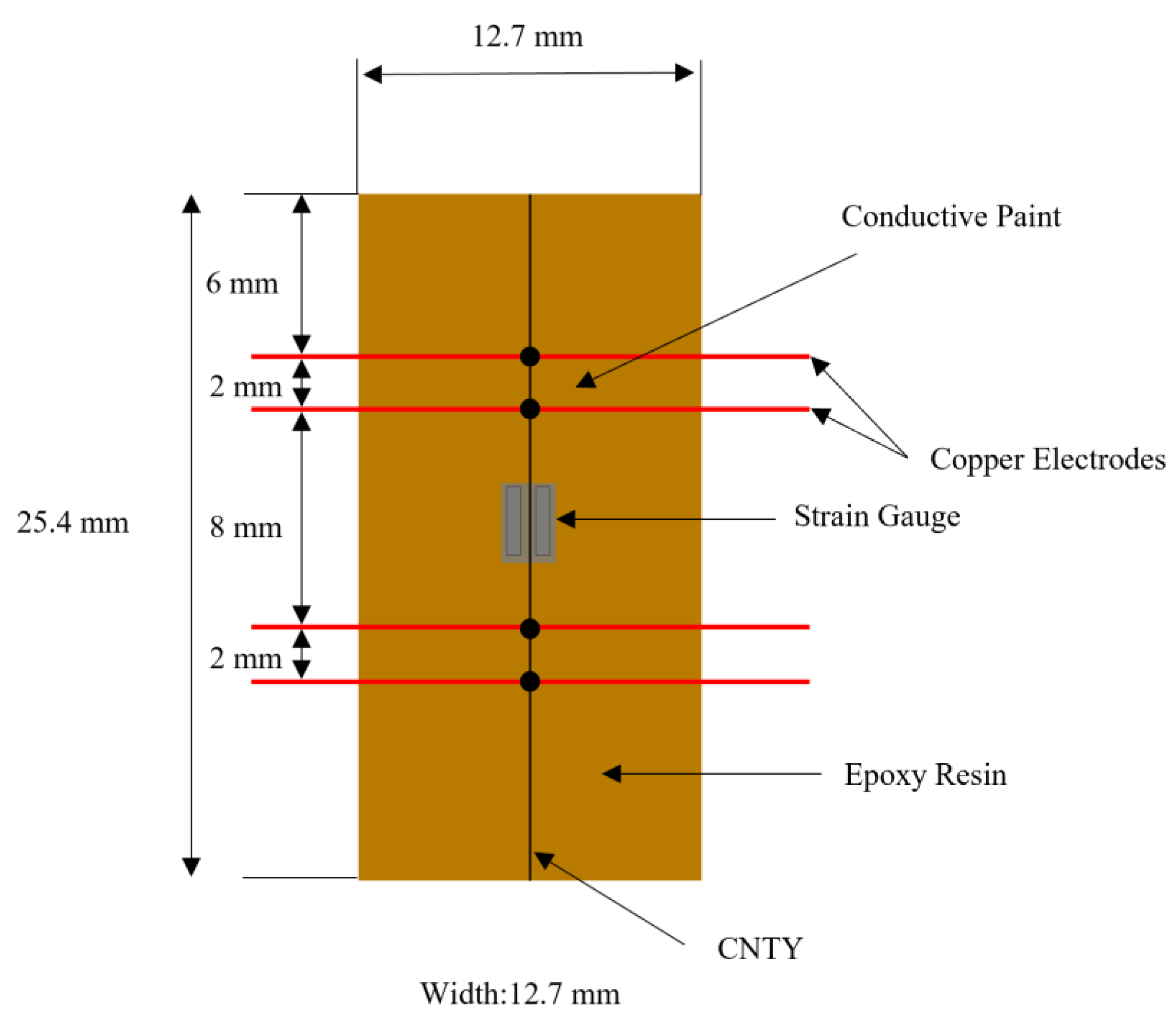
2.2. Fabrication
2.3. Electrical and Mechanical Measurements
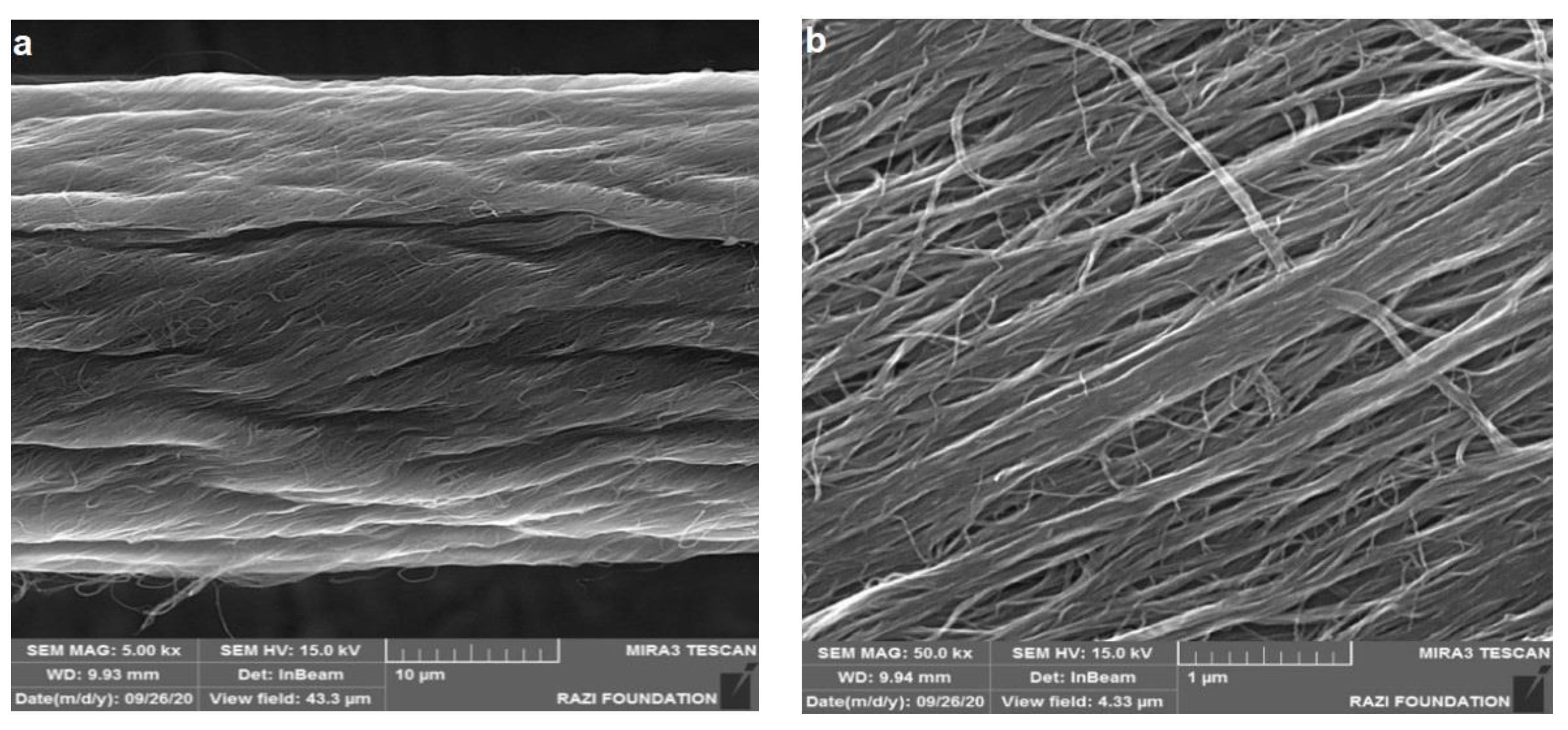
2.4. Scanning Electron Microscopy
3. Results and Discussion
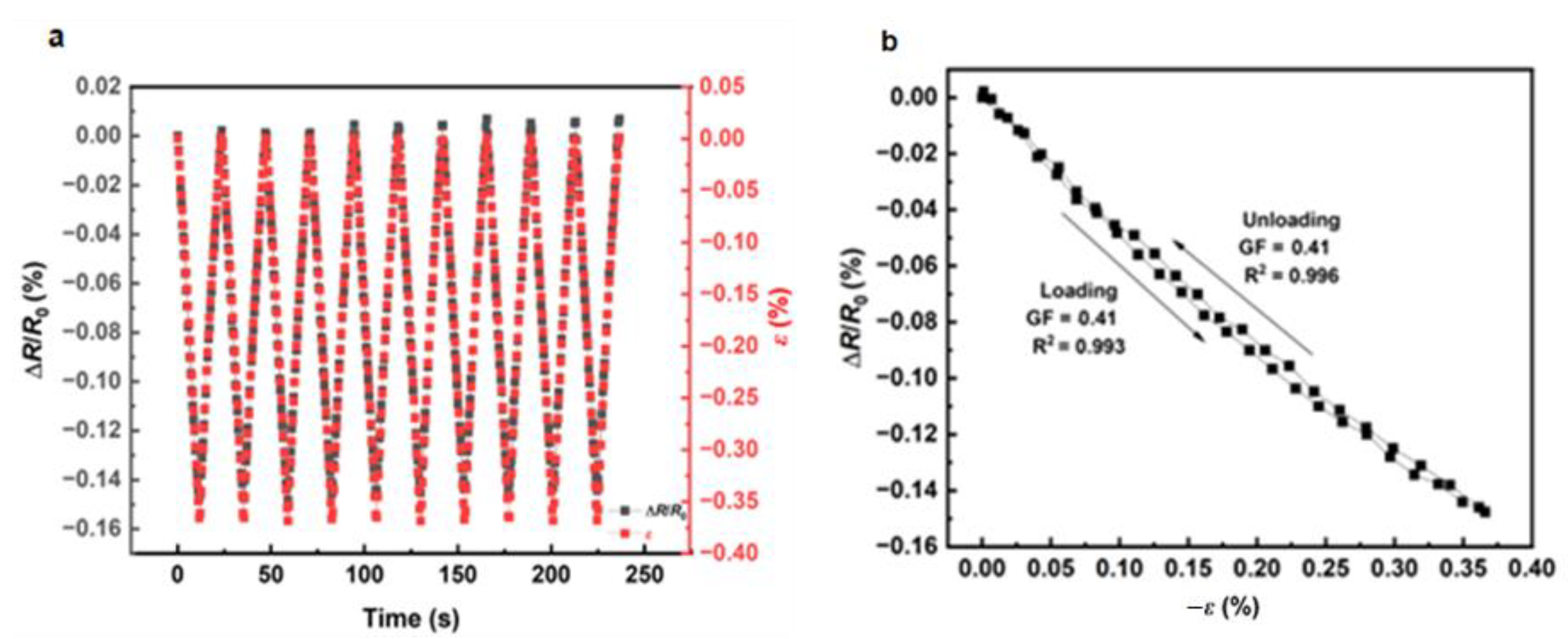
3.1. Piezoresistive Response of CNTY Monofilament Composites under Uniaxial Compression
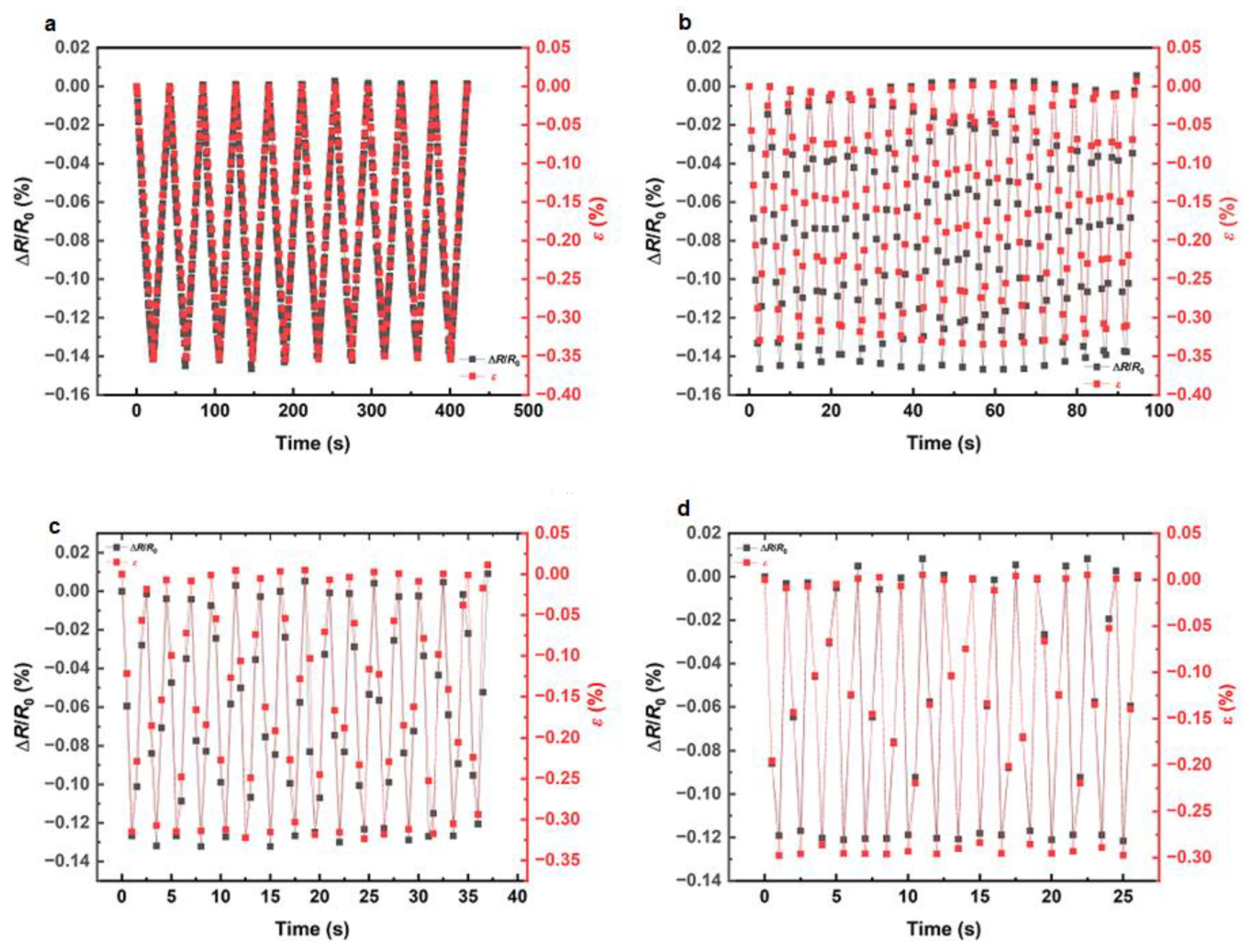
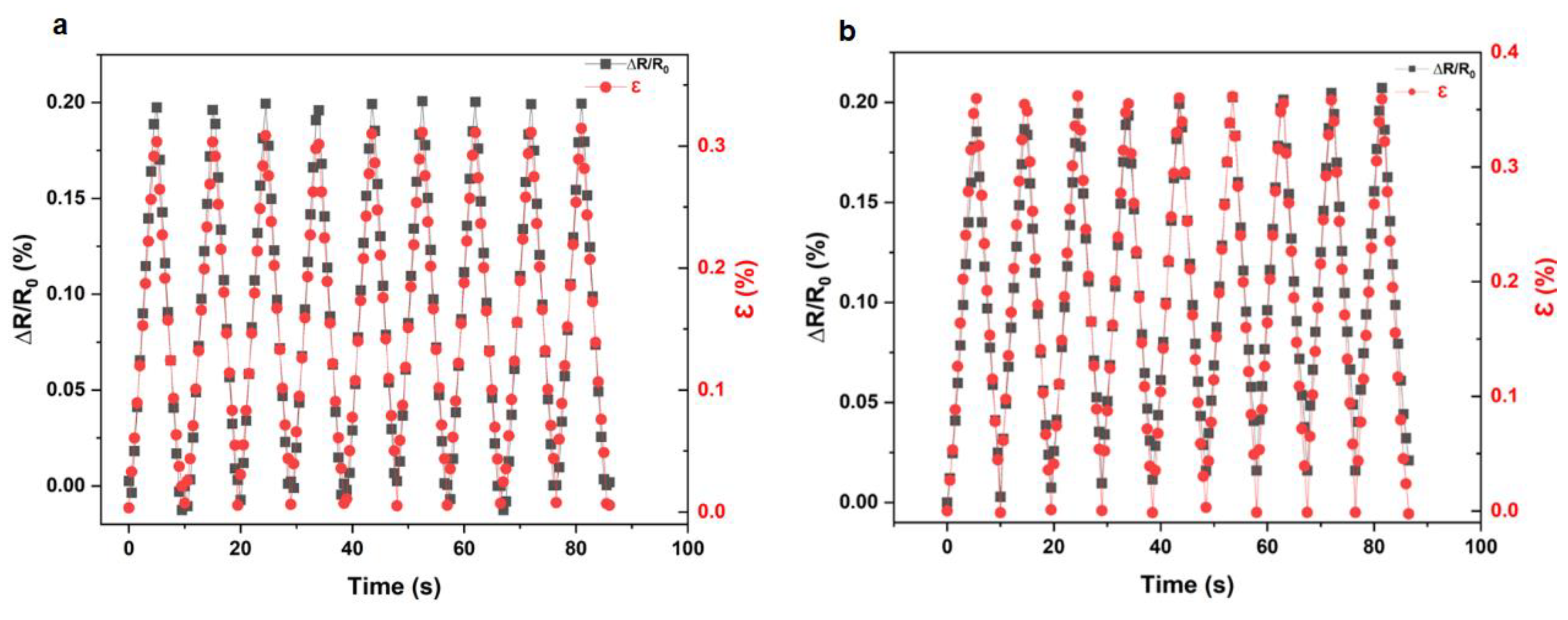
3.1.1. Strain Rate Effect
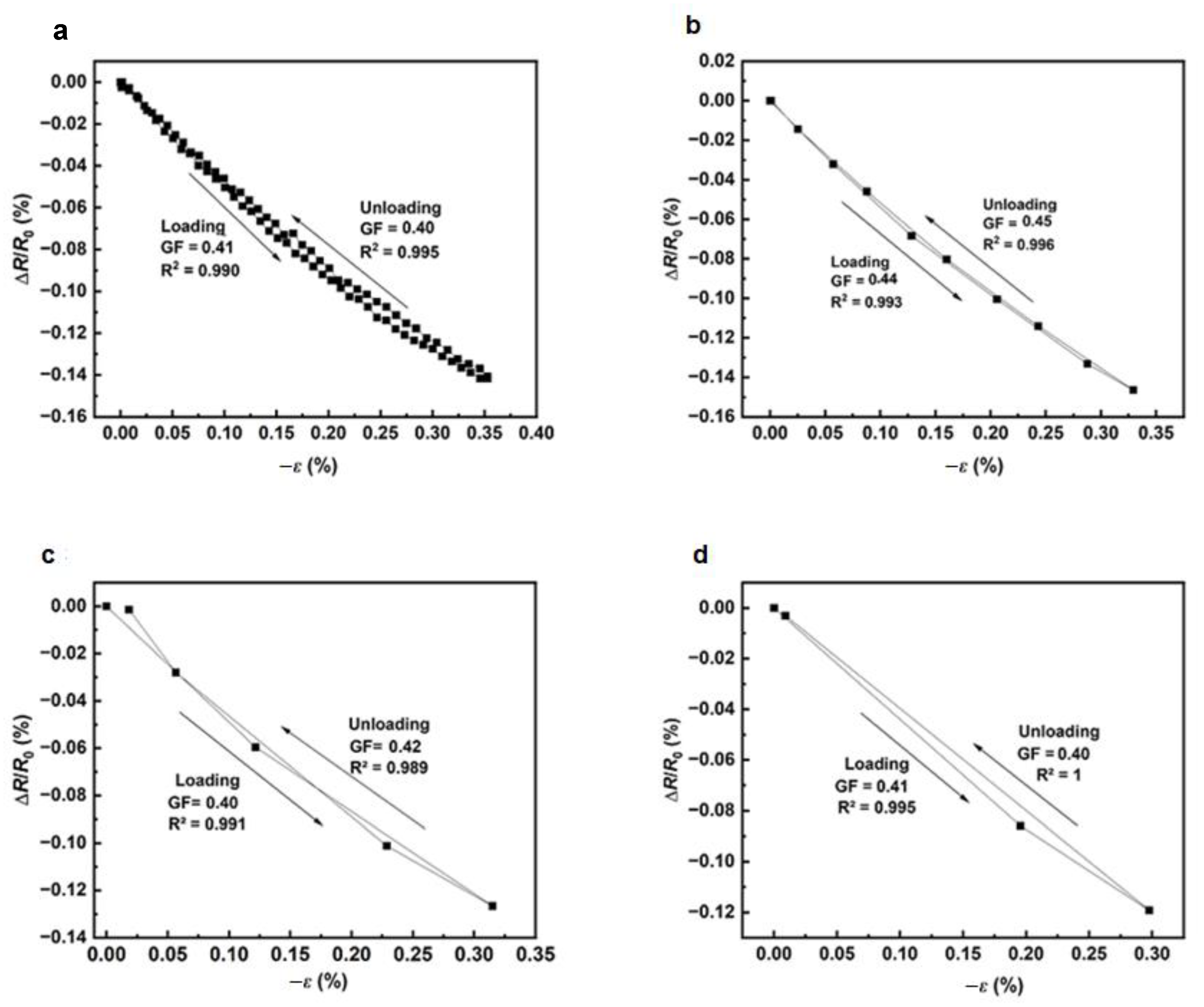
3.1.2. Hysteresis
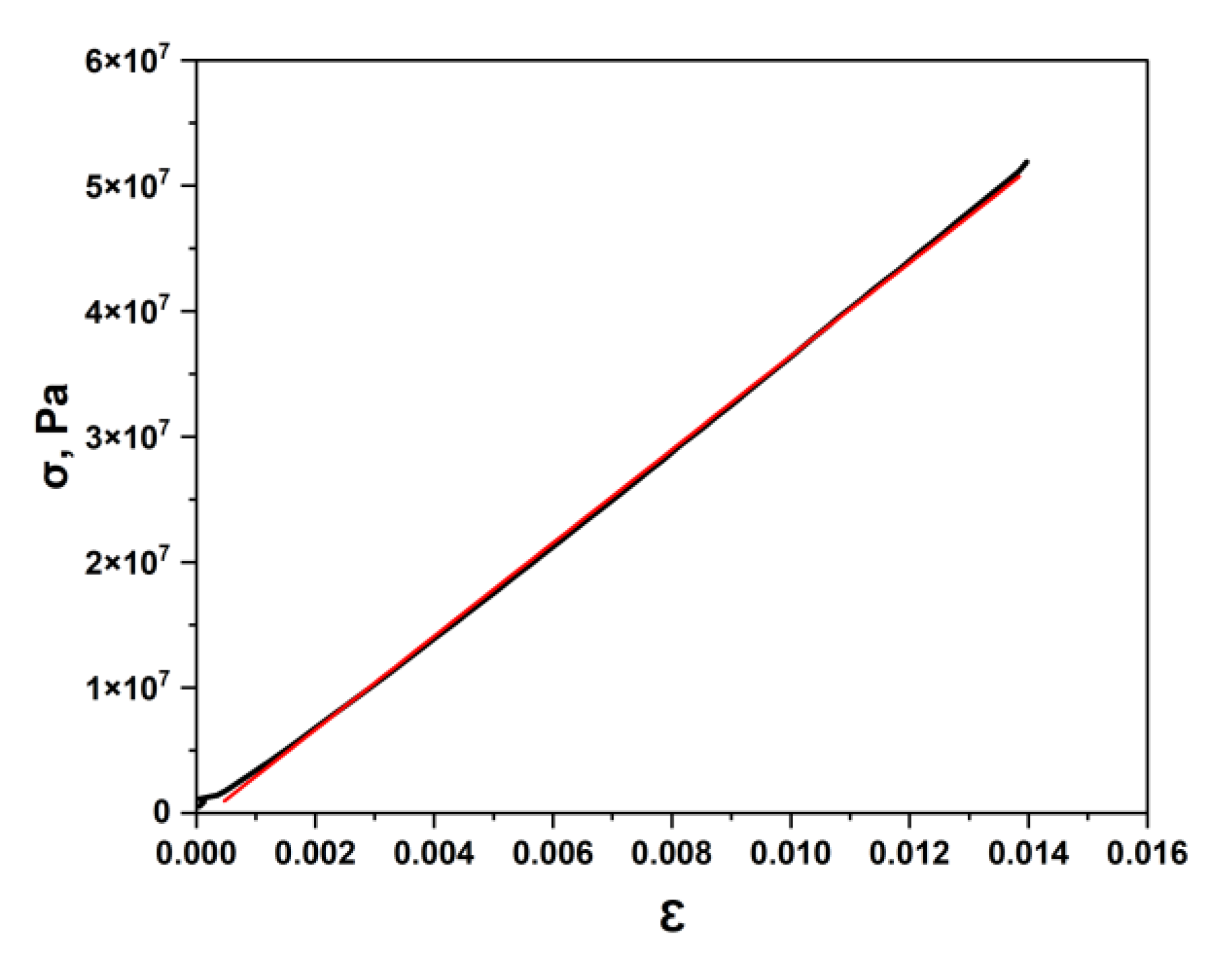
3.1.3. Stress-Strain Response
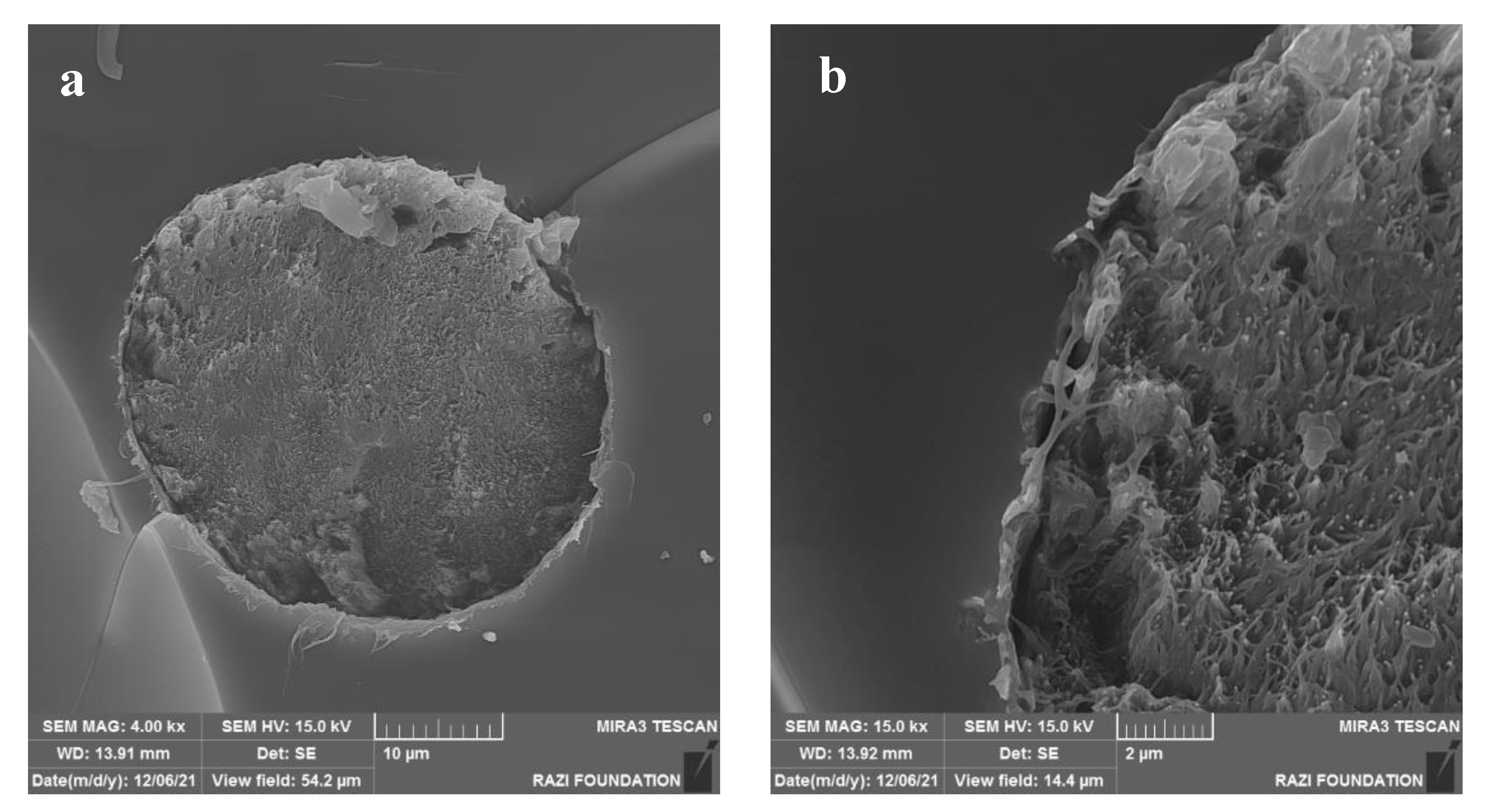
3.2. Scanning Electron Microscopy
3.3. Comparison of Piezoresistive Responses of Monofilament Composites under Uniaxial Compression and Tension
4. Conclusions
Author Contributions
Funding
Data Availability Statement
Acknowledgments
Conflicts of Interest
References
- Abot, J.L.; Rajan, C.P. Carbon nanotube fibers. In Carbon Nanomaterials Sourcebook: Graphene, Fullerenes, Nanotubes, and Nanodiamonds; Sattler, K.D., Ed.; Taylor and Francis: London, UK, 2016; Volume I, pp. 357–383. [Google Scholar]
- Thostenson, E.T.; Chou, T.-W. Real-time in situ sensing of damage evolution in advanced fiber composites using carbon nanotube networks. Nanotechnology 2008, 19, 215713. [Google Scholar] [CrossRef] [PubMed]
- Obitayo, W.; Liu, T. A review: Carbon nanotube-based piezoresistive strain sensors. J. Sens. 2012, 2012, 652438. [Google Scholar] [CrossRef]
- Wang, S.; Tang, L.A.; Bao, Q.; Lin, M.; Deng, S.; Goh, B.M.; Loh, K.P. Room temperature synthesis of soluble carbon nanotubes by the sonication of graphene oxide nanosheets. J. Am. Chem. Soc. 2009, 131, 16832–16837. [Google Scholar] [CrossRef] [PubMed]
- Gspann, T.S.; Montinaro, N.; Pantano, A.; Elliott, J.A.; Windle, A.H. Mechanical properties of carbon nanotube fibres: St Venant’s principle at the limit and the role of imperfections. C 2015, 93, 1021–1033. [Google Scholar] [CrossRef]
- Zhao, J.; Zhang, X.; Pan, Z.; Li, Q. Wide-range tunable dynamic property of carbon-nanotube-based fibers. Adv. Mater. Interfaces 2015, 2, 1500093. [Google Scholar] [CrossRef]
- Niu, M.; Cui, C.; Tian, R.; Zhao, Y.; Miao, L.; Hao, W.; Li, J.; Sui, C.; He, X.; Wang, C. Mechanical and thermal properties of carbon nanotubes in carbon nanotube fibers under tension–torsion loading. RSC Adv. 2022, 12, 30085–30093. [Google Scholar] [CrossRef]
- Li, Y.-L.; Kinloch, I.A.; Windle, A.H. Direct spinning of carbon nanotube fibers from chemical vapor deposition synthesis. Science 2004, 304, 276–278. [Google Scholar] [CrossRef]
- Alexopoulos, N.D.; Bartholome, C.; Poulin, P.; Marioli-Riga, Z. Structural health monitoring of glass fiber reinforced composites using embedded carbon nanotube (CNT) fibers. Compos. Sci. Technol. 2010, 70, 260–271. [Google Scholar] [CrossRef]
- Wang, X.; Bradford, P.D.; Liu, W.; Zhao, H.; Inoue, Y.; Maria, J.-P.; Li, Q.; Yuan, F.-G.; Zhu, Y. Mechanical and electrical property improvement in CNT/nylon composites through drawing and stretching. Compos. Sci. Technol. 2011, 71, 1677–1683. [Google Scholar] [CrossRef]
- Kahng, S.K.; Gates, T.S.; Jefferson, G.D. Strain and temperature sensing properties of multiwalled carbon nanotube yarn composites. In Proceedings of the SAMPE ’08 Fall Technical Conference, Memphis, TN, USA, 8–10 September 2008. [Google Scholar]
- Abot, J.L.; Schulz, M.J.; Song, Y.; Medikonda, S.; Rooy, N. Novel distributed strain sensing in polymeric materials. Smart Mater. Struct. 2010, 19, 085007. [Google Scholar] [CrossRef]
- Abot, J.L.; Song, Y.; Vatsavaya, M.S.; Medikonda, S.; Kier, Z.; Jayasinghe, C.; Rooy, N.; Shanov, V.N.; Schulz, M.J. Delamination detection with carbon nanotube thread in self-sensing composite materials. Compos. Sci. Technol. 2010, 70, 1113–1119. [Google Scholar] [CrossRef]
- Zhao, H.; Zhang, Y.; Bradford, P.D.; Zhou, Q.; Jia, Q.; Yuan, F.; Zhu, Y. Carbon nanotube yarn strain sensors. Nanotechnology 2010, 21, 305502. [Google Scholar] [CrossRef]
- Zhao, J.; Zhang, X.; Di, J.; Xu, G.; Yang, X.; Liu, X.; Yong, Z.; Chen, M.; Li, Q. Double-peak mechanical properties of carbon-nanotube fibers. Small 2010, 6, 2612–2617. [Google Scholar] [CrossRef] [PubMed]
- Zhao, Y.; Wei, J.; Vajtai, R.; Ajayan, P.M.; Barrera, E.V. Iodine doped carbon nanotube cables exceeding specific electrical conductivity of metals. Sci. Rep. 2011, 1, 83. [Google Scholar] [CrossRef] [PubMed]
- Abot, J.L.; Alosh, T.; Belay, K. Strain dependence of electrical resistance in carbon nanotubes. Carbon 2014, 70, 95–112. [Google Scholar] [CrossRef]
- Anike, J.; Bajar, A.; Abot, J.L. Time-dependent effects on the coupled mechanical-electrical response of carbon nanotube yarns under tensile loading. C 2016, 2, 3. [Google Scholar] [CrossRef]
- Anike, J.; Le, H.H.; Brodeur, G.; Kadavan, M.; Abot, J.L. Piezoresistive response of integrated CNT yarns under compression and tension: The effect of lateral constraint. C 2017, 3, 14. [Google Scholar] [CrossRef]
- Anike, J.C.; Belay, K.; Abot, J.L. Piezoresistive response of carbon nanotube yarns under tension: Parametric effects and phenomenology. New Carbon Mater. 2018, 33, 140–154. [Google Scholar] [CrossRef]
- Anike, J.C.; Belay, K.; Abot, J.L. Effect of twist on the electromechanical properties of carbon nanotube yarns. Carbon 2019, 142, 491–503. [Google Scholar] [CrossRef]
- Schadler, L.S.; Giannaris, S.C.; Ajayan, P.M. Load transfer in carbon nanotube epoxy composites. Appl. Phys. Lett. 1998, 73, 3842–3844. [Google Scholar] [CrossRef]
- Lekawa-Raus, A.; Koziol, K.K.K.; Windle, A.H. Piezoresistive effect in carbon nanotube fibers. ACS Nano 2014, 8, 11214. [Google Scholar] [CrossRef]
- Rodriguez-Uicab, O.; Tayyarian, T.; Abot, J.L. Effect of curing temperature of epoxy matrix on the electrical response of carbon nanotube yarn monofilament composites. J. Compos. Sci. 2022, 6, 43. [Google Scholar] [CrossRef]


| Strain Rate (min−1) | Strain Level −ε (%) | Relative Change in Electrical Resistance ∆R/R0 (%) | GF |
|---|---|---|---|
| 0.02 | 0.36 | −0.14 | 0.41 ± 0.01 |
| 0.04 | 0.36 | −0.15 | 0.41 ± 0.01 |
| 0.2 | 0.33 | −0.15 | 0.45 ± 0.01 |
| 0.4 | 0.32 | −0.13 | 0.41 ± 0.01 |
| 0.6 | 0.30 | −0.12 | 0.41 ± 0.01 |
| Strain Rate | Hysteresis HN (%) |
|---|---|
| 0.04 | −0.031 ± 0.010 |
| 0.02 | −0.024 ± 0.022 |
| 0.2 | −0.010 ± 0.017 |
| 0.4 | −0.0027 ± 0.015 |
| 0.6 | −0.035 ± 0.011 |
Disclaimer/Publisher’s Note: The statements, opinions and data contained in all publications are solely those of the individual author(s) and contributor(s) and not of MDPI and/or the editor(s). MDPI and/or the editor(s) disclaim responsibility for any injury to people or property resulting from any ideas, methods, instructions or products referred to in the content. |
© 2023 by the authors. Licensee MDPI, Basel, Switzerland. This article is an open access article distributed under the terms and conditions of the Creative Commons Attribution (CC BY) license (https://creativecommons.org/licenses/by/4.0/).
Share and Cite
Garcia Guerra, I.; Tayyarian, T.; Rodríguez-Uicab, O.; Abot, J.L. Piezoresistive Response of Carbon Nanotube Yarn Monofilament Composites under Axial Compression. C 2023, 9, 89. https://doi.org/10.3390/c9040089
Garcia Guerra I, Tayyarian T, Rodríguez-Uicab O, Abot JL. Piezoresistive Response of Carbon Nanotube Yarn Monofilament Composites under Axial Compression. C. 2023; 9(4):89. https://doi.org/10.3390/c9040089
Chicago/Turabian StyleGarcia Guerra, Iriana, Tannaz Tayyarian, Omar Rodríguez-Uicab, and Jandro L. Abot. 2023. "Piezoresistive Response of Carbon Nanotube Yarn Monofilament Composites under Axial Compression" C 9, no. 4: 89. https://doi.org/10.3390/c9040089
APA StyleGarcia Guerra, I., Tayyarian, T., Rodríguez-Uicab, O., & Abot, J. L. (2023). Piezoresistive Response of Carbon Nanotube Yarn Monofilament Composites under Axial Compression. C, 9(4), 89. https://doi.org/10.3390/c9040089